JP2005211737A - System for separating and recovering powder material - Google Patents
System for separating and recovering powder material Download PDFInfo
- Publication number
- JP2005211737A JP2005211737A JP2004019495A JP2004019495A JP2005211737A JP 2005211737 A JP2005211737 A JP 2005211737A JP 2004019495 A JP2004019495 A JP 2004019495A JP 2004019495 A JP2004019495 A JP 2004019495A JP 2005211737 A JP2005211737 A JP 2005211737A
- Authority
- JP
- Japan
- Prior art keywords
- powder
- air
- chamber
- separation
- port
- Prior art date
- Legal status (The legal status is an assumption and is not a legal conclusion. Google has not performed a legal analysis and makes no representation as to the accuracy of the status listed.)
- Pending
Links
Images


Abstract
Description
本発明は、射出成形において発生する不要な熱可塑性樹脂片等を回収し、粉砕して再利用する場合に、粉砕により得られた粒体材料に混入している粉体材料を分離するために用いるのに適した粉体材料の分離・回収システムに関するものである。また、本発明はかかるシステムに用いるのに適した粉取り装置に関するものである。 In the present invention, when unnecessary thermoplastic resin pieces and the like generated in injection molding are collected, pulverized and reused, the powder material mixed in the granular material obtained by pulverization is separated. The present invention relates to a powder material separation / recovery system suitable for use. The present invention also relates to a dust removing device suitable for use in such a system.
資源の有効活用を図るために、リサイクル(再利用)が広く行われるようになってきている。熱可塑性樹脂の射出成形の分野においても、射出成形により発生する成形品から切り取られた不要なスプール、ランナなどの部分や不良成形品等を回収し、これらを所定の大きさに粉砕して、バージン材料と共に射出成形用の材料として再利用に供されている。 In order to make effective use of resources, recycling (reuse) has been widely performed. Also in the field of thermoplastic resin injection molding, unnecessary spools, runners and other parts cut out from molded products generated by injection molding, defective molded products, etc. are collected, and these are crushed to a predetermined size, Along with virgin material, it is reused as a material for injection molding.
ここで、回収された熱可塑性樹脂片の粉砕時には、所定サイズの粒体材料の他に細かな粉体も発生するので、粉砕後には粒体材料に粉体材料が混入した状態となっている。このような混合材料をそのまま、射出成形材料として再利用すると、次のような不具合が生ずる。 Here, when the recovered thermoplastic resin piece is pulverized, fine powder is also generated in addition to the granular material of a predetermined size, so that the powder material is mixed into the granular material after pulverization. . When such a mixed material is reused as it is as an injection molding material, the following problems occur.
まず、粒体材料に混入している粉体材料は、材料を加熱溶融する成形機のスクリューおよび加熱筒内で粒体材料よりも早く溶融してスクリュー表面に滞留するので、長時間にわたり加熱を受け、スクリュー等の表面に焼き付いてしまう。焼き付いた粉体材料は、不定期的にスクリューなどの表面から剥離して成形材料の中に混入する。このような溶融材料を用いて射出成形を行うと、成形された製品には、焼けた粉体材料が原因となって黒点と呼ばれる成形不良が発生してしまう。このような黒点は、導光板、レンズ等の透明成形品、医療関係、食品関係に用いる成形品の製造においては確実に防止する必要がある。 First, the powder material mixed in the granular material melts faster than the granular material in the screw and heating cylinder of the molding machine that heats and melts the material and stays on the screw surface. It will burn onto the surface of the receiver and screw. The baked powder material is irregularly separated from the surface of a screw or the like and mixed into the molding material. When injection molding is performed using such a molten material, a molded defect called a black spot occurs in the molded product due to the burnt powder material. Such black spots need to be reliably prevented in the production of transparent molded products such as light guide plates and lenses, medical products, and food products.
また、材料を成形機に供給する前行程である材料乾燥行程においても、粒体材料に混入している粉体材料が、材料乾燥機の内面に付着し、時々、一挙に粉体の塊となって剥離して、粒体材料と一緒に成形機に供給されてしまう。粉体の塊の部分は、他の粒体材料の部分と比重が異なるので、成形機での加熱溶融工程を不安定にするとともに、材料が加熱溶融されたときの温度および密度を変動させる。このため、粉体の塊の部分が成形機に供給されると、成形された製品の寸法や重量等が規格から外れるという不具合が生ずる。 In addition, in the material drying process, which is the process before supplying the material to the molding machine, the powder material mixed in the granular material adheres to the inner surface of the material dryer, and sometimes the powder lump is formed at once. It peels off and is supplied to the molding machine together with the particulate material. The part of the lump of powder has a specific gravity different from that of the part of the other granular material, so that the heating and melting process in the molding machine becomes unstable and the temperature and density when the material is heated and melted are varied. For this reason, when the lump portion of the powder is supplied to the molding machine, there arises a problem that the size, weight, etc. of the molded product deviate from the standard.
このような不具合を解消するために、従来においては、粒体材料に混入している粉体材料を分離して除去するための装置が提案されている(特許文献1、2参照)。
特開平10−113929号公報に提案されている粉分離装置は、漏斗状の容器の側壁に多数の穴を開けてフィルタとし、このフィルタの外からブロワーによって装置内の空気を吸い出して粒体材料に混入している粉体材料を分離除去するように構成されている。しかしながら、フィルタの穴の近くを通る粒体材料の部分からは粉体材料を吸引除去できるが、フィルタから離れている部分に混入している粉体材料を吸引して除去することができないという問題がある。 Japanese Patent Laid-Open No. 10-119392 proposes a powder separation device in which a large number of holes are formed in a side wall of a funnel-shaped container to form a filter, and air inside the device is sucked out from the outside of the filter by a blower. The powder material mixed in is separated and removed. However, the powder material can be sucked and removed from the part of the granular material passing near the filter hole, but the powder material mixed in the part away from the filter cannot be sucked and removed. There is.
また、特開平9−29175号公報に提案されている粉分離装置は、装置内の空気を上方から金網のフィルタを介してブロワーによって吸引することにより、装置内の粒体材料を空気によって旋回させて、粒体材料に比べて軽い粉をフィルタを通して吸い取って分離排出するものである。しかしながら、分離排出の効率を上げるために空気の吸引力を高めると、フィルタの金網が、そこに集まる粉体材料によって目詰まりを起こしやすいという問題がある。 In addition, the powder separation device proposed in Japanese Patent Application Laid-Open No. 9-29175 has the air in the device swirled from above by a blower through a wire mesh filter, so that the granular material in the device is swirled by air. Thus, lighter powder than the granular material is sucked through the filter and separated and discharged. However, when the air suction force is increased in order to increase the efficiency of separation and discharge, there is a problem that the wire mesh of the filter is likely to be clogged by the powder material collected there.
一方、粉体分離装置からブロワーに至る経路上には、一般に、分離装置内から空気と共に吸い出した粉体材料を捕捉するためのエアーフィルタが配置されており、ブロワーの排気口から排気と共に粉体材料が外部に排出されてしまうことを防いでいる。ここで、粉体材料によってエアーフィルタが目詰まりを起こすと、ブロワーによる粉体分離装置からの粉体吸引能力が低下する。このため、従来では、粉体分離除去動作の後にフィルタクリーニング動作が行われ、このフィルタクリーニング動作では、ブロワーモータを逆方向に回転させて、エアーフィルタを介して逆方向に空気を流して、エアーフィルタの目に詰まった粉体材料を強制的に排除する、所謂、逆洗を行っている。しかしながら、この逆洗を行うためには、正方向に回転しているブロワーモータを止めて逆回転させる必要がある。正転状態のブロワーモータを直ちに逆転すると、過負荷状態に陥ってしまうので、正転状態のモータが停止するのを待って逆転駆動する必要がる。したがって、モータが停止するための待ち時間の分、運転サイクルが長くなり、作業効率が悪いという問題がある。 On the other hand, on the path from the powder separator to the blower, an air filter for capturing the powder material sucked together with air from the inside of the separator is generally arranged. The material is prevented from being discharged to the outside. Here, when the air filter is clogged with the powder material, the ability to suck the powder from the powder separation device by the blower is lowered. For this reason, conventionally, a filter cleaning operation is performed after the powder separation and removal operation. In this filter cleaning operation, the blower motor is rotated in the reverse direction, and air is allowed to flow in the reverse direction through the air filter. So-called backwashing is performed in which the powder material clogged in the filter is forcibly removed. However, in order to perform this backwashing, it is necessary to stop and rotate the blower motor rotating in the forward direction. If the forward rotation blower motor is reversely rotated immediately, it will fall into an overload state, so it is necessary to drive the reverse rotation after the normal rotation state motor stops. Therefore, there is a problem that the operation cycle becomes long and the work efficiency is poor due to the waiting time for the motor to stop.
ここで、特願2002−234525号において、粒体材料に混入している粉体材料を効率良く分離するための粉体材料を分離する方法および装置が提案されている。 Here, Japanese Patent Application No. 2002-234525 proposes a method and an apparatus for separating a powder material for efficiently separating the powder material mixed in the granular material.
本発明の課題は、上記の装置を改良して、混合材料の供給動作、粉体材料の分離動作、粉体材料が分離された後の粒体材料の排出動作、および分離された粉体材料の回収動作を同時並行して行うことのできる粉体材料の分離・回収システムを提案することにある。 An object of the present invention is to improve the above-described apparatus to supply a mixed material, to separate a powder material, to discharge a granular material after the powder material is separated, and to separate the powder material. It is to propose a powder material separation / recovery system capable of performing the recovery operations simultaneously.
また、本発明の課題は、粉体材料を回収するために用いるフィルタのクリーニング動作を効率良く行うことのできる粉体材料の分離・回収システムを提案することにある。 Another object of the present invention is to propose a powder material separation / recovery system capable of efficiently performing a cleaning operation of a filter used for recovering a powder material.
さらに、本発明の課題は、粉体材料の分離・回収システムに用いるのに適した粉取り装置を提案することにある。 Another object of the present invention is to propose a powder removing device suitable for use in a powder material separation / recovery system.
上記の課題を解決するために、本発明の粉体材料および粒体材料を含む混合材料から粉体材料を分離除去するための粉取り装置は、
粉排出室と、
前記粉分離室および前記粉排出室を仕切っている仕切り壁と、
前記仕切り壁に取り付けられた粉体材料が通過可能なフィルタと、
前記仕切り壁の側から下方に傾斜している前記粉分離室に配置した傾斜板と、
前記粉分離室の外部から前記傾斜板の表面に、粉体材料および粒体材料を含む混合材料を自重によって落下させる材料供給筒と、
前記傾斜板の上部に配置した材料ガイド板と、
前記傾斜板の下端部分に形成した吹き上げエアー形成用の隙間と、
前記隙間を介して前記粉分離室に空気を吹き込むためのエアー吹き込み口と、
前記粉分離室から粒体材料を排出するために、前記傾斜底面の側方に形成した粒体材料の落下穴と、
前記粉排出室から粉体材料を排出するための粉排出口とを有していることを特徴としている。
In order to solve the above problems, a powder removing device for separating and removing a powder material from a mixed material including the powder material and the granule material of the present invention,
A powder discharge chamber;
A partition wall partitioning the powder separation chamber and the powder discharge chamber;
A filter through which the powder material attached to the partition wall can pass;
An inclined plate disposed in the powder separation chamber inclined downward from the partition wall side;
A material supply cylinder for dropping a mixed material containing a powder material and a granular material by its own weight from the outside of the powder separation chamber onto the surface of the inclined plate;
A material guide plate disposed on top of the inclined plate;
A gap for forming blown air formed in the lower end portion of the inclined plate,
An air blowing port for blowing air into the powder separation chamber through the gap;
In order to discharge the particulate material from the powder separation chamber, a dropping hole for the particulate material formed on the side of the inclined bottom surface,
It has the powder discharge port for discharging | emitting powder material from the said powder discharge chamber, It is characterized by the above-mentioned.
また、本発明の粉体材料の分離・回収システムは、
上記構成の粉取り装置と、前記粉取り装置において除去された粉体材料を回収する粉回収装置と、空気吹き込み・吸引装置とを有しており、
前記粉回収装置は、
通過する空気流から粉体材料を捕捉可能な粉回収用フィルタと、
前記粉回収用フィルタによって仕切られている第1室および第2室と、
前記第1室に粉体材料を回収するために、前記粉取り装置の前記粉排出口に連通している粉回収口と、
前記第2室から空気を吸引するエアー吸引口とを備えていることを特徴としている。
In addition, the powder material separation and recovery system of the present invention,
It has a powder removing device having the above configuration, a powder collecting device for collecting the powder material removed in the powder removing device, and an air blowing / suction device,
The powder recovery device
A powder recovery filter capable of capturing the powder material from the passing air stream;
A first chamber and a second chamber partitioned by the powder recovery filter;
A powder collection port communicating with the powder discharge port of the powder removing device to collect the powder material in the first chamber;
An air suction port for sucking air from the second chamber is provided.
また、前記エアー吹き込み・吸引装置は、
前記粉取り装置の前記エアー吹き込み口に連通しているエアー吐出口と、
前記粉回収装置の前記エアー吸引口に連通しているエアー吸引口とを備えたことを特徴としている。
The air blowing / suction device is
An air discharge port communicating with the air blowing port of the dust removing device;
And an air suction port communicating with the air suction port of the powder recovery device.
この構成の粉体材料の分離・回収システムにおいて、エアー吹込み・吸引装置を駆動すると、粉取り装置のエアー吹込み口から空気が吹き込まれて、分離室の傾斜板の下端部の隙間から分離室内に空気が吹き上げられる。材料供給筒からは混合材料が自重によって投入され、投入された混合材料が傾斜板に沿って滑落し、隙間から吹き上げられているエアーに乗って上方に吹き上げられる。吹き上げられた混合材料は、材料ガイド板によって案内されて、反対側に位置している仕切り壁のフィルタに衝突して再び傾斜板の上端側に落下する。混合材料が吹き上げ空気流によって上下に循環してフィルタに衝突する毎に、混合材料に含まれている粉体材料のみがフィルタを通って排出室の側に排出される。粉体材料が分離除去された後の粒体材料は、傾斜板の側方に位置している落下穴から自重により落下する。例えば、落下穴の下側部分を射出成形装置の材料供給口に接続しておけば、粉体材料が分離除去された後の粒体材料を当該射出成形装置に供給できる。 In the powder material separation / recovery system with this configuration, when the air blowing / suction device is driven, air is blown from the air blowing port of the dust removing device and separated from the gap at the lower end of the inclined plate of the separation chamber. Air is blown up into the room. The mixed material is charged from the material supply cylinder by its own weight, and the charged mixed material slides down along the inclined plate, and is blown upward on the air blown from the gap. The mixed material blown up is guided by the material guide plate, collides with the filter of the partition wall located on the opposite side, and falls again to the upper end side of the inclined plate. Each time the mixed material circulates up and down by the blown air flow and collides with the filter, only the powder material contained in the mixed material is discharged to the discharge chamber side through the filter. The granular material after the powder material is separated and removed falls by its own weight from a dropping hole located on the side of the inclined plate. For example, if the lower part of the drop hole is connected to the material supply port of the injection molding apparatus, the granular material after the powder material is separated and removed can be supplied to the injection molding apparatus.
一方、粉取り装置の排出室は、粉回収装置を介して、エアー吹込み・吸引装置によって吸引されているので、排出室に排出された粉体材料は空気流に乗って粉排出口から粉回収装置の側に吸引されて、粉回収口から第1室内に回収される。第1室に吸引された空気流は粉体回収用フィルタを介して第2室の側に吸引され、空気流に含まれている粉体材料が当該フィルタによって分離除去されるので、空気のみが第2室を介して、エアー吹込み・吸引装置のエアー吸引口の側に還流する。このようにして、粉取り装置で分離除去された粉体材料が粉回収装置の第1室に回収される。 On the other hand, since the discharge chamber of the powder removal device is sucked by the air blowing / suction device through the powder recovery device, the powder material discharged into the discharge chamber rides on the air flow and is discharged from the powder discharge port. It is sucked into the collecting device and collected in the first chamber from the powder collecting port. The air flow sucked into the first chamber is sucked into the second chamber through the powder recovery filter, and the powder material contained in the air flow is separated and removed by the filter. It returns to the side of the air suction port of the air blowing / suction device through the second chamber. In this manner, the powder material separated and removed by the powder removing device is collected in the first chamber of the powder collecting device.
したがって、本発明の粉取り装置では、混合材料の供給動作、粉体材料の分離除去動作、粉体材料が分離除去された後の粒体材料の排出動作を同時並行して行うことができる。同様に、本発明の粉体材料の分離・回収システムでは、混合材料の供給動作、粉体材料の分離除去動作、粉体材料が分離除去された後の粒体材料の排出動作、および分離された粉体材料の回収動作を同時並行して行うことができる。 Therefore, in the powder removing apparatus of the present invention, the mixed material supply operation, the powder material separation / removal operation, and the granule material discharge operation after the powder material is separated and removed can be performed simultaneously. Similarly, in the powder material separation / recovery system of the present invention, the mixed material supply operation, the powder material separation / removal operation, the granular material discharge operation after the powder material is separated and removed, and the separation are performed. The powder material can be collected in parallel.
ここで、本発明のシステムは、前記粉取り装置、前記粉回収装置および前記エアー吹き込み・吸引装置を駆動制御する制御装置を有した構成とすることができる。この場合には、前記粉取り装置に、落下穴から落下した粒体材料が通過する材料供給管と、前記材料供給管を通過する粒体材料の有無を検出する材料センサを配置し、前記材料センサにより粒体材料が無いことが検出されると、前記制御装置によって、所定時間の間、前記エアー吹き込み・吸引装置を駆動して、前記粉取り装置による粉分離動作および前記粉回収装置による粉回収動作を行わせるようにすればよい。 Here, the system of the present invention can be configured to have a control device that drives and controls the dust removing device, the powder collecting device, and the air blowing / suction device. In this case, a material supply pipe through which the granular material dropped from the drop hole passes and a material sensor for detecting the presence or absence of the granular material passing through the material supply pipe are arranged in the powder removing device, and the material When the sensor detects that there is no granular material, the control device drives the air blowing / suction device for a predetermined time to separate the powder by the powder removing device and the powder by the powder collecting device. A collection operation may be performed.
また、前記粉回収装置は、前記エアー吹き込み・吸引装置の前記エアー吐出口を、前記第2室および前記粉取り装置の前記エアー吹き込み口に選択的に連通させるためのエアー吹込み切換弁と、前記エアー吹込み・吸引装置の前記エアー吸引口を、前記第2室および大気開放側に選択的に連通させるためのエアー吸引切換弁と、前記第1室を大気開放するための大気開放弁とを備えた構成とすることができる。 In addition, the powder recovery device, the air blowing switching valve for selectively communicating the air discharge port of the air blowing and suction device to the second chamber and the air blowing port of the powder removing device, An air suction switching valve for selectively communicating the air suction port of the air blowing / suction device to the second chamber and the atmosphere opening side; and an atmosphere opening valve for opening the first chamber to the atmosphere; It can be set as the structure provided with.
この場合には、前記制御装置は、前記エアー吹込み切換弁を切り換えて、前記エアー吹込み・吸引装置の前記エアー吐出口を前記第2室に連通させ、前記エアー吸引切換弁を切り換えて、前記エアー吹込み・吸引装置の前記エアー吸引口を大気開放し、前記大気開放弁を介して前記第1室を大気開放し、この状態で前記エアー吹込み・吸引装置を駆動して、前記粉回収用フィルタを介して前記第2室から前記第1室に空気を流すことにより、当該粉回収用フィルタのクリーニングを行うことができる。 In this case, the control device switches the air blowing switching valve, connects the air discharge port of the air blowing / suction device to the second chamber, switches the air suction switching valve, The air suction port of the air blowing / suction device is opened to the atmosphere, the first chamber is opened to the atmosphere via the atmosphere release valve, and the air blowing / suction device is driven in this state to The powder recovery filter can be cleaned by flowing air from the second chamber to the first chamber through the recovery filter.
このようにすれば、エアー吹込み・吸引装置を構成しているブロワーなどの駆動モータの回転方向を切り換えて、フィルタを通って流れる空気流の方向を切り換える必要がないので、フィルタのクリーニング動作に直ちに入ることができる。よって、効率良くフィルタのクリーニング動作を行うことができる。 In this way, it is not necessary to switch the rotation direction of a drive motor such as a blower constituting the air blowing / suction device, and to switch the direction of the air flow flowing through the filter. You can enter immediately. Therefore, the filter cleaning operation can be performed efficiently.
ここで、前記制御装置によって、前記粉分離動作および前記粉回収動作を所定時間行った後に、前記粉回収用フィルタのクリーニング動作を所定時間行うようにすればよい。 Here, after the powder separation operation and the powder recovery operation are performed for a predetermined time by the control device, the cleaning operation of the powder recovery filter may be performed for a predetermined time.
次に、前記粉回収装置に、前記第1室の底部に形成した粉体材料排出口と、前記粉体材料排出口を開閉する開閉弁とを配置し、第1室に溜まった粉体材料を粉回収袋などに回収すればよい。この場合、前記制御装置によって、前記クリーニング動作の終了後に所定時間だけ前記開閉弁を駆動して前記粉体材料排出口を開放すれば、手動によらず、粉体材料を第2室から排出できる。 Next, a powder material discharge port formed at the bottom of the first chamber and an on-off valve for opening and closing the powder material discharge port are arranged in the powder recovery device, and the powder material collected in the first chamber May be collected in a powder collection bag or the like. In this case, the powder material can be discharged from the second chamber without manual operation if the control device drives the on-off valve for a predetermined time after the cleaning operation is completed to open the powder material discharge port. .
本発明の粉体材料の分離・回収システムは、射出成形により発生した不要な熱可塑性樹脂片を回収して粉砕することにより得られた混合材料から、粉体材料を分離するのに適している。粉取り装置を射出成形装置の材料供給口に取り付けると、粉体材料が確実に分離除去された後の粒体材料のみを射出成形装置に供給できるので、焼けた粉体材料が原因による黒点と呼ばれる成形不良や、粉体材料が塊となって射出成形装置に供給されることが原因による成形品の寸法や重量等が規格から外れてしまうという成形不良の発生を抑えることができ、寸法精度の高い成形品を歩留まり良く製造できる。 The powder material separation / recovery system of the present invention is suitable for separating powder material from a mixed material obtained by collecting and crushing unnecessary thermoplastic resin pieces generated by injection molding. . If the powder removal device is attached to the material supply port of the injection molding device, only the granular material after the powder material has been reliably separated and removed can be supplied to the injection molding device. It is possible to suppress the occurrence of molding defects called molding defects and molding defects due to the fact that the size and weight of molded products are out of the standard due to the fact that powder material is supplied to the injection molding machine as a lump. Can be manufactured with high yield.
本発明の粉取り装置では、混合材料の供給動作、粉体材料の分離除去動作、粉体材料が分離除去された後の粒体材料の排出動作を同時並行して行うことができる。同様に、本発明の粉体材料の分離・回収システムでは、混合材料の供給動作、粉体材料の分離除去動作、粉体材料が分離除去された後の粒体材料の排出動作、および分離された粉体材料の回収動作を同時並行して行うことができる。よって、効率良く混合材料から粉体材料を分離回収することができる。 In the powder removing apparatus of the present invention, the mixed material supply operation, the powder material separation / removal operation, and the particle material discharge operation after the powder material is separated and removed can be performed in parallel. Similarly, in the powder material separation / recovery system of the present invention, the mixed material supply operation, the powder material separation / removal operation, the granular material discharge operation after the powder material is separated and removed, and the separation are performed. The powder material can be collected in parallel. Therefore, it is possible to efficiently separate and recover the powder material from the mixed material.
また、本発明の粉取り装置では、上下に循環する空気流によって、混合材料を繰り返しフィルタに衝突させて、混合材料に含まれている粉体材料を分離除去し、分離室内に粒体材料のみを残すようになっている。フィルタには混合材料が繰り返し当たるので、フィルタの目に詰まった粒体が混合材料の衝突によって振り落とされる。よって、フィルタの目詰まりを防止でき、混合材料の全体から、むらなく、連続的に粉体材料を効率良く分離除去できる。 In the powder removing apparatus of the present invention, the mixed material is repeatedly collided with the filter by the air flow circulating up and down to separate and remove the powder material contained in the mixed material, and only the granular material is contained in the separation chamber. To leave. Since the mixed material repeatedly hits the filter, particles clogged in the filter are shaken off by the collision of the mixed material. Therefore, clogging of the filter can be prevented, and the powder material can be separated and removed efficiently and continuously from the entire mixed material.
さらに、本発明の粉回収装置では、エアー吹込み・吸引装置との間の空気流通経路を切換弁によって切り換えることにより、粉体材料を捕捉するためのフィルタを流れる空気流の方向を変えて、当該フィルタのクリーニングを行っている。それ故、粉体回収動作からフィルタクリーニング動作(逆洗動作)への切り換えを直ちに行うことができるので、従来のようなブロワーモータを逆転させる場合に比べて、運転サイクルを短縮化できる。 Furthermore, in the powder recovery device of the present invention, the air flow path between the air blowing / suction device is switched by the switching valve, thereby changing the direction of the air flow flowing through the filter for capturing the powder material, The filter is being cleaned. Therefore, since the switching from the powder recovery operation to the filter cleaning operation (back washing operation) can be performed immediately, the operation cycle can be shortened as compared with the case where the blower motor is reversely rotated.
以下に、図面を参照して、本発明を適用した粉体材料の分離・回収システムの一例を説明する。 An example of a powder material separation / recovery system to which the present invention is applied will be described below with reference to the drawings.
(全体構成)
図1は、粉体材料の分離・回収システムを射出成形装置の材料供給システムに取り付けた場合の例を示す説明図である。本例の粉体材料の分離・回収システム1は、射出成形後に回収されて粉砕されることにより得られた粒体材料および粉体材料が含まれている熱可塑性樹脂の混合材料から粉体材料を分離するためのシステムであり、粉体材料および粒体材料が含まれている混合材料から粉体材料を分離する粉取り装置2と、分離した粉体材料を粉取り装置2から回収する粉回収装置4と、粉取り装置2および粉回収装置4に粉体材料の分離用および回収用の空気流を形成するためのブロワーなどのエアー吹込み・吸引装置8と、動作制御を行うための制御装置10とを有している。粉取り装置2は、射出成形装置100の材料供給口101と、材料供給ホッパ102との間に取り付けられる。
(overall structure)
FIG. 1 is an explanatory view showing an example in which a powder material separation / collection system is attached to a material supply system of an injection molding apparatus. The separation /
(粉取り装置)
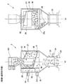
図2は粉取り装置2の内部構造を示す概略断面図であり、図2(a)は図2(b)のA−A線で切断した部分の概略断面図であり、図2(b)は図2(a)のB−B線で切断した部分の概略断面図である。粉取り装置2は粉取り箱21を備え、この粉取り箱21は矩形筒部分21aと、この下端から下方に延びている先細りの筒状部21bとを備え、矩形筒状部21aの上端が天板21cによって封鎖されている。天板21cの中心にはホッパ接続穴21dが形成されており、この接続穴21dに同軸状に材料供給ホッパ102が取り付けられている。粉取り箱21の下端開口には、同軸状態で透明ガラス管22が取り付けられており、この透明ガラス管22の下端に取り付けたフランジ23が射出成形装置100の材料供給口101に固定されている。透明ガラス管22の外側にはここを落下する粒体材料の有無を検出するための材料センサ24が配置されている。
(Powder removal device)
FIG. 2 is a schematic cross-sectional view showing the internal structure of the
粉取り箱21の内部は、矩形筒部分21aと筒状部21bの間に配置した水平仕切り壁25によって上下に仕切られている。上側の内部空間は、垂直仕切り壁26によって前後に仕切られており、前側の広い区画室が粉分離室27とされ、後側の狭い区画室が粉排出室28とされている。垂直仕切り壁26の上半部分には矩形のフィルタ29が取り付けられている。フィルタ29は上下に延びる一定幅のスリットが一定間隔で形成されたものである。スリットの幅は、混合材料に含まれている粉体材料は通過可能であるが、粒体材料は通過できないサイズとされている。
The inside of the
粉分離室27の内部には、垂直仕切り壁26の側から前方に向けて下側に傾斜している傾斜板30が配置されている。傾斜板30は粉分離室27の一方の側面27aから他方の側面27bの近傍位置まで延びている。傾斜板30と側面27bの隙間に対峙している水平仕切り壁25の部位には材料落下穴25aが形成されている。また、傾斜板30の前端縁と粉分離室27の前面27cの間には吹き上げ空気形成用の隙間31が形成されている。傾斜板30の前側部分の真上には、前面27cから後方に向けて上側に傾斜した状態で矩形の材料ガイド板32が取り付けられている。ここで、粉分離室27の天面27dから側面27aに沿って、ほぼL状の材料供給筒33が配置されており、この材料供給筒33の上端開口がホッパ接続穴21dに連通している。材料供給筒33の下端開口33aは、傾斜板30の前後方向の中程の部分の真上近傍に位置している。材料ガイド板32の後端は、材料供給筒33の側面まで延びている。
An
粉取り箱21の背面には、上側に粉排出口34が取り付けられており、この粉排出口34は粉排出室28に連通している。粉排出口34の下側にはエアー吹込み口35が取り付けられており、このエアー吹込み口35は、垂直仕切り壁26の下端部分に形成した連通穴26aを通って、粉分離室27における傾斜板30の下側空間36に連通している。
A
なお、粉取り箱21の上面に取り付けられている材料供給ホッパ102には、不図示の材料供給源から混合材料が供給される材料供給口103が形成されており、この材料供給口103の上側にはエアー吸引口104が形成されている。材料供給口103から混合材料を材料供給ホッパ102内に供給した後の空気は、フィルタ105を介してエアー吸引口104から吸引されるようになっている。
The
(粉回収装置)
図3は粉回収装置4を示す概略断面図である。粉回収装置4は、下端部分が円錐台状に窄まった円筒状の粉回収箱41を備えており、粉回収箱41の下端には粉排出口42が形成されており、この粉排出口42は開閉弁43によって開閉可能となっている。粉回収箱41の内部には、同心状態で円筒状の粉体捕捉用のエアーフィルタ44が配置されている。このエアーフィルタ44の下端開口は円盤45で封鎖されている。エアーフィルタ44の上端面には環状板46が取り付けられており、この環状板46の外周縁は粉回収箱41の内周面部分に密着している。したがって、粉回収箱41の内部空間は、エアーフィルタ44と、円盤45および環状板46とによって上下に仕切られ、下側が粉体材料を回収するための第1室47とされ、上側が第2室48とされている。
(Powder recovery device)
FIG. 3 is a schematic sectional view showing the
下側の第1室47には粉回収口49が形成されており、この粉回収口49は、回収管51を介して、粉取り装置2の粉排出口34に連通している。また、第1室47には大気連通口52が形成されており、この大気連通口52は、フィルタ53が内蔵されているフィルタ箱54を介して大気開放口55に連通可能となっている。通常は、大気開放口55とフィルタ箱54の間の連通口56が大気開放弁57によって閉鎖されている。
A
上側の第2室48には2箇所に連通口58、59が形成されている。一方の連通口58は、エアー吹込み切換弁61を切り換えると、エアー吹込み口62に連通可能である。エアー吹込み口62はエアー供給管83を介してエアー吹込み・吸引装置8のエアー吐出口81に連通しており、エアー吹出し口63は連通管64を介して粉取り装置2のエアー吹込み口35に連通している。したがって、エアー吹込み切換弁61によって連通口58が閉鎖された状態では、エアー吹込み口62がエアー吹出口63に連通して、空気が粉回収装置4をバイパスして、粉取り装置2の側に供給される。エアー吹込み切換弁61を開くと、エアー吹込み口62とエアー吹出し口63の間が遮断され、代わって、エアー吹込み口62が連通口58に連通する。よって、エアー吹込み・吸引装置8からの空気がエアー吹込み口62から連通口58を通って第2室48の内部に供給される。
In the upper
他方の連通口59は、エアー吸引切換弁65を切り換えると、エアー吸引口66に連通可能である。エアー吸引口66は、エアー吸引管84を介してエアー吹込み・吸引装置8のエアー吸引口82に連通している。通常は、エアー吸引切換弁65が開いており、連通口59がエアー吸引口66に連通している。エアー吸引切換弁65を閉じると、連通口59が閉鎖され、エアー吸引口66がフィルタ付きの大気開放口67に連通する。
The
(動作の説明)
制御装置10は、粉取り装置2の材料センサ24の出力に基づき、エアー吹き込み・吸引装置8を駆動制御し、また、所定のシーケンスに従って、エアー吹込み切換弁61、エアー吸引切換弁65、大気開放弁57および開閉弁43を駆動制御する。これにより、粉取り装置2による混合材料からの粉体材料の分離動作、粉回収装置4による分離された粉体材料の回収動作、粉回収装置4のエアーフィルタ44のクリーニング動作、および粉回収装置4に回収された粉体材料の排出動作が行われる。
(Description of operation)
The
まず、図4および図5を参照して、混合材料からの粉体材料の分離動作および、分離された粉体材料の回収動作を説明する。制御装置10は、粉取り装置2の材料センサ24によって透明ガラス管22を通って射出成形装置100に供給される粒体材料が無くなったことを検出すると、エアー吹込み・吸引装置8を駆動する。粉回収装置4では、連通口58がエアー吹込み切換弁61によって封鎖され、連通口59が開放状態とされ、粉排出口42は閉じ状態とされる。したがって、エアー吹込み・吸引装置8のエアー吐出口81からの空気は、粉取り装置2のエアー吹込み口35から分離室27内に供給され、ここからフィルタ29を通って粉排出室28の粉排出口34から排出され、粉回収装置4の粉回収口49から第1室47に供給され、エアーフィルタ44を通って第2室48から連通口59を通ってエアー吸引口66からエアー吹出し・吸引装置8のエアー吸引口82に戻るエアー循環路が形成される。
First, the separation operation of the powder material from the mixed material and the recovery operation of the separated powder material will be described with reference to FIG. 4 and FIG. When the
図5に示すように、粉取り装置2の分離室27においては、傾斜板30の前端の隙間31から空気が分離室27内に吹き上げられる。傾斜板30には、材料供給筒33によって混合材料が自重によって落下し、傾斜板30に沿って滑落する。傾斜板30の前端まで滑落した混合材料は吹き上げ空気によって上方に吹き上げられる。吹き上げられた混合材料は、材料ガイド板32によって後方に案内されて、分離室27の後面に配置されているフィルタ29に当り、当該フィルタ29に沿って再び傾斜板30に落下する。このような上下方向の循環が繰り返される間に、フィルタ29を通って粉体材料が分離されて背面側の粉排出室28の側に除去される。粉体材料が除去された後に残った粒体材料は、傾斜板30の側方に形成されている落下穴25aから透明ガラス管22を通って落下して、射出成形装置100の材料供給口101から装置内部に供給される。粉排出室28に排出された粉体材料は、粉排出口34から排出されて、粉回収装置4の粉回収口49から第1室47内に回収され、そこに溜まる。予め設定された時間の間、かかる粉分離動作および粉回収動作を行った後に、エアー吹込み・吸引装置8を止める。
As shown in FIG. 5, in the
このような粉分離動作において、フィルタ29のスリットの幅とほぼ同一のサイズの粒体材料は、スリットに詰まり、フィルタ29に目詰まりが発生して、粉体分離効率が低下する惧れがある。しかしながら、本例では、混合材料が循環して繰り返しフィルタ29に衝突する。従って、スリットに粒体材料が詰まったとしても、後続の混合材料がフィルタ29に衝突することによって、詰まった粒体材料がスリットから叩き落とされる。従って、スリットに目詰まりが発生することがない。また、フィルタ29に混合材料が叩き付けられるので、粒体材料に付着している粉体材料も確実に粒体材料から分離してスリットを通って粉排出室28に分離排出される。
In such a powder separation operation, the granular material having a size substantially the same as the width of the slit of the
粉分離動作および粉回収動作を設定時間行った後は、粉回収装置4のエアーフィルタ44のクリーニング動作を予め設定した時間だけ行われる。図6を参照して説明すると、クリーニング動作においては、エアー吹込み・吸引装置8はそのまま駆動を継続し、エアー吹込み切換弁61を切り換えて連通口58を開き、粉取り装置2への空気の供給を遮断して、空気を粉回収装置4の第2室48に吹き込む。また、エアー吸引切換弁65を切り換えて連通口59を閉じ、大気開放口67をエアー吸引口66を介してエアー吹込み・吸引装置8のエアー吸引口82の側に連通させる。さらに、第1室47の大気開放弁57を開き、第1室47を大気開放状態にする。この結果、エアー吹込み・吸引装置8のエアー吸引口82は粉回収装置4のエアー吸引口66および大気開放口67を介して大気側から空気を吸引し、エアー吐出口81から吐出した空気は、粉回収装置4の第2室48に吹き込まれ、ここからエアーフィルタ44を通って第1室47の側に流れ込み、第1室47から大気開放口55を通って大気側に放出される。したがって、空気は、上記の粉回収動作時とは逆に、第2室48から第1室47に流れるので、エアーフィルタ44に捕捉されていた粉体材料が第1室47側に吹き出され、エアーフィルタ44の目詰まりが解消する。
After performing the powder separation operation and the powder recovery operation for a set time, the cleaning operation of the
このクリーニング動作を設定時間だけ行った後は、エアー吹込み・吸引装置8を止めて、粉回収装置4の開閉弁43を駆動して、粉排出口42を開く。図7にはこの状態を示してある。この結果、粉回収装置4の第1室47に溜まった粉体材料が粉排出口42から落下して排出される。排出された粉体材料は、例えば、回収袋などに回収される。
After performing this cleaning operation for a set time, the air blowing /
この後は、開閉弁43を閉じ、また、エアー吹込み切換弁61、エアー吸引切換弁65および待機開放弁57を戻して、粉取り動作および粉回収動作が可能な待機状態に復帰する。この状態で、材料センサ24によって粒体材料が無くなったことが検知されるまで待機する。
Thereafter, the on-off
以上説明したように、本例では、粉取り装置2において粉体材料を分離除去する際に、粉体材料を分離するフィルタ29に繰り返し混合材料を衝突させるようにしている。従って、フィルタ29のスリットに粉体材料の塊あるいは粒体材料が一時的に詰まった場合にも、次に衝突する混合材料によってこれらがスリットから叩き落とされるので、フィルタ29の目詰まりを起こすことなく材料全体にわたり、むらなく、連続的に極めて効率よく粉体材料を分離除去できる。
As described above, in this example, when the powder material is separated and removed in the
また、ホッパ102から粉取り装置2の分離室27に投入される混合材料は、材料供給管33によって案内されて自重により分離室27の傾斜板30の上に落下する。また、分離室27内で循環することにより粉体材料が除去された後の粒体材料は、分離室27の側方に形成されている落下穴25aから自重により落下して、射出成形装置100の側に供給される。さらに、分離された粉体材料は粉排出室28を経て、粉回収装置4に回収される。
Moreover, the mixed material thrown into the
従って、混合材料の供給動作、混合材料から粉体材料を分離する粉分離動作、粉体材料が分離除去された後の粒体材料を排出する材料排出動作、および分離された粉体材料を回収する回収動作を、同時並行して行うことができる。また、システムをコンパクトに構成できるので、設置スペースが少なくて済むという利点もある。 Therefore, the mixed material supply operation, the powder separation operation for separating the powder material from the mixed material, the material discharge operation for discharging the granular material after the powder material is separated and removed, and the separated powder material is recovered. The collecting operation to be performed can be performed in parallel. In addition, since the system can be configured compactly, there is an advantage that installation space can be reduced.
さらに、粉回収装置4においては、エアー吹込み・吸引装置8のエアー吹き出し・吸引方向を切り換えることなく、エアーフィルタ44を流れる空気の方向を切り換えて、エアーフィルタ44のクリーニングを行うことができる。よって、ブロワーモータを逆転させてクリーニングを行っていた場合に比べて、待ち時間を必要とすることなく直ちにクリーニング動作を開始できるので、運転サイクルを短縮化できる。
Further, in the
なお、本発明の粉体材料の分離・回収システム1は、樹脂成形用の粒体材料から粉体材料を分離除去する場合のほか、錠剤、穀物等に混ざった粉体材料を分離除去するために用いることも可能である。
The powder material separation /
1 粉体材料の分離・回収システム
2 粉取り装置
22 透明ガラス管
24 材料センサ
26 垂直仕切り壁
27 分離室
28 粉排出室
29 フィルタ
30 傾斜板
31 隙間
33 材料供給管
34 粉排出口
35 エアー吹込み口
4 粉回収装置
42 粉排出口
43 開閉弁
44 エアーフィルタ
47 第1室
48 第2室
49 粉回収口
52 大気連通口
55 大気開放口
57 大気開放弁
58、59 連通口
61 エアー吹込み切換弁
63 エアー吹出し口
65 エアー吸引切換弁
67 大気開放口
8 エアー吹込み・吸引装置
81 エアー吹出し口
82 エアー吸引口
10 制御装置
100 射出成形装置
101 材料供給口
102 ホッパ
DESCRIPTION OF
Claims (8)
粉排出室と、
前記粉分離室および前記粉排出室を仕切っている仕切り壁と、
前記仕切り壁に取り付けられた粉体材料が通過可能なフィルタと、
前記仕切り壁の側から下方に傾斜している前記粉分離室に配置した傾斜板と、
前記粉分離室の外部から前記傾斜板の表面に、粉体材料および粒体材料を含む混合材料を自重によって落下させる材料供給筒と、
前記傾斜板の上部に配置した材料ガイド板と、
前記傾斜板の下端部分に形成した吹き上げ空気形成用の隙間と、
前記隙間を介して前記粉分離室に空気を吹き込むためのエアー吹き込み口と、
前記粉分離室から粒体材料を排出するために、前記傾斜底面の側方に形成した粒体材料の落下穴と、
前記粉排出室から粉体材料を排出するための粉排出口とを有している粉取り装置。 A powder separation chamber;
A powder discharge chamber;
A partition wall partitioning the powder separation chamber and the powder discharge chamber;
A filter through which the powder material attached to the partition wall can pass;
An inclined plate disposed in the powder separation chamber inclined downward from the partition wall side;
A material supply cylinder for dropping a mixed material containing a powder material and a granular material by its own weight from the outside of the powder separation chamber onto the surface of the inclined plate;
A material guide plate disposed on top of the inclined plate;
A gap for forming blown air formed in the lower end portion of the inclined plate,
An air blowing port for blowing air into the powder separation chamber through the gap;
In order to discharge the particulate material from the powder separation chamber, a dropping hole for the particulate material formed on the side of the inclined bottom surface,
A powder removing device having a powder discharge port for discharging the powder material from the powder discharge chamber.
前記粉取り装置において除去された粉体材料を回収する粉回収装置と、
空気吹き込み・吸引装置とを有し、
前記粉回収装置は、
通過する空気流から粉体材料を捕捉可能な粉回収用フィルタと、
前記粉回収用フィルタによって仕切られている第1室および第2室と、
前記第1室に粉体材料を回収するために、前記粉取り装置の前記粉排出口に連通している粉回収口と、
前記第2室から空気を吸引するエアー吸引口とを備えており、
前記エアー吹き込み・吸引装置は、
前記粉取り装置の前記エアー吹き込み口に連通しているエアー吐出口と、
前記粉回収装置の前記エアー吸引口に連通しているエアー吸引口とを備えている粉体材料の分離・回収システム。 A dust removing device according to claim 1;
A powder recovery device for recovering the powder material removed in the powder removing device;
An air blowing / suction device,
The powder recovery device
A powder recovery filter capable of capturing the powder material from the passing air stream;
A first chamber and a second chamber partitioned by the powder recovery filter;
A powder collection port communicating with the powder discharge port of the powder removing device to collect the powder material in the first chamber;
An air suction port for sucking air from the second chamber,
The air blowing / suction device is
An air discharge port communicating with the air blowing port of the dust removing device;
A powder material separation / collection system comprising: an air suction port communicating with the air suction port of the powder recovery device.
前記粉取り装置、前記粉回収装置および前記エアー吹き込み・吸引装置を駆動制御する制御装置を有し、
前記粉取り装置は、
落下穴から落下した粒体材料が通過する材料供給管と、
前記材料供給管を通過する粒体材料の有無を検出する材料センサとを有し、
前記制御装置は、前記材料センサにより粒材料が無いことが検出されると、所定時間の間、前記エアー吹き込み・吸引装置を駆動して、前記粉取り装置による粉分離動作および前記粉回収装置による粉回収動作を行わせる粉体材料の分離・回収システム。 In claim 2,
Having a control device for driving and controlling the dust removing device, the powder collecting device and the air blowing / suction device;
The powder removing device is
A material supply pipe through which the granular material dropped from the drop hole passes,
A material sensor for detecting the presence or absence of granular material passing through the material supply pipe,
When the material sensor detects that there is no granular material, the control device drives the air blowing / suction device for a predetermined time to perform the powder separating operation by the powder removing device and the powder collecting device. Powder material separation / recovery system that performs powder recovery operations.
前記粉回収装置は、
前記エアー吹き込み・吸引装置の前記エアー吐出口を、前記第2室および前記粉取り装置の前記エアー吹き込み口に選択的に連通させるためのエアー吹込み切換弁と、
前記エアー吹込み・吸引装置の前記エアー吸引口を、前記第2室および大気開放側に選択的に連通させるためのエアー吸引切換弁と、
前記第1室を大気開放するための大気開放弁とを備えており、
前記制御装置は、前記エアー吹込み切換弁を切り換えて、前記エアー吹込み・吸引装置の前記エアー吐出口を前記第2室に連通させ、前記エアー吸引切換弁を切り換えて、前記エアー吹込み・吸引装置の前記エアー吸引口を大気開放し、前記大気開放弁を介して前記第1室を大気開放し、この状態で前記エアー吹込み・吸引装置を駆動して、前記粉回収用フィルタを介して前記第2室から前記第1室に空気を流すことにより、当該粉回収用フィルタのクリーニングを行う粉体材料の分離・回収システム。 In claim 3,
The powder recovery device
An air blowing switching valve for selectively communicating the air discharge port of the air blowing / suction device with the second chamber and the air blowing port of the dust removing device;
An air suction switching valve for selectively communicating the air suction port of the air blowing / suction device to the second chamber and the atmosphere opening side;
An atmosphere release valve for opening the first chamber to the atmosphere;
The control device switches the air blowing switching valve to connect the air discharge port of the air blowing / suction device to the second chamber and switches the air suction switching valve to switch the air blowing / The air suction port of the suction device is opened to the atmosphere, the first chamber is opened to the atmosphere via the atmosphere release valve, and the air blowing / suction device is driven in this state via the powder recovery filter. A powder material separation and recovery system for cleaning the powder recovery filter by flowing air from the second chamber to the first chamber.
前記制御装置は、前記粉分離動作および前記粉回収動作を所定時間行った後に、前記粉回収用フィルタのクリーニング動作を所定時間行う粉体材料の分離・回収システム。 In claim 4,
The control device is a powder material separation / collection system that performs a cleaning operation of the powder recovery filter for a predetermined time after performing the powder separation operation and the powder recovery operation for a predetermined time.
前記粉回収装置は、
前記第1室の底部に形成した粉体材料排出口と、
前記粉体材料排出口を開閉する開閉弁とを備えている粉体材料の分離・回収システム。 In claim 5,
The powder recovery device
A powder material discharge port formed at the bottom of the first chamber;
A powder material separation / recovery system comprising an opening / closing valve for opening and closing the powder material discharge port.
前記制御装置は、前記クリーニング動作の終了後に所定時間だけ前記開閉弁を駆動して前記粉体材料排出口を開放する粉体材料の分離・回収システム。 In claim 6,
The control device is a powder material separation / recovery system that opens the powder material discharge port by driving the on-off valve for a predetermined time after the cleaning operation is completed.
前記混合材料は熱可塑性樹脂材料であり、
前記粉取り装置が射出成形装置の材料供給口に取り付けられている粉体材料の分離・回収システム。 In any one of claims 1 to 7,
The mixed material is a thermoplastic resin material,
A powder material separation / collection system in which the powder removing device is attached to a material supply port of an injection molding device.
Priority Applications (1)
| Application Number | Priority Date | Filing Date | Title |
|---|---|---|---|
| JP2004019495A JP2005211737A (en) | 2004-01-28 | 2004-01-28 | System for separating and recovering powder material |
Applications Claiming Priority (1)
| Application Number | Priority Date | Filing Date | Title |
|---|---|---|---|
| JP2004019495A JP2005211737A (en) | 2004-01-28 | 2004-01-28 | System for separating and recovering powder material |
Publications (2)
| Publication Number | Publication Date |
|---|---|
| JP2005211737A true JP2005211737A (en) | 2005-08-11 |
| JP2005211737A5 JP2005211737A5 (en) | 2006-12-07 |
Family
ID=34903692
Family Applications (1)
| Application Number | Title | Priority Date | Filing Date |
|---|---|---|---|
| JP2004019495A Pending JP2005211737A (en) | 2004-01-28 | 2004-01-28 | System for separating and recovering powder material |
Country Status (1)
| Country | Link |
|---|---|
| JP (1) | JP2005211737A (en) |
Cited By (2)
| Publication number | Priority date | Publication date | Assignee | Title |
|---|---|---|---|---|
| CN102698859A (en) * | 2012-06-13 | 2012-10-03 | 德清县圆正粉末有限公司 | Impurity collecting device used for powder filtering device |
| CN114632470A (en) * | 2022-03-24 | 2022-06-17 | 浙江迦南科技股份有限公司 | Filter anti-blocking device for wet-process granulator |
-
2004
- 2004-01-28 JP JP2004019495A patent/JP2005211737A/en active Pending
Cited By (3)
| Publication number | Priority date | Publication date | Assignee | Title |
|---|---|---|---|---|
| CN102698859A (en) * | 2012-06-13 | 2012-10-03 | 德清县圆正粉末有限公司 | Impurity collecting device used for powder filtering device |
| CN114632470A (en) * | 2022-03-24 | 2022-06-17 | 浙江迦南科技股份有限公司 | Filter anti-blocking device for wet-process granulator |
| CN114632470B (en) * | 2022-03-24 | 2023-03-03 | 浙江迦南科技股份有限公司 | Filter anti-blocking device for wet-process granulator |
Similar Documents
| Publication | Publication Date | Title |
|---|---|---|
| US8016116B2 (en) | Wash down dedusting apparatus | |
| CN102345973B (en) | Apparatus for drying pellets | |
| JP5392538B2 (en) | Grain sorter | |
| KR101888458B1 (en) | A Multi-screening apparatus using air pulse back filter | |
| TWI752352B (en) | Apparatus and method for dedusting of bulk materials | |
| EP2885117B1 (en) | Vacuum loader for conveying powder | |
| US5120333A (en) | Recycling system for industrial vacuum machine | |
| WO2009039291A2 (en) | Centrifugal pellet dryer and dewatering assembly | |
| JP2005211737A (en) | System for separating and recovering powder material | |
| JP2001300938A (en) | Method and apparatus for recycling plastic bottle | |
| JP3935800B2 (en) | Method and apparatus for separating powder material | |
| JP2006150178A (en) | Air injection apparatus for particulate material treatment and particulate material color sorting machine | |
| KR101817792B1 (en) | pellet dust remoning device of plastic product molding device | |
| JP3505131B2 (en) | Chute to be charged into the furnace | |
| US20200222908A1 (en) | Device and method for separating material composites | |
| JP2008200658A (en) | Powder-separating container, powder-removing dust collector, and powder-separating system | |
| CN212978865U (en) | Discharge device of granulator for plastic particle production | |
| KR101659409B1 (en) | Apparatus for separating complex waste and separation method of complex waste | |
| KR200329222Y1 (en) | Apparatus for separating wastes from the scrapped materials in recycling system of waste materials | |
| CN219543865U (en) | Plastic bottle production equipment | |
| KR101457920B1 (en) | Corrugated pipe with recycling synthetic resins and manufacturing method thereof | |
| JP4684164B2 (en) | Empty can processing method | |
| JP2002186908A (en) | Sieving device | |
| CN103658108A (en) | Full-automatic middle bolt air-blowing washing machine for infusion preparations | |
| KR102197829B1 (en) | Dust Separator Apparatus |
Legal Events
| Date | Code | Title | Description |
|---|---|---|---|
| A521 | Written amendment |
Free format text: JAPANESE INTERMEDIATE CODE: A523 Effective date: 20061024 |
|
| A621 | Written request for application examination |
Free format text: JAPANESE INTERMEDIATE CODE: A621 Effective date: 20061024 |
|
| A977 | Report on retrieval |
Free format text: JAPANESE INTERMEDIATE CODE: A971007 Effective date: 20080919 |
|
| A131 | Notification of reasons for refusal |
Effective date: 20081002 Free format text: JAPANESE INTERMEDIATE CODE: A132 |
|
| A02 | Decision of refusal |
Effective date: 20090310 Free format text: JAPANESE INTERMEDIATE CODE: A02 |