JP2005210724A - Distribution method and system within satellite receiving equipment - Google Patents
Distribution method and system within satellite receiving equipment Download PDFInfo
- Publication number
- JP2005210724A JP2005210724A JP2005011616A JP2005011616A JP2005210724A JP 2005210724 A JP2005210724 A JP 2005210724A JP 2005011616 A JP2005011616 A JP 2005011616A JP 2005011616 A JP2005011616 A JP 2005011616A JP 2005210724 A JP2005210724 A JP 2005210724A
- Authority
- JP
- Japan
- Prior art keywords
- signal
- processing unit
- sib
- signal distribution
- unit
- Prior art date
- Legal status (The legal status is an assumption and is not a legal conclusion. Google has not performed a legal analysis and makes no representation as to the accuracy of the status listed.)
- Pending
Links
Images


Classifications
-
- H—ELECTRICITY
- H04—ELECTRIC COMMUNICATION TECHNIQUE
- H04H—BROADCAST COMMUNICATION
- H04H40/00—Arrangements specially adapted for receiving broadcast information
- H04H40/18—Arrangements characterised by circuits or components specially adapted for receiving
- H04H40/27—Arrangements characterised by circuits or components specially adapted for receiving specially adapted for broadcast systems covered by groups H04H20/53 - H04H20/95
- H04H40/90—Arrangements characterised by circuits or components specially adapted for receiving specially adapted for broadcast systems covered by groups H04H20/53 - H04H20/95 specially adapted for satellite broadcast receiving
-
- H—ELECTRICITY
- H04—ELECTRIC COMMUNICATION TECHNIQUE
- H04N—PICTORIAL COMMUNICATION, e.g. TELEVISION
- H04N7/00—Television systems
- H04N7/10—Adaptations for transmission by electrical cable
- H04N7/102—Circuits therefor, e.g. noise reducers, equalisers, amplifiers
- H04N7/104—Switchers or splitters
Landscapes
- Engineering & Computer Science (AREA)
- Signal Processing (AREA)
- Multimedia (AREA)
- Physics & Mathematics (AREA)
- Astronomy & Astrophysics (AREA)
- General Physics & Mathematics (AREA)
- Input Circuits Of Receivers And Coupling Of Receivers And Audio Equipment (AREA)
- Radio Relay Systems (AREA)
- Details Of Television Systems (AREA)
- Two-Way Televisions, Distribution Of Moving Picture Or The Like (AREA)
Abstract
Description
本発明は、ボックスとも呼ばれている数個の処理ユニットを有している衛星受信用設備に関し、特に、これらの処理ユニット間でのデータの交換に関する。 The present invention relates to a satellite reception facility having several processing units, also called boxes, and in particular to the exchange of data between these processing units.
衛星受信用設備の分野は、過去数年間で大きな発展を見せている。このような設備によって提供されるサービス、特に衛星テレビは、この相当な発展に大きく寄与している。これと平行して、あらゆる種類の映像機器(TV、デジタルビデオレコーダ等)の市場は、著しく拡大しており、現在多くの家庭は、家庭内の様々な部屋に分散して配置されている数個の処理ユニット、つまりボックスを有している衛星受信用設備を所有している。そのような設備では、すべての処理ユニットは、LNB(Low Noise Block downconverter(ローノイズブロックダウンコンバータ)を表している)とも呼ばれていて、本明細書ではより簡単に衛星受信機という用語を使用している、1つの受信ヘッドに接続されている。 The field of satellite reception equipment has made great progress over the past few years. Services provided by such facilities, in particular satellite television, have greatly contributed to this considerable development. In parallel, the market for all types of video equipment (TVs, digital video recorders, etc.) has expanded significantly, and many homes are now distributed in various rooms within the home. It owns a satellite reception facility with a number of processing units, ie boxes. In such installations, all processing units are also referred to as LNBs (representing Low Noise Block downconverters), and the term satellite receiver is used more simply herein. Connected to one receiving head.
図1は、3つのそれぞれの処理ユニット213、214、215を有している前述の種類の設備の構成を示している。元の衛星信号1は、受信機3の向けて方向が変わるようにパラボラアンテナ2によって反射され収束する。受信機3の出力ポート4、5、6は、同軸ケーブル216、217、218を介してそれぞれ処理ユニット213、214、215に接続されている。受信機3は、元の信号内の数個の信号から信号をまず選択してから、選択された各信号に対して前処理を行う。それから、前処理された信号は、同軸ケーブル216、217、218を介してそれぞれの処理ユニット213、214、215に送信されるように、スイッチングマトリクスによって切り替えられる。「信号」と言う用語は、本明細書ではRF信号を指す。
FIG. 1 shows the configuration of the aforementioned type of equipment having three
衛星受信の基本原理については、従来の受信機3の機能に基づいて、以下により詳細に説明する。 The basic principle of satellite reception will be described in more detail below based on the function of the conventional receiver 3.
受信機3の第1の機能の1つは、衛星信号を集めることである。衛星信号は、2つの交差した偏波に従って一般的に放送され、2つの偏波は直線偏波、つまり水平と垂直、または円偏波つまり左と右の場合がある。したがって、従来の受信機3は一般的に、それぞれ、水平偏波または左円偏波の信号を集める第1のアンテナと、垂直偏波または右円偏波の信号を集める第2のアンテナとの、2つのアンテナを有している。受信機3は、それぞれ、水平偏波または左円偏波の第1の信号と、垂直偏波または右円偏波の第2の信号とからの第1の選択を実施する。その後、受信機3は、このようにして選択された雑音指数ができるだけ小さい信号を増幅する。 One of the first functions of the receiver 3 is to collect satellite signals. Satellite signals are typically broadcast according to two crossed polarizations, and the two polarizations may be linearly polarized, ie horizontal and vertical, or circularly polarized, ie left and right. Therefore, the conventional receiver 3 generally includes a first antenna that collects signals of horizontal polarization or left circular polarization, and a second antenna that collects signals of vertical polarization or right circular polarization, respectively. It has two antennas. The receiver 3 performs a first selection from a first signal of horizontal polarization or left circular polarization and a second signal of vertical polarization or right circular polarization, respectively. Thereafter, the receiver 3 amplifies the signal having the smallest noise figure selected in this way.
このような受信機3の他の重要な機能は、選択された信号の周波数帯域を、処理ユニット213、214、215の動作に適合している、一般に送信周波数帯域または衛星中間周波数つまりSIBと呼ばれている周波数帯域に下げることである。通常、衛星信号1は、10.7GHzと12.75Hzとの間に存在している元の周波数の帯域で受信機3によって受信される。この周波数帯域は、処理ユニット213、214、215に直接送信するには高過ぎる。そのため、受信機3によって、処理ユニット213、214、215の能力に適合しているSIBに周波数帯域が下げられる。従来、SIBは約950MHzと約2150MHzとの間に存在する。SIBは約950MHzと約1450MHzとの間に存在する場合もある。以下の説明では、直線偏波の衛星信号1と、950MHzと2150MHzとの間に存在しているSIBを例として用いる。
Another important function of such a receiver 3 is that the frequency band of the selected signal is generally referred to as the transmission frequency band or satellite intermediate frequency or SIB, which is adapted to the operation of the
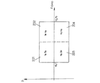
元の周波数帯域がSIBよりも広い場合、元の周波数帯域は、低い方の元の周波数帯域と高い方の元の周波数帯域との2つの部分に分割される。したがって、受信機3は、低い方の周波数帯域の変調信号と高い方の周波数帯域の変調信号から第2の選択を行う。この第2の選択の完了時に、受信機3は、元の衛星信号1に由来している4つの信号から1つを選択することになる。これら4つの信号のスペクトルは、図2に模式的に示していて、慣例によって、垂直偏波または水平偏波のスペクトルを、周波数軸の下部または上部にそれぞれ示している。したがって、元の周波数帯域が低い方の、変調された垂直偏波信号VeBa、元の周波数帯域が高い方の、変調された垂直偏波信号VeHa、元の周波数帯域が低い方の、変調された水平偏波信号HoBa、元の周波数帯域が高い方の、変調された垂直偏波信号HoHaが区別されて示されている。 If the original frequency band is wider than the SIB, the original frequency band is divided into two parts: a lower original frequency band and a higher original frequency band. Therefore, the receiver 3 performs the second selection from the modulated signal in the lower frequency band and the modulated signal in the higher frequency band. At the completion of this second selection, the receiver 3 will select one of the four signals originating from the original satellite signal 1. The spectrums of these four signals are schematically shown in FIG. 2, and the vertical polarization or horizontal polarization spectrum is conventionally shown at the lower part or the upper part of the frequency axis, respectively. Therefore, the modulated vertical polarization signal VeBa with the lower original frequency band, the modulated vertical polarization signal VeHa with the higher original frequency band, and the modulated signal with the lower original frequency band are modulated. The horizontal polarization signal HoBa and the modulated vertical polarization signal HoHa having the higher original frequency band are shown separately.
受信機3は、スイッチングマトリクスを介して切り替える前に、選択された信号の前処理を行う。この前処理は、選択されている信号の周波数を所定の混合周波数と混合して、SIBの前処理された信号を得ることである。低い方の元の周波数帯域の処理に一般的に使用される所定の混合周波数は従来9.75GHzであり、高い方の元の周波数帯域の処理に一般的に使用される所定の混合周波数は従来10.6GHzである。 The receiver 3 performs preprocessing of the selected signal before switching through the switching matrix. This pre-processing is to obtain the pre-processed signal of SIB by mixing the frequency of the selected signal with a predetermined mixing frequency. The predetermined mixing frequency commonly used for processing the lower original frequency band is conventionally 9.75 GHz, and the predetermined mixing frequency commonly used for processing the higher original frequency band is conventional. 10.6 GHz.
そのため、受信機3は、選択的にSIBに移動している前処理された信号VeBa、VeHa、HoBa、HoHaにそれぞれ由来している4つの信号を出力する。図2は、それぞれ201、202、203、204として参照される、元の衛星外部信号に含まれていた4つの信号VeBa、BeHa、HoBa、HoHaを示している。 Therefore, the receiver 3 outputs four signals each derived from preprocessed signals VeBa, VeHa, HoBa, and HoHa that are selectively moved to the SIB. FIG. 2 shows four signals VeBa, BeHa, HoBa, HoHa that were included in the original satellite external signal, referred to as 201, 202, 203, 204, respectively.
216、217、218として参照される同軸ケーブルは、各々が多くとも1つの前述の前処理された信号を搬送しており、もちろん同じ信号がいくつかの同軸ケーブルで搬送されることもある。受信機3内で、マイクロコントローラは、決められた前処理された信号をそれぞれ少なくとも1つの処理ユニット213、214、215に対して送信するように、処理ユニット213、214、215から受信した命令に基づいてスイッチングマトリクスを管理する。一般的に、そのようなスイッチングマトリクスは受信機3に内蔵されている。しかし、特定の衛星受信設備内では、スイッチングマトリクスは、受信機3に接続されている他のボックスの一部を構成していることもある。
The coaxial cables referred to as 216, 217, 218 each carry at most one of the aforementioned preprocessed signals, and of course, the same signal may be carried on several coaxial cables. Within the receiver 3, the microcontroller is responsive to the instructions received from the
各処理ユニット213、214、215は、各処理ユニット213、214、215を受信機3に接続している同軸ケーブル216、217、218によって送信された前処理された信号から抽出された1つまたは2つ以上の「有用な」信号を処理する役割がある。通常、「有用な信号」という表現は、所定の衛星チャネルに対応している信号を表す。
Each
衛星受信用設備の従来のアーキテクチャにおいては、処理ユニット213、214、215は互いに独立していて、互いに情報を交換しない。
In the conventional architecture of a satellite receiving facility, the
そのため、同一の衛星受信用設備の処理ユニットがSIBのデータを交換することができるようにする必要性は明らかである。特に、これらの処理ユニットは、映像形式つまり映画形式のデジタルデータを大容量記録媒体上に記録する機能、そのように記録されたデータを読み取る機能、電話網に処理ユニットを接続できるようにする機能、解読資格を管理する機能などさまざまな機能を提供することができる。 Therefore, it is clear that the processing unit of the same satellite reception facility must be able to exchange SIB data. In particular, these processing units have a function for recording digital data in a video format, that is, a movie format on a large-capacity recording medium, a function for reading such recorded data, and a function for connecting the processing unit to a telephone network. Various functions can be provided, such as the ability to manage decryption qualifications.
処理ユニットが他の処理ユニットによって提供される機能を使用する場合、新しいワイヤリンク、したがって新しい同軸ケーブルを取り付けることができる。この解決策の主な欠点には、取り付けのコスト、保守のコスト、および配線の見栄えが良くないことがある。また、マイクロコントローラによって実行される動作によって、ある処理ユニットから他の処理ユニットへ信号を送信することもできる。具体的には、マイクロコントローラは、処理ユニットから信号を受け取って保存し、同軸ケーブルを介して宛先の処理ユニットに信号を送信するために、信号を中継することができる。商標DiSEqCによって知られているプロトコル等のプロトコルのメッセージなどの低スループットの信号だけをおおむね22kHzの周波数でこのように処理ユニット間で交換してもよい。しかし、ある処理ユニットによって他の処理ユニットに送信される信号は、他の処理ユニットに送信するために中継される前に、受信機のマイクロコントローラによってまず受信され、それからデコードされ、最後に保存されるため、そのようなスループットは、音声信号と映像信号の送信などのアプリケーションで必要な量の情報の送信のためには十分に高くない。トランシーバを各処理ユニットに組み込むことによって、無線送信に基づいた解決策を使用することも可能である。しかし、この解決策には、機器の財務費用に関する欠点がある。さらに、衛星ベースのサービスを提供している運営業者は、このサービスに対するアクセスをこのサービスの契約者だけに限定して、契約者ではない契約者の隣人すべてがサービスにアクセスすることを除外する特に高価な手段を望んでいる。現在、このような保証をすることは、無線送信の分野では、非常に高価となる。 If the processing unit uses functions provided by other processing units, a new wire link and thus a new coaxial cable can be attached. The main drawbacks of this solution are the cost of installation, the cost of maintenance and the poor appearance of the wiring. Further, a signal can be transmitted from one processing unit to another processing unit by an operation executed by the microcontroller. Specifically, the microcontroller can receive and store the signal from the processing unit and relay the signal to transmit the signal to the destination processing unit via a coaxial cable. Only low throughput signals such as protocol messages such as the protocol known by the trademark DiSEqC may be exchanged between the processing units in this way at a frequency of approximately 22 kHz. However, a signal sent by one processing unit to another processing unit is first received by the receiver microcontroller before being relayed for transmission to the other processing unit, then decoded and finally stored. Therefore, such a throughput is not high enough for transmission of an amount of information necessary for applications such as transmission of audio signals and video signals. It is also possible to use a solution based on radio transmission by incorporating a transceiver in each processing unit. However, this solution has drawbacks related to the financial costs of the equipment. In addition, operators providing satellite-based services should limit access to this service only to subscribers of this service, excluding all non-subscriber neighbors accessing the service. I want an expensive means. Currently, making such a guarantee is very expensive in the field of wireless transmission.
そのため、同一の衛星受信用設備の処理ユニットが機能を共有できるようにする、衛星受信用設備内に配置される、設置が安価で容易なシステムに対する要求が明確に存在する。 Therefore, there is clearly a need for a system that is placed in a satellite reception facility that allows the processing units of the same satellite reception facility to share functions and that is inexpensive and easy to install.
本発明は、この要求を満たす解決策を提案することを目的としている。 The present invention aims to propose a solution that satisfies this need.
それに応じて、本発明の第1の実施態様は、
衛星信号を受信して、衛星信号に含まれている数個の外部信号から1つの外部信号を選択し、選択された外部信号を前処理する受信機と、
特に、対応するそれぞれのワイヤリンクを介して受信機に各々が接続されていて、衛星中間帯域つまりSIBと呼ばれるUHF周波数帯域で受信動作を行う複数の処理ユニットと、
前処理後の選択された外部信号を、対応するワイヤリンクを介して少なくとも1つの処理ユニットに切り替えるスイッチングマトリクスを備えている信号分配部と、
を有している衛星受信用設備内の信号分配方法において、
決められた第1の処理ユニットによってSIBで送信される内部信号を少なくとも1つの決められた第2の処理ユニットへ信号分配部を介して送信するようになっている少なくとも1つの接続(接続手段、接続部)が衛星受信用設備内に設けられていることを特徴とする信号分配方法を提案している。
Accordingly, the first embodiment of the present invention is:
A receiver that receives a satellite signal, selects one external signal from several external signals included in the satellite signal, and pre-processes the selected external signal;
In particular, a plurality of processing units each connected to a receiver via a corresponding respective wire link and performing a receiving operation in a satellite intermediate band, or UHF frequency band called SIB,
A signal distributor comprising a switching matrix for switching selected external signals after preprocessing to at least one processing unit via corresponding wire links;
In a signal distribution method in a satellite reception facility having
At least one connection (connection means) adapted to transmit an internal signal transmitted in SIB by a determined first processing unit to at least one determined second processing unit via a signal distributor; A signal distribution method is proposed in which the connection portion is provided in the satellite reception facility.
本発明の第2の実施態様は、第1の態様に記述されている方法を実施する信号分配部を提案している。 The second embodiment of the present invention proposes a signal distributor that implements the method described in the first aspect.
本発明の第3の実施態様は、第1の態様に記述されている方法を実施するシステムを提案している。 The third embodiment of the present invention proposes a system for implementing the method described in the first aspect.
本発明の第4の実施態様は、衛星信号の受信用の受信機と信号分配部を有している衛星受信用設備内の第3の実施態様の信号分配用システムで使用されるようになっている処理ユニットを提案している。処理ユニットは、ワイヤリンクを介して信号分配部に接続されていて、衛星中間帯域、つまりSIBと呼ばれているUHF周波数帯域の受信信号を処理する手段を有している。 The fourth embodiment of the present invention is used in the signal distribution system of the third embodiment in a satellite reception facility having a receiver for receiving satellite signals and a signal distribution unit. Proposed processing unit. The processing unit is connected to the signal distribution unit via a wire link, and has means for processing a received signal in a satellite intermediate band, that is, a UHF frequency band called SIB.
一実施態様では、処理ユニットは、信号のSIBで変調するようになっていて、そのように変調された信号をワイヤリンクを介して信号分配部に送信する信号変調ユニットをさらに有している。 In one embodiment, the processing unit further comprises a signal modulation unit adapted to modulate with the SIB of the signal and to transmit the signal thus modulated to the signal distributor over the wire link.
処理ユニットは、SIBとは別個で、SIBに実質的に隣接している周波数帯域の信号を変調するようになっていて、そのように変調された信号をワイヤリンクを介して信号分配部に送信する信号変調ユニットをさらに有していてもよい。 The processing unit is configured to modulate a signal in a frequency band that is separate from the SIB and substantially adjacent to the SIB, and transmits the modulated signal to the signal distribution unit via the wire link. It may further have a signal modulation unit.
処理ユニットは、セットトップボックスであってもよい。 The processing unit may be a set top box.
本発明のその他の態様、目的、利点は、添付図面を参照して以下で説明する実施形態の1つについての説明を読むことによって明らかになろう。 Other aspects, objects, and advantages of the present invention will become apparent upon reading the description of one of the embodiments described below with reference to the accompanying drawings.
本発明は、図面の助けによってさらによく理解されるであろう。 The invention will be better understood with the aid of the drawings.
さまざまな図において、同一のまたは同様の構成要素には同じ参照番号を付している。本明細書では、「外部信号」という用語は、衛星受信用設備の外部から受信した信号、つまり衛星の信号または衛星の信号に由来している信号を指し、「内部信号」という用語は、衛星受信用設備の内部で生成され送信される信号を指し、「内部接続」という用語は、処理ユニットによって出力されたSIB内に存在している周波数の内部信号を1つまたは2つ以上の処理ユニットに送信できるようにする接続を指す。 In the various figures, identical or similar components are provided with the same reference numerals. As used herein, the term “external signal” refers to a signal received from outside the satellite receiving facility, that is, a satellite signal or a signal derived from a satellite signal, and the term “internal signal” refers to a satellite signal. Refers to a signal generated and transmitted within a receiving facility, and the term “internal connection” refers to an internal signal of one or more processing units at a frequency present in the SIB output by the processing unit. A connection that allows you to send to.
最初に、本発明の実施形態の衛星受信用設備の機能ブロックを模式的に示している図3を参照する。受信機3は、元の衛星外部信号1に由来していて、それぞれ201、202、203、204として参照される外部信号VeBa、VeHa、HoBa、HoHaを入力として受信する前処理機能ブロック205を有している。このようにして受信された信号201、202、203、204は、信号分配部207に送信される前に、前処理機能ブロック205によって前処理される。信号分配部207は、受信機3に内蔵されていても、受信機3に単に接続されていてもよい。信号分配部207は、前処理された信号を入力として受信する。信号分配部207は、スイッチングマトリクス208と、スイッチングマトリクス208の出力を210、211、212として参照される信号分配部207のポートに接続する接続手段209を有している。このように、信号分配部207は、少なくとも2つのポートを互いに1つに直接接続することができるようになっている。
Reference is first made to FIG. 3, which schematically shows functional blocks of a satellite reception facility according to an embodiment of the present invention. The receiver 3 has a preprocessing function block 205 that receives external signals VeBa, VeHa, HoBa, and HoHa that are derived from the original satellite external signal 1 and are referred to as 201, 202, 203, and 204, respectively, as inputs. doing. The
以下の図では、波線の矢印は、処理ユニット213によって処理ユニット214に対して出力された制御信号の送信を表している。実線の矢印は、処理ユニット214から送信されたデータ信号の送信を表している。
In the following diagram, the wavy arrow represents the transmission of the control signal output by the
図4は、本発明の実施形態の2つの処理ユニット213、214を有している衛星受信用設備の一部示している。処理ユニット213、214のこの数は、説明を簡単にするための例である。本発明は、もちろん、多数の処理ユニットを有している衛星受信用設備に対して適用することができる。図4は、2本の同軸ケーブル216、217によって各々が2つの処理ユニット213と214にそれぞれ接続されている2つのポート210と211を有していることを示している信号分配部207を示している。前処理された信号306、307、308は、信号分配部207によって受信される。信号分配部207は、接続されている処理ユニットと同数のポートを有していることを示している。図4に示した例では、処理ユニット213は、復調器/チューナ301とMPEGプロトコルデコーダ302を有している装置である。この種類の装置(「セットトップボックス」)は、一般的にテレビ画面の前段に配置されている。処理ユニット214はたとえば、復調器/チューナと、MPEGプロトコルデコーダと、ハードディスク、CD−ROM、DVD−ROMなどの大容量メモリ303を通常有しているデジタルビデオレコーダである。処理ユニット214のような装置はDVR(「デジタルビデオレコーダ」を表す)と呼ばれている。処理ユニット214は、さらに参照番号316が付されている再変調器を有している。
FIG. 4 shows a part of a satellite reception facility having two processing
さらに、信号分配部207は、マイクロコントローラ310と、出力が313と314として参照されるスイッチングマトリクス208を有している。もちろん、受信機3内のそのような信号分配部207については、マイクロコントローラ310は、受信機3のマイクロコントローラとすることができる。処理ユニット214が前処理された信号306、307、308の1つを受信して、その信号に含まれているデータを保存する場合、処理ユニット214は、たとえば前述のDiSEqCプロトコルを使用して対応する制御メッセージを信号分配部207に送信する。マイクロコントローラ310は、このメッセージを処理し、要求された前処理された信号を対応する処理ユニット214に送信するようにスイッチングマトリクス208に対して指示する。処理ユニット214は、たとえば映画に対応しているデータをメモリ303に保存する。処理ユニット214は、それから受信の停止を指示する。
Further, the
たとえば、処理ユニット213が処理ユニット214のメモリ303に保存されている映画を読み出すときには、処理ユニット213はDiSEqCプロトコルによってデータの送信の要求メッセージを処理ユニット214に送信する。この要求メッセージは、同軸ケーブル216によって信号分配部207に送信される。マイクロコントローラ310は、この要求メッセージの宛先である処理ユニット214に送信するために、この要求メッセージを受信し、保存し、同軸ケーブル217上に中継する。ただし、制御プロトコルメッセージに対応している信号の周波数は通常約22kHzである。そのため、制御メッセージの交換は、マイクロコントローラ310の前述の処理によって行うことができる。要求メッセージを受信すると、処理ユニット214は関連するデータを、読出すことによってメモリ303から復元して、再変調器316によってSIB内に存在している周波数で再変調された信号でデータを送信する。再変調された信号は、信号分配部207のポート211に同軸ケーブル217を介して送信される。この信号分配部207において、ポート211からスイッチングマトリクス208に入力としてループしているフィードバック接続312によって、再変調された信号をスイッチングマトリクス208の入力部に送信することができる。したがって、同軸ケーブル216を介して処理ユニット213に送信されるように、再変調された信号をスイッチングマトリクス208の出力313に切り替えることができる。処理ユニット214に接続されている信号分配部207のポート211は「アドバンストポート」と呼ばれている。このようなアドバンストポートによって、他のすべてのポートと同じように、衛星から受信した外部信号の送信が可能になると共に、アドバンストポートに接続されている処理ユニット214による、SIBに存在している周波数の内部信号の1つまたは2つ以上の他の処理ユニットへの送信も可能になる。そのため、アドバンストポートは入出力ポートになる。そのような接続によって、SIBに存在し、たとえば映像データの送信が可能なスループットと同じかそれよりも大きい高スループットを有している周波数の信号を送信することができる。
For example, when the
本発明の前述の実施形態では、処理ユニット214のメモリ303のデータを内部的に送信している間は、2本の同軸ケーブル216、217のSIBの一部が使用される。従来は、前処理された衛星信号1を同軸ケーブル216、217上で送信するときには、SIB全体が占有されていた。そのため、処理ユニット214がメモリ303を「読み取っている」間、つまり図3の例で、映画が読み取られている間は、処理ユニット214も処理ユニット213も、外部からの衛星信号1を受信できなかった。
In the above-described embodiment of the present invention, part of the SIBs of the two
図5に示している本発明の好適な実施形態では、信号分配部207、より正確にはこの信号分配部207のアドバンストポート211は、SIBの一部分だけを占めている前処理された衛星外部信号を送信する手段を有している。その結果、SIBは、第1の周波数サブ帯域と第2の周波数サブ帯域に分割されている。第1の周波数サブ帯域は、前処理された信号の受信に使用される。したがって、第2の周波数サブ帯域は、ある処理ユニットから他の処理ユニットへの再変調された内部信号の送信に使用することができる。この機能は、フランス特許出願公開明細書第2835368号に詳細に記述されている。
In the preferred embodiment of the present invention shown in FIG. 5, the
具体的には、フランス特許出願公開明細書第2835368号は、前処理された様々な信号から有用な信号を抽出し、抽出された信号を同一の同軸ケーブルを介して同時に送信するために抽出された信号を組み合わせることが可能なシフトとフィルタリングの機能を有利に備えている受信機について説明している。したがって、このような機能を備えている受信機は、前処理された様々な信号に由来している、言い換えれば、偏波が異なる信号および/または元の周波数帯域がBaまたはHaの信号に由来している有用な外部信号を1つの同軸ケーブルを介して同時に要求する処理ユニットを実現することができる。この機能は、衛星チャネルルータ(つまりSCR)とバンドパスフィルタ(BPF)を有しているシステムに基づいている。衛星チャネルルータは、所定の混合周波数の関数として、前処理された信号の周波数帯域をシフトする周波数ミキサを有している。前処理され、切り替えられ、混合周波数によってシフトされた信号は、次に、必要としている処理ユニットが要求している有用な信号に対応している、言い換えれば、所与の衛星チャネルに対応している信号を抽出できるバンドパスフィルタを通過する。 Specifically, French Patent Application Publication No. 2835368 is extracted to extract useful signals from various preprocessed signals and transmit the extracted signals simultaneously over the same coaxial cable. A receiver is described which advantageously has the function of shifting and filtering that can combine the received signals. Therefore, a receiver having such a function is derived from various preprocessed signals, in other words, signals having different polarizations and / or signals having an original frequency band of Ba or Ha. It is possible to realize a processing unit that simultaneously requests useful external signals via a single coaxial cable. This function is based on a system having a satellite channel router (ie SCR) and a bandpass filter (BPF). The satellite channel router has a frequency mixer that shifts the frequency band of the preprocessed signal as a function of a predetermined mixing frequency. The signal that has been preprocessed, switched and shifted by the mixing frequency then corresponds to the useful signal required by the processing unit in need, in other words, corresponding to a given satellite channel. It passes through a band-pass filter that can extract the existing signal.
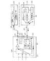
図5は、好適な実施形態による信号分配部を有している衛星受信用設備の一部を示している。本実施形態の信号分配部207は、図4に関して説明しているように、スイッチングマトリクス208にループ状に接続されているフィードバック接続312を有している。信号分配部207は、SCRとバンドパスフィルタによって実行されるシフトおよびフィルタリング機能401をアドバンストポート211上にさらに有している。このように、前処理され切り替えられている衛星信号1は、第1の周波数サブ帯域で送信されるようにシフトされフィルタリングされる。その結果、処理ユニット213は、処理ユニット214に対して第2の周波数サブ帯域で同時にデータを送信するのを指示することができる。送信は、図4で前述したのと同じように、マイクロコントローラ310の処理によって、処理ユニット213が要求することができる。本発明の実施形態では、処理ユニット213は、404として参照される再変調器を有している。制御信号は、同軸ケーブル216を介して信号分配部207へ送信される前に、再変調器404によってSIBに隣接している別個の周波数帯域で再変調される。信号分配部207は、ポート210で制御信号を受信し、処理ユニット214へ同軸ケーブル217上を送信する前に、402として参照される接続部を介して制御信号をポート211へ送信する。接続部402は、方向性カプラを有していて、210として参照されるポートを211として参照されるポートに接続している。この接続部402によって、高スループットの搬送波のUHF信号を送信することができる。一般に、処理ユニットは、SIBに存在している信号を処理することができる。900MHzと950MHzとの間に存在している周波数の信号を処理できる処理ユニットもある。処理ユニット213によって再変調された制御信号は、SIBに隣接した900MHzと950MHzとの間に存在している周波数帯域で送信されることが好ましい。このような接続部402によるこのような制御信号の送信によって、処理ユニット213、214間での命令の非常に高速な送信が可能になる。処理ユニット214から処理ユニット213への信号の送信は、図4の説明で前述した方法と同じ方法で実行することができる。
FIG. 5 shows part of a satellite reception facility having a signal distributor according to a preferred embodiment. As described with reference to FIG. 4, the
図6は、処理ユニット214が外部信号51を受信し、同時に内部信号52を処理ユニット213に送信したときの、図5の典型的な実施形態で403として参照されるSIBの使用状態を示している。51として参照される信号は、衛星外部信号に由来している前処理された信号に対応し、52として参照される信号は内部信号に対応している。これらの2つの信号は、以前に定められているSIB内に存在している別個の周波数サブ帯域を占めている。そのため、これらの2つの信号を同時に送信することができる。さらに、処理ユニット213から送信され、53として参照される制御信号は、SIBの外側の、しかし、900MHzと950MHzとの間に存在することが好ましい、隣接している周波数帯域内に存在するものとして示されている。
FIG. 6 shows the usage of the SIB referenced as 403 in the exemplary embodiment of FIG. 5 when the
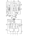
図7は、2つの処理ユニット213と214を有している衛星受信用設備の一部を示していて、ここでは、信号分配部207のアドバンストポート211によって処理ユニット214は、直接読み取るために(たとえば、この処理ユニット214に接続されたテレビ画面上へ表示するために)衛星信号1に由来している外部信号を受信すること、他の外部信号をメモリ303に記録すること、およびメモリ303から復元したデータに基づいてSIBに存在している周波数で内部信号を処理ユニット213に送信することができる。読み取られる信号と記録される信号は、元の衛星信号1に由来している2つの別個の前処理された信号に由来している場合もある。具体的には、本実施形態では、信号分配部207のアドバンストポート211は、スイッチングマトリクス208の2つの出力、したがって、異なる場合もある2つの前処理された信号に関連付けられていて、これらの2つの信号の各々は、同一の同軸ケーブル217上を送信される前に、シフトおよびフィルタリング機能401によってシフトされ、それからフィルタリングされる。
FIG. 7 shows a part of a satellite reception facility having two processing
図8は、前述の例の同軸ケーブル217の、403として参照されるSIBの使用状態を示している。71(または再生(Play)を表すP)として参照される信号は、直接読み取る外部信号に対応していて、72(または記録(Record)を表すR)として参照される信号は、記録される外部信号に対応していて、52として参照される信号は、処理ユニット214から処理ユニット213へ送信される内部信号に対応している。これらの信号は、前述したSIBの内部に周波数によって割り当てられている。元の外部信号に由来している信号71と72は第1の周波数サブ帯域内で送信され、内部信号52は第2の周波数サブ帯域内で送信され、これら2つの周波数サブ帯域は別個である。制御信号53も図6に示している。
FIG. 8 shows a usage state of the SIB referred to as 403 of the
もちろん、本発明の様々な実施形態は、多数の処理ユニットを有していて、処理ユニットの数に対応している多数のポートを有していることを示している信号分配部を備えている衛星受信用設備に関しても容易に実施することができる。さらに、数個のアドバンストポートを有している本発明の実施形態による信号分配部も考えられる。本発明の好適な実施形態では、そのような信号分配部のポートは、シフトおよびフィルタリング機能401をさらに内蔵していてもよい。
Of course, various embodiments of the present invention include a signal distribution section having multiple processing units, indicating that there are multiple ports corresponding to the number of processing units. It can also be easily implemented with respect to a satellite reception facility. Furthermore, a signal distribution unit according to an embodiment of the present invention having several advanced ports is also conceivable. In a preferred embodiment of the present invention, such a signal distributor port may further incorporate a shift and
図9は、接続手段209が前述の実施形態とは異なる本発明の実施形態の衛星受信用設備の一部を示している。本実施形態では、スイッチングマトリクス208のすべての出力が、シフトおよびフィルタリング機能401を備えている。その結果、すべての前処理され切り替えられた信号は、第1の周波数サブ帯域で送信するようにシフトされフィルタリングされる。したがって、スイッチングマトリクス208のすべての出力を信号分配部207の1つのポート801に結合することができる。処理ユニット214は、データ要求信号を受信すると、メモリ303から読み取られたデータを復元し、これらのデータを決められた第2の周波数サブ帯域内で同軸ケーブル217を介して送信できるようにRF信号の形態で再変調する。信号分配部207は、このようにして処理ユニット214から受信され、決められた第2の周波数サブ帯域で再変調されている内部信号を反射するインピーダンスを有している。したがって、処理ユニット214によって送信された信号は、信号分配部207によって反射され、その結果、802として参照される電力分配器を介して信号分配部207の出力としてすべての同軸ケーブル216、217上を再度送信される。したがって、決められたインピーダンスを有しているケーブル上での信号の反射によって処理ユニット214から処理ユニット213への内部接続が成立する。インピーダンスの値は、処理ユニット214によって出力される信号の決められた第2の周波数サブ帯域での再変調に対して、反射係数が非零になるように選択されている。処理ユニット213によって処理ユニット214に対して前述のように送信された制御信号は、図4の例で説明したようにマイクロコントローラ310の処理を経て送信することができる。本発明の好適な実施形態では、インピーダンスの値は、SIBに存在している決められた第3の周波数サブ帯域について反射係数が非零になるように選択されている。したがって、制御信号は、同軸ケーブル216上を送信される前に、処理ユニット213の再変調器404によって第3の周波数サブ帯域内で再変調される。
FIG. 9 shows a part of the satellite reception facility of the embodiment of the present invention in which the connecting means 209 is different from the above-described embodiment. In this embodiment, all outputs of the switching
図10は、そのような衛星受信用設備でのSIBの使用状態を示している。衛星信号1に由来している4つの信号B1、B2、B3、B4は、処理ユニット214から処理ユニット213への内部信号52の送信と同時に第1の周波数サブ帯域で送信される。内部信号52は、第2の周波数サブ帯域内で処理ユニット214によって送信される。したがって、ポート801へ接続されている同軸ケーブル216、217は、外部信号B1、B2、B3、B4と内部信号52を同時に送信することができる。
FIG. 10 shows the state of use of the SIB in such a satellite reception facility. Four signals B 1, B 2, B 3, B 4 derived from the satellite signal 1 are transmitted in the first frequency subband simultaneously with the transmission of the
本発明の実施形態の同一の衛星受信用設備の処理ユニット213、214を多くの機能において共有することができる。前述の例では、衛星受信用設備の処理ユニット214はさらに、デジタルビデオレコーダと同等の方法で動作する。そのため、処理ユニット214が処理ユニット213に送信するデータは、メモリ303から読み出されたデータとして記載されている。もちろん、処理ユニット214が処理ユニット213に送信する信号に含まれているデータは、衛星受信用設備外のネットワークなどのメモリ303以外に由来する場合もある。具体的には、処理ユニット214は、たとえば電話網などの1つまたは2つ以上の外部ネットワークへ接続されるモジュールを備えることができ、そのため、処理ユニット214から処理ユニット213へ送信される内部信号に含まれるデータは、1つまたは2つ以上の外部のネットワークに由来する場合もある。さらに一般的には、同一の衛星受信用設備の処理ユニットを、214として参照される処理ユニットを介して外部のネットワークに接続することもできる。本発明の実施形態の他の興味深い用途は、解読資格の管理機能の共有である。具体的には、処理ユニット214に、たとえば衛星受信用設備の各処理ユニットに対応した暗号鍵を管理、保存する機能を持たせることができる。したがって、処理ユニットの電源が投入されるすぐに、処理ユニットは処理ユニットの解読資格に関する情報をこの情報を保存している処理ユニット214に要求する。
The
本発明の実施形態に関係なく、処理ユニットは、その他の1つまたは2つ以上の処理ユニットがスレーブ処理ユニットとして動作するのに対して、共有され、マスタ処理ユニットとして動作する機能を有することができると有利である。 Regardless of the embodiment of the present invention, the processing unit may have a function of being shared and operating as a master processing unit, while one or more other processing units operate as slave processing units. It is advantageous if possible.
本発明の利点は、衛星受信用設備内の本発明の実施形態の信号分配部が非常に容易にそして非常に低い生産コストで製造可能なことである。さらに、本発明の他の利点は、本発明の実施形態の信号分配部の取り付けが非常に容易なことである。具体的には、そのような信号分配部は、受信機(つまりLNB)内に組み込むことが可能で、そのため、たとえばユーザが処理ユニットを自身の衛星受信用設備内に追加したい場合にすでに実施されているように、LNBを変更すれば十分である。そのような信号分配部は、受信機に接続されているボックスに組み込むことも可能で、そのようなボックスの交換も同様に容易である。その結果、本発明の実施によれば、これまでの衛星受信用設備と、同軸ケーブル形式のワイヤリンクであろうと他の形式のワイヤリンクであろうと、既存のケーブル配線は変更する必要がない。 An advantage of the present invention is that the signal distribution part of the embodiment of the present invention in a satellite receiving facility can be manufactured very easily and at a very low production cost. Furthermore, another advantage of the present invention is that it is very easy to install the signal distribution part of the embodiment of the present invention. In particular, such a signal distributor can be incorporated in the receiver (ie LNB), so that it is already implemented, for example, when a user wants to add a processing unit in his satellite reception facility. As shown, it is sufficient to change the LNB. Such a signal distributor can also be incorporated in a box connected to the receiver, and replacement of such a box is equally easy. As a result, according to the implementation of the present invention, it is not necessary to change the existing cabling, whether it is a conventional satellite receiving facility or a wire link of a coaxial cable type or another type of wire link.
さらに、処理ユニットがSIB内で動作する場合、従来の衛星受信用設備は、この周波数帯域で送信される信号を扱うことができる部品をすでに有している。そのため、本発明の実施形態の重要な利点は、そのような衛星受信設備の既存の部品を使用することで、本発明の実施形態を低コストで実施可能なことである。 Furthermore, when the processing unit operates in the SIB, the conventional satellite receiving equipment already has components that can handle signals transmitted in this frequency band. Therefore, an important advantage of the embodiments of the present invention is that the embodiments of the present invention can be implemented at low cost by using the existing components of such satellite receiving equipment.
1 衛星信号
2 パラボラアンテナ
3 受信機
4〜6 出力ポート
51 外部信号
52 内部信号
53 制御信号
71 直接読み取られる外部信号
72 記録される外部信号
201〜204 信号
205 前処理用機能ブロック
207 信号分配部
208 スイッチングマトリクス
209 接続手段
210〜212、801 ポート
213〜215 処理ユニット
216〜218 同軸ケーブル
301 復調器/チューナ
302 MPEGプロトコルデコーダ
303 メモリ
306〜308 前処理されている信号
310 マイクロコントローラ
312 フィードバック接続
313〜314 出力
316、404 再変調器
401 フィルタリング機能
402 接続
403 SIB
802 電力分配器
DESCRIPTION OF SYMBOLS 1 Satellite signal 2 Parabolic antenna 3 Receiver 4-6
802 Power distributor
Claims (25)
特に、対応するそれぞれのワイヤリンク(216、217、218)を介して前記受信機(3)に各々が接続されていて、衛星中間帯域つまりSIBと呼ばれるUHF周波数帯域で受信動作を行う複数の処理ユニット(213、214、215)と、
前記前処理後の選択された外部信号を、前記対応するワイヤリンク(216、217、218)を介して少なくとも1つの前記処理ユニット(213、214、215)に切り替えるスイッチングマトリクス(208)を備えている信号分配部(207)と、
を有している衛星受信用設備内の信号分配方法において、
決められた第1の前記処理ユニット(214)によって前記SIBで送信される内部信号を少なくとも1つの決められた第2の前記処理ユニット(213)へ前記信号分配部(207)を介して送信するようになっている少なくとも1つの内部接続が前記衛星受信用設備の内部に設けられていることを特徴とする信号分配方法。 A receiver (3) that receives the satellite signal (1), selects one external signal from several external signals included in the satellite signal (1), and pre-processes the selected external signal When,
In particular, a plurality of processes each connected to the receiver (3) via corresponding wire links (216, 217, 218) and performing a receiving operation in the UHF frequency band called SIB or SIB. Units (213, 214, 215);
A switching matrix (208) for switching selected pre-processed external signals to at least one of the processing units (213, 214, 215) via the corresponding wire links (216, 217, 218); A signal distribution unit (207),
In a signal distribution method in a satellite reception facility having
An internal signal transmitted by the SIB by the determined first processing unit (214) is transmitted to at least one determined second processing unit (213) via the signal distribution unit (207). A signal distribution method, characterized in that at least one internal connection is provided inside the satellite reception facility.
a)前記第2の処理ユニット(213)が、決められた制御プロトコルによってデータ読み取り要求を前記第1の処理ユニット(214)に送信するステップと、
b)前記第1の処理ユニット(214)が前記データメモリ(303)内のデータを復元して、前記データを含んだ内部信号を前記内部接続を介して前記第2の処理ユニット(213)に送信するステップと、
c)前記第2の処理ユニット(213)が前記データを受信し処理するステップと、
をさらに有する、請求項1から6のいずれか1項に記載の信号分配方法。 The first processing unit (214) has a data memory (303),
a) the second processing unit (213) sending a data read request to the first processing unit (214) according to a determined control protocol;
b) The first processing unit (214) restores the data in the data memory (303), and an internal signal including the data is sent to the second processing unit (213) via the internal connection. Sending, and
c) the second processing unit (213) receiving and processing the data;
The signal distribution method according to claim 1, further comprising:
a)前記第2の処理ユニット(213)が、決められた制御プロトコルによって前記外部ネットワークへの接続命令を前記第1の処理ユニット(214)に送信するステップと、
b)前記第1の処理ユニット(214)が前記接続命令を実行するステップと、
c)前記第2の処理ユニット(213)が前記内部接続と前記第1の処理ユニット(214)を介して前記外部ネットワークとデータを交換するステップと、
をさらに有する、請求項1から7のいずれか1項に記載の信号分配方法。 The first processing unit (214) comprises a connection module adapted to connect to a network external to the satellite reception facility;
a) the second processing unit (213) sending a connection command to the external network to the first processing unit (214) according to a determined control protocol;
b) the first processing unit (214) executing the connection instruction;
c) the second processing unit (213) exchanging data with the external network via the internal connection and the first processing unit (214);
The signal distribution method according to claim 1, further comprising:
各外部信号を受信する入力部と、
対応するそれぞれのワイヤリンク(216、217、218)を介して前記処理ユニット(213、214、215)の1つにそれぞれ接続されるようになっているポート(210、211、212)と、
スイッチングマトリクス(208)と、
前記スイッチングマトリクス(208)の出力を前記ポート(210、211、212)に接続する接続手段(209)と、
を有する信号分配部において、
前記接続手段(209)は、決められた第1の前記処理ユニット(214)によって前記SIBで送信された内部信号を少なくとも1つの決められた第2の前記処理ユニット(213)へ該信号分配部(207)を介して送信するようになっている少なくとも1つの内部接続を前記衛星受信用設備内に備えるようになっていることを特徴とする信号分配部。 It is used in a satellite reception facility in which a plurality of processing units (213, 214, 215) that perform reception operations in a satellite intermediate band, that is, a UHF frequency band called SIB,
An input unit for receiving each external signal;
Ports (210, 211, 212) adapted to be connected to one of said processing units (213, 214, 215) via corresponding respective wire links (216, 217, 218);
A switching matrix (208);
Connection means (209) for connecting the output of the switching matrix (208) to the ports (210, 211, 212);
In the signal distribution unit having
The connection means (209) transmits the internal signal transmitted by the SIB by the determined first processing unit (214) to at least one determined second processing unit (213). (207) A signal distribution unit characterized in that at least one internal connection adapted to transmit via (207) is provided in the satellite reception facility.
特に、対応しているそれぞれのワイヤリンク(216、217、218)を介して前記受信機(3)に各々が接続されている複数の処理ユニット(213、214、215)と、
を有する衛星受信用設備内の信号分配用システムにおいて、
請求項9から14のいずれか1項に記載の信号分配部(207)をさらに有していることを特徴とする信号分配用システム。 A receiver (3) that receives a satellite signal (1), selects one external signal from several external signals included in the satellite signal (1), and pre-processes the selected external signal; ,
In particular, a plurality of processing units (213, 214, 215) each connected to the receiver (3) via respective corresponding wire links (216, 217, 218);
In a signal distribution system in a satellite reception facility having:
15. A signal distribution system further comprising the signal distribution unit (207) according to any one of claims 9 to 14.
A signal in a frequency band that is separate from the SIB and substantially adjacent to the SIB is modulated, and the signal thus modulated is transmitted to the signal distribution unit (via the wire link 6). 25. The set top box of claim 23 or 24, further comprising a signal modulation unit (404) for transmission to 207).
Applications Claiming Priority (1)
| Application Number | Priority Date | Filing Date | Title |
|---|---|---|---|
| FR0400502 | 2004-01-20 |
Publications (2)
| Publication Number | Publication Date |
|---|---|
| JP2005210724A true JP2005210724A (en) | 2005-08-04 |
| JP2005210724A5 JP2005210724A5 (en) | 2008-03-06 |
Family
ID=34630649
Family Applications (1)
| Application Number | Title | Priority Date | Filing Date |
|---|---|---|---|
| JP2005011616A Pending JP2005210724A (en) | 2004-01-20 | 2005-01-19 | Distribution method and system within satellite receiving equipment |
Country Status (4)
| Country | Link |
|---|---|
| US (1) | US7577401B2 (en) |
| EP (1) | EP1558035B1 (en) |
| JP (1) | JP2005210724A (en) |
| DE (1) | DE602005007392D1 (en) |
Cited By (1)
| Publication number | Priority date | Publication date | Assignee | Title |
|---|---|---|---|---|
| JP2007528671A (en) * | 2004-03-09 | 2007-10-11 | トムソン ライセンシング | Set-top box apparatus and method |
Families Citing this family (2)
| Publication number | Priority date | Publication date | Assignee | Title |
|---|---|---|---|---|
| US7814527B2 (en) | 2005-04-12 | 2010-10-12 | Thomson Licensing | Device and process for pairing a master decoder and slave decoders and reception system incorporating said device |
| BRPI0823043A2 (en) * | 2008-09-26 | 2015-07-28 | Thomson Licensing | Signal Transmission Control Method for Multiple Devices |
Citations (4)
| Publication number | Priority date | Publication date | Assignee | Title |
|---|---|---|---|---|
| JPH09102917A (en) * | 1995-10-04 | 1997-04-15 | Pioneer Electron Corp | Signal reproducing device |
| JP2000232462A (en) * | 1999-02-10 | 2000-08-22 | Showa Electric Wire & Cable Co Ltd | Home network system |
| JP2002354450A (en) * | 2001-05-28 | 2002-12-06 | Matsushita Electric Ind Co Ltd | Remote operating system of stb |
| JP2003051833A (en) * | 2001-08-06 | 2003-02-21 | Synclayer Inc | Indoor communication system and relay device |
Family Cites Families (13)
| Publication number | Priority date | Publication date | Assignee | Title |
|---|---|---|---|---|
| US5760822A (en) * | 1996-01-30 | 1998-06-02 | Lucent Technologies Inc. | Central node converter for local network having single coaxial cable |
| TW322632B (en) * | 1996-10-14 | 1997-12-11 | Vanguard Int Semiconduct Corp | Electrostatic discharge protection device for integrated circuit input/output port |
| DE19749120C2 (en) * | 1997-11-06 | 2002-07-18 | Kathrein Werke Kg | Satellite reception system and associated method for operating an antenna reception system |
| KR20010034333A (en) * | 1998-01-23 | 2001-04-25 | 와다 아끼히로 | Accounting apparatus, accounting system, and accounting card |
| WO2001017143A1 (en) * | 1999-08-27 | 2001-03-08 | Koninklijke Philips Electronics N.V. | In-home network using an existing coaxial cable installation |
| US6826647B1 (en) * | 2000-05-02 | 2004-11-30 | Communications-Applied Technology Co., Inc. | Voice operated communications interface |
| DE20008239U1 (en) * | 2000-05-10 | 2001-06-13 | Resch Electronic Innovation Gm | Multiswitch for satellite intermediate frequency distribution |
| WO2002065780A1 (en) * | 2001-02-14 | 2002-08-22 | Satellite Accessories, Llc | Broadcast television and satellite signal switching system and method for telephony signal insertion |
| US7130576B1 (en) * | 2001-11-07 | 2006-10-31 | Entropic Communications, Inc. | Signal selector and combiner for broadband content distribution |
| DE10155481A1 (en) * | 2001-11-13 | 2003-05-28 | Fachhochschule Dortmund | Device for controlling/monitoring release of reception signals at domestic cable distribution system connection points has central control unit directly connected to connection points |
| FR2835368A1 (en) * | 2002-01-29 | 2003-08-01 | St Microelectronics Sa | TRANSMISSION OF SIGNALS ON A COAXIAL CABLE |
| JP3888239B2 (en) * | 2002-06-20 | 2007-02-28 | 日本ビクター株式会社 | Digital audio processing method and apparatus, and computer program |
| WO2004038965A1 (en) * | 2002-10-23 | 2004-05-06 | Thomson Licensing Sa | Radio signal distribution device and reception system comprising said device |
-
2005
- 2005-01-12 EP EP05290076A patent/EP1558035B1/en not_active Expired - Fee Related
- 2005-01-12 DE DE602005007392T patent/DE602005007392D1/en not_active Expired - Fee Related
- 2005-01-19 US US11/040,169 patent/US7577401B2/en not_active Expired - Fee Related
- 2005-01-19 JP JP2005011616A patent/JP2005210724A/en active Pending
Patent Citations (4)
| Publication number | Priority date | Publication date | Assignee | Title |
|---|---|---|---|---|
| JPH09102917A (en) * | 1995-10-04 | 1997-04-15 | Pioneer Electron Corp | Signal reproducing device |
| JP2000232462A (en) * | 1999-02-10 | 2000-08-22 | Showa Electric Wire & Cable Co Ltd | Home network system |
| JP2002354450A (en) * | 2001-05-28 | 2002-12-06 | Matsushita Electric Ind Co Ltd | Remote operating system of stb |
| JP2003051833A (en) * | 2001-08-06 | 2003-02-21 | Synclayer Inc | Indoor communication system and relay device |
Cited By (2)
| Publication number | Priority date | Publication date | Assignee | Title |
|---|---|---|---|---|
| JP2007528671A (en) * | 2004-03-09 | 2007-10-11 | トムソン ライセンシング | Set-top box apparatus and method |
| JP4852529B2 (en) * | 2004-03-09 | 2012-01-11 | トムソン ライセンシング | Set-top box apparatus and method |
Also Published As
| Publication number | Publication date |
|---|---|
| EP1558035A1 (en) | 2005-07-27 |
| EP1558035B1 (en) | 2008-06-11 |
| US20050227613A1 (en) | 2005-10-13 |
| US7577401B2 (en) | 2009-08-18 |
| DE602005007392D1 (en) | 2008-07-24 |
Similar Documents
| Publication | Publication Date | Title |
|---|---|---|
| JP3256457B2 (en) | Central node conversion device and method for communication networks | |
| US5649318A (en) | Apparatus for converting an analog c-band broadcast receiver into a system for simultaneously receiving analog and digital c-band broadcast television signals | |
| JP3827518B2 (en) | Home network system | |
| US6169570B1 (en) | Two-way information transmission system, two-way information method, and subscriber terminal device | |
| CN102450008B (en) | Satellite signal distribution | |
| US6401243B1 (en) | Two-way information transmission system, two-way information transmission method, and subscriber terminal | |
| EP1920601B1 (en) | Multiroom point of deployment module | |
| US5943047A (en) | Two-way information transmission system, two-way information transmission method and subscriber terminal device | |
| US6922845B2 (en) | Multi-processor DVR | |
| US6023458A (en) | Method and system for distributing subscriber services using wireless bidirectional broadband loops | |
| US20040107436A1 (en) | Digital broadcast signal distribution system and subscriber terminal | |
| JP2000511734A (en) | Program guide for DBS and cable TV | |
| CN101548523A (en) | Remote access to internet protocol television by enabling place shifting utilizing a telephone company network | |
| US9936171B2 (en) | Network fraud prevention via registration and verification | |
| US7987486B2 (en) | System architecture for control and signal distribution on coaxial cable | |
| CA2621049C (en) | Frequency translation module discovery and configuration | |
| CN104221329A (en) | Apparatus and method for providing operational status for multiple communication networks | |
| US20080046947A1 (en) | Digital Media Server for Multiple Digital Tv Appliances Utilizing Native Signals Carried on Coaxial Home Wiring Networks | |
| US7900230B2 (en) | Intelligent two-way switching network | |
| US20040133911A1 (en) | Subscriber network in a satellite system | |
| JP2005210724A (en) | Distribution method and system within satellite receiving equipment | |
| JP2003274305A (en) | Digital broadcast receiver and digital broadcasting system | |
| WO2002052850A1 (en) | Distributed digital television system and related method | |
| JPH10135857A (en) | Receiver for cs digital multi-channel broadcasting | |
| KR20040108290A (en) | Digital satellite broadcasting receiver |
Legal Events
| Date | Code | Title | Description |
|---|---|---|---|
| A521 | Written amendment |
Free format text: JAPANESE INTERMEDIATE CODE: A523 Effective date: 20080121 |
|
| A621 | Written request for application examination |
Free format text: JAPANESE INTERMEDIATE CODE: A621 Effective date: 20080121 |
|
| A131 | Notification of reasons for refusal |
Free format text: JAPANESE INTERMEDIATE CODE: A131 Effective date: 20110119 |
|
| A02 | Decision of refusal |
Free format text: JAPANESE INTERMEDIATE CODE: A02 Effective date: 20110629 |