JP2005210080A - Temperature-control method and temperature-control device - Google Patents
Temperature-control method and temperature-control device Download PDFInfo
- Publication number
- JP2005210080A JP2005210080A JP2004344150A JP2004344150A JP2005210080A JP 2005210080 A JP2005210080 A JP 2005210080A JP 2004344150 A JP2004344150 A JP 2004344150A JP 2004344150 A JP2004344150 A JP 2004344150A JP 2005210080 A JP2005210080 A JP 2005210080A
- Authority
- JP
- Japan
- Prior art keywords
- temperature
- refrigerant
- path
- flow path
- circulation
- Prior art date
- Legal status (The legal status is an assumption and is not a legal conclusion. Google has not performed a legal analysis and makes no representation as to the accuracy of the status listed.)
- Pending
Links
Images


Classifications
-
- C—CHEMISTRY; METALLURGY
- C23—COATING METALLIC MATERIAL; COATING MATERIAL WITH METALLIC MATERIAL; CHEMICAL SURFACE TREATMENT; DIFFUSION TREATMENT OF METALLIC MATERIAL; COATING BY VACUUM EVAPORATION, BY SPUTTERING, BY ION IMPLANTATION OR BY CHEMICAL VAPOUR DEPOSITION, IN GENERAL; INHIBITING CORROSION OF METALLIC MATERIAL OR INCRUSTATION IN GENERAL
- C23C—COATING METALLIC MATERIAL; COATING MATERIAL WITH METALLIC MATERIAL; SURFACE TREATMENT OF METALLIC MATERIAL BY DIFFUSION INTO THE SURFACE, BY CHEMICAL CONVERSION OR SUBSTITUTION; COATING BY VACUUM EVAPORATION, BY SPUTTERING, BY ION IMPLANTATION OR BY CHEMICAL VAPOUR DEPOSITION, IN GENERAL
- C23C16/00—Chemical coating by decomposition of gaseous compounds, without leaving reaction products of surface material in the coating, i.e. chemical vapour deposition [CVD] processes
- C23C16/44—Chemical coating by decomposition of gaseous compounds, without leaving reaction products of surface material in the coating, i.e. chemical vapour deposition [CVD] processes characterised by the method of coating
- C23C16/46—Chemical coating by decomposition of gaseous compounds, without leaving reaction products of surface material in the coating, i.e. chemical vapour deposition [CVD] processes characterised by the method of coating characterised by the method used for heating the substrate
- C23C16/463—Cooling of the substrate
-
- C—CHEMISTRY; METALLURGY
- C23—COATING METALLIC MATERIAL; COATING MATERIAL WITH METALLIC MATERIAL; CHEMICAL SURFACE TREATMENT; DIFFUSION TREATMENT OF METALLIC MATERIAL; COATING BY VACUUM EVAPORATION, BY SPUTTERING, BY ION IMPLANTATION OR BY CHEMICAL VAPOUR DEPOSITION, IN GENERAL; INHIBITING CORROSION OF METALLIC MATERIAL OR INCRUSTATION IN GENERAL
- C23C—COATING METALLIC MATERIAL; COATING MATERIAL WITH METALLIC MATERIAL; SURFACE TREATMENT OF METALLIC MATERIAL BY DIFFUSION INTO THE SURFACE, BY CHEMICAL CONVERSION OR SUBSTITUTION; COATING BY VACUUM EVAPORATION, BY SPUTTERING, BY ION IMPLANTATION OR BY CHEMICAL VAPOUR DEPOSITION, IN GENERAL
- C23C16/00—Chemical coating by decomposition of gaseous compounds, without leaving reaction products of surface material in the coating, i.e. chemical vapour deposition [CVD] processes
- C23C16/44—Chemical coating by decomposition of gaseous compounds, without leaving reaction products of surface material in the coating, i.e. chemical vapour deposition [CVD] processes characterised by the method of coating
- C23C16/4411—Cooling of the reaction chamber walls
-
- C—CHEMISTRY; METALLURGY
- C23—COATING METALLIC MATERIAL; COATING MATERIAL WITH METALLIC MATERIAL; CHEMICAL SURFACE TREATMENT; DIFFUSION TREATMENT OF METALLIC MATERIAL; COATING BY VACUUM EVAPORATION, BY SPUTTERING, BY ION IMPLANTATION OR BY CHEMICAL VAPOUR DEPOSITION, IN GENERAL; INHIBITING CORROSION OF METALLIC MATERIAL OR INCRUSTATION IN GENERAL
- C23C—COATING METALLIC MATERIAL; COATING MATERIAL WITH METALLIC MATERIAL; SURFACE TREATMENT OF METALLIC MATERIAL BY DIFFUSION INTO THE SURFACE, BY CHEMICAL CONVERSION OR SUBSTITUTION; COATING BY VACUUM EVAPORATION, BY SPUTTERING, BY ION IMPLANTATION OR BY CHEMICAL VAPOUR DEPOSITION, IN GENERAL
- C23C16/00—Chemical coating by decomposition of gaseous compounds, without leaving reaction products of surface material in the coating, i.e. chemical vapour deposition [CVD] processes
- C23C16/44—Chemical coating by decomposition of gaseous compounds, without leaving reaction products of surface material in the coating, i.e. chemical vapour deposition [CVD] processes characterised by the method of coating
- C23C16/46—Chemical coating by decomposition of gaseous compounds, without leaving reaction products of surface material in the coating, i.e. chemical vapour deposition [CVD] processes characterised by the method of coating characterised by the method used for heating the substrate
-
- F—MECHANICAL ENGINEERING; LIGHTING; HEATING; WEAPONS; BLASTING
- F25—REFRIGERATION OR COOLING; COMBINED HEATING AND REFRIGERATION SYSTEMS; HEAT PUMP SYSTEMS; MANUFACTURE OR STORAGE OF ICE; LIQUEFACTION SOLIDIFICATION OF GASES
- F25D—REFRIGERATORS; COLD ROOMS; ICE-BOXES; COOLING OR FREEZING APPARATUS NOT OTHERWISE PROVIDED FOR
- F25D17/00—Arrangements for circulating cooling fluids; Arrangements for circulating gas, e.g. air, within refrigerated spaces
- F25D17/02—Arrangements for circulating cooling fluids; Arrangements for circulating gas, e.g. air, within refrigerated spaces for circulating liquids, e.g. brine
-
- H—ELECTRICITY
- H01—ELECTRIC ELEMENTS
- H01J—ELECTRIC DISCHARGE TUBES OR DISCHARGE LAMPS
- H01J37/00—Discharge tubes with provision for introducing objects or material to be exposed to the discharge, e.g. for the purpose of examination or processing thereof
- H01J37/32—Gas-filled discharge tubes
- H01J37/32431—Constructional details of the reactor
- H01J37/32458—Vessel
- H01J37/32522—Temperature
-
- H—ELECTRICITY
- H01—ELECTRIC ELEMENTS
- H01J—ELECTRIC DISCHARGE TUBES OR DISCHARGE LAMPS
- H01J37/00—Discharge tubes with provision for introducing objects or material to be exposed to the discharge, e.g. for the purpose of examination or processing thereof
- H01J37/32—Gas-filled discharge tubes
- H01J37/32431—Constructional details of the reactor
- H01J37/32715—Workpiece holder
- H01J37/32724—Temperature
-
- H—ELECTRICITY
- H01—ELECTRIC ELEMENTS
- H01L—SEMICONDUCTOR DEVICES NOT COVERED BY CLASS H10
- H01L21/00—Processes or apparatus adapted for the manufacture or treatment of semiconductor or solid state devices or of parts thereof
- H01L21/67—Apparatus specially adapted for handling semiconductor or electric solid state devices during manufacture or treatment thereof; Apparatus specially adapted for handling wafers during manufacture or treatment of semiconductor or electric solid state devices or components ; Apparatus not specifically provided for elsewhere
- H01L21/67005—Apparatus not specifically provided for elsewhere
- H01L21/67242—Apparatus for monitoring, sorting or marking
- H01L21/67248—Temperature monitoring
-
- F—MECHANICAL ENGINEERING; LIGHTING; HEATING; WEAPONS; BLASTING
- F25—REFRIGERATION OR COOLING; COMBINED HEATING AND REFRIGERATION SYSTEMS; HEAT PUMP SYSTEMS; MANUFACTURE OR STORAGE OF ICE; LIQUEFACTION SOLIDIFICATION OF GASES
- F25B—REFRIGERATION MACHINES, PLANTS OR SYSTEMS; COMBINED HEATING AND REFRIGERATION SYSTEMS; HEAT PUMP SYSTEMS
- F25B2700/00—Sensing or detecting of parameters; Sensors therefor
- F25B2700/21—Temperatures
-
- F—MECHANICAL ENGINEERING; LIGHTING; HEATING; WEAPONS; BLASTING
- F25—REFRIGERATION OR COOLING; COMBINED HEATING AND REFRIGERATION SYSTEMS; HEAT PUMP SYSTEMS; MANUFACTURE OR STORAGE OF ICE; LIQUEFACTION SOLIDIFICATION OF GASES
- F25D—REFRIGERATORS; COLD ROOMS; ICE-BOXES; COOLING OR FREEZING APPARATUS NOT OTHERWISE PROVIDED FOR
- F25D2400/00—General features of, or devices for refrigerators, cold rooms, ice-boxes, or for cooling or freezing apparatus not covered by any other subclass
- F25D2400/02—Refrigerators including a heater
-
- H—ELECTRICITY
- H01—ELECTRIC ELEMENTS
- H01J—ELECTRIC DISCHARGE TUBES OR DISCHARGE LAMPS
- H01J2237/00—Discharge tubes exposing object to beam, e.g. for analysis treatment, etching, imaging
- H01J2237/20—Positioning, supporting, modifying or maintaining the physical state of objects being observed or treated
- H01J2237/2001—Maintaining constant desired temperature
Abstract
Description
本発明は,複数の基板処理部の温度を調節するための温度調節方法及び温度調節装置に関する。 The present invention relates to a temperature adjustment method and a temperature adjustment apparatus for adjusting the temperature of a plurality of substrate processing units.
例えば半導体デバイスの製造工程では,例えばプラズマを用いてウェハを処理する,成膜処理やエッチング処理等のプラズマ処理が行われている。 For example, in the manufacturing process of a semiconductor device, for example, plasma processing such as film formation processing or etching processing is performed in which a wafer is processed using plasma.
これらのプラズマ処理は,通常工場内に複数台設置されているウェハ処理部において行われている。プラズマ処理は,そのウェハ処理部が有する処理容器内において高温状態の下で行われるが,ウェハの処理状態を一定に保つため,処理中は,処理容器内の温度を一定に維持する必要がある。このため,従来より工場内の各ウェハ処理部には,温度が上がり過ぎないように処理容器等に蓄熱された熱を取り去るための冷却用チラーが一台ずつ設けられていた。この冷却用チラーは,例えばウェハ処理部に冷媒を送って処理容器の熱を吸収することによって,処理容器の温度を一定に維持することができる。 These plasma processes are usually performed in a wafer processing unit installed in a plurality of units in a factory. Plasma processing is performed under high temperature conditions in the processing chamber of the wafer processing unit. In order to keep the wafer processing state constant, it is necessary to keep the temperature in the processing chamber constant during processing. . For this reason, conventionally, each wafer processing unit in the factory has been provided with one cooling chiller for removing the heat stored in the processing container or the like so that the temperature does not rise excessively. The cooling chiller can maintain the temperature of the processing container constant by, for example, sending a coolant to the wafer processing unit to absorb the heat of the processing container.
しかしながら,上記冷却用チラーは,通常ウェハ処理部が設置された場所から離れた,例えば床下に設置されていた(例えば,特許文献1参照。)。このため,各ウェハ処理部毎に,冷却用チラーとウェハ処理部と接続する長い配管が必要であった。また,上記冷却用チラーの冷媒には,通常比重が2程度の例えばフロン系のものが用いられ,配管抵抗を抑えるために比較的太い配管が必要であった。この結果,工場内には,一対の冷却用チラーとウェハ処理部毎に,太くて長い配管を設置する必要があり,当該配管ために広いスペースが必要であった。またその配管の設置等ためのコストも膨大になっていた。さらに,上記冷却用チラーから太くて長い配管を通して床上のウェハ処理部に冷媒を供給するためには強力なポンプが必要であり,これが原因で冷却用チラーやポンプに過剰な負荷がかかっていた。このため,冷却用チラーやポンプの稼働時のエネルギ損失が大きくなり,消費電力などのエネルギのコストも増大していた。 However, the cooling chiller is usually installed, for example, under the floor, away from the place where the wafer processing unit is installed (see, for example, Patent Document 1). Therefore, a long pipe connecting the cooling chiller and the wafer processing unit is required for each wafer processing unit. Further, for example, a fluorocarbon refrigerant having a specific gravity of about 2 is usually used as the refrigerant for the cooling chiller, and a relatively thick pipe is required to suppress pipe resistance. As a result, it was necessary to install a thick and long pipe for each pair of cooling chiller and wafer processing section in the factory, and a large space was necessary for the pipe. In addition, the cost for installing the piping has been enormous. Furthermore, a powerful pump is required to supply the coolant from the cooling chiller to the wafer processing unit on the floor through a thick and long pipe, which causes an excessive load on the cooling chiller and the pump. For this reason, the energy loss during operation of the cooling chiller and the pump has increased, and the cost of energy such as power consumption has increased.
本発明は,かかる点に鑑みてなされたものであり,ウェハ処理部などの基板処理部が複数設置された工場において,配管に要するスペースを低減し,従来より省エネルギ,省コストの温度調節を実現できる温度調節方法及び温度調節装置を提供することをその目的とする。 The present invention has been made in view of the above points, and in a factory where a plurality of substrate processing units such as a wafer processing unit are installed, the space required for piping is reduced, and temperature control that is more energy-saving and cost-effective than conventional ones has been achieved. It is an object of the present invention to provide a temperature control method and a temperature control device that can be realized.
上記目的を達成するために,本発明の温度調節方法は,温度調節対象を有する複数の基板処理部に対し,一台の冷凍機から冷媒を分割供給して,前記各基板処理部の温度調節対象の温度を調節することを特徴とする。 In order to achieve the above object, according to the temperature adjustment method of the present invention, a plurality of substrate processing units having temperature adjustment targets are dividedly supplied with a refrigerant from a single refrigerator, and the temperature adjustment of each substrate processing unit is performed. It is characterized by adjusting the temperature of the object.
本発明によれば,一台の冷凍機から複数の基板処理部に対し冷媒が分割供給されるので,従来に比べて工場内の配管の数を減らすことができ,配管のためのスペースを低減できる。また,上述したように従来複数台設置されていた冷却用チラーが一台の冷凍機で足りるので,その設置スペースも低減できる。さらに,従来複数台設置されていた冷却用チラーやポンプに要していた消費電力も低減され,省エネルギ,省コストが図られる。 According to the present invention, since the refrigerant is divided and supplied from a single refrigerator to a plurality of substrate processing units, the number of pipes in the factory can be reduced and the space for the pipes can be reduced as compared with the conventional case. it can. Further, as described above, since a plurality of cooling chillers that have been conventionally installed are sufficient for one refrigerator, the installation space can be reduced. In addition, the power consumption required for the cooling chillers and pumps that have conventionally been installed in multiple units can be reduced, saving energy and cost.
前記冷凍機から前記各基板処理部に供給された冷媒を,前記各基板処理部毎に設定された循環路において循環させて,当該循環路の一部での熱交換によって前記温度調節対象の温度を調節するようにしてもよい。このように,各基板処理部毎の循環路において冷媒を循環させることによって,各基板処理部における個々の温度調節対象を適正な温度に調節することができる。また,冷凍機と前記各基板処理部との間の全体の系で冷媒を循環させる場合に比べて,必要な熱交換量が最適化されるので,この結果循環路内の冷媒の温度差が抑制され,温度調節対象に対し温度斑のない温度調節を行うことができる。 The refrigerant supplied to each substrate processing unit from the refrigerator is circulated in a circulation path set for each substrate processing unit, and the temperature of the temperature adjustment target is obtained by heat exchange in a part of the circulation path. May be adjusted. In this way, by circulating the refrigerant in the circulation path for each substrate processing unit, it is possible to adjust the individual temperature adjustment target in each substrate processing unit to an appropriate temperature. In addition, since the necessary heat exchange amount is optimized as compared with the case where the refrigerant is circulated in the entire system between the refrigerator and each of the substrate processing units, as a result, the temperature difference of the refrigerant in the circulation path is reduced. It is suppressed and temperature control without temperature spots can be performed on the temperature control target.
前記循環路には,前記冷凍機からの冷媒を供給する往路と,冷凍機へと戻る還路が接続され,前記往路及び還路を閉鎖し,前記循環路内にある冷媒の循環によって,前記温度調節対象の温度を調節するようにしてもよい。このように循環路内にある冷媒の循環だけで温度調節することによって,温度差のない冷媒により温度調節が行われ,安定した温度調節が実現できる。また,新たな冷媒を供給する必要がないので,例えば冷媒を供給するためのエネルギを削減できる。 The circulation path is connected with an outward path for supplying refrigerant from the refrigerator and a return path for returning to the refrigerator, and the outbound path and the return path are closed, and the circulation of the refrigerant in the circulation path causes the The temperature of the temperature adjustment target may be adjusted. Thus, by adjusting the temperature only by circulating the refrigerant in the circulation path, the temperature is adjusted by the refrigerant having no temperature difference, and stable temperature adjustment can be realized. In addition, since it is not necessary to supply a new refrigerant, for example, energy for supplying the refrigerant can be reduced.
さらに前記循環路内の冷媒の流速を制御することで,前記温度調節対象の温度を調節するようにしてもよい。かかる場合,例えば循環路内の冷媒の流速を上げて,循環路内で循環する冷媒の温度差をさらに低減することができる。この結果,温度調節対象に対し斑のない温度調節を行うことができる。 Furthermore, the temperature of the temperature adjustment target may be adjusted by controlling the flow rate of the refrigerant in the circulation path. In such a case, for example, the temperature difference of the refrigerant circulating in the circulation path can be further reduced by increasing the flow rate of the refrigerant in the circulation path. As a result, it is possible to perform temperature control without spots on the temperature control target.
前記温度調節対象の温度に基づいて,前記往路及び管路を開放して前記冷凍機から新たな冷媒を前記循環路に導入するようにしてもよい。かかる場合,例えば温度調節対象の温度が所定の温度範囲を外れた場合に,所定の温度に管理された新たな冷媒が循環路内に導入されるので,循環路内で循環している冷媒の温度が変更され,当該冷媒によって温度調節対象の温度を所定の温度範囲に戻すことができる。 Based on the temperature to be controlled, the forward path and the pipe line may be opened to introduce a new refrigerant from the refrigerator into the circulation path. In such a case, for example, when the temperature to be controlled is out of a predetermined temperature range, a new refrigerant managed at the predetermined temperature is introduced into the circulation path, so that the refrigerant circulating in the circulation path The temperature is changed, and the temperature to be adjusted can be returned to a predetermined temperature range by the refrigerant.
本発明によれば,複数の基板処理部の各温度調節対象の温度を調節するための温度調節装置であって,1台の冷凍機と,前記冷凍機から前記各基板処理部に冷媒を供給するための第1の流路と,前記各基板処理部から前記冷凍機に冷媒を戻すための第2の流路と,前記各基板処理部の温度調節対象内を通り,冷媒を循環させる循環路と,を備え,前記循環路には,前記第1の流路と前記第2の流路が接続されており,前記第1の流路から前記循環路に流入する冷媒の流量を調節する弁をさらに備えたことを特徴とする。 According to the present invention, there is provided a temperature adjustment device for adjusting the temperature of each temperature adjustment target of a plurality of substrate processing units, wherein a refrigerant is supplied to each substrate processing unit from one refrigerator and the refrigerator. A first flow path for performing the operation, a second flow path for returning the refrigerant from each of the substrate processing units to the refrigerator, and circulation for circulating the refrigerant through the temperature adjustment target of each of the substrate processing units. And the circulation path is connected to the first flow path and the second flow path, and adjusts the flow rate of the refrigerant flowing into the circulation path from the first flow path. Further comprising a valve.
本発明によれば,一台の冷凍機によって複数の基板処理部に対して冷媒を分割供給できるので,従来に比べて工場内の配管の数を減らすことができ,配管のためのスペースを低減できる。また,従来のように各基板処理部毎に冷却用チラーが必要でないので,その設置スペースも低減できる。さらに,従来複数台あった冷却用チラーやポンプに要していた消費電力も低減されるので,その分省エネルギ,省コストが図られる。また,冷凍機から各基板処理部に供給された冷媒を,各循環路において循環させて,温度調節対象の温度を調節できる。この場合,循環する冷媒によって各基板処理部の温度調節対象を適正な温度に調節することができる。また,循環路内を冷媒が比較的短い周期で循環するので,循環路内の冷媒の温度差が抑制され,温度調節対象に対して斑のない温度調節を行うことができる。 According to the present invention, since the refrigerant can be dividedly supplied to the plurality of substrate processing units by one refrigerator, the number of piping in the factory can be reduced and the space for piping can be reduced compared to the conventional case. it can. Further, since a cooling chiller is not required for each substrate processing portion as in the prior art, the installation space can be reduced. In addition, the power consumption required for the cooling chillers and pumps that have conventionally been provided in multiple units can be reduced, thereby saving energy and cost. In addition, the temperature of the temperature adjustment target can be adjusted by circulating the refrigerant supplied from the refrigerator to each substrate processing unit in each circulation path. In this case, the temperature adjustment target of each substrate processing unit can be adjusted to an appropriate temperature by the circulating refrigerant. In addition, since the refrigerant circulates in the circulation path with a relatively short cycle, the temperature difference of the refrigerant in the circulation path is suppressed, and the temperature adjustment can be performed without any spots on the temperature adjustment target.
前記弁は,三方弁であり,前記循環路において冷媒が循環する流れと,前記第1の流路,前記循環路及び前記第2の流路を順に冷媒が流通する流れとを切り替え可能であってもよい。さらに,前記温度調節装置は,前記温度調節対象の温度を検出する温度センサと,前記温度センサによって検出された温度に基づいて前記弁の動作を制御する弁制御部と,をさらに備えていてもよい。かかる場合,温度センサによって例えば温度調節対象が所定の温度範囲を外れたことを検出した場合に,弁制御部によって弁を開放し,所定温度の冷媒を循環路内に取り入れることによって,循環路内の冷媒温度を変更し,当該冷媒によって温度調節対象を所定の温度範囲に調節することができる。 The valve is a three-way valve, and is capable of switching between a flow in which the refrigerant circulates in the circulation path and a flow in which the refrigerant flows in order through the first flow path, the circulation path, and the second flow path. May be. Further, the temperature adjustment device may further include a temperature sensor that detects a temperature of the temperature adjustment target, and a valve control unit that controls the operation of the valve based on the temperature detected by the temperature sensor. Good. In such a case, for example, when the temperature sensor detects that the temperature adjustment target is out of the predetermined temperature range, the valve control unit opens the valve and takes in the refrigerant at the predetermined temperature into the circulation path. The refrigerant temperature can be changed, and the temperature adjustment target can be adjusted to a predetermined temperature range by the refrigerant.
前記温度調節装置は,前記循環路内を循環する冷媒を加熱する加熱部材と,前記温度センサによって検出された温度に基づいて前記加熱部材による加熱を制御する加熱制御部とをさらに備えていてもよい。かかる場合,例えば温度調節対象の温度が目標温度よりも低下した場合,加熱制御部の制御の下,加熱部材によって冷媒を加熱して温度調節対象の温度を目標温度に戻すことができる。つまり,温度調節対象を積極的に昇温させ,温度調節対象を所望の目標温度に維持することができる。 The temperature adjusting device may further include a heating member that heats the refrigerant circulating in the circulation path, and a heating control unit that controls heating by the heating member based on the temperature detected by the temperature sensor. Good. In this case, for example, when the temperature of the temperature adjustment target falls below the target temperature, the temperature of the temperature adjustment target can be returned to the target temperature by heating the refrigerant with the heating member under the control of the heating control unit. That is, it is possible to positively raise the temperature adjustment target and maintain the temperature adjustment target at a desired target temperature.
前記循環路には,前記冷媒を循環させるポンプが設けられていてもよい。かかる場合,循環路内の循環を促進し,循環路内の冷媒の流速を上げることができる。これにより,循環路内の冷媒の温度差がさらに抑制され,温度調節対象に対しさらに斑のない温度調節を行うことができる。ポンプの上流側又は下流側に冷媒のバッファタンクを設けてもよい。これによって閉鎖系の流路におけるポンプ作動時の圧力変動を吸収して,安定した冷媒の流通を確保できる。 A pump for circulating the refrigerant may be provided in the circulation path. In such a case, circulation in the circulation path can be promoted, and the flow rate of the refrigerant in the circulation path can be increased. Thereby, the temperature difference of the refrigerant | coolant in a circulation path is further suppressed, and temperature control without a spot can be performed further with respect to the temperature control object. A refrigerant buffer tank may be provided upstream or downstream of the pump. As a result, it is possible to absorb the pressure fluctuation at the time of the pump operation in the closed system flow path and secure a stable refrigerant flow.
そして前記した温度調節装置において,基板処理部を迂回して前記第1の流路と第2の流路を結ぶバイパス流路と,当該バイパス流路を開閉するバルブを有するように構成してもよい。 In the temperature control device described above, a bypass channel that bypasses the substrate processing unit and connects the first channel and the second channel, and a valve that opens and closes the bypass channel may be provided. Good.
前記基板処理部は,プラズマを発生させて基板を処理するものであってもよい。かかる基板処理部では,多量の熱が発生する上に,厳密な温度管理が要求されるので,本発明をこの基板処理部に適用することは有効である。 The substrate processing unit may process the substrate by generating plasma. In such a substrate processing section, a large amount of heat is generated and strict temperature control is required. Therefore, it is effective to apply the present invention to this substrate processing section.
本発明によれば,一台の冷却機で複数の基板処理部の温度調節を行うことができるので,省スペース,省エネルギ及び省コストが図られる。 According to the present invention, the temperature of a plurality of substrate processing units can be adjusted with a single cooler, so that space saving, energy saving, and cost saving can be achieved.
以下,本発明の好ましい実施の形態について説明する。図1は,本実施の形態にかかる温度調節装置が用いられる基板処理システム1の構成の概略を示す平面図である。
Hereinafter, preferred embodiments of the present invention will be described. FIG. 1 is a plan view showing an outline of the configuration of a
基板処理システム1は,例えばカセット載置台2と,搬送チャンバ3及び真空処理部4とをX方向(図1中の左右方向)に沿って直線上に接続した構成を有している。
The
カセット載置台2には,例えば25枚のウェハWを多段に配置させて収容するFOUP(Front Opening Unified Pod)などの密閉性を有するカセットCが載置できる。カセット載置台2には,例えばカセットCをY方向(図1の上下方向)に沿って,例えば2つ並べて載置できる。 On the cassette mounting table 2, for example, a cassette C having airtightness such as a FOUP (Front Opening Unified Pod) that accommodates 25 wafers W arranged in multiple stages can be mounted. For example, two cassettes C, for example, can be placed side by side along the Y direction (the vertical direction in FIG. 1) on the cassette mounting table 2.
搬送チャンバ3には,カセットCから取り出されたウェハWの位置合わせを行うアライメントステージ10と,ウェハWを搬送する多関節アームを備えたウェハ搬送体11が設けられている。ウェハ搬送体11は,カセット載置台2上のカセットC,アライメントステージ10及び真空搬送部4に対しアクセスしウェハWを搬送できる。
The
真空処理部4には,搬送チャンバ3からX方向に沿って延伸する搬送路12が形成されている。搬送路12には,例えば2つのロードロック室13,14と,基板処理部としての3つのCVD(chemical vapor deposition)処理部15a,15b,15cが接続されている。ロードロック室13は,例えば搬送路12の搬送チャンバ3側の両側面に接続されている。CVD処理部15a〜15cは,搬送路12のX方向正方向(図1の右方向)側の両側面にそれぞれ接続されている。ロードロック室13,14と搬送チャンバ3との接続部には,ウェハWを搬送する際に開閉するゲートバルブ20が設けられている。また,搬送路12とロードロック室13,14との接続部,及び搬送路12とCVD処理部15a〜15cとの接続部にも,ゲートバルブ21が設けられている。
In the vacuum processing unit 4, a
真空処理部4の搬送路12内には,レール22に沿ってX方向に移動自在なウェハ搬送装置23が設けられている。ウェハ搬送装置23は,ウェハWを保持する多関節アームを有し,ロードロック室13,14,CVD処理部15a〜15cに対してアクセスしてウェハWを搬送できる。
A
以上のように構成された基板処理システム1では,カセット載置台2上のカセットC内のウェハWが,ウェハ搬送体11によって取り出され,アライメントステージ10に搬送されて位置合わせされる。その後,ウェハWは,ウェハ搬送体11によってロードロック室13に搬入され,ウェハ搬送装置23によって,ロードロック室13からCVD処理部15a〜15cに搬入され,CVD処理が施される。CVD処理の施されたウェハWは,ウェハ搬送装置23によってロードロック室13に搬入され,その後ウェハ搬送体11によってカセットCに戻される。
In the
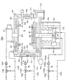
ここで,本実施の形態にかかる温度調節装置によって温度調節が行われるCVD処理部15a〜15cの構成について説明する。図2は,CVD処理部15aの構成の概略を示すための縦断面の説明図である。
Here, the structure of
例えばCVD処理部15aは,処理室Sを形成する略円筒状の処理容器としての筐体30を有している。筐体30内には,ウェハWを載置する載置台31が設けられている。載置台31内には,載置されたウェハWを昇温させるための第1のヒータ32が内蔵されている。載置台31は,ロッドステージ33に立設された縦長のロッド34の上に支持されている。ロッドステージ33は,筐体30の下部に設けられた昇降機構35に連動している。この昇降機構35により,ロッドステージ33が昇降し,載置台31は筐体30内で昇降できる。載置台31の熱が伝導する上記ロッドステージ33内には,例えば後述する冷凍機101から供給される冷媒を流通させる第1の冷媒流通部36と,ロッドステージ33の温度を検出する第1の温度センサ37が設けられている。
For example, the
筐体30内には,搬入出時にウェハWを支持する支持ピン40が設けられている。支持ピン40は,ウェハWを支持した後,載置台31が上昇することによって,載置台31にウェハWを渡すことができる。
Support pins 40 that support the wafer W during loading / unloading are provided in the
筐体30の天井部50には,マイクロ波発生装置51が設けられている。天井部50には,後述する冷凍機101からの冷媒を流通させる第2の冷媒流通部52と,天井部50の温度を検出する第2の温度センサ53が設けられている。第2の冷媒流通部52は,例えば天井部50の中央にあるマイクロ波供給管54を中心とした,平面から見て渦巻き状に配置された流路によって構成されている。
A
筐体30には,例えばプラズマを発生させるためのガスを処理室S内に導入するガス導入部60が設けられている。また,筐体30の側壁部61の内側面には,処理室S内を昇温するための第2のヒータ62が設けられている。筐体30の側壁部61内には,後述する冷凍機からの冷媒を流通させる第3の冷媒流通部63と,側壁部61の温度を検出する第3の温度センサ64が設けられている。第3の冷媒流通部63は,例えば環状の側壁部61内を蛇行しながら一周する流路によって構成されている。
The
例えば上述の各温度センサ37,53,64による検出結果は,例えばCVD処理部15aの各種諸元の動作を制御する制御部65に出力できる。
For example, the detection results obtained by the
筐体30の下部には,処理室S内の雰囲気を排気する排気部70が形成されている。筐体30の側壁部61には,ウェハWを搬入出するための搬入出口71が形成されている。
An
本実施の形態においてCVD処理部15b,15cの構成は,CVD処理部15aと同様であるので,その説明を省略する。
In this embodiment, the configuration of the
以上のように構成されたCVD処理部15a〜15cでは,第1及び第2のヒータ32,62により処理室S内と載置台31が所定の温度まで昇温された状態で,処理室S内にウェハWが搬入される。処理室S内に搬入されたウェハWは,支持ピン40に支持された後,載置台31上に載置される。その後,ガス導入部60から処理室S内に所定のガスが導入され,マイクロ波発生装置51によってそのガスにマイクロ波が付加される。そのマイクロ波の付加によって,処理室S内にプラズマが生成され,そのプラズマによってウェハW上に所定の膜が形成される。
In the
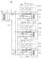
次に,上述のCVD処理部15a〜15cの温度制御を行う温度調節装置100について説明する。図3は,温度調節装置100の構成の概略を示す模式図である。
Next, the
温度調節装置100は,例えば一台の冷凍機101と,冷凍機101から各CVD処理部15a〜15cに冷媒を供給する往路である第1の流路102と,各CVD処理部15a〜15cから冷凍機101に冷媒を戻す還路である第2の流路103と,各CVD処理部15a〜15c毎に配置された循環路104a,104b,104cを有している。
The
第1の流路102の上流部には,各CVD処理部15a〜15cに冷媒を圧送するためのポンプPが設けられている。第1の流路102は,途中で分岐し,各CVD処理部15a〜15cの各循環路104a〜104cに接続されている。例えば第1の流路102と各循環路104a〜104cとの接続部には,三方弁105a,105b,105cがそれぞれ設けられている。これにより,第1の流路102,循環路104a〜104c及び第2の流路103を順に流通する冷媒の流れと,循環路104a〜104c内で冷媒が循環する流れとを切り換えることができる。また,冷媒が循環している状態の循環路104a内に第1の流路102から所定の流量の冷媒を流入させることができる。
A pump P for pumping the refrigerant to each of the
循環路104a〜104cは,図2及び図3に示すように各CVD処理部15a〜15cの所定の温度調節対象,例えばロッドステージ33を通るように配置されている。つまり,上述した各CVD処理部15a〜15cの第1の冷媒流通部36は,循環路104a〜104cの一部を構成している。各循環路104a〜104cには,各循環路104a〜104c内の冷媒の循環を促進させる循環用ポンプ106a,106b,106cが設けられている。
そして三方弁105aと循環用ポンプ106aの間,三方弁105bと循環用ポンプ106bとの間,及び三方弁105cと循環用ポンプ106cとの間には,例えば空気逃がし口やリリーフ弁などを備えたバッファタンクBが各々設けられている。これによって各循環用ポンプ106a,106b,106cの作動によって,循環路104a〜104c内において,圧力変動が生じた際に,これを吸収して安定した冷媒の流通を確保することができる。
As shown in FIGS. 2 and 3, the
For example, an air relief port or a relief valve is provided between the three-
第2の流路103は,図3に示すように各循環路104a〜104cに接続されており,各循環路104a〜104c内を通過した冷媒を冷凍機101に戻すことができる。
そして第1の流路102と第2の流路103との間には,各CVD処理部15a,15b,15cを迂回して,第1の流路102と第2の流路103とを連通させるバイパス管151が配管されている。バイパス管151には,バルブ152が設けられている。これによって,三方弁105a〜105cの切り替え等によって,各循環路104a〜104cが閉鎖された場合に,第1の流路102内の圧力が異常に上昇するのを防止することが可能である。したがって,バルブ152は一種のリリーフ弁として機能する。なおこのバルブ152の開閉制御は,前記三方弁105a〜105cと連動して制御してもよい。すなわち,例えば三方弁105a〜105cのいずれもが第1の流路102に対して閉鎖作動をした際に,このバルブ152を開放する制御を行ってもよい。
As shown in FIG. 3, the
And between the
上述した各CVD処理部15a〜15cの各制御部65は,各CVD処理部15a〜15cの第1の温度センサ37によって検出された温度に基づいて循環用ポンプ106a〜106cの動作を制御するポンプ動作制御部107a,107b,107cを備えている。これにより,ロッドステージ33の温度に基づいて循環用ポンプ106a〜106cの動作を制御して,循環路104a〜104c内の冷媒の流速を調整できる。また,制御部65は,第1の温度センサ37によって検出された温度に基づいて三方弁105a〜105cの動作を制御する弁制御部108a,108b,108cを備えている。これにより,ロッドステージ33の温度に基づいて,三方弁105a〜105cの開閉度を制御して,第1の流路102から各循環路104a〜104c内への冷媒の取り入れの有無や冷媒の取り入れ流量の調整を行うことができる。なお,冷凍機101には,例えば工場循環水が流通する管路109が設けられている。
Each
次に,以上のように構成された温度調節装置100の動作について説明する。冷凍機101が稼動し,ポンプPによって第1の流路102に冷媒が送られると,冷媒は,第1の流路102を通って各CVD処理部15a〜15cの各循環路104a〜104cに分割供給され,その後,各循環路104a〜104cから第2の流路103を通って冷凍機101に戻される。また,例えば各CVD処理部15a〜15cにおける三方弁105a〜105cによって,第1の流路102から循環路104a〜104cへの冷媒の流れが遮断され,循環用ポンプ106a〜106cが稼動すると,各循環路104a〜104c内において冷媒が循環する。
Next, the operation of the
また,三方弁105a〜105cの開閉度を調節して,第1の流路102から循環路104a〜104cへの冷媒の流れと循環路104a〜104c内の冷媒の流れの両方を維持すると,冷凍機101から供給される所定流量の冷媒が循環路104a〜104c内で循環している冷媒内に取り入れられる。そして,第1の流路102から流入した分量の冷媒が循環路104a〜104cから第2の流路103に流出し,第2の流路103を通って冷凍機101に戻される。
通常,三方弁は1の流路から弁本体に流れ込む流体を,別の2つの流路に振り分けて流すために使用されるが,前記図3に示した三方弁105a〜105cは,これを逆に用いたものであり,第1の流路102と循環路104a〜104cの出口側から三方弁105a〜105cに流れ込む流体を,循環路104a〜104cの入り口側に流すようにしている。すなわち2つの流路からの流体の混合割合を調整して,流体の循環路104a〜104cの入り口側に流すようにしているものである。
In addition, by adjusting the degree of opening and closing of the three-
Normally, the three-way valve is used to distribute the fluid flowing into the valve body from one flow path to another two flow paths, but the three-
例えば,各CVD処理部15a〜15cにおけるCVD処理中は,載置台31の温度が安定するように,ロッドステージ33の温度が所定の温度以上ならないように温度調節される。CVD処理中は,各CVD処理部15a〜15cにおいて,第1の温度センサ37により,ロッドステージ33の温度が常にモニタリングされている。
For example, during the CVD process in each of the
例えば冷凍機101から供給される冷媒の温度が−30℃で,CVD処理部15aのロッドステージ33の上限温度が−20℃に設定されている場合,ロッドステージ33の温度が−20℃以下の低い温度のときには,例えば三方弁105aにより第1の流路102から循環路104aへの冷媒の流入が遮断され,循環用ポンプ106aにより循環路104a内の冷媒が循環路104a内を所定の速度で循環する。このとき,循環路104a内では,冷媒が短い周期で循環するため,循環路104a内の冷媒の温度差が小さくなる。この結果,第1の冷媒流通部36の入口と出口における冷媒の温度差も小さくなり,ロッドステージ33の温度が斑なく維持される。また,このとき,冷凍機101からの冷媒の供給が停止され,循環路104a内の少ない冷媒量で温度調節されるので,冷凍機101等の消費電力を低減できる。
For example, when the temperature of the refrigerant supplied from the
例えばロッドステージ33の温度が−20℃を越えたときには,三方弁105aの開閉度が調整され,循環路104a内の冷媒の循環が維持されまま,第1の流路102から循環路104a内に−30℃の低温の冷媒が取り入れられる。これにより,循環路104a内で循環する冷媒の温度が低下し,ロッドステージ33の温度が下げられる。
For example, when the temperature of the
CVD処理部15b,15cにおいても,CVD処理部15aと同様に,第1の温度センサ37によって検出されたロッドステージ33の温度に基づいて,循環路105b,105cのおける冷媒の循環と,第1の流路102から循環路105b,105c内への新しい冷媒の取り入れとを切り換えることによって,各CVD処理部15b,15cで各々定められた温度以下にロッドステージ33の温度を維持することができる。
Also in the
以上の実施の形態によれば,一台の冷凍機101と複数のCVD処理部15a〜15cを接続する第1の流路102が配置され,冷凍機101から複数のCVD処理部15a〜15cに冷媒を分割供給できるようにしたので,従来に比べて配管の総数を減らすことができ,配管の設置スペースやコストを低減できる。また,冷凍機101の設置スペースも少なく抑えることができる。各CVD処理部15a〜15cに配置された短い循環路104a〜104cで冷媒を循環させ,循環路104a〜104c内の冷媒の温度差を抑制したので,各CVD処理部15a〜15cにおけるロッドステージ33を斑なく安定的に温度調節することができる。
According to the above embodiment, the
第1の流路102と各循環路104a〜104cの接続部に三方弁105a〜105cが設けられたので,第1の流路102内の新しい冷媒を必要に応じて循環路104a〜104c内に取り入れることができる。これにより,例えばロッドステージ33の温度が上昇した場合に,冷凍機101からの低温の冷媒が循環路104a〜104c内で循環している冷媒内に混合され,循環路104a〜104c内の冷媒温度を低下させることができる。この結果,ロッドステージ33の温度を迅速に下げることができる。また,三方弁105a〜105cの動作制御が,第1の温度センサ37による温度の検出結果に基づいて行われたので,温度調節を正確かつ迅速に行うことができる。
Since the three-
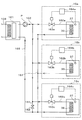
以上の実施の形態における各CVD処理部15a〜15cの各循環路104a〜104cに,図4に示すように加熱部材としてのヒータ120a,120b,120cが設けられてもよい。この場合,各制御部65には,第1の温度センサ37によって検出された温度に基づいてヒータ120a〜120cによる加熱を制御する加熱制御部121a,121b,121cが設けられる。かかる場合,例えばCVD処理部15a〜15cの例えばロッドステージ33の温度が目標温度よりも下がったとき,加熱制御部121a〜121cによってヒータ120a〜120cを作動させ,循環路104a〜104c内の冷媒を昇温させる。こうすることによって,ロッドステージ33の温度を積極的に上昇させることができ,例えばロッドステージ33を所望の目標温度に調節することができる。
As shown in FIG. 4,
以上の実施の形態では,載置台31の温度を安定させるために,ロッドステージ33の温度を調節していたが,載置台31内に循環路104a〜104cを通して載置台31を直接温度調節してもよい。
In the above embodiment, the temperature of the
また,以上の実施の形態では,CVD処理部15a〜15cのロッドステージ33を温度調節の対象にしていたが,CVD処理部15a〜15cにおける他の部分,例えば筐体30の天井部50,側壁部61を温度調節の対象にしてもよい。この場合,各CVD処理部15a〜15cにおいて,例えば図5に示すように第2の冷媒流通部52を通る循環路130と,第3の冷媒流通部63を通る循環路131が形成され,その循環路130,131が第1の流路102と第2の流路103に接続される。循環路130,131には,それぞれ三方弁132,133と循環用ポンプ134,135が設けられる。そして,上述したロッドステージ33の温度調節と同様に,第2の温度センサ53と第3の温度センサ64によって検出された温度に基づいて,三方弁132,133と循環用ポンプ134,135の動作が制御され,天井部50と側壁部61の温度が調整される。
Further, in the above embodiment, the
以上の実施の形態で使用された三方弁は,通常の三方弁をいわば逆に用いて,2つの流路からの流体の混合割合を調整して,他の流路に流体を流すように使用していたが,もちろん本来の使用法のように,1つの流路から流れ込んでくる流体を別の2つの流路に振り分けるように使用してもよい。図6は,かかる例を図3のCVD処理部15aに即して示してものであり,この例では,三方弁105aは,循環路104aからの流体が,第2の流路103側と,第1の流路1025との合流側へと分岐する三叉部に使用されている。かかるようにして三方弁を使用しても,もちろん既述した例と同一の作用効果が得られる。
The three-way valve used in the above embodiment is used to adjust the mixing ratio of the fluid from the two flow paths and flow the fluid to the other flow paths by using the normal three-way valve in reverse. However, as a matter of course, it may be used so that the fluid flowing from one flow path is distributed to two other flow paths as in the original usage. FIG. 6 shows such an example in conformity with the
上記した実施の形態においては,いずれも各処理部に循環路を配管して,三方弁による流体の振り分けや流量調整によって,CVD処理部の温度調節対象の温度を調節するようにしていたが,配管をさらに簡素化し,三方弁に代えて通常の二方弁を使用することもできる。 In each of the above-described embodiments, a circulation path is connected to each processing unit, and the temperature of the temperature control target of the CVD processing unit is adjusted by distributing the fluid and adjusting the flow rate by a three-way valve. The piping can be further simplified, and a normal two-way valve can be used instead of the three-way valve.
図7はかかる例を示しており,この例では,例えばCVD処理部15aについていうと,第1の流路102から取り入れた冷媒が,冷媒流通部36を巡って,そのまま第2の流路103に通ずる帰還路161へと流れ込むような巡回路162aが配管されている。そしてこの巡回路162aには弁163aが設けられており,この弁163aの開閉制御によって冷媒流通部36に流れ込む冷媒の流量を調節することが可能になっている。弁163aの制御は,温度センサ37からの測定信号に基づいて制御装置164aによって制御される。他のCVD処理部15b,15cにおける,巡回路162b,162c,弁163b,163c,制御装置164b,164cについても全く同様な構成である。
FIG. 7 shows such an example. In this example, for example, regarding the
またCVD処理部15aについていえば,図8に模式的に示したように,温度調節対象部位,たとえばロッドステージ33の温度制御は,既述した冷媒流通部36に流れる冷媒,たとえばチラーや水による冷却と,ヒータ171による加熱の双方によってなされる。ヒータ171の温度調節自体は電源172を制御することによってなされる。
As for the
したがって,この例では,温度センサ37の測定信号によって,所定の上限温度,例えば−10℃を超えた高い温度になったら,弁163aを開放して,循環路162aから冷媒流通部36に対して,冷媒を流通させる制御が行われる。またヒータ171についても同様に,所定の設定温度,例えば−20℃より低い温度になったら,電源172を操作して,ヒータ171を作動させて加熱する。かかる制御も制御装置164aによってなされる。他のCVD処理部15b,15cについても同様な構成である。
Therefore, in this example, when a high temperature exceeding a predetermined upper limit temperature, for example, −10 ° C., is reached by the measurement signal of the
このような巡回路162a〜162cと弁163a〜163cによる温度調節は,温度調節対象が比較的ラフな温度調節で足りる場合に有効であり,しかも既述した循環路と三方弁の組み合わせの例よりも,配管周りが簡素化され,しかも循環用ポンプなどが不要になるというメリットがある。
Such temperature control by the
以上,本発明の実施の形態の一例について説明したが,本発明はこの例に限らず種々の態様を採りうるものである。例えば,本実施の形態では,温度調節装置100によって,3台のCVD処理部が温度調節されていたが,その数は,任意に選択できる。温度調節される基板処理部は,CVD処理部15a〜15cに限られず,例えば温度制御の必要な,CVD以外の膜形成処理部,エッチング処理部及び熱処理部等の他の基板処理部であってもよい。また,温度調節される基板処理部は,同じ基板処理システム1内の基板処理部に限られず,複数の基板処理システムに渡る基板処理部であってもよい。本実施の形態で記載したウェハWは,例えばFPD(フラットパネルディスプレイ)基板,マスク基板,レクチル基板などの他の基板であってもよい。
The example of the embodiment of the present invention has been described above, but the present invention is not limited to this example and can take various forms. For example, in the present embodiment, the temperature of the three CVD processing units is adjusted by the
本発明は,工場内の複数の基板処理部の温度制御を,省スペース,省コストで実現する際に有用である。 The present invention is useful for realizing temperature control of a plurality of substrate processing units in a factory with space saving and cost saving.
1 基板処理システム
15a〜15c CVD処理部
33 ロッドステージ
100 温度調節装置
101 冷凍機
102 第1の流路
103 第2の流路
104a〜104c 循環路
105a〜105c 三方弁
106a〜106c 循環用ポンプ
W ウェハ
DESCRIPTION OF
Claims (13)
前記往路及び還路を閉鎖し,前記循環路内にある冷媒の循環によって,前記温度調節対象の温度を調節することを特徴とする,請求項2に記載の温度調節方法。 The circulation path is connected to an outward path for supplying the refrigerant from the refrigerator and a return path to return to the refrigerator.
3. The temperature adjustment method according to claim 2, wherein the forward path and the return path are closed, and the temperature of the temperature adjustment target is adjusted by circulation of a refrigerant in the circulation path.
1台の冷凍機と,
前記冷凍機から前記各基板処理部に冷媒を供給するための第1の流路と,
前記各基板処理部から前記冷凍機に冷媒を戻すための第2の流路と,
前記各基板処理部の温度調節対象内を通り,冷媒を循環させる循環路と,を備え,
前記循環路には,前記第1の流路と前記第2の流路が接続されており,
前記第1の流路から前記循環路に流入する冷媒の流量を調節する弁をさらに備えたことを特徴とする,温度調節装置。 A temperature adjustment device for adjusting the temperature of each temperature adjustment target of a plurality of substrate processing units,
One refrigerator,
A first flow path for supplying a refrigerant from the refrigerator to each substrate processing unit;
A second flow path for returning the refrigerant from each of the substrate processing units to the refrigerator;
A circulation path that circulates the refrigerant through the temperature control target of each substrate processing unit,
The circulation path is connected to the first flow path and the second flow path,
The temperature control apparatus further comprising a valve for adjusting a flow rate of the refrigerant flowing from the first flow path into the circulation path.
前記温度センサによって検出された温度に基づいて前記弁の動作を制御する弁制御部と,をさらに備えたことを特徴とする,請求項6又は7のいずれかに記載の温度調節装置。 A temperature sensor for detecting a temperature of the temperature adjustment target;
The temperature control device according to claim 6, further comprising: a valve control unit that controls the operation of the valve based on the temperature detected by the temperature sensor.
前記温度センサによって検出された温度に基づいて前記加熱部材による加熱を制御する加熱制御部と,をさらに備えたことを特徴とする,請求項8に記載の温度調節装置。 A heating member for heating the refrigerant circulating in the circulation path;
The temperature control apparatus according to claim 8, further comprising a heating control unit that controls heating by the heating member based on a temperature detected by the temperature sensor.
Priority Applications (3)
| Application Number | Priority Date | Filing Date | Title |
|---|---|---|---|
| JP2004344150A JP2005210080A (en) | 2003-12-25 | 2004-11-29 | Temperature-control method and temperature-control device |
| PCT/JP2004/019406 WO2005064659A1 (en) | 2003-12-25 | 2004-12-24 | Temperature regulating method for substrate treating system and substrate treating system |
| US10/583,847 US20080271471A1 (en) | 2003-12-25 | 2004-12-24 | Temperature Controlling Method for Substrate Processing System and Substrate Processing System |
Applications Claiming Priority (2)
| Application Number | Priority Date | Filing Date | Title |
|---|---|---|---|
| JP2003430954 | 2003-12-25 | ||
| JP2004344150A JP2005210080A (en) | 2003-12-25 | 2004-11-29 | Temperature-control method and temperature-control device |
Publications (2)
| Publication Number | Publication Date |
|---|---|
| JP2005210080A true JP2005210080A (en) | 2005-08-04 |
| JP2005210080A5 JP2005210080A5 (en) | 2008-01-17 |
Family
ID=34742121
Family Applications (1)
| Application Number | Title | Priority Date | Filing Date |
|---|---|---|---|
| JP2004344150A Pending JP2005210080A (en) | 2003-12-25 | 2004-11-29 | Temperature-control method and temperature-control device |
Country Status (3)
| Country | Link |
|---|---|
| US (1) | US20080271471A1 (en) |
| JP (1) | JP2005210080A (en) |
| WO (1) | WO2005064659A1 (en) |
Cited By (10)
| Publication number | Priority date | Publication date | Assignee | Title |
|---|---|---|---|---|
| JP2009168403A (en) * | 2008-01-18 | 2009-07-30 | Nishiyama Corp | Chiller device |
| JP2009287865A (en) * | 2008-05-30 | 2009-12-10 | Yurikai Co Ltd | Multiple load temperature control device in plant |
| JP2013167458A (en) * | 2012-02-14 | 2013-08-29 | Seiko Epson Corp | Handler and component inspection apparatus |
| JP2015079930A (en) * | 2013-10-17 | 2015-04-23 | テキスト カンパニー リミテッド | Temperature control system for semiconductor manufacturing facility |
| JP5938506B1 (en) * | 2015-09-17 | 2016-06-22 | 株式会社日立国際電気 | Substrate processing system, semiconductor device manufacturing method, program, and recording medium |
| JP2017135316A (en) * | 2016-01-29 | 2017-08-03 | 株式会社日立国際電気 | Substrate processing device, method of manufacturing semiconductor device, program, and recording medium |
| KR101940287B1 (en) * | 2018-02-08 | 2019-01-18 | (주)테키스트 | Temperature regulation device for manufacturing semiconductor |
| WO2021002228A1 (en) * | 2019-07-01 | 2021-01-07 | 株式会社Kokusai Electric | Substrate processing device, manufacturing method for semiconductor device, and program |
| JP2021132101A (en) * | 2020-02-19 | 2021-09-09 | 東京エレクトロン株式会社 | Substrate processing device and substrate processing method |
| KR102339630B1 (en) * | 2021-02-16 | 2021-12-23 | ㈜엑스포 | Chiller for semiconductor process device |
Families Citing this family (16)
| Publication number | Priority date | Publication date | Assignee | Title |
|---|---|---|---|---|
| JP4564973B2 (en) * | 2007-01-26 | 2010-10-20 | 株式会社日立ハイテクノロジーズ | Plasma processing equipment |
| JP5032269B2 (en) * | 2007-11-02 | 2012-09-26 | 東京エレクトロン株式会社 | Temperature adjusting apparatus and temperature adjusting method for substrate to be processed, and plasma processing apparatus including the same |
| WO2010039773A1 (en) * | 2008-09-30 | 2010-04-08 | Vette Corp. | Free-cooling including modular coolant distribution unit |
| JP5570938B2 (en) * | 2009-12-11 | 2014-08-13 | 株式会社日立国際電気 | Substrate processing apparatus and semiconductor device manufacturing method |
| KR101108337B1 (en) * | 2009-12-31 | 2012-01-25 | 주식회사 디엠에스 | Apparatus for controlling temperature of electrostatic chuck comprising internal 2 stage refrigrants route |
| US9338871B2 (en) * | 2010-01-29 | 2016-05-10 | Applied Materials, Inc. | Feedforward temperature control for plasma processing apparatus |
| US8916793B2 (en) | 2010-06-08 | 2014-12-23 | Applied Materials, Inc. | Temperature control in plasma processing apparatus using pulsed heat transfer fluid flow |
| US20110269314A1 (en) * | 2010-04-30 | 2011-11-03 | Applied Materials, Inc. | Process chambers having shared resources and methods of use thereof |
| US8880227B2 (en) * | 2010-05-27 | 2014-11-04 | Applied Materials, Inc. | Component temperature control by coolant flow control and heater duty cycle control |
| JP5750304B2 (en) * | 2011-05-18 | 2015-07-22 | 株式会社日立製作所 | Electronic equipment cooling system |
| US10274270B2 (en) | 2011-10-27 | 2019-04-30 | Applied Materials, Inc. | Dual zone common catch heat exchanger/chiller |
| US9957601B2 (en) * | 2013-03-15 | 2018-05-01 | Applied Materials, Inc. | Apparatus for gas injection in a physical vapor deposition chamber |
| CN105247288B (en) * | 2013-05-31 | 2018-01-30 | 三菱电机株式会社 | Thermal medium converting means and the air-conditioning device for possessing the thermal medium converting means |
| JP5841281B1 (en) * | 2015-06-15 | 2016-01-13 | 伸和コントロールズ株式会社 | Chiller device for plasma processing equipment |
| US10662529B2 (en) * | 2016-01-05 | 2020-05-26 | Applied Materials, Inc. | Cooled gas feed block with baffle and nozzle for HDP-CVD |
| SG11202005615TA (en) | 2017-12-20 | 2020-07-29 | Technetics Group Llc | Deposition processing systems having active temperature control and associated methods |
Citations (3)
| Publication number | Priority date | Publication date | Assignee | Title |
|---|---|---|---|---|
| JPH05163096A (en) * | 1991-12-11 | 1993-06-29 | Applied Materials Japan Kk | Temperature control system for low-temperature of electrode in vacuum device using refrigerator in apparatus for producing semiconductor |
| JPH11183005A (en) * | 1997-12-24 | 1999-07-06 | Innotech Corp | Chiller |
| JP2000284832A (en) * | 1999-03-31 | 2000-10-13 | Komatsu Ltd | Temperature controller and valve control part of the same |
Family Cites Families (3)
| Publication number | Priority date | Publication date | Assignee | Title |
|---|---|---|---|---|
| JPH0529261A (en) * | 1991-07-19 | 1993-02-05 | Hitachi Ltd | Stage temperature control device |
| FR2716959B1 (en) * | 1994-03-04 | 1996-05-15 | Thermique Generale Vinicole | Distribution and / or collection of cold and / or hot. |
| US6062485A (en) * | 1998-04-22 | 2000-05-16 | Erie Manufacturing Company | Radiant heating system reset control |
-
2004
- 2004-11-29 JP JP2004344150A patent/JP2005210080A/en active Pending
- 2004-12-24 US US10/583,847 patent/US20080271471A1/en not_active Abandoned
- 2004-12-24 WO PCT/JP2004/019406 patent/WO2005064659A1/en active Application Filing
Patent Citations (3)
| Publication number | Priority date | Publication date | Assignee | Title |
|---|---|---|---|---|
| JPH05163096A (en) * | 1991-12-11 | 1993-06-29 | Applied Materials Japan Kk | Temperature control system for low-temperature of electrode in vacuum device using refrigerator in apparatus for producing semiconductor |
| JPH11183005A (en) * | 1997-12-24 | 1999-07-06 | Innotech Corp | Chiller |
| JP2000284832A (en) * | 1999-03-31 | 2000-10-13 | Komatsu Ltd | Temperature controller and valve control part of the same |
Cited By (17)
| Publication number | Priority date | Publication date | Assignee | Title |
|---|---|---|---|---|
| JP2009168403A (en) * | 2008-01-18 | 2009-07-30 | Nishiyama Corp | Chiller device |
| JP2009287865A (en) * | 2008-05-30 | 2009-12-10 | Yurikai Co Ltd | Multiple load temperature control device in plant |
| JP2013167458A (en) * | 2012-02-14 | 2013-08-29 | Seiko Epson Corp | Handler and component inspection apparatus |
| JP2015079930A (en) * | 2013-10-17 | 2015-04-23 | テキスト カンパニー リミテッド | Temperature control system for semiconductor manufacturing facility |
| JP5938506B1 (en) * | 2015-09-17 | 2016-06-22 | 株式会社日立国際電気 | Substrate processing system, semiconductor device manufacturing method, program, and recording medium |
| JP2017059714A (en) * | 2015-09-17 | 2017-03-23 | 株式会社日立国際電気 | Substrate processing system, method of manufacturing semiconductor device, program, and storage medium |
| US9818630B2 (en) | 2016-01-29 | 2017-11-14 | Hitachi Kokusai Electric Inc. | Substrate processing apparatus |
| CN107026101A (en) * | 2016-01-29 | 2017-08-08 | 株式会社日立国际电气 | The manufacture method of lining processor, semiconductor devices |
| JP2017135316A (en) * | 2016-01-29 | 2017-08-03 | 株式会社日立国際電気 | Substrate processing device, method of manufacturing semiconductor device, program, and recording medium |
| KR101940287B1 (en) * | 2018-02-08 | 2019-01-18 | (주)테키스트 | Temperature regulation device for manufacturing semiconductor |
| WO2021002228A1 (en) * | 2019-07-01 | 2021-01-07 | 株式会社Kokusai Electric | Substrate processing device, manufacturing method for semiconductor device, and program |
| JP2021132101A (en) * | 2020-02-19 | 2021-09-09 | 東京エレクトロン株式会社 | Substrate processing device and substrate processing method |
| JP7277400B2 (en) | 2020-02-19 | 2023-05-18 | 東京エレクトロン株式会社 | SUBSTRATE PROCESSING APPARATUS AND SUBSTRATE PROCESSING METHOD |
| US11817334B2 (en) | 2020-02-19 | 2023-11-14 | Tokyo Electron Limited | Substrate processing apparatus and substrate processing method |
| TWI824232B (en) * | 2020-02-19 | 2023-12-01 | 日商東京威力科創股份有限公司 | Substrate processing apparatus and substrate processing method |
| JP7450087B2 (en) | 2020-02-19 | 2024-03-14 | 東京エレクトロン株式会社 | Temperature control system and substrate processing system |
| KR102339630B1 (en) * | 2021-02-16 | 2021-12-23 | ㈜엑스포 | Chiller for semiconductor process device |
Also Published As
| Publication number | Publication date |
|---|---|
| WO2005064659A1 (en) | 2005-07-14 |
| US20080271471A1 (en) | 2008-11-06 |
Similar Documents
| Publication | Publication Date | Title |
|---|---|---|
| JP2005210080A (en) | Temperature-control method and temperature-control device | |
| KR100836607B1 (en) | Apparatus and method for processing substrate, and apparatus and method for supplying energy consumed therin | |
| US7216496B2 (en) | Heating medium circulating device and thermal, treatment equipment using the device | |
| KR101109730B1 (en) | Chiller apparatus for semiconductor process and Method for controlling temperature in the same | |
| KR101975007B1 (en) | cooling system for semiconductor parts cooling | |
| US8110044B2 (en) | Substrate processing apparatus and temperature control device | |
| US6569696B2 (en) | Device and method for manufacturing semiconductor | |
| KR19980081166A (en) | Temperature control system for semiconductor processing equipment | |
| JP7450087B2 (en) | Temperature control system and substrate processing system | |
| US20090126378A1 (en) | Chiller of etch equipment for semiconductor processing | |
| KR102469166B1 (en) | Substrate processing system and method for supplying processing fluid | |
| KR102134949B1 (en) | Processing liquid supplying apparatus, substrate processing apparatus and processing liquid supplying method | |
| US6349546B1 (en) | Liquid gas exchanger | |
| KR20110125595A (en) | Temperature controller, fluid circulator, and temperature control method using temperature controller | |
| TWI815346B (en) | Substrate processing device, semiconductor device manufacturing method and program | |
| KR20130031945A (en) | Apparatus for controlling temperature of loading chuck and method of controlling temperature | |
| KR20210020523A (en) | temperature-adjusting device for high temperature having an open or close adjusting valve system | |
| KR100404651B1 (en) | Chiller of Semiconductor Manufacturing Equipment | |
| JP2005197471A (en) | Substrate processing equipment and temperature control method | |
| KR20190078791A (en) | Semiconductor cooling system for improving the temperature deviation of semiconductor test | |
| KR20020066358A (en) | Multi-channel temperature control system for semiconductor processing facilities | |
| JP3851444B2 (en) | Heat treatment equipment | |
| KR100653455B1 (en) | Chiller for semiconductor progress having high temperature type and low temperature type heater exchanger | |
| US20230017834A1 (en) | Subfab area installation apparatus | |
| JP2000124184A (en) | Cooling water thermostatic device for chemical |
Legal Events
| Date | Code | Title | Description |
|---|---|---|---|
| A521 | Written amendment |
Free format text: JAPANESE INTERMEDIATE CODE: A523 Effective date: 20071121 |
|
| A621 | Written request for application examination |
Free format text: JAPANESE INTERMEDIATE CODE: A621 Effective date: 20071121 |
|
| A131 | Notification of reasons for refusal |
Free format text: JAPANESE INTERMEDIATE CODE: A131 Effective date: 20100928 |
|
| A02 | Decision of refusal |
Free format text: JAPANESE INTERMEDIATE CODE: A02 Effective date: 20110419 |