JP2005207367A - Hybrid automobile - Google Patents
Hybrid automobile Download PDFInfo
- Publication number
- JP2005207367A JP2005207367A JP2004017025A JP2004017025A JP2005207367A JP 2005207367 A JP2005207367 A JP 2005207367A JP 2004017025 A JP2004017025 A JP 2004017025A JP 2004017025 A JP2004017025 A JP 2004017025A JP 2005207367 A JP2005207367 A JP 2005207367A
- Authority
- JP
- Japan
- Prior art keywords
- internal combustion
- combustion engine
- power
- ventilation
- output
- Prior art date
- Legal status (The legal status is an assumption and is not a legal conclusion. Google has not performed a legal analysis and makes no representation as to the accuracy of the status listed.)
- Pending
Links
Images


Classifications
-
- Y—GENERAL TAGGING OF NEW TECHNOLOGICAL DEVELOPMENTS; GENERAL TAGGING OF CROSS-SECTIONAL TECHNOLOGIES SPANNING OVER SEVERAL SECTIONS OF THE IPC; TECHNICAL SUBJECTS COVERED BY FORMER USPC CROSS-REFERENCE ART COLLECTIONS [XRACs] AND DIGESTS
- Y02—TECHNOLOGIES OR APPLICATIONS FOR MITIGATION OR ADAPTATION AGAINST CLIMATE CHANGE
- Y02T—CLIMATE CHANGE MITIGATION TECHNOLOGIES RELATED TO TRANSPORTATION
- Y02T10/00—Road transport of goods or passengers
- Y02T10/60—Other road transportation technologies with climate change mitigation effect
- Y02T10/62—Hybrid vehicles
Abstract
Description
本発明は、ハイブリッド自動車に関し、詳しくは、内燃機関と電動機とを備え、該内燃機関からのエネルギの少なくとも一部を用いて該電動機からの動力により走行可能なハイブリッド自動車に関する。 The present invention relates to a hybrid vehicle, and more particularly, to a hybrid vehicle that includes an internal combustion engine and an electric motor and that can travel by power from the electric motor using at least a part of energy from the internal combustion engine.
従来、この種の自動車としては、エンジンのピストンとシリンダとの隙間からクランクケース内に抜ける未燃焼のガス(ブローバイガス)を吸気系に還元してクランクケース内を換気するシステムを備えるものが提案されている(例えば、特許文献1参照)。このシステムでは、エンジンの吸気系の負圧を利用してクランクケース内のブローバイガスを吸気系に吸引させて再燃焼させると共にエアをクランクケース内に導入してクランクケース内を換気している。
しかしながら、こうしたシステムでは、エンジンのみを搭載する通常の自動車であれば十分に機能させることができるものの、エンジンとモータとを備えるハイブリッド自動車では、十分に機能させることができない場合が生じる。これは、ハイブリッド自動車では、エンジン効率の悪い低負荷の運転領域ではエンジンを停止させてモータのみを運転して走行することができるから、エンジンは常に効率の高い高負荷の領域で運転される状態となり、吸気系の負圧が十分に上昇しないことに基づいている。 However, in such a system, a normal vehicle equipped with only an engine can function sufficiently, but a hybrid vehicle including an engine and a motor may not function sufficiently. This is because, in a hybrid vehicle, the engine can be operated by driving only the motor while the engine is stopped in a low load operation region where the engine efficiency is low. Therefore, the engine is always operated in a high load region where the efficiency is high. This is based on the fact that the negative pressure of the intake system does not rise sufficiently.
本発明のハイブリッド自動車は、こうした問題を解決し、ハイブリッド自動車に搭載される内燃機関の内部の換気を十分に行なうことのできるようにすることを目的の一つとする。また、本発明のハイブリッド自動車は、ハイブリッド自動車に搭載される内燃機関の内部の換気を換気システムを変更することなく内燃機関と電動機の制御により実行することを目的の一つとする。さらに、本発明のハイブリッド自動車は、より適切なタイミングで内燃機関の内部の換気を行なうことを目的の一つとする。 One object of the hybrid vehicle of the present invention is to solve these problems and to sufficiently ventilate the internal combustion engine mounted in the hybrid vehicle. Another object of the hybrid vehicle of the present invention is to execute internal ventilation of the internal combustion engine mounted on the hybrid vehicle by controlling the internal combustion engine and the electric motor without changing the ventilation system. Another object of the hybrid vehicle of the present invention is to ventilate the internal combustion engine at a more appropriate timing.
本発明のハイブリッド自動車は、上述の目的の少なくとも一部を達成するために以下の手段を採った。 The hybrid vehicle of the present invention employs the following means in order to achieve at least a part of the above object.
本発明の第1のハイブリッド自動車は、
内燃機関と電動機とを備え、該内燃機関からのエネルギの少なくとも一部を用いて該電動機からの動力により走行可能なハイブリッド自動車であって、
前記内燃機関の吸気系の負圧を利用して該内燃機関の内部を換気する換気手段と、
前記内燃機関の内部に含まれるブローバイガスの含有量を検出または推定するブローバイガス含有量検出推定手段と、
前記検出または推定されたブローバイガスの含有量に基づいて前記内燃機関の内部の換気の要否を判定する換気要否判定手段と、
前記換気要否判定手段により前記内燃機関の内部の換気が不要と判定されたときには自動車に要求される要求動力が出力されるよう前記内燃機関と前記電動機とを制御する通常時運転制御を行ない、前記換気要否判定手段により前記内燃機関の内部の換気が必要と判定されたときには前記要求動力が出力されると共に前記換気手段による換気が促進されるよう前記内燃機関と前記電動機とを制御する換気時運転制御を行なう制御手段と、
を備えることを要旨とする。
The first hybrid vehicle of the present invention is
A hybrid vehicle comprising an internal combustion engine and an electric motor, and capable of traveling by power from the electric motor using at least a part of energy from the internal combustion engine,
Ventilation means for ventilating the interior of the internal combustion engine using the negative pressure of the intake system of the internal combustion engine;
Blowby gas content detection estimation means for detecting or estimating the content of blowby gas contained in the internal combustion engine;
Ventilation necessity determination means for determining necessity of ventilation inside the internal combustion engine based on the detected or estimated blowby gas content;
When the ventilation necessity determination means determines that ventilation inside the internal combustion engine is unnecessary, normal operation control is performed to control the internal combustion engine and the electric motor so that the required power required for the automobile is output, Ventilation for controlling the internal combustion engine and the electric motor so that the required power is output and the ventilation by the ventilation means is promoted when the ventilation necessity determination means determines that the internal ventilation of the internal combustion engine is necessary. Control means for performing hourly operation control;
It is a summary to provide.
この本発明の第1のハイブリッド自動車では、内燃機関の内部に含まれるブローバイガスの含有量を検出または推定し、検出または推定したブローバイガスの含有量に基づいて内燃機関の内部の換気の要否を判定し、内燃機関の内部の換気が不要と判定されたときには自動車に要求される要求動力が出力されるよう内燃機関と電動機とを制御する通常時運転制御を行ない、内燃機関の内部の換気が必要と判定されたときには要求動力が出力されると共に内燃機関の内部の換気が促進されるよう内燃機関と電動機とを制御する換気時運転制御を行なう。したがって、内燃機関の内部の換気をより適切なタイミングで実施することができる。もとより、要求動力に対処することができる。 In the first hybrid vehicle of the present invention, the content of blow-by gas contained in the internal combustion engine is detected or estimated, and the necessity of ventilation inside the internal combustion engine is determined based on the detected or estimated blow-by gas content. When the internal ventilation of the internal combustion engine is determined to be unnecessary, normal operation control is performed to control the internal combustion engine and the electric motor so that the required power required by the automobile is output. When it is determined that the engine is required, the engine is controlled during ventilation to control the internal combustion engine and the electric motor so that the required power is output and ventilation of the internal combustion engine is promoted. Therefore, the internal ventilation of the internal combustion engine can be performed at a more appropriate timing. Of course, it is possible to cope with the required power.
こうした本発明の第1のハイブリッド自動車において、前記ブローバイガス含有量検出推定手段は、前記内燃機関の運転状態に基づいて前記ブローバイガスの含有量を推定する手段であるものとすることもできる。こうすれば、ブローバイガスの含有量を直接検出するセンサを用いる必要がない。この態様の本発明の第1のハイブリッド自動車において、前記ブローバイガス含有量検出推定手段は、前記内燃機関の運転状態として、回転数,吸入負荷,運転時間の少なくとも一つに基づいて前記ブローバイガスの含有量を推定する手段であるものとすることもできる。さらに、この態様の本発明の第1のハイブリッド自動車において、前記ブローバイガス含有量検出推定手段は、前記内燃機関の回転数と負荷とに基づいて単位時間当たりのブローバイガスの変化量を推定し、該推定した変化量の積算値をもって前記ブローバイガスの含有量を推定する手段であるものとすることもできる。こうすれば、ブローバイガスの含有量をより正確に推定することができる。 In the first hybrid vehicle of the present invention, the blow-by gas content detection estimation means may be a means for estimating the blow-by gas content based on the operating state of the internal combustion engine. In this way, it is not necessary to use a sensor that directly detects the content of blowby gas. In the first hybrid vehicle of the present invention according to this aspect, the blow-by gas content detection estimation means is configured to determine the blow-by gas content based on at least one of a rotational speed, a suction load, and an operation time as an operation state of the internal combustion engine. It may be a means for estimating the content. Furthermore, in the first hybrid vehicle of the present invention of this aspect, the blow-by gas content detection estimating means estimates the amount of change in blow-by gas per unit time based on the rotational speed and load of the internal combustion engine, It can also be a means for estimating the content of the blow-by gas with the integrated value of the estimated amount of change. If it carries out like this, content of blowby gas can be estimated more correctly.
また、本発明の第1のハイブリッド自動車において、前記ブローバイガス含有量検出推定手段は、前記内燃機関に取り付けられ、ブローバイガスに含まれるNOxの量を検出するNOx検出手段であるものとすることもできる。こうすれば、より正確にブローバイガスの含有量を検出することができる。 In the first hybrid vehicle of the present invention, the blow-by gas content detection estimation unit may be a NOx detection unit that is attached to the internal combustion engine and detects the amount of NOx contained in the blow-by gas. it can. In this way, the blowby gas content can be detected more accurately.
さらに、本発明の第1のハイブリッド自動車において、前記換気要否判定手段は、前記検出または推定されたブローバイガスの含有量が第1所定量を超えたときに前記内燃機関の内部の換気が必要と判定する手段であるものとすることもできる。この態様の本発明の第1のハイブリッド自動車において、前記制御手段は、前記検出または推定されるブローバイガスの含有量が前記第1所定量よりも少ない第2所定量となるまで前記換気時運転制御を行なう手段であるものとすることもできるし、前記制御手段は、所定時間に亘って前記換気時運転制御を行なう手段であるものとすることもできる。こうすれば、内燃機関の内部の換気を十分に行なうことができる。 Further, in the first hybrid vehicle of the present invention, the ventilation necessity determination means needs to ventilate the internal combustion engine when the detected or estimated blowby gas content exceeds a first predetermined amount. It can also be a means for determining. In the first hybrid vehicle of the present invention according to this aspect, the control means controls the ventilation operation until the detected or estimated blowby gas content becomes a second predetermined amount smaller than the first predetermined amount. The control means may be a means for performing the ventilation operation control over a predetermined time. If it carries out like this, ventilation inside an internal combustion engine can fully be performed.
あるいは、本発明の第1のハイブリッド自動車において、前記内燃機関に所定の条件を課した際における該内燃機関のパワーと回転数およびトルクからなる運転ポイントとの関係としての第1の動作線と該第1の動作線よりも低トルクを出力する第2の動作線とを含む複数の動作線を記憶する動作線記憶手段を備え、前記制御手段は、前記要求動力に基づいて前記内燃機関から出力すべき目標パワーを設定し、前記換気要否判定手段により前記内燃機関の内部の換気が不要と判定されたときには前記設定した目標パワーと前記動作線記憶手段に記憶された前記第1の動作線とに基づいて前記内燃機関の運転ポイントを設定して該設定した運転ポイントで前記内燃機関が運転されると共に前記要求動力が出力されるよう前記内燃機関と前記電動機とを制御し、前記換気要否判定手段により前記内燃機関の内部の換気が必要と判定されたときには前記設定した目標パワーと前記動作線記憶手段に記憶された前記第2の動作線とに基づいて前記内燃機関の運転ポイントを設定して該設定した運転ポイントで前記内燃機関が運転されると共に前記要求動力が出力されるよう前記内燃機関と前記電動機とを制御する手段であるものとすることもできる。こうすれば、動作線を選択することにより、内燃機関を所定の条件で運転したり内燃機関の内部の換気を促進させる条件で運転したりすることができる。 Alternatively, in the first hybrid vehicle of the present invention, when a predetermined condition is imposed on the internal combustion engine, the first operating line as a relationship between the power of the internal combustion engine and the operating point consisting of the rotational speed and the torque, and the An operation line storage unit that stores a plurality of operation lines including a second operation line that outputs torque lower than the first operation line is provided, and the control unit outputs from the internal combustion engine based on the required power A target power to be set is set, and when the ventilation necessity determination means determines that ventilation inside the internal combustion engine is unnecessary, the set target power and the first operation line stored in the operation line storage means And setting the operating point of the internal combustion engine on the basis of the above and operating the internal combustion engine at the set operating point and outputting the required power and the electric motor And when the ventilation necessity determination means determines that the internal ventilation of the internal combustion engine is necessary, based on the set target power and the second operation line stored in the operation line storage means The operating point of the internal combustion engine is set, and the internal combustion engine is operated at the set operating point and the required power is output and the internal combustion engine and the electric motor are controlled. You can also. In this way, by selecting the operation line, the internal combustion engine can be operated under a predetermined condition or can be operated under a condition that promotes ventilation inside the internal combustion engine.
本発明の第2のハイブリッド自動車は、
内燃機関と電動機とを備え、該内燃機関からのエネルギの少なくとも一部を用いて該電動機からの動力により走行可能なハイブリッド自動車であって、
前記内燃機関の吸気系の負圧を利用して該内燃機関の内部を換気する換気手段と、
前記内燃機関に所定の条件を課した際における該内燃機関のパワーと回転数およびトルクからなる運転ポイントとの関係としての第1の動作線と該第1の動作線よりも低トルクを出力する第2の動作線とを含む複数の動作線を記憶する動作線記憶手段と、
自動車に要求される要求動力に基づいて前記内燃機関から出力すべき目標パワーを設定し、所定の換気条件が成立していないときには前記設定した目標パワーと前記動作線記憶手段に記憶された前記第1の動作線とに基づいて前記内燃機関の運転ポイントを設定して該設定した運転ポイントで前記内燃機関が運転されると共に前記要求動力が出力されるよう前記内燃機関と前記電動機とを制御し、前記所定の換気条件が成立したときには前記設定した目標パワーと前記動作線記憶手段に記憶された前記第2の動作線とに基づいて前記内燃機関の運転ポイントを設定して該設定した運転ポイントで前記内燃機関が運転されると共に前記要求動力が出力されるよう前記内燃機関と前記電動機とを制御する制御手段と
を備えることを要旨とする。
The second hybrid vehicle of the present invention is
A hybrid vehicle comprising an internal combustion engine and an electric motor, and capable of traveling by power from the electric motor using at least a part of energy from the internal combustion engine,
Ventilation means for ventilating the interior of the internal combustion engine using the negative pressure of the intake system of the internal combustion engine;
A first operating line as a relationship between the power of the internal combustion engine and an operating point consisting of the rotational speed and torque when a predetermined condition is imposed on the internal combustion engine, and lower torque than the first operating line are output. Action line storage means for storing a plurality of action lines including a second action line;
The target power to be output from the internal combustion engine is set based on the required power required for the automobile, and when the predetermined ventilation condition is not satisfied, the set target power and the operation line storage means store the first power. The operation point of the internal combustion engine is set based on the operation line of 1, and the internal combustion engine and the electric motor are controlled so that the internal combustion engine is operated at the set operation point and the required power is output. The operating point of the internal combustion engine is set by setting the operating point of the internal combustion engine based on the set target power and the second operating line stored in the operating line storage means when the predetermined ventilation condition is established. And a control means for controlling the internal combustion engine and the electric motor so that the required power is output while the internal combustion engine is operated.
この本発明の第2のハイブリッド自動車では、内燃機関に所定の条件を課した際における内燃機関のパワーと回転数およびトルクからなる運転ポイントとの関係として第1の動作線とこの第1の動作線よりも低トルクを出力する第2の動作線とを含む複数の動作線を記憶しておき、自動車に要求される要求動力に基づいて内燃機関から出力すべき目標パワーを設定し、所定の換気条件が成立していないときには目標パワーと第1の動作線とに基づいて内燃機関の運転ポイントを設定してこの運転ポイントで内燃機関が運転されると共に要求動力が出力されるよう内燃機関と電動機とを制御し、所定の換気条件が成立したときには目標パワーと第2の動作線とに基づいて内燃機関の運転ポイントを設定してこの運転ポイントで内燃機関が運転されると共に要求動力が出力されるよう内燃機関と電動機とを制御する。したがって、動作線を選択することにより、内燃機関を所定の条件で運転したり内燃機関の内部の換気を促進させる条件で運転したりすることができる。 In the second hybrid vehicle of the present invention, the first operation line and the first operation are related to the relationship between the power of the internal combustion engine and the operating point consisting of the rotational speed and torque when a predetermined condition is imposed on the internal combustion engine. A plurality of operation lines including a second operation line that outputs torque lower than the line, a target power to be output from the internal combustion engine based on a required power required for the automobile, When the ventilation condition is not satisfied, the operating point of the internal combustion engine is set based on the target power and the first operating line, and the internal combustion engine is operated at this operating point and the required power is output. When the predetermined ventilation condition is established, the operating point of the internal combustion engine is set based on the target power and the second operation line, and the internal combustion engine is operated at this operating point. Controlling an internal combustion engine and an electric motor to Rutotomoni required power is output. Therefore, by selecting the operation line, the internal combustion engine can be operated under a predetermined condition or can be operated under a condition that promotes ventilation inside the internal combustion engine.
動作線記憶手段を備える態様の本発明の第1または第2のハイブリッド自動車において、前記所定の条件は、前記内燃機関の燃費が良好となる条件であるものとすることもできる。こうすれば、内燃機関を効率よく運転することができる。 In the first or second hybrid vehicle of the present invention having the operation line storage means, the predetermined condition may be a condition that the fuel consumption of the internal combustion engine is good. In this way, the internal combustion engine can be operated efficiently.
本発明の第1または第2のハイブリッド自動車において、前記内燃機関の出力軸と駆動輪に接続された駆動軸とに接続され、電力と動力の入出力により該内燃機関からの動力の少なくとも一部を前記駆動軸に伝達する動力伝達手段を備え、前記電動機は、前記駆動軸に動力を入出力可能な電動機であり、前記制御手段は、前記内燃機関と前記電動機と前記動力伝達手段とを制御する手段であるものとすることもできる。この態様の本発明のハイブリッド自動車において、前記動力伝達手段は、前記内燃機関の出力軸と前記駆動軸と回転軸との3軸に接続され、該3軸のうちのいずれか2軸に入出力される動力が決定されると残余の1軸に入出力される動力が決定される3軸式動力入出力手段と、前記回転軸に接続された発電可能な回転軸用電動機とを備える手段であるものとすることもできるし、前記動力伝達手段は、前記内燃機関の出力軸に接続された第1の回転子と前記駆動軸に接続された第2の回転子とを有し電磁気的な作用により電力と動力の入出力を伴って前記内燃機関からの動力の少なくとも一部を前記駆動軸に伝達可能な対回転子電動機を備えるものとすることもできる。 In the first or second hybrid vehicle of the present invention, at least part of the power from the internal combustion engine is connected to the output shaft of the internal combustion engine and a drive shaft connected to the drive wheels, and input and output of electric power and power. Power transmission means for transmitting the power to the drive shaft, wherein the electric motor is an electric motor capable of inputting and outputting power to the drive shaft, and the control means controls the internal combustion engine, the electric motor, and the power transmission means. It can also be a means to do. In this aspect of the hybrid vehicle of the present invention, the power transmission means is connected to three axes of the output shaft of the internal combustion engine, the drive shaft, and the rotation shaft, and is input / output to any two of the three shafts. Means comprising: a three-axis power input / output means for determining the power input / output to / from the remaining one shaft when the power to be generated is determined; and a motor for a rotary shaft capable of generating electricity connected to the rotary shaft The power transmission means may include a first rotor connected to the output shaft of the internal combustion engine and a second rotor connected to the drive shaft. A counter-rotor motor capable of transmitting at least part of the power from the internal combustion engine to the drive shaft with input and output of electric power and power by the action can be provided.
次に、本発明を実施するための最良の形態を実施例を用いて説明する。 Next, the best mode for carrying out the present invention will be described using examples.
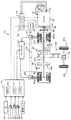
図1は、本発明の一実施形態としてのハイブリッド自動車20の構成の概略を示す構成図であり、図2は、ハイブリッド自動車20に搭載されるエンジン22の構成の概略を示す構成図である。実施例のハイブリッド自動車20は、図示するように、エンジン22と、エンジン22の出力軸としてのクランクシャフト26にダンパ28を介して接続された3軸式の動力分配統合機構30と、動力分配統合機構30に接続された発電可能なモータMG1と、動力分配統合機構30に接続された駆動軸としてのリングギヤ軸32aに取り付けられた減速ギヤ35と、減速ギヤ35に接続されたモータMG2と、車両全体をコントロールするハイブリッド用電子制御ユニット70とを備える。
FIG. 1 is a configuration diagram showing an outline of the configuration of a
エンジン22は、ガソリンまたは軽油などの炭化水素系の燃料により動力を出力する内燃機関として構成されており、図2に示すように、エアクリーナ122により清浄されたエアをスロットルバルブ124を介して吸気管126内に吸入する共に吸入されたエアとインジェクタ128からのガソリンとを混合し、この混合気を吸気バルブ130を介して燃焼室内に吸入して点火プラグによる電気火花により爆発燃焼させて、そのエネルギにより押し下げられるピストン132の往復運動をクランクシャフト26の回転運動に変換する。このエンジン22は、ピストン132とシリンダ134との隙間からクランクケース136内に抜けるブローバイガス(HC,CO,NOx,CO2,H2Oなど)を吸気管126に戻して処理させるブローバイガス還元システム90を備えている。ブローバイガス還元システム90は、クランクケース136内の空間とシリンダヘッドカバー138内の空間とを連絡する連絡通路92と、主としてスロットルバルブ124の上流側からシリンダヘッドカバー138内へエアを導入するエア通路94と、主として流量調節バルブ98を介してシリンダヘッドカバー138内のブローバイガスをスロットルバルブ124の下流側(吸気管126)へ導出するブローバイガス通路96とを備えて構成されており、吸気管126内の負圧に応じて流量調節バルブ98の開度を調整することによりクランクケース136内のブローバイガスを連絡通路92,ブローバイガス通路96を介して吸気管126へ還元する。特に、スロットルバルブ124の下流側(吸気管126)が高負圧となるエンジン22の低負荷運転時には、その負圧によりエア通路94を介してクランクケース136内にエア(新気)が導入され、クランクケース136内を換気(浄化)できるようになっている。これにより、ブローバイガスがクランクケース136内に溜まることによる不都合(例えば、エンジン22内の腐食やエンジンオイルの劣化)を回避することができる。
The
エンジン22は、エンジン用電子制御ユニット(以下、エンジンECUという)24により運転制御(例えば、燃料噴射制御や点火制御,吸入空気量調節制御,ブローバイガス換気制御など)されている。エンジンECU24には、エンジン22を運転制御するのに必要な信号、例えば、クランクシャフト26の回転位置および回転数を検出するクランクポジションセンサ140(図1参照)からのクランクポジションおよび回転数Neや,エンジン22の冷却水の温度を検出する図示しない水温センサからの冷却水温,燃焼室へ吸排気を行なう吸気バルブ130や排気バルブを開閉するカムシャフトの回転位置を検出する図示しないカムポジションセンサからのカムポジション,スロットルバルブ124のポジションを検出する図示しないスロットルバルブポジションセンサからのスロットルポジション,エンジン22の負荷としての吸入空気量を検出するバキュームセンサ148(図1参照)からの吸入空気量Qair,クランクケース136内のNOxの含有量を検出するNOxセンサ142(図1参照)からのNOx含有量などが入力ポートを介して入力されている。また、エンジンECU24からは、エンジン22を運転するための種々の制御信号、例えば、インジェクタへの駆動信号や,スロットルバルブ124のポジションを調節するスロットルモータへの駆動信号,イグニッションコイルへの制御信号,流量調節バルブ98への駆動信号などが出力ポートを介して出力されている。また、エンジンECU24は、ハイブリッド用電子制御ユニット70と通信しており、ハイブリッド用電子制御ユニット70からの制御信号によりエンジン22を運転制御すると共に必要に応じてエンジン22の運転状態に関するデータをハイブリッド用電子制御ユニット70に出力する。
The
動力分配統合機構30は、外歯歯車のサンギヤ31と、このサンギヤ31と同心円上に配置された内歯歯車のリングギヤ32と、サンギヤ31に噛合すると共にリングギヤ32に噛合する複数のピニオンギヤ33と、複数のピニオンギヤ33を自転かつ公転自在に保持するキャリア34とを備え、サンギヤ31とリングギヤ32とキャリア34とを回転要素として差動作用を行なう遊星歯車機構として構成されている。動力分配統合機構30は、キャリア34にはエンジン22のクランクシャフト26が、サンギヤ31にはモータMG1が、リングギヤ32にはリングギヤ軸32aを介して減速ギヤ35がそれぞれ連結されており、モータMG1が発電機として機能するときにはキャリア34から入力されるエンジン22からの動力をサンギヤ31側とリングギヤ32側にそのギヤ比に応じて分配し、モータMG1が電動機として機能するときにはキャリア34から入力されるエンジン22からの動力とサンギヤ31から入力されるモータMG1からの動力を統合してリングギヤ32側に出力する。リングギヤ32に出力された動力は、リングギヤ軸32aからギヤ機構60およびデファレンシャルギヤ62を介して駆動輪63a,63bに出力される。
The power distribution and
モータMG1およびモータMG2は、いずれも発電機として駆動することができると共に電動機として駆動できる周知の同期発電電動機として構成されており、インバータ41,42を介してバッテリ50と電力のやりとりを行なう。インバータ41,42とバッテリ50とを接続する電力ライン54は、各インバータ41,42が共用する正極母線および負極母線として構成されており、モータMG1,MG2の一方で発電される電力を他のモータで消費することができるようになっている。したがって、バッテリ50は、モータMG1,MG2のいずれかから生じた電力や不足する電力により充放電されることになる。なお、モータMG1,MG2により電力収支のバランスをとるものとすれば、バッテリ50は充放電されない。モータMG1,MG2は、いずれもモータ用電子制御ユニット(以下、モータECUという)40により駆動制御されている。モータECU40には、モータMG1,MG2を駆動制御するために必要な信号、例えばモータMG1,MG2の回転子の回転位置を検出する回転位置検出センサ43,44からの信号や図示しない電流センサにより検出されるモータMG1,MG2に印加される相電流などが入力されており、モータECU40からは、インバータ41,42へのスイッチング制御信号が出力されている。モータECU40は、回転位置検出センサ43,44から入力した信号に基づいて図示しない回転数算出ルーチンによりモータMG1,MG2の回転子の回転数Nm1,Nm2を計算している。モータECU40は、ハイブリッド用電子制御ユニット70と通信しており、ハイブリッド用電子制御ユニット70からの制御信号によってモータMG1,MG2を駆動制御すると共に必要に応じてモータMG1,MG2の運転状態に関するデータをハイブリッド用電子制御ユニット70に出力する。
The motor MG1 and the motor MG2 are both configured as well-known synchronous generator motors that can be driven as generators and can be driven as motors, and exchange power with the
バッテリ50は、バッテリ用電子制御ユニット(以下、バッテリECUという)52によって管理されている。バッテリECU52には、バッテリ50を管理するのに必要な信号、例えば,バッテリ50の端子間に設置された図示しない電圧センサからの端子間電圧やバッテリ50の出力端子に接続された電力ライン54に取り付けられた図示しない電流センサからの充放電電流,バッテリ50に取り付けられた図示しない温度センサからの電池温度などが入力されており、必要に応じてバッテリ50の状態に関するデータを通信によりハイブリッド用電子制御ユニット70に出力する。なお、バッテリECU52では、バッテリ50を管理するために電流センサにより検出された充放電電流の積算値に基づいて残容量(SOC)も演算している。
The
ハイブリッド用電子制御ユニット70は、CPU72を中心とするマイクロプロセッサとして構成されており、CPU72の他に処理プログラムを記憶するROM74と、データを一時的に記憶するRAM76と、図示しない入出力ポートおよび通信ポートとを備える。ハイブリッド用電子制御ユニット70には、イグニッションスイッチ80からのイグニッション信号やシフトレバー81の操作位置を検出するシフトポジションセンサ82からのシフトポジション,アクセルペダル83の踏み込み量に対応したアクセル開度Accを検出するアクセルペダルポジションセンサ84からのアクセル開度Acc,ブレーキペダル85の踏み込み量を検出するブレーキペダルポジションセンサ86からのブレーキペダルポジションBP,車速センサ88からの車速Vなどが入力ポートを介して入力されている。なお、ハイブリッド用電子制御ユニット70は、前述したように、エンジンECU24やモータECU40,バッテリECU52と通信ポートを介して接続されており、エンジンECU24やモータECU40,バッテリECU52と各種制御信号やデータのやりとりを行なっている。
The hybrid
こうして構成された実施例のハイブリッド自動車20は、運転者によるアクセルペダル83の踏み込み量に対応するアクセル開度Accと車速Vとに基づいて駆動軸としてのリングギヤ軸32aに出力すべき要求トルクを計算し、この要求トルクに対応する要求動力がリングギヤ軸32aに出力されるように、エンジン22とモータMG1とモータMG2とが運転制御される。エンジン22とモータMG1とモータMG2の運転制御としては、要求動力に見合う動力がエンジン22から出力されるようにエンジン22を運転制御すると共にエンジン22から出力される動力のすべてが動力分配統合機構30とモータMG1とモータMG2とによってトルク変換されてリングギヤ軸32aに出力されるようモータMG1およびモータMG2を駆動制御するトルク変換運転モードや要求動力とバッテリ50の充放電に必要な電力との和に見合う動力がエンジン22から出力されるようにエンジン22を運転制御すると共にバッテリ50の充放電を伴ってエンジン22から出力される動力の全部またはその一部が動力分配統合機構30とモータMG1とモータMG2とによるトルク変換を伴って要求動力がリングギヤ軸32aに出力されるようモータMG1およびモータMG2を駆動制御する充放電運転モード,車速Vが所定車速未満のときにエンジン22の運転を停止してモータMG2から要求動力に見合う動力をリングギヤ軸32aに出力するよう運転制御するモータ運転モードなどがある。
The
次に、実施例のハイブリッド自動車20の動作について説明する。図3は、実施例のハイブリッド自動車20のハイブリッド用電子制御ユニット70により実行される運転制御ルーチンの一例を示すフローチャートである。このルーチンは、トルク変換運転モードと充放電運転モードとのうちのいずれかの運転モードで運転されているときに所定時間毎(例えば、8msec毎)に繰り返し実行される。
Next, the operation of the
運転制御ルーチンが実行されると、ハイブリッド用電子制御ユニット70のCPU72は、まず、アクセルペダルポジションセンサ84からのアクセル開度Accや車速センサ88からの車速V,モータMG1,MG2の回転数Nm1,Nm2を入力する処理を実行する(ステップS100)。ここで、モータMG1,MG2の回転数Nm1,Nm2は、回転数センサ43,44により検出されるモータMG1,MG2の回転子の回転位置に基づいて計算されたものをモータECU40から通信により入力するものとした。
When the operation control routine is executed, first, the
続いて、入力したアクセル開度Accと車速Vとに基づいて駆動軸としてのリングギヤ軸32aに出力すべき要求トルクTr*とエンジン22から出力すべき目標パワーPe*とを設定する(ステップS110)。要求トルクTr*は、実施例では、アクセル開度Accと車速Vと要求トルクTr*との関係を予め定めて要求トルク設定用マップとしてROM74に記憶しておき、アクセル開度Accと車速Vとが与えられると記憶したマップから対応する要求トルクTr*を導出して設定するものとした。図4に要求トルク設定用マップの一例を示す。目標パワーPe*は、設定した要求トルクTr*にリングギヤ軸32aの回転数Nrを乗じたものとバッテリ50の充放電要求パワーPb*とロスLossとの和として計算することができる。なお、リングギヤ軸32aの回転数Nrは、車速Vに換算係数kを乗じることによって求めたり、モータMG2の回転数Nm2を減速ギヤ35の減速比Gr(Nm2/Nr)で除することによって求めたりすることができる。また、充放電要求量Pb*は、バッテリ50の残容量(SOC)やアクセル開度Accなどによって設定することができる。
Subsequently, the required torque Tr * to be output to the ring gear shaft 32a as the drive shaft and the target power Pe * to be output from the
そして、換気実行要求フラグFを入力し(ステップS120)、入力した換気実行要求フラグFの値を調べる(ステップS130)。ここで、換気実行要求フラグFは、クランクケース136内の換気の実行が要求されているか否かを示すフラグであり、図5に例示するフラグ設定処理ルーチンの実行により設定されてRAM76の所定のアドレスに書き込まれたものを読み込むことにより入力するものとした。以下、図3の運転制御ルーチンの説明を一旦中断して、図5のフラグ設定処理ルーチンについて説明する。このルーチンは、所定時間毎(例えば、8msec毎)に繰り返し実行される。
Then, the ventilation execution request flag F is input (step S120), and the value of the input ventilation execution request flag F is checked (step S130). Here, the ventilation execution request flag F is a flag indicating whether or not execution of ventilation in the
フラグ設定処理ルーチンが実行されると、ハイブリッド用電子制御ユニット70のCPU72は、まず、エンジン22の回転数Neと吸入空気量Qairとを入力する(ステップS200)。ここで、エンジン22の回転数Neは、回転数センサとして機能するクランクポジションセンサ140により検出されたものをエンジンECU24から通信により入力するものとした。また、吸入空気量Qairは、バキュームセンサ148により検出されたものをエンジンECU24から通信により入力するものとした。
When the flag setting process routine is executed, the
続いて、入力したエンジン22の回転数Neと吸入空気量Qairとに基づいて単位時間あたりのブローバイガス変化量αを設定し(ステップS210)、設定した単位時間あたりのブローバイガス変化量αを積算することにより、即ち、前回の積算ブローバイガス含有量(前回C)に単位時間あたりのブローバイガス変化量αを加算することにより積算ブローバイガス含有量Cを設定する(ステップS220)。ここで、ブローバイガス変化量αは、実施例では、エンジン22の回転数Neと吸入空気量Qairとブローバイガス変化量αとの関係を予め実験的に定めてブローバイガス変化量設定用マップとしてROM74に記憶しておき、回転数Neと吸入空気量Qairとが与えられるとマップから対応するブローバイガス変化量αを導出して設定するものとした。図6にブローバイガス変化量設定用マップの一例を示す。積算ブローバイガス含有量Cは、実施例では、イグニッションスイッチ80からのイグニッション信号がオンされたときに図示しない初期化ルーチンにより初期値として値0が設定されるものとした。
Subsequently, the blowby gas change amount α per unit time is set based on the input engine speed Ne and the intake air amount Qair (step S210), and the set blowby gas change amount α per unit time is integrated. In other words, the cumulative blowby gas content C is set by adding the blowby gas change amount α per unit time to the previous cumulative blowby gas content (previous C) (step S220). Here, in the embodiment, the blow-by gas change amount α is determined by experimentally determining in advance the relationship among the rotational speed Ne of the
そして、前回このルーチンが実行されたときに設定された換気実行要求フラグFが値1か否か、即ち、既に換気の実行が要求されているか否かを判定する(ステップS230)。換気実行要求フラグFが値1でない(値0)と判定されたときには、積算ブローバイガス含有量Cと換気が必要か否かを判定するための閾値C1refとを比較する(ステップS240)。ここで、閾値C1refは、クランクケース136内の腐食やエンジンオイルの劣化などの影響を与えるおそれのあるブローバイガスの含有量に相当する値として設定される閾値であり、クランクケース136の容量や構造などにより定められる。積算ブローバイガス含有量Cが閾値C1ref以上のときには、クランクケース136内の換気が必要であると判断して換気実行要求フラグFを値1に設定し(ステップS250)、本ルーチンを終了する。一方、積算ブローバイガス含有量Cが閾値C1ref未満のときには、クランクケース136内の換気は不要であると判断してそのまま本ルーチンを終了する。
Then, it is determined whether or not the ventilation execution request flag F set when the routine was executed last time is a
一方、ステップS230で換気実行要求フラグFが値1と判定されたときには、換気が実行されている最中と判断し、積算ブローバイガス含有量Cと換気を終了してもよいか否かを判定するための閾値C2refとを比較する(ステップS260)。ここで、閾値C2refは、クランクケース136内の腐食やエンジンオイルの劣化などの影響を与えるおそれのない程度までクランクケース136内のブローバイガスが排出されたと考えられるブローバイガスの含有量に相当する値として設定される。積算ブローバイガス含有量Cが閾値C2ref未満のときには、クランクケース136内の換気を終了してもよいと判断して換気実行要求フラグFに値0を設定し(ステップS270)、本ルーチンを終了する。一方、積算ブローバイガス含有量Cが閾値C2ref以上のときには、クランクケース136内の換気を続行すべきであると判断してそのまま本ルーチンを終了する。以上がフラグ設定処理である。
On the other hand, when the ventilation execution request flag F is determined to be 1 in step S230, it is determined that ventilation is being performed, and it is determined whether or not the integrated blow-by gas content C and ventilation can be terminated. Is compared with the threshold value C2ref (step S260). Here, the threshold value C2ref is a value corresponding to the content of blow-by gas considered to have been blown-off gas in the
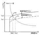
図3の運転制御ルーチンのステップS130の処理に戻って、換気実行要求フラグFが値0のときにはクランクケース136内の換気の実行が要求されていないと判断して目標パワーPe*と燃費を優先した燃費用動作ラインとに基づいて目標回転数Ne*と目標トルクTe*とを設定し(ステップS140)、換気実行要求フラグFが値1のときにはクランクケース136内の換気の実行が要求されていると判断して目標パワーPe*と燃費用動作ラインよりも低トルクを出力する換気用動作ラインとに基づいて目標回転数Ne*と目標トルクTe*とを設定する(ステップS150)。エンジン22の各動作ラインを用いて目標回転数Ne*と目標トルクTe*とを設定する様子を図7に示す。図中、実線は燃費用動作ラインであり、一点鎖線は換気用動作ラインである。図示するように、換気実行要求フラグFが値0のときには、燃費用動作ラインを選択してこの燃費用動作ラインと目標パワーPe*(Ne*×Te*)が一定の曲線との交点であるポイントP0における回転数Ne0とトルクTe0とが目標回転数Ne*と目標トルクTe*として設定され、換気実行要求フラグFが値1のときには、換気用動作ラインを選択してこの換気用動作ラインと目標パワーPe*が一定の曲線との交点であるポイントP1における回転数Ne1とトルクTe1とが目標回転数Ne*と目標トルクTe*として設定される。エンジン22は比較的高負荷で運転した方が効率がよいから、エンジン22の運転ポイントを自由に設定することができる実施例のハイブリッド自動車20では通常比較的高トルクを出力する燃費用動作ライン上の運転ポイントでエンジン22を運転する。このとき、吸気管126内の負圧は小さくなるから、クランクケース136内に含まれるブローバイガスは十分に換気されずにクランクケース136内に長時間留まってエンジン22内の腐食やエンジンオイルの劣化などを招く。燃費用動作ラインよりも低いトルクを出力する換気用動作ライン上の運転ポイントでエンジン22を運転すれば、効率は若干劣るものの吸気管126内の負圧を大きくできるから、新気(エア)をクランクケース136内に導入することができ、クランクケース136内を効果的に換気することができる。換気の実行が要求されたときに換気用動作ラインを用いてエンジン22の運転ポイントを設定するのはこうした理由に基づく。なお、動作ラインは、目標パワーPe*と回転数およびトルクとの関係としてROM74に記憶されている。
Returning to the processing of step S130 of the operation control routine of FIG. 3, when the ventilation execution request flag F is 0, it is determined that the execution of ventilation in the
続いて、設定した目標回転数Ne*とリングギヤ軸32aの回転数Nr(Nm2/Gr)と動力分配統合機構30のギヤ比ρとに基づいてモータMG1の目標回転数Nm1*を計算すると共に計算した目標回転数Nm1*と現在の回転数Nm1とに基づいてモータMG1のトルク指令Tm1*を計算する(ステップS160)。動力分配統合機構30の回転要素における回転数とトルクとの力学的な関係を示す共線図を図8に示す。図中、左のS軸はサンギヤ31の回転数を示し、C軸はキャリア34の回転数を示し、R軸はリングギヤ32の回転数Nrを示す。また、R軸上の2つの太線矢印は、エンジン22を目標回転数Ne*および目標トルクTe*の運転ポイントで運転したときにエンジン22から出力されるトルクTe*がリングギヤ軸32aに伝達されるトルクと、モータMG2から出力されるトルクTm2*が減速ギヤ35を介してリングギヤ軸32aに作用するトルクとを示す。同図におけるサンギヤ31の回転数はモータMG1の回転数Nm1でありキャリア34の回転数はエンジン22の回転数Neであるから、モータMG1の目標回転数Nm1*は、リングギヤ軸32aの回転数Nr(Nm2/Gr)と目標回転数Ne*と動力分配統合機構30のギヤ比ρとに基づいて次式(1)により計算することができる。したがって、計算した目標回転数Nm1*で回転するようトルク指令Tm1*を設定してモータMG1を駆動制御することにより、エンジン22を目標回転数Ne*で回転させることができる。また、モータMG1のトルク指令Tm1*は、実施例では、目標回転数Nm1*と現在の回転数Nm1とを用いてフィードバック制御における関係式(2)により設定するものとした。ここで、式(2)中の右辺第2項の「k1」は比例項のゲインを示し、右辺第3項の「k2」は積分項のゲインを示す。
Subsequently, the target rotational speed Nm1 * of the motor MG1 is calculated and calculated based on the set target rotational speed Ne *, the rotational speed Nr (Nm2 / Gr) of the ring gear shaft 32a, and the gear ratio ρ of the power distribution and
Nm1*=Ne*・(1+ρ)/ρ−Nm2/(Gr・ρ) …(1)
Tm1*=前回Tm1*+k1(Nm1*−Nm1)+k2∫(Nm1*−Nm1)dt …(2)
Nm1 * = Ne * ・ (1 + ρ) / ρ−Nm2 / (Gr ・ ρ) (1)
Tm1 * = previous Tm1 * + k1 (Nm1 * −Nm1) + k2∫ (Nm1 * −Nm1) dt (2)
こうしてモータMG1の目標回転数Nm1*とトルク指令Tm1*とを計算すると、要求トルクTr*とトルク指令Tm1*と動力分配統合機構30のギヤ比ρを用いてモータMG2のトルク指令Tm2*を式(3)により計算する(ステップS170)。モータMG2のトルク指令Tm2*は、図8に示すように、リングギヤ軸32aに要求されるトルクTr*とエンジン22からリングギヤ軸32aに直接伝達されるトルク(−Tm1*/ρ)との偏差を減速ギヤ35のギヤ比Grで除したものとして求めることができる。
When the target rotational speed Nm1 * and the torque command Tm1 * of the motor MG1 are thus calculated, the torque command Tm2 * of the motor MG2 is calculated using the required torque Tr *, the torque command Tm1 *, and the gear ratio ρ of the power distribution and
Tm2*=(Tr*+Tm1*/ρ)/Gr …(3) Tm2 * = (Tr * + Tm1 * / ρ) / Gr (3)
こうしてエンジン22の目標回転数Ne*や目標トルクTe*,モータMG1,MG2のトルク指令Tm1*,Tm2*を設定すると、エンジン22の目標回転数Ne*と目標トルクTe*とについてはエンジンECU24に、モータMG1,MG2のトルク指令Tm1*,Tm2*についてはモータECU40にそれぞれ送信して(ステップS180)、本ルーチンを終了する。目標回転数Ne*と目標トルクTe*とを受信したエンジンECU24は、エンジン22が目標回転数Ne*と目標トルクTe*とによって示される運転ポイントで運転されるようエンジン22における燃料噴射制御や点火制御などの制御を行なう。また、トルク指令Tm1*,Tm2*を受信したモータECU40は、トルク指令Tm1*でモータMG1が駆動されると共にトルク指令Tm2*でモータMG2が駆動されるようインバータ41,42のスイッチング素子のスイッチング制御を行なう。
When the target rotational speed Ne * of the
以上説明した実施例のハイブリッド自動車20によれば、換気の実行が要求されたときには効率のよい燃費用動作ラインよりも低トルクを出力する換気用動作ラインを用いて低負荷領域、即ち、吸気管126内の負圧が高い領域でエンジン22を運転するから、通常時に高効率の燃費用動作ラインを用いて高負荷領域、即ち、吸気管126内の負圧が低い領域でエンジン22を運転することによりクランクケース136内に溜まるブローバイガスを効果的に換気することができる。しかも、エンジン22を低負荷領域で運転することによる吸気管126内の負圧を利用して換気を行なうから、換気システムを変更することなく換気を実行することができる。もとより、要求トルクTr*をリングギヤ軸32aに出力することができる。
According to the
また、実施例のハイブリッド自動車20によれば、ブローバイガスの含有量に基づいて換気の開始と終了とを判断するから、適切なタイミングで換気を実行することができる。これにより、無駄な換気の実行によりエンジン22の効率が低下するのを抑制することができる。しかも、エンジン22の回転数Neおよび吸入空気量Qairに基づいてクランクケース136内のブローバイガスの含有量を推定するから、ブローバイガスの含有量を直接検出するセンサを新たに設けなくてもよい。
Further, according to the
実施例のハイブリッド自動車20では、トルク変換運転モードか充放電運転モードかのいずれかの運転モードが設定されている最中におけるエンジン22内の換気の処理について説明したが、換気の途中でエンジン22の停止条件が成立、即ちモータ運転モードが設定されたときには、換気を終了してもよいと判定されるまで(積算ブローバイガス含有量Cが閾値C2ref未満となるまで)吸気管126内の負圧が高くなる領域でエンジン22の運転(例えば、アイドリング運転)を行なってから、エンジン22の運転を停止させるものとしてもよい。
In the
実施例のハイブリッド自動車20では、エンジン22の運転状態(回転数Ne,吸入空気量Qair)に基づいてクランクケース136内のブローバイガスの含有量を推定するものとしたが、NOxセンサ142によりブローバイガスに含まれるNOxの含有量を検出するものとしてもよい。また、これらを組み合わせて、クランクケース136内に含まれるブローバイガスの含有量を決定するものとしてもよい。
In the
実施例のハイブリッド自動車20では、クランクケース136内のブローバイガスの含有量が閾値C1ref以上となったときに換気の実行を開始し、ブローバイガスの含有量が閾値C2ref未満となったときに換気の実行を終了するものとしたが、ブローバイガスの含有量を検出したり推定したりすることなく、エンジン22を所定時間(例えば、5min)継続して運転したときに換気の実行を開始するものとしたり、所定時間(例えば、60sec)に亘って換気を実行したときに換気の実行を終了するものとしてもよい。
In the
実施例のハイブリッド自動車20では、エンジン22の換気の実行が要求されているときには、換気用動作ラインを用いてエンジン22の目標回転数Neと目標トルクTe*とを設定するものとしたが、換気用動作ラインを用いることなく燃費用動作ラインを用いて設定したエンジン22の運転ポイントを高回転低トルク側にずらして目標回転数Ne*と目標トルクTe*とを設定するものとしてもよい。例えば、目標パワーPe*と燃費用動作ラインとを用いて求めたエンジン22の運転ポイント(回転数,トルク)におけるトルクから所定値を減じて求めたトルクと目標パワーPe*をそのトルクで除して求めた回転数とを目標回転数Ne*および目標トルクTe*として設定するものとしてもよい。
In the
実施例のハイブリッド自動車20では、目標回転数Ne*と目標トルクTe*との設定に用いる動作ラインとして燃費用動作ラインと換気用動作ラインとをROM74に記憶しておくものとしたが、これに加えて燃費用動作ラインよりも高トルクを出力する高トルク用動作ラインなど他の動作ラインを記憶しておくものとしてもよい。こうすれば、駆動軸としてのリングギヤ軸32aに比較的大きなトルクが要求されているときなどにも対処できる。
In the
実施例のハイブリッド自動車20では、モータMG2の動力を減速ギヤ35により減速してリングギヤ軸32aに出力するものとしたが、図9の変形例のハイブリッド自動車120に例示するように、モータMG2の動力をリングギヤ軸32aが接続された車軸(駆動輪63a,63bが接続された車軸)とは異なる車軸(図9における車輪64a,64bが接続された車軸)に出力するものとしてもよい。
In the
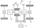
実施例のハイブリッド自動車20では、エンジン22の動力を動力分配統合機構30を介して駆動輪63a,63bに接続された駆動軸としてのリングギヤ軸32aに出力するものとしたが、図10の変形例のハイブリッド自動車220に例示するように、エンジン22のクランクシャフト26に接続されたインナーロータ232と駆動輪63a,63bに動力を出力する駆動軸に接続されたアウターロータ234とを有し、エンジン22の動力の一部を駆動軸に伝達すると共に残余の動力を電力に変換する対ロータ電動機230を備えるものとしてもよい。
In the
また、エンジン22の運転ポイントを比較的自由に設定できるものであれば、こうした実施例のハイブリッド自動車20や変形例のハイブリッド自動車120,220の他、エンジンとエンジンの出力軸に接続された発電機と発電機の発電電力を用いて駆動輪に接続された駆動軸に動力を出力する電動機とを備えるいわゆるシリーズ型のハイブリッド自動車や、駆動輪に接続された駆動軸に変速機を介して取り付けられたエンジンと駆動軸に動力を入出力可能な発電電動機とを備えるいわゆるパラレル型のハイブリッド自動車などの種々のハイブリッド自動車に適用可能である。
If the operating point of the
以上、本発明を実施するための最良の形態について実施例を用いて説明したが、本発明はこうした実施例に何等限定されるものではなく、本発明の要旨を逸脱しない範囲内において、種々なる形態で実施し得ることは勿論である。 The best mode for carrying out the present invention has been described with reference to the embodiments. However, the present invention is not limited to these embodiments, and various modifications can be made without departing from the gist of the present invention. Of course, it can be implemented in the form.
本発明は、自動車産業に利用可能である。 The present invention is applicable to the automobile industry.
20,120,220 ハイブリッド自動車、22 エンジン、24 エンジン用電子制御ユニット(エンジンECU)、26 クランクシャフト、28 ダンパ、30 動力分配統合機構、31 サンギヤ、32 リングギヤ、32a リングギヤ軸、33 ピニオンギヤ、34 キャリア、35 減速ギヤ、37 ギヤ機構、40 モータ用電子制御ユニット(モータECU)、41,42 インバータ、43,44 回転位置検出センサ、50 バッテリ、52 バッテリ用電子制御ユニット(バッテリECU)、54 電力ライン、62 デファレンシャルギヤ、63a,63b,64a,64b 駆動輪、70 ハイブリッド用電子制御ユニット、72 CPU、74 ROM、76 RAM、80 イグニッションスイッチ、81 シフトレバー、82 シフトポジションセンサ、83 アクセルペダル、84 アクセルペダルポジションセンサ、85 ブレーキペダル、86 ブレーキペダルポジションセンサ、88 車速センサ、90 ブローバイガス還元システム、92 連絡通路、94 エア通路、96 ブローバイガス通路、98 流量調節バルブ、122 エアクリーナ、124 スロットルバルブ、126 吸気管、128 インジェクタ、130 吸気バルブ、132 ピストン、134 シリンダ、136 クランクケース、138 シリンダヘッドカバー、140 クランクポジションセンサ、142 NOxセンサ、148 バキュームセンサ、230 対ロータ電動機、232 インナーロータ 234 アウターロータ、MG1,MG2 モータ。 20, 120, 220 Hybrid vehicle, 22 engine, 24 engine electronic control unit (engine ECU), 26 crankshaft, 28 damper, 30 power distribution integration mechanism, 31 sun gear, 32 ring gear, 32a ring gear shaft, 33 pinion gear, 34 carrier , 35 reduction gear, 37 gear mechanism, 40 motor electronic control unit (motor ECU), 41, 42 inverter, 43, 44 rotational position detection sensor, 50 battery, 52 battery electronic control unit (battery ECU), 54 power line 62 differential gear, 63a, 63b, 64a, 64b drive wheel, 70 hybrid electronic control unit, 72 CPU, 74 ROM, 76 RAM, 80 ignition switch, 81 shift lever, 2 shift position sensor, 83 accelerator pedal, 84 accelerator pedal position sensor, 85 brake pedal, 86 brake pedal position sensor, 88 vehicle speed sensor, 90 blow-by gas reduction system, 92 communication passage, 94 air passage, 96 blow-by gas passage, 98 flow rate Regulating valve, 122 Air cleaner, 124 Throttle valve, 126 Intake pipe, 128 Injector, 130 Intake valve, 132 Piston, 134 cylinder, 136 Crankcase, 138 Cylinder head cover, 140 Crank position sensor, 142 NOx sensor, 148 Vacuum sensor, 230 pairs Rotor motor, 232 inner rotor 234 outer rotor, MG1, MG2 motor.
Claims (14)
前記内燃機関の吸気系の負圧を利用して該内燃機関の内部を換気する換気手段と、
前記内燃機関の内部に含まれるブローバイガスの含有量を検出または推定するブローバイガス含有量検出推定手段と、
前記検出または推定されたブローバイガスの含有量に基づいて前記内燃機関の内部の換気の要否を判定する換気要否判定手段と、
前記換気要否判定手段により前記内燃機関の内部の換気が不要と判定されたときには自動車に要求される要求動力が出力されるよう前記内燃機関と前記電動機とを制御する通常時運転制御を行ない、前記換気要否判定手段により前記内燃機関の内部の換気が必要と判定されたときには前記要求動力が出力されると共に前記換気手段による換気が促進されるよう前記内燃機関と前記電動機とを制御する換気時運転制御を行なう制御手段と、
を備えるハイブリッド自動車。 A hybrid vehicle comprising an internal combustion engine and an electric motor, and capable of traveling by power from the electric motor using at least a part of energy from the internal combustion engine,
Ventilation means for ventilating the interior of the internal combustion engine using the negative pressure of the intake system of the internal combustion engine;
Blowby gas content detection estimation means for detecting or estimating the content of blowby gas contained in the internal combustion engine;
Ventilation necessity determination means for determining necessity of ventilation inside the internal combustion engine based on the detected or estimated blowby gas content;
When it is determined that ventilation inside the internal combustion engine is unnecessary by the ventilation necessity determination means, normal operation control is performed to control the internal combustion engine and the electric motor so that the required power required for the automobile is output, Ventilation for controlling the internal combustion engine and the electric motor so that the required power is output and the ventilation by the ventilation means is promoted when the ventilation necessity determination means determines that the internal ventilation of the internal combustion engine is necessary. Control means for performing hourly operation control;
A hybrid car with
前記内燃機関に所定の条件を課した際における該内燃機関のパワーと回転数およびトルクからなる運転ポイントとの関係としての第1の動作線と該第1の動作線よりも低トルクを出力する第2の動作線とを含む複数の動作線を記憶する動作線記憶手段を備え、
前記制御手段は、前記要求動力に基づいて前記内燃機関から出力すべき目標パワーを設定し、前記換気要否判定手段により前記内燃機関の内部の換気が不要と判定されたときには前記設定した目標パワーと前記動作線記憶手段に記憶された前記第1の動作線とに基づいて前記内燃機関の運転ポイントを設定して該設定した運転ポイントで前記内燃機関が運転されると共に前記要求動力が出力されるよう前記内燃機関と前記電動機とを制御し、前記換気要否判定手段により前記内燃機関の内部の換気が必要と判定されたときには前記設定した目標パワーと前記動作線記憶手段に記憶された前記第2の動作線とに基づいて前記内燃機関の運転ポイントを設定して該設定した運転ポイントで前記内燃機関が運転されると共に前記要求動力が出力されるよう前記内燃機関と前記電動機とを制御する手段である
ハイブリッド自動車。 A hybrid vehicle according to any one of claims 1 to 8,
A first operating line as a relationship between the power of the internal combustion engine and an operating point consisting of the rotational speed and torque when a predetermined condition is imposed on the internal combustion engine, and lower torque than the first operating line are output. An operation line storage means for storing a plurality of operation lines including the second operation line;
The control means sets a target power to be output from the internal combustion engine based on the required power, and when the ventilation necessity determination means determines that ventilation inside the internal combustion engine is unnecessary, the set target power And an operating point of the internal combustion engine is set based on the first operating line stored in the operating line storage means and the internal combustion engine is operated at the set operating point and the requested power is output. The internal combustion engine and the electric motor are controlled so that when the ventilation necessity determination means determines that ventilation inside the internal combustion engine is necessary, the set target power and the operation line storage means store the The operation point of the internal combustion engine is set based on the second operation line, the internal combustion engine is operated at the set operation point, and the required power is output. The hybrid vehicle is a means for controlling an internal combustion engine and the electric motor as.
前記内燃機関の吸気系の負圧を利用して該内燃機関の内部を換気する換気手段と、
前記内燃機関に所定の条件を課した際における該内燃機関のパワーと回転数およびトルクからなる運転ポイントとの関係としての第1の動作線と該第1の動作線よりも低トルクを出力する第2の動作線とを含む複数の動作線を記憶する動作線記憶手段と、
自動車に要求される要求動力に基づいて前記内燃機関から出力すべき目標パワーを設定し、所定の換気条件が成立していないときには前記設定した目標パワーと前記動作線記憶手段に記憶された前記第1の動作線とに基づいて前記内燃機関の運転ポイントを設定して該設定した運転ポイントで前記内燃機関が運転されると共に前記要求動力が出力されるよう前記内燃機関と前記電動機とを制御し、前記所定の換気条件が成立したときには前記設定した目標パワーと前記動作線記憶手段に記憶された前記第2の動作線とに基づいて前記内燃機関の運転ポイントを設定して該設定した運転ポイントで前記内燃機関が運転されると共に前記要求動力が出力されるよう前記内燃機関と前記電動機とを制御する制御手段と
を備えるハイブリッド自動車。 A hybrid vehicle comprising an internal combustion engine and an electric motor, and capable of traveling by power from the electric motor using at least a part of energy from the internal combustion engine,
Ventilation means for ventilating the interior of the internal combustion engine using the negative pressure of the intake system of the internal combustion engine;
A first operating line as a relationship between the power of the internal combustion engine and an operating point consisting of the rotational speed and torque when a predetermined condition is imposed on the internal combustion engine, and lower torque than the first operating line are output. Action line storage means for storing a plurality of action lines including a second action line;
The target power to be output from the internal combustion engine is set based on the required power required for the automobile, and when the predetermined ventilation condition is not satisfied, the set target power and the operation line storage means store the first power. The operation point of the internal combustion engine is set based on the operation line of 1, and the internal combustion engine and the electric motor are controlled so that the internal combustion engine is operated at the set operation point and the required power is output. The operating point of the internal combustion engine is set by setting the operating point of the internal combustion engine based on the set target power and the second operating line stored in the operating line storage means when the predetermined ventilation condition is established. And a control means for controlling the internal combustion engine and the electric motor so that the required power is output while the internal combustion engine is operated.
前記内燃機関の出力軸と駆動輪に接続された駆動軸とに接続され、電力と動力の入出力により該内燃機関からの動力の少なくとも一部を前記駆動軸に伝達する動力伝達手段を備え、
前記電動機は、前記駆動軸に動力を入出力可能な電動機であり、
前記制御手段は、前記内燃機関と前記電動機と前記動力伝達手段とを制御する手段である
ハイブリッド自動車。 A hybrid vehicle according to any one of claims 1 to 11,
Power transmission means connected to the output shaft of the internal combustion engine and a drive shaft connected to the drive wheels, and transmitting at least part of the power from the internal combustion engine to the drive shaft by input and output of electric power and power,
The electric motor is an electric motor capable of inputting and outputting power to the drive shaft,
The control means is means for controlling the internal combustion engine, the electric motor, and the power transmission means.
Priority Applications (1)
| Application Number | Priority Date | Filing Date | Title |
|---|---|---|---|
| JP2004017025A JP2005207367A (en) | 2004-01-26 | 2004-01-26 | Hybrid automobile |
Applications Claiming Priority (1)
| Application Number | Priority Date | Filing Date | Title |
|---|---|---|---|
| JP2004017025A JP2005207367A (en) | 2004-01-26 | 2004-01-26 | Hybrid automobile |
Publications (1)
| Publication Number | Publication Date |
|---|---|
| JP2005207367A true JP2005207367A (en) | 2005-08-04 |
Family
ID=34901996
Family Applications (1)
| Application Number | Title | Priority Date | Filing Date |
|---|---|---|---|
| JP2004017025A Pending JP2005207367A (en) | 2004-01-26 | 2004-01-26 | Hybrid automobile |
Country Status (1)
| Country | Link |
|---|---|
| JP (1) | JP2005207367A (en) |
Cited By (1)
| Publication number | Priority date | Publication date | Assignee | Title |
|---|---|---|---|---|
| WO2011092823A1 (en) * | 2010-01-28 | 2011-08-04 | トヨタ自動車株式会社 | CONTROLLER OF INTERNAL COMBUSTION ENGINE, AND DEVICE FOR MEASURING MASS FLOW OF NOx REFLUXED BACK TO INTAKE PASSAGE ALONG WITH BLOW-BY GAS |
-
2004
- 2004-01-26 JP JP2004017025A patent/JP2005207367A/en active Pending
Cited By (5)
| Publication number | Priority date | Publication date | Assignee | Title |
|---|---|---|---|---|
| WO2011092823A1 (en) * | 2010-01-28 | 2011-08-04 | トヨタ自動車株式会社 | CONTROLLER OF INTERNAL COMBUSTION ENGINE, AND DEVICE FOR MEASURING MASS FLOW OF NOx REFLUXED BACK TO INTAKE PASSAGE ALONG WITH BLOW-BY GAS |
| CN102216573A (en) * | 2010-01-28 | 2011-10-12 | 丰田自动车株式会社 | Controller of internal combustion engine, and device for measuring mass flow of nox refluxed back to intake passage along with blow-by gas |
| JP4935933B2 (en) * | 2010-01-28 | 2012-05-23 | トヨタ自動車株式会社 | Control device for internal combustion engine and measurement device for mass flow rate of NOx recirculated to intake passage together with blow-by gas |
| US8469010B2 (en) | 2010-01-28 | 2013-06-25 | Toyota Jidosha Kabushiki Kaisha | Control device for internal combustion engine and measuring device of mass flow rate of NOx recirculated to intake passage with blowby gas |
| CN102216573B (en) * | 2010-01-28 | 2013-07-03 | 丰田自动车株式会社 | Controller of internal combustion engine, and device for measuring mass flow of nox refluxed back to intake passage along with blow-by gas |
Similar Documents
| Publication | Publication Date | Title |
|---|---|---|
| JP4197038B2 (en) | Hybrid vehicle and control method thereof | |
| JP4175371B2 (en) | INTERNAL COMBUSTION ENGINE DEVICE, ITS CONTROL METHOD, AND POWER OUTPUT DEVICE | |
| JP4615037B2 (en) | Hybrid vehicle and control method thereof | |
| JP5700061B2 (en) | Hybrid car | |
| JP2014073693A (en) | Hybrid vehicle | |
| JP4086010B2 (en) | Power output apparatus, automobile equipped with the same, and control method of power output apparatus | |
| JP4085996B2 (en) | Power output apparatus, automobile equipped with the same, and control method of power output apparatus | |
| JP5716425B2 (en) | Hybrid car | |
| JP5966858B2 (en) | Hybrid car | |
| JP4241674B2 (en) | Hybrid vehicle and control method thereof | |
| JP3956937B2 (en) | Automobile and automobile control device | |
| JP2007120382A (en) | Power output device, method for controlling the same and vehicle | |
| JP5126023B2 (en) | INTERNAL COMBUSTION ENGINE DEVICE, VEHICLE HAVING SAME, AND METHOD FOR CONTROLLING INTERNAL COMBUSTION ENGINE DEVICE | |
| JP2007223403A (en) | Power output device, its control method, and vehicle | |
| JP5991145B2 (en) | Hybrid car | |
| JP5655693B2 (en) | Hybrid car | |
| JP2010105626A (en) | Vehicle and control method therefor | |
| JP4438752B2 (en) | POWER OUTPUT DEVICE, ITS CONTROL METHOD, AND VEHICLE | |
| JP2014189081A (en) | Hybrid vehicle | |
| JP4306685B2 (en) | INTERNAL COMBUSTION ENGINE DEVICE, POWER OUTPUT DEVICE, INTERNAL COMBUSTION ENGINE STOP METHOD, AND INTERNAL COMBUSTION ENGINE DEVICE CONTROL METHOD | |
| JP2009279965A (en) | Hybrid vehicle and method of controlling the same | |
| JP4229116B2 (en) | Hybrid vehicle and control method thereof | |
| JP2005207367A (en) | Hybrid automobile | |
| JP2011111951A (en) | Vehicle, and method of controlling exhaust air recirculation | |
| JP2006329172A (en) | Vehicle and its control method |