JP2005205193A - Image quality management system - Google Patents
Image quality management system Download PDFInfo
- Publication number
- JP2005205193A JP2005205193A JP2004355908A JP2004355908A JP2005205193A JP 2005205193 A JP2005205193 A JP 2005205193A JP 2004355908 A JP2004355908 A JP 2004355908A JP 2004355908 A JP2004355908 A JP 2004355908A JP 2005205193 A JP2005205193 A JP 2005205193A
- Authority
- JP
- Japan
- Prior art keywords
- image quality
- image
- report
- quality parameter
- management system
- Prior art date
- Legal status (The legal status is an assumption and is not a legal conclusion. Google has not performed a legal analysis and makes no representation as to the accuracy of the status listed.)
- Granted
Links
Images
Landscapes
- Apparatus For Radiation Diagnosis (AREA)
- Image Processing (AREA)
- Image Analysis (AREA)
Abstract
【課題】模擬被写体による画質評価データから画質の劣化を早期に認識して、画質劣化の原因究明の対応を短時間に指示する画質管理を行うシステムを提供する。
【解決手段】医用画像診断装置に接続される端末に対してネットワークを介して前記医用画像診断装置のメンテナンスレポートを送信するサービスセンタシステムは、前記端末より送信された画像又は画質パラメータを受信する受信手段と、該画像若しくは画質パラメータから、前記医用画像診断装置における画質パラメータを記憶する画質パラメータデータベースと、この画質パラメータデータベースに記憶された画質パラメータが所定の基準値内に含まれるか否か判定する判定手段と、この判定手段による画質パラメータの判定結果を含むレポートを作成するレポート作成手段と、このレポート作成手段により作成された画質パラメータの判定結果を含むレポートをネットワークを介して前記端末に送信する送信手段とを備える。
【選択図】 図1An image quality management system that recognizes deterioration of image quality early from image quality evaluation data of a simulated subject and instructs the investigation of the cause of image quality deterioration in a short time is provided.
A service center system for transmitting a maintenance report of a medical image diagnostic apparatus via a network to a terminal connected to the medical image diagnostic apparatus receives an image or image quality parameter transmitted from the terminal. And an image quality parameter database for storing image quality parameters in the medical image diagnostic apparatus, and whether or not the image quality parameters stored in the image quality parameter database are included in a predetermined reference value from the image and the image quality parameters A determination unit; a report generation unit that generates a report including the determination result of the image quality parameter by the determination unit; and a report including the determination result of the image quality parameter generated by the report generation unit is transmitted to the terminal via the network. Transmitting means.
[Selection] Figure 1
Description
本発明は、病院等の医療機関に据付けられている医用画像機器システムの動作性能判定に係わり、特に医用画像の品質の評価・判定する画質管理を行うシステムに関するものである。 The present invention relates to operation performance determination of a medical image equipment system installed in a medical institution such as a hospital, and more particularly to a system for image quality management that evaluates and determines the quality of medical images.
従来、医療現場に据付けられた医用画像機器の画像品質を、定量的に評価する場合や、機器使用者の依頼がある場合には、これらの機器のサービス会社がファントム(試験用模擬被写体模型)を据付け現地へ持ち込んで、このファントムのスキャン画像データを収集する。収集されたデータを画像のエキスパートエンジニアにより読影し(画像に描出される内容を観察する)、そのデータと基準のデータとの差異を評価することが行なわれていた。この画質の評価は、医用画像機器の種別毎に、予め設定された製品仕様に示される基準値範囲内か、否かで判定される(例えば、特許文献1参照。)。 Conventionally, when quantitatively evaluating the image quality of medical imaging equipment installed in a medical field, or when requested by the equipment user, a service company for these equipment has phantoms (simulated subject models for testing). The phantom scan image data is collected. The collected data is read by an image expert engineer (observing the contents drawn in the image) and the difference between the data and the reference data is evaluated. This evaluation of image quality is determined for each type of medical imaging device based on whether or not it is within a reference value range indicated in a preset product specification (see, for example, Patent Document 1).
一方、医療現場に据付けられた医用画像機器の定量的な画質評価が、サービス担当者が現地に持ち込んだ評価用ファントムのスキャン画像のデータを、解析ソフトが組み込み搭載されたコンピュータに読込んで解析することも、多く行なわれている。 On the other hand, quantitative image quality evaluation of medical imaging equipment installed in the medical field reads and analyzes the scan image data of the evaluation phantom brought to the site by the service staff on a computer with built-in analysis software Many things have also been done.
この解析による結果が、基準値の範囲外になった場合は、解析される項目毎に、対処方法がマニュアル等に記載、表示されるので、これを実施、画質の水準を維持する。
医用画像機器の画質特性は、非常に複雑で微妙に変化する。その理由は、多くの構成部品の特性や、画像生成までの複雑なプロセスの特性の影響を受けて、医用画像が再構成され、出力されるためである。したがって、画質の不具合が発生した場合に、その原因の解明のためにこれらの要素を順次確認するには、試行錯誤による部品の交換及びその確認作業に時間を要し、医用画像検査、診断の業務を長時間に渡り中断しなければならない。さらに、サービス担当者の豊富な経験に基づく技術的能力にも左右されることが問題となっていた。 The image quality characteristics of medical imaging equipment are very complex and subtly change. This is because a medical image is reconstructed and output under the influence of the characteristics of many components and the characteristics of a complicated process up to image generation. Therefore, in the event of image quality defects, it takes time to replace these parts by trial and error and to confirm them in order to confirm these factors in order to elucidate the cause. Business must be interrupted for a long time. Another problem is that it depends on the technical ability based on the abundant experience of service personnel.
本発明は上記のような従来の問題点に鑑みてなされたもので、模擬被写体による画質評価データを、医用画像機器の稼動状況を継続的に蓄積したデータベース、及び故障原因解析データベースにより、画質の劣化を早期に認識して、画質劣化の原因究明の対応を短時間に指示する画質管理を行うシステムを提供することを目的とする。 The present invention has been made in view of the above-described conventional problems. Image quality evaluation data based on simulated subjects is stored in a database that continuously stores the operating status of medical imaging equipment and a failure cause analysis database. It is an object of the present invention to provide a system for performing image quality management that recognizes deterioration at an early stage and instructs the cause of image quality deterioration in a short time.
本発明に係る画質管理システムは、上述した課題を解決するために、医用画像診断装置に接続される端末と、当該端末に対してネットワークを介して前記医用画像診断装置のメンテナンスレポートを送信するサービスセンタシステムとを有する画質管理システムにおいて、前記端末は、前記サービスセンタシステムの第2の送信手段から送信されたレポートを受信する第1の受信手段と、前記医用画像診断装置で撮影された画像又は当該画像に関する画質パラメータを、前記ネットワークを介して送信する第1の送信手段を備え、前記サービスセンタシステムは、前記端末の第1の送信手段により送信された画像又は画質パラメータを受信する第2の受信手段と、前記第2の受信手段により受信された画像若しくは画質パラメータから、前記医用画像診断装置における画質パラメータを記憶する画質パラメータデータベースと、この画質パラメータデータベースに記憶された画質パラメータが所定の基準値内に含まれるか否か判定する判定手段と、この判定手段による画質パラメータの判定結果を含むレポートを作成するレポート作成手段と、このレポート作成手段により作成された画質パラメータの判定結果を含むレポートを前記ネットワークを介して前記端末の第1の受信手段に送信する第2の送信手段とを備えるものである。 In order to solve the above-described problems, an image quality management system according to the present invention is a terminal connected to a medical image diagnostic apparatus and a service for transmitting a maintenance report of the medical image diagnostic apparatus to the terminal via a network In the image quality management system having a center system, the terminal includes a first receiving unit that receives a report transmitted from a second transmitting unit of the service center system, and an image captured by the medical image diagnostic apparatus, A first transmission unit configured to transmit an image quality parameter related to the image via the network; and the service center system receives a second image or image quality parameter transmitted by the first transmission unit of the terminal. From the receiving means and the image or image quality parameter received by the second receiving means, An image quality parameter database for storing image quality parameters in the diagnostic imaging apparatus, determination means for determining whether or not the image quality parameters stored in the image quality parameter database are included in a predetermined reference value, and image quality parameters by the determination means Report creation means for creating a report including the determination result, and second transmission for transmitting the report including the determination result of the image quality parameter created by the report creation means to the first reception means of the terminal via the network Means.
前記画質パラメータは、分解能、コントラスト値、線形値を含むことが望ましい。 The image quality parameter preferably includes a resolution, a contrast value, and a linear value.
そして、前記医用画像診断装置は、好適には、X線CT装置であって、前記レポート作成手段は、画質パラメータ情報として、所望のファントムにおけるCT値線形性、ローコントラスト、空間分解能(MTF)、ノイズ、スライス幅、均一性に関するレポートを作成するものとすることができる。 The medical image diagnostic apparatus is preferably an X-ray CT apparatus, and the report creating means includes, as image quality parameter information, CT value linearity in a desired phantom, low contrast, spatial resolution (MTF), Reports on noise, slice width, and uniformity may be created.
次に、前記サービスセンタシステムは、好適には、前記ネットワークを介して前記医用画像診断装置が設置された環境情報を収集・記憶する環境情報データベースを更に備え、前記レポート作成手段は、前記画質パラメータの判定結果、及び前記環境情報を含むレポートを作成する構成としてもよく、前記ネットワークを介して前記医用画像診断装置の動作情報を収集・記憶する装置動作情報データベースを更に備え、前記レポート作成手段は、前記画質パラメータの判定結果、及び前記医用画像診断装置のキャリブレーションに関係する情報を含むレポートを作成する構成としてもよい。 Next, the service center system preferably further includes an environment information database that collects and stores environment information in which the medical image diagnostic apparatus is installed via the network, and the report creation unit includes the image quality parameter. The report generation means may further include a device operation information database that collects and stores operation information of the medical image diagnostic apparatus via the network. A report including a determination result of the image quality parameter and information related to calibration of the medical image diagnostic apparatus may be created.
また、前記サービスセンタシステムは、好適には、前記ネットワークを介して前記医用画像診断装置の動作情報を収集・記憶する装置動作情報データベースを更に備え、前記レポート作成手段は、所望のファントムにおけるCT値線形性、ローコントラスト、空間分解能(M TF)、ノイズ、スライス幅、均一性に関する情報と共に、前記装置動作情報データベースに記憶された最近のキャリブレーション実施時刻、撮影室の温度・湿度、管球使用量に関する情報を、前記レポートとして作成する構成とすることもできる。 The service center system preferably further includes an apparatus operation information database that collects and stores operation information of the medical image diagnostic apparatus via the network, and the report creation unit includes a CT value in a desired phantom. Information on linearity, low contrast, spatial resolution (MTF), noise, slice width, and uniformity, as well as the most recent calibration execution time stored in the device operation information database, temperature / humidity of the photographic room, and tube use Information regarding the quantity may be created as the report.
ここで、前記最近のキャリブレーション情報は、好適には、X線管への管電圧、管電流、スキャン時間、FOVの組み合わせを収集した実施日であり、前記管球使用量情報はX線管の曝射時間、ローテーションカウントに関する情報であることが望ましい。 Here, the recent calibration information is preferably an implementation date when a combination of tube voltage, tube current, scan time, and FOV to the X-ray tube is collected, and the tube usage information is the X-ray tube information. It is desirable that the information be related to the exposure time and rotation count.
さらに、前記レポート作成手段は、好適には、前記画質パラメータの経時的変化が認識できるように最新の情報及び過去の情報を比較表示するものであってもよい。 Further, the report creation means may preferably display the latest information and past information in a comparative manner so that a change with time of the image quality parameter can be recognized.
加えて、前記判定手段は、好適には、前記画質パラメータが基準値外と判定された場合、前記装置動作情報データベースに記憶された前記撮影室の環境情報及びキャリブレーション情報の少なくとも一方の正常/異常を判定することにより、前記画質パラメータが基準値外と判定された原因が撮影室の環境によるものか或いはどの部品の故障かを解析する構成とすることができる。 In addition, preferably, when the image quality parameter is determined to be out of a reference value, the determination unit preferably includes normal / at least one of the environment information and the calibration information of the imaging room stored in the apparatus operation information database. By determining the abnormality, it is possible to analyze whether the cause that the image quality parameter is determined to be out of the reference value is due to the environment of the photographing room or which component is faulty.
また、前記画質パラメータは、好適には、前記医用画像診断装置でファントムを撮影したときの画質パラメータである。 Further, the image quality parameter is preferably an image quality parameter when a phantom is imaged by the medical image diagnostic apparatus.
さらに、前記第2の送信手段は、好適には、前記判定手段により前記画質パラメータが基準値外と判定された場合、その旨を前記端末、前記医用画像診断装置、及びサービスエンジニアが所有する端末の少なくともいずれかに送信する構成としてもよい。 Further, the second transmission unit preferably has a terminal owned by the terminal, the medical image diagnostic apparatus, and a service engineer when the image quality parameter is determined to be out of a reference value by the determination unit. It is good also as a structure which transmits to at least any one of these.
さらにまた、前記画質管理システムは、好適には、前記判定手段により前記画質パラメータが基準値外と判定された場合、この判定結果に基づいて、前記医用画像診断装置の故障解析手順、故障を修復するための部品、故障を修復するための修復手順の少なくともいずれかを決定するようにしてもよい。 Furthermore, the image quality management system preferably, when the image quality parameter is determined to be out of a reference value by the determination means, based on the determination result, a failure analysis procedure of the medical image diagnostic apparatus, repairing the failure It is also possible to determine at least one of a part to be repaired and a repair procedure to repair the failure.
本発明の画質性能管理システムによれば、故障原因解析データベースに記録されるデータを検索して、画質劣化の原因を明らかにできて、医用画像機器の画質劣化を短時間で復旧できる効果がある。また、医用画像機器の稼動状況を監視するので、画像劣化に関わる機器の状況或いは環境の状況の変化を察知して、画質劣化を未然に防止する効果もある。さらに、予め設定したスキャンプランをユーザが実施して、画質劣化の原因となる機器の稼動条件或いは環境条件などで医師や検査技師などの装置利用者自身が修復対応できる事項を処理できるので、画質劣化状態の期間を最小限にして復帰できる効果も有する。 According to the image quality performance management system of the present invention, it is possible to search the data recorded in the failure cause analysis database to clarify the cause of the image quality deterioration, and to recover the image quality deterioration of the medical imaging device in a short time. . Further, since the operation status of the medical image equipment is monitored, there is an effect of detecting the change of the status of the equipment or the environment related to the image degradation and preventing the image quality degradation. Furthermore, the user can execute a scan plan that has been set in advance, and can handle matters that can be repaired by equipment users such as doctors and laboratory technicians, depending on the operating conditions or environmental conditions of the equipment that causes image quality degradation. There is also an effect that the deterioration state can be minimized and recovered.
(第1の実施形態)
以下、本発明の画質管理システムの第1の実施形態について図面を用いて説明する。図1は、本発明の実施形態を示すブロック図である。
(First embodiment)
Hereinafter, a first embodiment of an image quality management system of the present invention will be described with reference to the drawings. FIG. 1 is a block diagram showing an embodiment of the present invention.
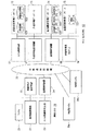
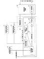
本実施形態の概略の構成は、図1に示すように、公衆通信回線網30と、これに接続されているサービスセンタシステム10、病院システム20、他の病院システム20a〜20nにより構成される。
As shown in FIG. 1, the schematic configuration of the present embodiment includes a public
さらに、このサービスセンタシステム10は、それぞれネットワーク接続されているシステム制御装置11、装置状況管理データベース12、作業手順データベース13、故障履歴管理データベース14、装置品質管理データベース15、作業管理用Webサーバ16、作業手順通知装置17、並びに公衆通信回線網30への通信接続装置18から構成される。
Further, the service center system 10 includes a
また、病院システム20は、病院内に設置され、画質管理の対象となる医用画像機器21、これにネットワーク接続している装置状況監視装置22、ファントム画像解析装置、並びに公衆通信回線網30への通信接続装置24、及び画質評価データを採取する場合に使用する模擬被写体を配置したファントム25から構成される。
In addition, the
さらに病院システム20と同様の構成からなり、同様に画質管理の対象となる他の病院に設置される医用画像機器の病院システム20a〜20nが、同じく公衆通信回線網30に接続している。
Further, the
サービスセンタシステム10の詳細を説明する。 Details of the service center system 10 will be described.
装置状況管理データベース12は、各病院に据付された画像品質管理の対象となる医用画像機器の装置識別符号毎に、その医用画像機器の環境データ、すなわち、機器設置場所の環境温度・湿度等がデータテーブルとして蓄積、記録される環境情報データベース121と、稼動状況データ、すなわち、撮影時のX線管球温度、積算管球稼動時間、及びこれらの観察或いは取得の月日・時刻などがデータテーブルとして蓄積、記録される装置動作情報データベース122とを備える。なお、この装置識別符号毎の医用画像機器の稼動状況データは、対象となる病院システム20の装置状況監視装置22により収集、出力され、公衆通信回線網30を介してサービスセンタシステム10に転送送信されたものである。
The apparatus
また、作業手順データベース13には、画質品質が劣化した場合に、その解析結果のデータを参照して、劣化の原因排除或いは再調整などの復帰作業を行なうためのデータ、すなわち、作業マニュアルのドキュメント番号及びその記載ページ、交換部品型番などの情報・データが作業手順テーブルとして蓄積、記録される。
Further, the
故障履歴管理データベース14には、サービスセンタシステム10が故障対応サービス或いは点検保守サービスを実施した医用画像機器の装置識別符号毎に、記録として、故障発生年月日、故障・画質劣化などの品質問題事項、交換等の対策・対応を行ったレビジョンを含む部品番号などの項目のデータが、データテーブルとして蓄積、記録される故障履歴データベース141を備える。また、故障履歴管理データベース14は、この故障履歴データベース141の画質品質に関連する諸データの抽出結果と機器設計時における設計水準から想定される、画質パラメータ、キャリブレーション、空調などの設定条件がデータテーブルとして蓄積、記録される基準値データベース142と、画質品質の不具合或いは劣化状況を階層構造のカテゴリに分類し、そのカテゴリ毎に原因解析手法及び確認手順などの原因究明の情報がデータテーブルとして蓄積、記録される原因解析データベース143とを備える。なお、基準値データベース142の各基準値は、医用画像機器が適用される、例えば内科、外科、脳神経外科などの臨床分野毎、或いは循環器、呼吸器、消化器、頭部、胸部、腹部などの部位毎に設定されることもある。
In the failure
さらに、装置品質管理データベース15には、対象となる医用画像機器の装置識別符号毎に、工場での製品出荷直前の性能試験における画質性能の結果データ、及び病院へ納入据付け後に行う設置確認における画質性能の結果データ、さらにその後、定期的或いは不具合発生時に実施される画質性能の結果データが、その実施の年月日時データと撮影条件、環境条件と共に画質データテーブル151として記録・保存される。
Further, the apparatus
ここで、本実施形態に係る病院システム20の通信接続装置24は、本発明の第1の受信ユニット及び第1の送信ユニットを有する端末を構成する。同様に本実施形態に係るサービスセンタシステム10の通信接続装置18は、本発明の第2の受信ユニット及び第2の送信ユニットを構成する。また、本実施形態に係る装置品質管理データベース15は、本発明の画質パラメータデータベースを構成する。
Here, the
次に、上記の構成による本実施形態の作用、動作を説明する。 Next, the operation and operation of this embodiment configured as described above will be described.
図1に示す対象の医用画像機器21を設置した病院において、病院システム20の装置状況監視装置22により、装置状況管理データベース12のデータとして、利用環境データ、すなわち設置室の温度、湿度、管球温度、および機器駆動電源の供給電圧変動の連続計測データ、及び稼動データ、すなわち、医用画像機器が例えばX線CT装置などでは、管電流、管電圧、曝射回数或いはスキャン時間で示される管球使用頻度の計測データなどが収集される。さらにこの収集されたデータは、最大・最小値、基準範囲判別、累積などの処理で要約、及び特異状況を抽出して日毎のデータファイルとして装置状況監視装置22に一時的に記録保管される。
In the hospital where the target
この装置状況管理データベース12のデータの収集は、医用画像装置21の稼動の終了を検知するまで所定の時間間隔毎に繰返し行われる。さらに、概ね深夜に1日分の集計が行なわれ、利用環境データ及び稼働データの当日分が、サービスセンタシステム10の装置状況管理データベース12へ通信接続装置24,18を介し、公衆通信回線30を経由して転送される。さらに、1日毎のデータの転送が行なわれた後も、この対象の機器への電力供給を続ける間は、待機中の保管(利用)環境データが継続して測定される。同じく、概ね深夜に、稼働時間、X線曝射時間、および架台回転数積算が、その日の積算結果が決定されて、装置状況管理データベース12に記録される。
The collection of data in the apparatus
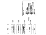
一方、装置状況監視装置22は、図2に示す画質チェックデータ採取の手順により、品質評価データを採取、送信する。図2に示すフロー図では、毎日、或いは毎週などの定期的に設定した画質性能の確認の実施日に、ステップS21で、サービスセンタシステム10が指定し、病院に配備しているファントム25を撮像対象とし、画質性能チェック用の所定のスキャンプランを選択する。なお、配備されるファントム25は、例えば、(1)スライス厚さを計測するために、複数の層構成に成っており、(2)分解能を計測するために、微小な鉄球が埋め込まれ、(3)距離の計測の精度を得るため、四方向に等長のワイヤが埋め込まれている、などの所定の画像品質評価をデータを得るための模擬被写体を配置したものである。また、医用画像機器21の画質チェックデータの撮像条件には、ファントム25の各層の幅をスキャン移動量に設定し、管電圧、管電流などの条件は、医用画像機器21を据付けている臨床分野、すなわち内科、外科、脳神経外科などの対象となる臨床部位に適合する撮像条件が、所定のスキャンプランに設定されるか、これらのいずれかを指定してデータが取得される。
On the other hand, the apparatus
次に、ステップS22で医用画像機器21により、ファントム25を撮像し、画質チェックデータであるファントム画像データを取得する。
Next, in step S22, the
ステップS23で、取得した画質チェックデータが、病院システム20のファントム画像解析装置23に読み込まれて、この画像データの内容を解析する。すなわち、読み込まれたファントム画像データを、ファントム画像解析装置23により、組み込まれたデータ解析ソフトウェアでファントム25に内蔵する標識素材のデジタル画像上の位置と認識して、各種アルゴリズムを用いて定量的に解析する。この解析により、医用画像機器の画質を評価する指標値、X線CT装置では、例えばスライス幅、CT値線形性、空間分解能などの画質に関わる項目の画像データの内容を解析する。また、超音波装置、MRI装置などの他の医用画像機器では、距離計測精度、表示線形性精度、分解能精度などの指標値が解析される。
In step S23, the acquired image quality check data is read into the phantom image analysis device 23 of the
ファントム画像解析装置23によるこの解析結果である画質パラメータは、ステップS24で解析の年月日付と医用画像機器21の装置識別符号と共に、通信接続装置24により公衆通信回線網30を介して、通信接続装置18を通じてサービスセンタシステム10に送信される。
The image quality parameter, which is the analysis result of the phantom image analysis device 23, is connected to the
この受信した解析結果は、装置品質管理データベース15の以前の画質の評価データが記録・保存される画質データテーブル151に、装置識別符号毎に追加記録・保存される。さらに、システム制御装置11に備える画質評価判定プログラムにより、送信されてきたデータが、過去のデータ及び判定基準と比較されて、データを送信してきた医用画像機器21の画質品質が、所定の標準状態を維持しているか、またはメンテナンスを要する劣化の状態であるかが判定される。
The received analysis result is additionally recorded and stored for each device identification code in the image quality data table 151 in which the previous image quality evaluation data of the device
次に、本実施形態のサービスシステムセンタ側のシステム制御装置11で行われる画質性能管理システムのシステムフローについて説明する。
Next, a system flow of the image quality performance management system performed by the
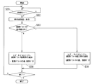
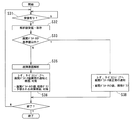
図3は、本実施形態の画質管理システムにおける画質性能チェックデータが送信されて、対象の医用画像装置の画質性能を管理するメインフローのフロー図である。 FIG. 3 is a flowchart of a main flow in which the image quality performance check data in the image quality management system of this embodiment is transmitted and the image quality performance of the target medical image apparatus is managed.
顧客が予め依頼している毎日、或いは毎週などの定期的に設定した画質性能の確認の実施日に、前述の図2のフロー図に示す、指定のファントム25を用いた画質チェックデータの取得が行われると、ステップS24で画質パラメータ、装置状況データ他が、装置識別データと共に送信される。本システムフローのステップS31では、各地の病院に設置される医用画像装置から送信されるこれらのデータを受信する。
The acquisition of image quality check data using the designated
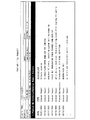
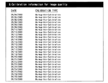
受信すると次のステップS32で、直ちに装置品質管理データベース15に、画質パラメータ他の解析データが記録保存される。装置品質管理データベース15の画質データテーブル151は、図4に示すように、例えば、対象機器の製造シリアル番号、機種、データ採取日、データ採取目的、分解能・コントラスト値・線形値などの画質パラメータ、管電流・管電圧・撮影時間などの撮影条件、管球温度・管球使用量などの管球状況、室温・室湿度などの環境・空調状況がデータテーブルを構成する一覧表(リスト)である。
When received, in the next step S32, analysis data such as image quality parameters are immediately recorded and stored in the apparatus
次に、ステップS33において、ステップS32で記録した画質パラメータの各データが、その機種名を参照して、基準値データベース142に機種毎に予め設定して記録されている画質パラメータの基準値以内であるかを判定する。
Next, in step S33, each data of the image quality parameter recorded in step S32 is within the reference value of the image quality parameter recorded in advance in the
このステップS33で、送信されて記録された画質パラメータが、基準値以内である場合は、ステップS38へ進めて、当該の医用画像装置21の画質性能が、正常な状況である旨及びそのデータを、医療機関の当該医用画像装置の管理担当者にメールを送信してレポートする。また、当該医用画像装置の次回の稼動起動時に、同旨のメッセージを表示する指示を、通信接続装置18,24を経由し公衆通信回線網30を介して医用画像装置21に対し行い、同医用画像装置の実務使用者に対しても、同装置が正常に稼動していることをレポートするなどを行う。更に当該医用画像装置の保守担当をするサービスエンジニア、または担当のサービス営業所に同じく、当該医用画像装置の画質性能が正常な状況である旨をレポートする。
In step S33, if the image quality parameter transmitted and recorded is within the reference value, the process proceeds to step S38, and the fact that the image quality performance of the
一方、ステップS33で、送信されて記録された画質パラメータが、基準値以内でない場合は、ステップS36で、当該の医用画像装置21の画像品質に対する不具合が発生して、装置が故障状態となっている旨を、医療機関の当該医用画像装置の管理担当者にメールを送信してレポートする。または当該医用画像装置の次回の稼動起動時に同旨、及び当該医用画像装置の使用が不可能であり、適切な修理の手配を要する旨のメッセージを表示する指示を、通信接続装置18,24を経由し公衆通信回線網30を介して医用画像装置21に対し行い、同医用画像装置の実務使用者に対し、同装置の使用ができないことをレポートするなどを行う。
On the other hand, if the image quality parameter transmitted and recorded in step S33 is not within the reference value, in step S36, a defect occurs in the image quality of the
上述した処理は、システム制御装置11の図示しないCPUの制御の下、システム制御装置11に搭載されたレポート作成プログラムにより実行される。図5は、この処理における情報の概略の流れを示すものである。レポート作成プログラム40は、情報取得部41、判定情報取得部42、比較判定部43、統計グラフ作成部44、及びレポート作成部45を備える。
The above-described processing is executed by a report creation program installed in the
病院システム20から公衆通信回線網30を経由して、装置通信接続18により受信された種々の情報は、まずシステム制御装置11の情報登録部50に送られる。情報登録部50は、受信した情報を、その種類別に所定のデータベース、例えば、画像の定量値に関する情報については装置品質管理データベース15へ、装置の環境情報や動作情報は装置状況管理データベース12へと送信して、記録保存させる。
Various information received by the
斯かる情報が受信されると、情報取得部41は、装置品質管理データベース15から画像の定量値に関する情報を、そして、装置状況管理データベース12から装置の環境情報や動作情報を呼び出して取得する。これと同時に、判定情報取得部42は、故障履歴管理データベース14の基準値データベース142から、判定基準となる画質パラメータ(基準画質パラメータ)を呼び出して取得する。
When such information is received, the
比較判定部43は、こうして呼び出された画像の定量値に関する情報、装置の環境情報及び動作情報を、基準画質パラメータと比較し、図3に示したステップS33の判定を行う。
The
この判定結果は、これらの情報から統計グラフ作成部44により作成された、各々の項目についてのグラフや表とともにレポート作成部45に送られ、所定のフォーマットのレポートにまとめられる。このレポートは、通信接続装置18内のレポート配信部51により必要なデータ形式の変換が施された後、公衆通信回線網30を経由して病院システム20へと送信される。
This determination result is sent to the
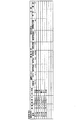
このレポートの幾つかの例を図6及び図7に示す。図6は、レポートの冒頭に表示される医用画像機器のメンテナンス履歴を示すものである。この医用画像機器のメンテナンス履歴は、レポートの要約としての役割も果たしている。 Some examples of this report are shown in FIGS. FIG. 6 shows the maintenance history of the medical image device displayed at the beginning of the report. The maintenance history of the medical imaging device also serves as a summary of the report.
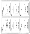
図7は、画質の定量的な解析結果を示すものである。この例では、医用画像機器としてX線CT装置が取り上げられ、CT値線形性、スライス幅、均一性、ノイズ、ローコントラスト、空間分解能(MTF)についての定量値がそれぞれグラフで表示されている。この定量値が、基準画質パラメータの基準値の範囲内にある場合は、図3で示したステップS38の処理が行われ、基準画質パラメータの基準値の範囲内にない場合は、図3で示したステップS36の処理が行われる。 FIG. 7 shows a quantitative analysis result of image quality. In this example, an X-ray CT apparatus is taken up as a medical imaging device, and quantitative values for CT value linearity, slice width, uniformity, noise, low contrast, and spatial resolution (MTF) are displayed in graphs. If this quantitative value is within the range of the reference value of the reference image quality parameter, the process of step S38 shown in FIG. 3 is performed, and if it is not within the range of the reference value of the reference image quality parameter, it is shown in FIG. Step S36 is performed.
(第2の実施形態)
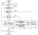
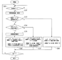
次に、本発明に係る画質管理システムの第2の実施形態について、図を参照して説明する。本実施の形態の画質管理システムは、図8に示すように、画質性能管理システムのシステムフローにおいて、画質パラメータの各データが画質パラメータの基準値以内であるかを判定するステップS33に続いて、ステップS34が追加される点で、第1の実施形態におけるものと基本的に相違し、他の構成、動作は第1の実施形態と実質的に同じであり、同じ符号を付して説明を省略する。
(Second Embodiment)
Next, a second embodiment of the image quality management system according to the present invention will be described with reference to the drawings. As shown in FIG. 8, the image quality management system according to the present embodiment, following the step S33 for determining whether each data of the image quality parameter is within the reference value of the image quality parameter in the system flow of the image quality performance management system, It is basically different from that in the first embodiment in that step S34 is added, and other configurations and operations are substantially the same as those in the first embodiment. Omitted.
本実施形態では、ステップS33で、送信されて記録された画質パラメータが、基準値以内でない場合は、ステップS34で、同じく送信されて記録された装置状況データのキャリブレーション、空調データなどに関する記録データまたは指定事項を、当該機種の基準値データベース142からキャリブレーション、空調データの適正設定基準値データをそれぞれ参照して、これらの適正な設定値からずれていないか判定する。
In the present embodiment, when the image quality parameter transmitted and recorded in step S33 is not within the reference value, in step S34, the recording data related to the calibration, air conditioning data, etc. of the apparatus status data also transmitted and recorded in step S34. Alternatively, the specified items are referred to the appropriate setting reference value data of the calibration and air conditioning data from the
ステップS34の判定で、キャリブレーション或いは空調の設定が適性でない場合には、ステップS37で、当該の医用画像装置21のキャリブレーション或いは空調の設定が適正な設定状況になく、画質性能が損なわれている状況である旨、及びキャリブレーション或いは空調の設定を適正設定基準値に再設定することが必要である旨を、医療機関の当該医用画像装置の管理担当者にメールを送信してレポートする。または当該医用画像装置の次回の稼動起動時に同旨のメッセージ、及び当該医用画像装置のキャリブレーション方法、設置場所の空調機の基準調整インストラクションデータなどを表示する指示を、通信接続装置18,24を経由し公衆通信回線網30を介して医用画像装置21に対し行い、同医用画像装置の実務使用者に対し、同装置の設定が適性でない状況で稼動していることをレポートするなどを行う。
If it is determined in step S34 that the calibration or air conditioning setting is not appropriate, the calibration or air conditioning setting of the
一方、ステップS34の判定で、キャリブレーション或いは空調の設定が適性である場合には、ステップS36で、当該の医用画像装置21の画像品質に対する不具合が発生して、装置が故障状態となっている旨を、医療機関の当該医用画像装置の管理担当者にメールを送信してレポートする。または当該医用画像装置の次回の稼動起動時に同旨、及び当該医用画像装置の使用が不可能であり、適切な修理の手配を要する旨のメッセージを表示する指示を、通信接続装置18,24を経由し公衆通信回線網30を介して医用画像装置21に対し行い、同医用画像装置の実務使用者に対し、同装置の使用ができないことをレポートするなどを行う。
On the other hand, if it is determined in step S34 that the calibration or air conditioning setting is appropriate, in step S36, a defect occurs in the image quality of the
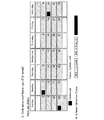
図9及び図10に、ステップS34で、画質を維持するために行われるキャリブレーションの収集履歴のレポート例を示す。この収集履歴は、図9では表形式で表示され、図10では、月間カレンダーの形式で表示されている。 FIG. 9 and FIG. 10 show a report example of calibration collection history performed in step S34 in order to maintain the image quality. This collection history is displayed in a tabular format in FIG. 9, and in a monthly calendar format in FIG.
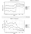
そして、図11は、装置利用環境での温湿度履歴の一例を示している。この図では、所定期間内の平均気温(湿度)に加え、最高気温(湿度)及び最低気温(湿度)もグラフ化されて表示される。 FIG. 11 shows an example of the temperature and humidity history in the device usage environment. In this figure, in addition to the average temperature (humidity) within a predetermined period, the maximum temperature (humidity) and the minimum temperature (humidity) are also graphed and displayed.
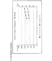
図12は、X線CT装置の管球利用状況を示すグラフである。この図では、曝射回数と積算管球稼動時間とにより利用状況が表示されている。 FIG. 12 is a graph showing the use situation of the tube of the X-ray CT apparatus. In this figure, the usage status is displayed by the number of exposures and the accumulated tube operating time.
(第3の実施形態)
続いて、本発明に係る画質管理システムの第3の実施形態について、図を参照して説明する。本実施の形態の画質管理システムは、図13に示すように、画質性能管理システムのシステムフローにおいて、画質パラメータの各データが画質パラメータの基準値以内であるかを判定するステップS33に続いて、ステップS35が追加される点で、第1の実施形態におけるものと基本的に相違し、他の構成、動作は第1の実施形態と実質的に同じであり、同じ符号を付して説明を省略する。
(Third embodiment)
Next, a third embodiment of the image quality management system according to the present invention will be described with reference to the drawings. As shown in FIG. 13, in the system flow of the image quality performance management system, the image quality management system according to the present embodiment follows step S33 for determining whether each data of the image quality parameter is within the reference value of the image quality parameter. It is basically different from that in the first embodiment in that step S35 is added, and other configurations and operations are substantially the same as those in the first embodiment. Omitted.
前のステップS33で、送信されて記録された画質パラメータが、基準値以内でない場合は、医用画像装置21の故障が疑われるため、ステップS35で、画像品質の低下状況を装置品質管理データベース15内の原因解析データベースに照会し、その原因を解析する。
If the image quality parameter transmitted and recorded in the previous step S33 is not within the reference value, a failure of the
この解析結果を、ステップS36で、当該の医用画像装置21の画像品質に対する不具合が発生して、装置が故障状態となっている旨、及び推定される原因とその対応策に関する情報を、医療機関の当該医用画像装置の管理担当者にメールを送信してレポートする。または当該医用画像装置の次回の稼動起動時に同旨、及び当該医用画像装置の使用が不可能であり、適切な修理の手配を要する旨のメッセージを表示する指示を、通信接続装置18,24を経由し公衆通信回線網30を介して医用画像装置21に対し行い、同医用画像装置の実務使用者に対し、同装置の使用ができないことをレポートするなどを行う。更に当該医用画像装置の保守担当をするサービスエンジニア、または担当のサービス営業所に対応部門に、当該医用画像装置の故障原因解析の結果データをレポートし、原因解析データベース、或いは故障作業データベースの該当故障対応作業に関する作業マニュアル、対応部品などの情報を提示する。
In step S36, the analysis result is obtained from the medical institution as to the fact that a problem with the image quality of the
なお、変形例として、図14に示すように、第2の実施形態に係るシステムフローと第3の実施形態に係るシステムフローとを組み合わせた構成、動作とすることも可能である。 As a modification, as shown in FIG. 14, a configuration and an operation in which the system flow according to the second embodiment and the system flow according to the third embodiment are combined can be used.
上記のように、本実施形態によれば、対象の医用画像機器の画質性能を示す画質パラメータデータ及び管球駆動状況或いは環境状況などの機器状況データを、機器の出荷時から据付、設置稼動後の定期的な複数の時点などで、収集・保存した装置品質管理データベースと、故障履歴管理データベースに備える、医用画像機器の適用部位毎の基準値データベース、及び画質品質の不具合カテゴリ毎に原因解析情報が示される原因解析データベースとに照会或いは検索して、画質品質の劣化の判定と、劣化と判定した場合には、その対応策をサービス担当者及びユーザに提示、指示することができる。 As described above, according to the present embodiment, the image quality parameter data indicating the image quality performance of the target medical image device and the device status data such as the tube driving status or the environmental status are installed from the time of shipment of the device and after the installation operation. Device quality management database collected and stored at multiple regular points in time, a reference value database for each application site of medical imaging equipment, and cause analysis information for each defect category of image quality In response to the inquiry or search of the cause analysis database shown in FIG. 6 and the determination of the deterioration of the image quality and the determination of the deterioration, it is possible to present and instruct the service staff and the user.
したがって、本実施形態により支援されている医用画像機器における画像品質の不具合は、故障原因解析データベースに記録されるデータを検索して、画質劣化の原因を明らかにできて、医用画像機器の画質劣化を短時間で復旧できる効果がある。また、医用画像機器の稼動状況を監視するので、画像劣化に関わる機器の状況或いは環境の状況の変化を察知して、画質劣化を未然に防止する効果もある。さらに、予め設定したスキャンプランをユーザが実施して、画質劣化の原因となる機器の稼動条件或いは環境条件などで医師や検査技師などの装置利用者自身が修復対応できる事項を処理できるので、画質劣化状態の期間を最小限にして復帰できる効果も有する。 Therefore, image quality defects in the medical image equipment supported by the present embodiment can be determined by searching the data recorded in the failure cause analysis database to clarify the cause of image quality deterioration. Can be recovered in a short time. Further, since the operation status of the medical image equipment is monitored, there is an effect of detecting the change of the status of the equipment or the environment related to the image degradation and preventing the image quality degradation. Furthermore, the user can execute a scan plan that has been set in advance, and can handle matters that can be repaired by equipment users such as doctors and laboratory technicians, depending on the operating conditions or environmental conditions of the equipment that causes image quality degradation. There is also an effect that the deterioration state can be minimized and recovered.
10 サービスセンタシステム
11 システム制御装置
12 装置状況管理データベース
121 環境情報データベース
122 装置動作情報データベース
13 作業手順データベース
14 故障履歴管理データベース
141 故障履歴データベース
142 基準値データベース
143 原因解析データベース
15 装置品質管理データベース
151 画質データテーブル
16 作業管理用Webサーバ
17 作業通知装置
18 通信接続装置
20,20a,20n 病院システム
21 医用画像機器
22 装置状況監視装置
23 ファントム画像解析装置
24 通信接続装置
25 ファントム
30 公衆通信回線網
40 レポート作成プログラム
41 情報取得部
42 判定情報取得部
43 比較判定部
44 統計グラフ作成部
45 レポート作成部
51 レポート配信部
10
Claims (12)
前記端末は、
前記サービスセンタシステムの第2の送信手段から送信されたレポートを受信する第1の受信手段と、
前記医用画像診断装置で撮影された画像又は当該画像に関する画質パラメータを、前記ネットワークを介して送信する第1の送信手段とを備え、
前記サービスセンタシステムは、
前記端末の第1の送信手段により送信された画像又は画質パラメータを受信する第2の受信手段と、
前記第2の受信手段により受信された画像若しくは画質パラメータから、前記医用画像診断装置における画質パラメータを記憶する画質パラメータデータベースと、
この画質パラメータデータベースに記憶された画質パラメータが所定の基準値内に含まれるか否か判定する判定手段と、
この判定手段による画質パラメータの判定結果を含むレポートを作成するレポート作成手段と、
このレポート作成手段により作成された画質パラメータの判定結果を含むレポートを前記ネットワークを介して前記端末の第1の受信手段に送信する第2の送信手段と、
を備えることを特徴とする画質管理システム。 In an image quality management system having a terminal connected to a medical image diagnostic apparatus and a service center system that transmits a maintenance report of the medical image diagnostic apparatus to the terminal via a network,
The terminal
First receiving means for receiving a report transmitted from the second transmitting means of the service center system;
A first transmission unit configured to transmit an image captured by the medical image diagnostic apparatus or an image quality parameter related to the image via the network;
The service center system includes:
Second receiving means for receiving an image or image quality parameter transmitted by the first transmitting means of the terminal;
An image quality parameter database for storing image quality parameters in the medical image diagnostic apparatus from the image or image quality parameters received by the second receiving means;
Determining means for determining whether or not the image quality parameter stored in the image quality parameter database is included within a predetermined reference value;
A report creation means for creating a report including the determination result of the image quality parameter by the determination means;
Second transmission means for transmitting a report including the determination result of the image quality parameter created by the report creation means to the first reception means of the terminal via the network;
An image quality management system comprising:
前記レポート作成手段は、画質パラメータ情報として、所望のファントムにおけるCT値線形性、ローコントラスト、空間分解能(MTF)、ノイズ、スライス幅、均一性に関するレポートを作成することを特徴とする請求項1及び2のいずれかに記載の画質管理システム。 The medical image diagnostic apparatus is an X-ray CT apparatus,
The report creating means creates a report on CT value linearity, low contrast, spatial resolution (MTF), noise, slice width, and uniformity in a desired phantom as image quality parameter information. The image quality management system according to any one of 2).
前記レポート作成手段は、前記画質パラメータの判定結果、及び前記環境情報を含むレポートを作成することを特徴とする請求項1から3のいずれかに記載の画質管理システム。 The service center system further includes an environment information database that collects and stores environment information in which the medical image diagnostic apparatus is installed via the network,
The image quality management system according to any one of claims 1 to 3, wherein the report creating unit creates a report including the determination result of the image quality parameter and the environment information.
前記レポート作成手段は、前記画質パラメータの判定結果、及び前記医用画像診断装置のキャリブレーションに関係する情報を含むレポートを作成することを特徴とする請求項1から4のいずれかに記載の画質管理システム。 The service center system further includes an apparatus operation information database that collects and stores operation information of the medical image diagnostic apparatus via the network,
5. The image quality management according to claim 1, wherein the report creating unit creates a report including the determination result of the image quality parameter and information related to calibration of the medical image diagnostic apparatus. system.
前記レポート作成手段は、所望のファントムにおけるCT値線形性、ローコントラスト、空間分解能(M TF)、ノイズ、スライス幅、均一性に関する情報と共に、前記装置動作情報データベースに記憶された最近のキャリブレーション、撮影室の温度・湿度、管球使用量に関する情報を、前記レポートとして作成することを特徴とする請求項3記載の画質管理システム。 The service center system further includes an apparatus operation information database that collects and stores operation information of the medical image diagnostic apparatus via the network,
The report generation means includes a recent calibration stored in the apparatus operation information database, together with information on CT value linearity, low contrast, spatial resolution (MTF), noise, slice width, and uniformity in a desired phantom. 4. The image quality management system according to claim 3, wherein information relating to a temperature / humidity of a photographing room and a tube usage is created as the report.
Priority Applications (1)
| Application Number | Priority Date | Filing Date | Title |
|---|---|---|---|
| JP2004355908A JP4599148B2 (en) | 2003-12-22 | 2004-12-08 | Image quality management system |
Applications Claiming Priority (2)
| Application Number | Priority Date | Filing Date | Title |
|---|---|---|---|
| JP2003424771 | 2003-12-22 | ||
| JP2004355908A JP4599148B2 (en) | 2003-12-22 | 2004-12-08 | Image quality management system |
Publications (3)
| Publication Number | Publication Date |
|---|---|
| JP2005205193A true JP2005205193A (en) | 2005-08-04 |
| JP2005205193A5 JP2005205193A5 (en) | 2008-01-31 |
| JP4599148B2 JP4599148B2 (en) | 2010-12-15 |
Family
ID=34913917
Family Applications (1)
| Application Number | Title | Priority Date | Filing Date |
|---|---|---|---|
| JP2004355908A Expired - Fee Related JP4599148B2 (en) | 2003-12-22 | 2004-12-08 | Image quality management system |
Country Status (1)
| Country | Link |
|---|---|
| JP (1) | JP4599148B2 (en) |
Cited By (10)
| Publication number | Priority date | Publication date | Assignee | Title |
|---|---|---|---|---|
| JP2012189385A (en) * | 2011-03-09 | 2012-10-04 | Fujifilm Corp | Maintenance method of radiograph detection apparatus |
| WO2016174187A1 (en) * | 2015-04-29 | 2016-11-03 | W&H Sterilization S.R.L. | Method and system for monitoring a medical, in particular dental, device |
| JP2019509839A (en) * | 2016-04-04 | 2019-04-11 | コーニンクレッカ フィリップス エヌ ヴェKoninklijke Philips N.V. | Medical imaging system management device |
| EP3486675A1 (en) * | 2017-11-21 | 2019-05-22 | Siemens Healthcare GmbH | Automatic failure detection in mr apparatuses |
| WO2019124750A1 (en) * | 2017-12-19 | 2019-06-27 | (주)리플레이 | Camera calibration method for time slice capturing and apparatus therefor |
| JP2019525320A (en) * | 2016-07-15 | 2019-09-05 | コーニンクレッカ フィリップス エヌ ヴェKoninklijke Philips N.V. | Apparatus for assessing medical device quality |
| WO2020009830A1 (en) * | 2018-07-03 | 2020-01-09 | Covidien Lp | Systems, methods, and computer-readable media for detecting image degradation during surgical procedures |
| JP2020185306A (en) * | 2019-05-17 | 2020-11-19 | キヤノンメディカルシステムズ株式会社 | Medical information processing apparatus |
| JP2022011259A (en) * | 2020-06-30 | 2022-01-17 | コニカミノルタ株式会社 | Dynamic quality control equipment, dynamic quality control program and dynamic quality control method |
| CN115861175A (en) * | 2022-10-28 | 2023-03-28 | 浙江太美医疗科技股份有限公司 | Medical image quality monitoring method and device, electronic equipment and storage medium |
Citations (3)
| Publication number | Priority date | Publication date | Assignee | Title |
|---|---|---|---|---|
| JP2002233504A (en) * | 2001-02-08 | 2002-08-20 | Toshiba Corp | Medical device maintenance program |
| JP2003016212A (en) * | 2001-07-04 | 2003-01-17 | Hitachi Medical Corp | Medical device remote service system and program |
| JP2003260039A (en) * | 2001-12-27 | 2003-09-16 | Toshiba Corp | MRI apparatus and its maintenance support apparatus |
-
2004
- 2004-12-08 JP JP2004355908A patent/JP4599148B2/en not_active Expired - Fee Related
Patent Citations (3)
| Publication number | Priority date | Publication date | Assignee | Title |
|---|---|---|---|---|
| JP2002233504A (en) * | 2001-02-08 | 2002-08-20 | Toshiba Corp | Medical device maintenance program |
| JP2003016212A (en) * | 2001-07-04 | 2003-01-17 | Hitachi Medical Corp | Medical device remote service system and program |
| JP2003260039A (en) * | 2001-12-27 | 2003-09-16 | Toshiba Corp | MRI apparatus and its maintenance support apparatus |
Cited By (14)
| Publication number | Priority date | Publication date | Assignee | Title |
|---|---|---|---|---|
| JP2012189385A (en) * | 2011-03-09 | 2012-10-04 | Fujifilm Corp | Maintenance method of radiograph detection apparatus |
| WO2016174187A1 (en) * | 2015-04-29 | 2016-11-03 | W&H Sterilization S.R.L. | Method and system for monitoring a medical, in particular dental, device |
| US10571904B2 (en) | 2015-04-29 | 2020-02-25 | W&H Sterilization S.R.L. | Method and system for monitoring a medical or dental device |
| JP2019509839A (en) * | 2016-04-04 | 2019-04-11 | コーニンクレッカ フィリップス エヌ ヴェKoninklijke Philips N.V. | Medical imaging system management device |
| JP7090592B2 (en) | 2016-07-15 | 2022-06-24 | コーニンクレッカ フィリップス エヌ ヴェ | A device for assessing the quality of medical devices |
| JP2019525320A (en) * | 2016-07-15 | 2019-09-05 | コーニンクレッカ フィリップス エヌ ヴェKoninklijke Philips N.V. | Apparatus for assessing medical device quality |
| EP3486675A1 (en) * | 2017-11-21 | 2019-05-22 | Siemens Healthcare GmbH | Automatic failure detection in mr apparatuses |
| WO2019124750A1 (en) * | 2017-12-19 | 2019-06-27 | (주)리플레이 | Camera calibration method for time slice capturing and apparatus therefor |
| WO2020009830A1 (en) * | 2018-07-03 | 2020-01-09 | Covidien Lp | Systems, methods, and computer-readable media for detecting image degradation during surgical procedures |
| JP2020185306A (en) * | 2019-05-17 | 2020-11-19 | キヤノンメディカルシステムズ株式会社 | Medical information processing apparatus |
| JP7356816B2 (en) | 2019-05-17 | 2023-10-05 | キヤノンメディカルシステムズ株式会社 | Medical information processing equipment |
| JP2022011259A (en) * | 2020-06-30 | 2022-01-17 | コニカミノルタ株式会社 | Dynamic quality control equipment, dynamic quality control program and dynamic quality control method |
| US12140552B2 (en) | 2020-06-30 | 2024-11-12 | Konica Minolta, Inc. | Dynamic imaging quality control device, storage medium, and dynamic imaging quality control method |
| CN115861175A (en) * | 2022-10-28 | 2023-03-28 | 浙江太美医疗科技股份有限公司 | Medical image quality monitoring method and device, electronic equipment and storage medium |
Also Published As
| Publication number | Publication date |
|---|---|
| JP4599148B2 (en) | 2010-12-15 |
Similar Documents
| Publication | Publication Date | Title |
|---|---|---|
| CN100533446C (en) | Image-quality control system | |
| US7970623B2 (en) | Method of determining maintenance service in accordance with medical equipment condition | |
| CN102973287B (en) | X-ray exposure report system, medical apparatus, and examination protocol distribution system | |
| US8554902B2 (en) | System and method for remotely maintaining devices | |
| CN100518647C (en) | Medical equipment managing apparatus for predicting its future state | |
| US7032132B2 (en) | Reproduction test service apparatus for medical systems, maintenance support information management apparatus, X-ray CT system, and maintenance service center apparatus | |
| US6418334B1 (en) | Method and apparatus for logging and dynamically configuring performance analysis of a medical diagnostic imaging system | |
| JP4585161B2 (en) | Inspection reservation system | |
| JP2006216017A (en) | Automated performance analysis and failure restoration | |
| JP4599148B2 (en) | Image quality management system | |
| US6754545B2 (en) | Method for systematically assessing the quality of medical appliances that are in operation | |
| US8055476B2 (en) | System and method to minimize downtimes of medical apparatuses | |
| WO2011066319A1 (en) | Remote maintenance of medical imaging devices | |
| US20090089091A1 (en) | Examination support apparatus, method and system | |
| JP2000271089A (en) | Quality control system for medical diagnostic device | |
| CN109661626B (en) | System and method for diagnosing an automation system | |
| JP2003260039A (en) | MRI apparatus and its maintenance support apparatus | |
| JP2005205193A5 (en) | ||
| JP2005110794A (en) | MEDICAL DEVICE MANAGEMENT DEVICE, MEDICAL DEVICE MANAGEMENT METHOD, MANAGEMENT SYSTEM, AND MONITORING DEVICE | |
| JP7484988B2 (en) | Analysis and Processing System | |
| Maki et al. | Audit of data from examination image headers collected for quality assurance in the ECOG‐ACRIN EA1151 tomosynthesis mammographic imaging screening trial (TMIST) | |
| JP2005245815A (en) | Medical test equipment readjustment support system | |
| Wang et al. | Establishment and practice of 5 layers guarantee system for CT/MR equipment quality management based on multi-party cooperation | |
| Honeyman-Buck et al. | PACS quality control and automatic problem notifier | |
| KR101932879B1 (en) | Management system for medical device |
Legal Events
| Date | Code | Title | Description |
|---|---|---|---|
| A521 | Request for written amendment filed |
Free format text: JAPANESE INTERMEDIATE CODE: A523 Effective date: 20071205 |
|
| A621 | Written request for application examination |
Free format text: JAPANESE INTERMEDIATE CODE: A621 Effective date: 20071205 |
|
| A977 | Report on retrieval |
Free format text: JAPANESE INTERMEDIATE CODE: A971007 Effective date: 20100527 |
|
| A131 | Notification of reasons for refusal |
Free format text: JAPANESE INTERMEDIATE CODE: A131 Effective date: 20100601 |
|
| A521 | Request for written amendment filed |
Free format text: JAPANESE INTERMEDIATE CODE: A523 Effective date: 20100802 |
|
| TRDD | Decision of grant or rejection written | ||
| A01 | Written decision to grant a patent or to grant a registration (utility model) |
Free format text: JAPANESE INTERMEDIATE CODE: A01 Effective date: 20100831 |
|
| A01 | Written decision to grant a patent or to grant a registration (utility model) |
Free format text: JAPANESE INTERMEDIATE CODE: A01 |
|
| A61 | First payment of annual fees (during grant procedure) |
Free format text: JAPANESE INTERMEDIATE CODE: A61 Effective date: 20100927 |
|
| R150 | Certificate of patent or registration of utility model |
Ref document number: 4599148 Country of ref document: JP Free format text: JAPANESE INTERMEDIATE CODE: R150 Free format text: JAPANESE INTERMEDIATE CODE: R150 |
|
| FPAY | Renewal fee payment (event date is renewal date of database) |
Free format text: PAYMENT UNTIL: 20131001 Year of fee payment: 3 |
|
| S111 | Request for change of ownership or part of ownership |
Free format text: JAPANESE INTERMEDIATE CODE: R313117 |
|
| R350 | Written notification of registration of transfer |
Free format text: JAPANESE INTERMEDIATE CODE: R350 |
|
| S533 | Written request for registration of change of name |
Free format text: JAPANESE INTERMEDIATE CODE: R313533 |
|
| R350 | Written notification of registration of transfer |
Free format text: JAPANESE INTERMEDIATE CODE: R350 |
|
| LAPS | Cancellation because of no payment of annual fees |