JP2005201846A - Erroneous reading preventive mechanism for measuring instrument device - Google Patents
Erroneous reading preventive mechanism for measuring instrument device Download PDFInfo
- Publication number
- JP2005201846A JP2005201846A JP2004010434A JP2004010434A JP2005201846A JP 2005201846 A JP2005201846 A JP 2005201846A JP 2004010434 A JP2004010434 A JP 2004010434A JP 2004010434 A JP2004010434 A JP 2004010434A JP 2005201846 A JP2005201846 A JP 2005201846A
- Authority
- JP
- Japan
- Prior art keywords
- lens
- display
- display unit
- cover
- instrument device
- Prior art date
- Legal status (The legal status is an assumption and is not a legal conclusion. Google has not performed a legal analysis and makes no representation as to the accuracy of the status listed.)
- Pending
Links
Images

Abstract
Description
本発明は、電力量計、ガスメータ、水道メータなどの計量装置や電圧計、電流計などの計測装置を含む計器装置に用いられ、透明の窓部材を介して計量値又は計測値を表示若しくは指示する表示部等を視認し得るように構成された計器装置の誤読防止機構に関する。 The present invention is used for measuring devices such as watt-hour meters, gas meters, water meters, and measuring devices such as voltmeters and ammeters, and displays or indicates measured values or measured values through a transparent window member. The present invention relates to a misread prevention mechanism of an instrument device configured to be able to visually recognize a display unit or the like.
電力量計、ガスメータ、水道メータなどの計器装置にあっては、検針時に表示部に表示される計量値を視認できるように構成されており、表示される計量値から使用量を算定し、使用料金を確定するために利用される。このため、視認による検針にあっては、表示部に表示された計量値を正確に読み取ることが要請され、誤読を回避する必要がある。特に、見えにくい位置に設置された計器装置にあっては、反射鏡等を使用して検針する場合等もあり、表示部の表示が小さいと、表示内容を明確に把握することが困難となる。 Meter devices such as watt-hour meters, gas meters, and water meters are configured so that the measured value displayed on the display unit can be seen at the time of meter reading. Used to determine the price. For this reason, in the meter reading by visual recognition, it is required to accurately read the measurement value displayed on the display unit, and it is necessary to avoid misreading. In particular, in instrument devices installed in difficult-to-see positions, there are cases where the meter is read using a reflecting mirror, etc. If the display on the display is small, it is difficult to clearly grasp the display contents .
また、検針者の全てが視力や認識力に長けているわけではないので、検針者の誤読を防ぐには、表示内容の明瞭な表示が必要となる。このような要請は、電力量計などの計量装置だけでなく、電圧計や電流計などの計測装置においても生じている。 In addition, since not all meter readers are good at visual acuity and recognition power, clear display of display contents is necessary to prevent misreading by meter readers. Such a request is generated not only in a measuring device such as a watt hour meter but also in a measuring device such as a voltmeter or an ammeter.
ところで、表示内容を明瞭に表示させる機構としては、従来、指示器ケースの窓ガラスの外端面を凸レンズ状に形成し、ケース内に収容された指示計の指示値を見やすくしたものや(特許文献1)、水道メータの本体の上部にガラス板を介して凸レンズを配置し、この凸レンズの上方に設けられた検針窓に凸レンズ効果を有するレンズ部を備えた検針窓キャップを設け、凸レンズと検針窓キャップのレンズ部とによる二重の拡大作用により目盛りを拡大して見えるようにしたもの(特許文献2)、カバーの上端面に設けられた表示用の開口部に透明な窓部材を設け、この窓部材を凸レンズ状に形成して表示部を広角度で見ることができるようにしたもの(特許文献3)などが考えられている。 By the way, as a mechanism for clearly displaying the display contents, conventionally, the outer end surface of the window glass of the indicator case is formed in a convex lens shape, and the indication value of the indicator accommodated in the case is easy to see (Patent Literature 1) A convex lens is arranged on the upper part of the main body of the water meter through a glass plate, a metering window cap provided with a lens portion having a convex lens effect is provided on the metering window provided above the convex lens, and the convex lens and the metering window A scale that can be seen to be enlarged by a double enlargement action with the lens part of the cap (Patent Document 2), a transparent window member is provided in a display opening provided on the upper end surface of the cover, A window member formed in the shape of a convex lens so that the display unit can be viewed at a wide angle is considered (Patent Document 3).
また、数字車の上部と窓ガラスとの間に透明な曇り防止板を配置し、この曇り防止板に、数字車の上部に位置して上面が平滑面で下面が凸の凸レンズを形成して、数字車の数字を拡大表示させて検針を容易にする構成も公知となっている(特許文献4)。 In addition, a transparent anti-fogging plate is placed between the upper part of the number wheel and the window glass, and a convex lens is formed on the anti-fog plate that is located at the upper part of the number wheel and has a smooth upper surface and a convex lower surface. A configuration that facilitates meter reading by enlarging and displaying the numbers of a number wheel is also known (Patent Document 4).
しかしながら、上述した特許文献1乃至3に係る構成は、計器装置の外側へ凸となるレンズ部を設けることで表示部の表示を拡大させるようにしているので、レンズ部の凸状表面が外部に表出して異物などと接触しやすくなり、傷つきやすい状態となっている。また、レンズ部の凸状表面が外側に向けられていると、レンズ部の表面に埃が溜まりやすいものとなる。このため、表示部の明瞭な表示を確保するためにレンズ部を設けたにもかかわらず、レンズ部に傷がついたり埃が付着することでかえって見えにくくなり、誤読を誘発する恐れがある。
However, since the configuration according to
また、特許文献4の構成は、数字車と窓ガラスとの間に曇り防止板を配置させるようにした特有の構成を前提とするものであり、各種計器装置にこのような構成を採用することは現実的ではない。
Moreover, the structure of
本発明は、以上のような事情に鑑みてなされたものであり、レンズ部に傷がついたり埃が付着して誤読を誘発する恐れがなく、また各種計器装置に容易に採用することが可能な計器装置の誤読防止機構を提供することを主たる課題としている。 The present invention has been made in view of the circumstances as described above, and there is no possibility that the lens portion is scratched or dust is attached to cause misreading, and can be easily adopted in various instrument devices. It is a main problem to provide a misreading prevention mechanism for a simple instrument device.
上記課題を達成するために、この発明に係る計器装置の誤読防止機構は、計量値又は計測値を表示若しくは指示する表示部と、前記表示部を覆うように設けられると共に前記表示部を見通せる窓孔を備えたカバー部材とを備え、前記窓孔に透明な窓部材を装着して構成される計器装置にあって、前記窓部材の少なくとも前記表示部と対向する内面に拡大表示可能なレンズ部を設けたことを特徴としている(請求項1)。 In order to achieve the above object, a misreading prevention mechanism for an instrument device according to the present invention includes a display unit that displays or indicates a measured value or a measured value, and a window that is provided so as to cover the display unit and through which the display unit can be seen. A lens unit capable of displaying an enlarged image on at least an inner surface of the window member facing the display unit. (Claim 1).
したがって、少なくとも表示部の手前に対向配置された窓部材のレンズ部により表示部の表示を拡大表示させることが可能となり、表示内容を正確に把握することが可能となる。また、レンズ部は、窓部材の内面に形成されているので、表面に異物が接触して傷がついたり埃が付着する恐れがなく、表示部の表示を見誤ることもなくなる。 Therefore, the display of the display unit can be enlarged and displayed by the lens unit of the window member disposed so as to face at least in front of the display unit, and the display contents can be accurately grasped. In addition, since the lens portion is formed on the inner surface of the window member, there is no possibility of foreign matter coming into contact with the surface and scratching or dust adhering, and display on the display portion will not be mistaken.
ここで、拡大表示可能なレンズ部としては、凸レンズ状に形成されるものであっても、凹レンズ状に形成されるものであっても、フレネルレンズ状に形成されるものであってもよい。また、窓部材に形成されるレンズ部は、表示部に対して直接対向配置されるものであってもよいが、計器装置を、表示部を覆うように設けられたガラスカバーを有する計器本体と、前記ガラスカバーを覆うように設けられて前記窓孔を有するカバー部材とを有して構成する場合には、レンズ部をガラスカバーを介して表示部と対向させるようにしてもよい(請求項2)。このような構成においても、少なくとも表示部をレンズ部によって拡大表示させることが可能となり、表示内容を正確に把握することが可能となる。また、表示部とレンズ部との間にガラスカバーが設けられていることから、表示部とレンズ部との距離を確保することが可能となり、レンズ部の厚みを薄くすることが可能となる。 Here, the lens portion that can be magnified may be formed in a convex lens shape, a concave lens shape, or a Fresnel lens shape. Further, the lens part formed on the window member may be disposed directly opposite to the display part, but the instrument device includes an instrument body having a glass cover provided so as to cover the display part. In the case of including a cover member provided so as to cover the glass cover and having the window hole, the lens unit may be opposed to the display unit through the glass cover. 2). Even in such a configuration, at least the display unit can be enlarged and displayed by the lens unit, and the display content can be accurately grasped. In addition, since the glass cover is provided between the display unit and the lens unit, the distance between the display unit and the lens unit can be secured, and the thickness of the lens unit can be reduced.
さらに、レンズ部は、窓部材に一体に成形されるものであっても、別体に成形されて後付けされるものであってもよい(請求項3、4)。前者の構成においては、窓部材の成形時にレンズ部が同時に成形されるので、レンズ部を後付けする作業工程が不要となり、また、レンズ部を設ける位置を微調整する必要もなくなり、新規に製造する計器装置に適したものとなる。これに対し、後者の構成においては、既存の計器装置の窓部材にレンズ部を後付けすることが可能となるので、計器装置を取り替える必要がなくなり、既存の計器装置に適したものとなる。
Further, the lens portion may be formed integrally with the window member, or may be formed separately and attached later (
以上の構成は、電力量計、水道メータ、ガスメータなどの計量装置や電圧計、電流計などの計測装置のように、計量値又は計測値が表示若しくは指示される表示部を覆うようにカバー部材が設けられ、このカバー部材の窓孔に透明な窓部材が装着されて窓部材を介して表示部を視認することが可能な計器装置であれば適用し得るものであり、例えば計器装置が電力量計である場合には、検針時において表示部の表示と計器番号(製造番号)とを視認する必要があるので、レンズ部を、表示部を含む検針時において視認が必要となる全ての箇所と対向するように設けてもよい(請求項5)。 The above configuration is a cover member so as to cover a display unit where a measured value or a measured value is displayed or indicated, such as a measuring device such as a watt hour meter, a water meter, or a gas meter, or a measuring device such as a voltmeter or an ammeter. This is applicable to any instrument device in which a transparent window member is attached to the window hole of the cover member so that the display unit can be visually recognized through the window member. In the case of a meter, since it is necessary to visually check the display part and the instrument number (manufacturing number) at the time of meter reading, the lens part must be visually recognized at the time of meter reading including the display part. (Claim 5).
以上述べたように、この発明によれば、窓孔に取り付けられた透明な窓部材の少なくとも表示部と対向する内面に拡大表示可能なレンズ部を設けるようにしたので、表示部を含む表示部分を拡大表示させて表示内容を正確に把握することが可能となり、また、レンズ部表面に異物が接触して傷が付いたり、埃が付着することを避けることができるので、傷や埃で誤読を誘発する恐れがなくなる。さらに、窓部材の内面にレンズ部を設けるようにしたので、レンズ部を付設する格別な部材を必要とせず、各種計器装置に同様の構成を採用することが可能となる。 As described above, according to the present invention, since the lens portion that can be enlarged and displayed is provided on at least the inner surface facing the display portion of the transparent window member attached to the window hole, the display portion including the display portion is provided. It is possible to zoom in on the display to accurately grasp the display contents, and it is possible to prevent foreign matter from coming into contact with the surface of the lens and scratching or dust from being attached. There is no fear of triggering. Furthermore, since the lens portion is provided on the inner surface of the window member, a special member for attaching the lens portion is not required, and the same configuration can be adopted for various instrument devices.
ここで、窓部材のレンズ部は、表示部と直接対向配置されるものであっても、ガラスカバーを介して対向配置されるものであってもよく、後者の構成においては、少なくともガラスカバーが介在されている分、表示部とレンズ部との距離が大きく確保されるので、レンズ部の厚みを薄くすることが可能となる。 Here, the lens portion of the window member may be disposed directly opposite to the display portion, or may be disposed oppositely through the glass cover. In the latter configuration, at least the glass cover is provided. Since the distance between the display unit and the lens unit is ensured by the amount of interposition, the thickness of the lens unit can be reduced.
また、レンズ部を窓部材と一体に成形する構成とすれば、窓部材にレンズ部を後付けする作業工程が不要となり、レンズ部の位置を微調整する必要もなくなるので、取り付け不良による表示部の誤読を回避することが可能となる。 In addition, if the lens part is formed integrally with the window member, a work process for retrofitting the lens part to the window member becomes unnecessary, and it is not necessary to finely adjust the position of the lens part. It becomes possible to avoid misreading.
これに対し、レンズ部を窓部材と別体に成形して窓部材に後付けする構成とすれば、レンズ部が設けられていない既存の計器装置に対してもレンズ部を付加することが可能となり、計器装置に取り替える必要がなくなる。 On the other hand, if the lens part is formed separately from the window member and is retrofitted to the window member, the lens part can be added even to an existing instrument device that does not have a lens part. This eliminates the need to replace the instrument device.
さらに、電力量計などのように、検針時に表示部に加えて計器装置の識別番号などをも視認する必要がある場合には、レンズ部を表示部を含む検針時において視認が必要となる全ての箇所と対向するように設けることで、検針時に必要な全ての情報を正確に視認することが可能となる。 Furthermore, when it is necessary to visually recognize the identification number of the instrument device in addition to the display unit at the time of meter reading, such as an watt-hour meter, all the items that need to be visually confirmed at the time of meter reading including the display unit are included. By providing it so as to face this part, it becomes possible to accurately visually recognize all information necessary for meter reading.
以下、この発明の最良の実施形態を添付図面を参照しながら説明する。 DESCRIPTION OF THE PREFERRED EMBODIMENTS The best embodiment of the present invention will be described below with reference to the accompanying drawings.
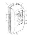
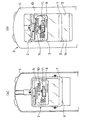
図1乃至図3において、計器装置の一例として電力量計1を用いた場合が示されている。この例において、電力量計1は、計量器2を収容ボックス3に収容して構成されているもので、収容ボックス3は、絶縁性を有する合成樹脂製のベース4とカバー部材5とによって構成されている。
In FIG. 1 thru | or FIG. 3, the case where the watt-
ベース4は、その前面に計量器2が螺子止めなどの手段によって装着されており、計量器2に接続される電線を背面側から前面側に挿通させるようにしている。このベースに取り付けられる計量器2は、それ自体公知のもので、ガラスカバー6の内部に計器本体7を収容し、この計器本体7の前面に銘板8および計量盤9が配設されているものである。
The
銘板8には、型の記号、型式承認番号、計器固有の定格電圧、定格電流、定格周波数、計器定数に加え、計器本体7を識別する製造番号10などが表示され、この例においては、中程に表示孔11が形成され、この表示孔11に液晶表示からなる現字形の計量盤9を臨ませている。この表示孔11を介して視認し得る計量盤9によって計量値を表示する表示部が構成されている。
The
カバー部材5は、背面が開口する略直方体形状に形成された不透明色のもので、ベース4の前面に着脱可能に装着されて計量器2を覆うように設けられている。このカバー部材5の前面には、銘板8及び計量盤9を見通せる窓孔12が形成され、この例において窓孔12は、計器本体7の全体が見通せるように上下方向に延設された略矩状に形成されている。
The
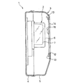
そして、この窓孔12には、カバー部材5の内側から孔縁に設けられた保持枠13によりガラス板又は合成樹脂板などからなる透明な窓部材14が装着されている。この窓部材14の内面には、凸レンズ状に形成されたレンズ部15が一体に設けられている。このレンズ部15は、ガラスカバー6を介して少なくとも計量盤9と対向する部分、この例においては、検針時において視認が必要となる計量盤9及び製造番号10の表示部分と対向する部分に長円形状に形成されている。
A
ここで、レンズ部15は、正面から見たときに計量盤9の表示と製造番号とが拡大表示されるように中心部の厚みを最も厚くし、周辺部で徐々に薄くするようにしてもよいが、電力量計1においては、地面から1.8m〜2.2mの高さに設置されるので、下方から見上げたときに計量盤9の表示と製造番号10の表示とが拡大表示されるように、レンズ部15の厚みを調整してもよい。
Here, the
したがって、上述の構成においては、検針時に視認する必要がある計量盤9の表示と製造番号10がレンズ部15によって拡大表示されるので、表示部分を正確に認識することが可能となり、誤読を防ぐことが可能となる。
Therefore, in the above-described configuration, the display of the weighing
また、窓孔12に設けられた透明な窓部材14の内面にレンズ部15が設けられるので、レンズ部15が外部から異物と接触して傷つくこともなく、また、埃がレンズ部上に溜まることもないので、傷や埃によって計量盤9の表示や製造番号10が見えにくくなって誤読を誘発する恐れもなくなる。
Further, since the
特に、上述のようにカバー部材5を着脱し得るような計器装置においては、カバー部材5を一時的に取り外し、表面を下に向けて置くこともあるが、このような場合でも、レンズ部15は窓部材14の内面に形成されているので、レンズ部表面を傷つけたり破損させる不都合がなくなる。
In particular, in an instrument device in which the
さらに、上述の構成においては、レンズ部15が窓部材14に一体に形成されているので、窓部材14にレンズ部15を後付けする作業工程が不要となり、また、レンズ部15の位置を微調整する必要もないので、取り付け不良による表示部の誤読も回避することが可能となる。
Furthermore, in the above-described configuration, since the
尚、上述の構成においては、レンズ部15を窓部材14と一体に形成した例を示したが、レンズ部15を別体に形成し、接着剤等によって後付けするようにしてもよい。このような構成によれば、レンズ部が設けられていない既存の計器装置に対して、レンズ部を取り付けて表示部等を拡大表示させることが可能となり、既存の計器装置を取り替える必要がなくなる。また、上述の構成においては、レンズ部を凸レンズ状に形成した例を示したが、拡大表示が可能な形状であれば、凹レンズ状に形成しても、フレネルレンズ状に形成してもよい。
In the above configuration, the
また、上述の構成においては、計器装置の一例として電力量計1を用いた場合を示したが、ガスメータや水道メータなどのように、計量値を表示する表示部と、表示部を覆うように設けられた窓孔を有するカバー部材と、窓孔に透明な窓部材が装着されてこの窓部材を介して表示部等を視認することが可能な他の計量装置においても同様の構成を採用することが可能である。
Moreover, in the above-mentioned structure, the case where the watt-
さらに、上述の構成においては、ガラスカバー6を介して視認が必要となる計量盤9と製造番号10の表示箇所とに対向させてレンズ部15を設けるようにしたが、計量値を表示する計量盤のみと対向するようにレンズ部を設けても、ガラスカバー6を介在させずに視認が必要となる箇所にレンズ部15を直接対向して設けるようにしてもよい。また、レンズ部15の大きさや形状も視認が必要となる箇所に合わせて適宜変更してもよい。
Further, in the above-described configuration, the
以上の構成においては、電力量計などの計量装置の例を示したが、電圧計や電流計などのような計測装置の窓部材に対しても同様の構成を採用してもよい。例えば、図4に示されるように、指針16によって計測値を指示する表示部17と、この表示部17を覆うように設けられると共に表示部17を見通せる窓孔18を備えたカバー部材19とを備え、窓孔18に透明な窓部材20が装着されている電圧計21に対して、表示部17と対向する窓部材20の内面に拡大表示可能なレンズ部22を設けるようにしてもよい。具体的には、同図に示されるように、指針16が移動する目盛り23の表示部分と対向させてレンズ部22を弧状に形成するようにしてもよい。
In the above configuration, an example of a metering device such as a watt hour meter is shown, but the same configuration may be adopted for a window member of a measuring device such as a voltmeter or an ammeter. For example, as shown in FIG. 4, a
本発明は、窓部に設けられた透明な窓部材を介して表示部を視認するような各種計器装置に利用できるものであり、このような計器装置を利用する各産業分野の装置に利用することが可能である。 INDUSTRIAL APPLICABILITY The present invention can be used for various instrument devices that visually recognize a display unit through a transparent window member provided in the window unit, and is used for devices in various industrial fields that use such instrument devices. It is possible.
5,19 カバー部材
6 ガラスカバー
9 計量盤(表示部)
12,18 窓孔
14,20 窓部材
15,22 レンズ部
17 表示部
5, 19
12, 18
Claims (5)
前記窓部材の少なくとも前記表示部と対向する内面に凸レンズ状に形成したレンズ部を設けたことを特徴とする計器装置の誤読防止機構。 A display unit that displays or indicates a measured value or a measured value, and a cover member that is provided so as to cover the display unit and has a window hole that allows the display unit to be seen, and a transparent window member is attached to the window hole In the instrument device configured as
A misreading prevention mechanism for an instrument device, wherein a lens portion formed in a convex lens shape is provided on at least an inner surface of the window member facing the display portion.
Priority Applications (1)
| Application Number | Priority Date | Filing Date | Title |
|---|---|---|---|
| JP2004010434A JP2005201846A (en) | 2004-01-19 | 2004-01-19 | Erroneous reading preventive mechanism for measuring instrument device |
Applications Claiming Priority (1)
| Application Number | Priority Date | Filing Date | Title |
|---|---|---|---|
| JP2004010434A JP2005201846A (en) | 2004-01-19 | 2004-01-19 | Erroneous reading preventive mechanism for measuring instrument device |
Publications (2)
| Publication Number | Publication Date |
|---|---|
| JP2005201846A true JP2005201846A (en) | 2005-07-28 |
| JP2005201846A5 JP2005201846A5 (en) | 2007-03-01 |
Family
ID=34823161
Family Applications (1)
| Application Number | Title | Priority Date | Filing Date |
|---|---|---|---|
| JP2004010434A Pending JP2005201846A (en) | 2004-01-19 | 2004-01-19 | Erroneous reading preventive mechanism for measuring instrument device |
Country Status (1)
| Country | Link |
|---|---|
| JP (1) | JP2005201846A (en) |
Cited By (4)
| Publication number | Priority date | Publication date | Assignee | Title |
|---|---|---|---|---|
| JP2008026277A (en) * | 2006-07-25 | 2008-02-07 | Kawamura Electric Inc | Watt-hour meter storage case |
| KR101808737B1 (en) * | 2015-09-24 | 2017-12-13 | 정찬근 | Individual cover for distribution box |
| CN113092838A (en) * | 2021-03-31 | 2021-07-09 | 国网安徽省电力有限公司郎溪县供电公司 | Single-phase electric meter box |
| DE102020124949A1 (en) | 2020-09-24 | 2022-03-24 | Vega Grieshaber Kg | Use of a lens module for a measuring device, measuring device, modular system and method |
Citations (4)
| Publication number | Priority date | Publication date | Assignee | Title |
|---|---|---|---|---|
| JPS5076847U (en) * | 1973-11-15 | 1975-07-04 | ||
| JPS57116827U (en) * | 1981-01-13 | 1982-07-20 | ||
| JPS61205889A (en) * | 1985-03-08 | 1986-09-12 | Citizen Watch Co Ltd | Electronic equipment equipped with cover glass with lens |
| JPS63126865U (en) * | 1987-02-12 | 1988-08-18 |
-
2004
- 2004-01-19 JP JP2004010434A patent/JP2005201846A/en active Pending
Patent Citations (4)
| Publication number | Priority date | Publication date | Assignee | Title |
|---|---|---|---|---|
| JPS5076847U (en) * | 1973-11-15 | 1975-07-04 | ||
| JPS57116827U (en) * | 1981-01-13 | 1982-07-20 | ||
| JPS61205889A (en) * | 1985-03-08 | 1986-09-12 | Citizen Watch Co Ltd | Electronic equipment equipped with cover glass with lens |
| JPS63126865U (en) * | 1987-02-12 | 1988-08-18 |
Cited By (4)
| Publication number | Priority date | Publication date | Assignee | Title |
|---|---|---|---|---|
| JP2008026277A (en) * | 2006-07-25 | 2008-02-07 | Kawamura Electric Inc | Watt-hour meter storage case |
| KR101808737B1 (en) * | 2015-09-24 | 2017-12-13 | 정찬근 | Individual cover for distribution box |
| DE102020124949A1 (en) | 2020-09-24 | 2022-03-24 | Vega Grieshaber Kg | Use of a lens module for a measuring device, measuring device, modular system and method |
| CN113092838A (en) * | 2021-03-31 | 2021-07-09 | 国网安徽省电力有限公司郎溪县供电公司 | Single-phase electric meter box |
Similar Documents
| Publication | Publication Date | Title |
|---|---|---|
| JP4515758B2 (en) | Electronic thermometer | |
| US9797764B2 (en) | Light enhanced flow tube | |
| US7832285B2 (en) | Electronic torque meter | |
| EP0124434A1 (en) | Optically encoded information display apparatus with tampering indicator | |
| JP2005201846A (en) | Erroneous reading preventive mechanism for measuring instrument device | |
| JP2007114025A (en) | Electronic watthour meter | |
| US8794173B2 (en) | Light enhanced flow tube | |
| EP3677875A1 (en) | Output system and meter | |
| CN212972933U (en) | Spine curvature measuring scale | |
| CN201247087Y (en) | Automobile digital camera shot fuel level gage | |
| WO2021184058A1 (en) | Fluid level gauge apparatus | |
| CN213397281U (en) | Automatic calibrating installation of electromagnetic type level sensor | |
| JP5308869B2 (en) | Instrument device | |
| CN210126354U (en) | Paper sheet remaining amount measuring device and bar code printer | |
| KR100829903B1 (en) | A water gage for both as an analog and digital | |
| JP4382996B2 (en) | Power consumption display terminal | |
| JP2019082365A (en) | Lid body and water meter equipped with the same | |
| CN208366835U (en) | A kind of hand-held black and white densitometer | |
| TW432259B (en) | Electronic watch with a compass function | |
| CN214256897U (en) | Dustproof leveling device of instrument for electrical automation | |
| JPH086305Y2 (en) | Field error measuring instrument for electricity meter | |
| CN212988190U (en) | Portable dial gauge for calibrating gauge | |
| KR20130067631A (en) | Tape measure | |
| JP2009270860A (en) | Measuring apparatus | |
| CN2602340Y (en) | Pointer type level bar |
Legal Events
| Date | Code | Title | Description |
|---|---|---|---|
| A521 | Written amendment |
Free format text: JAPANESE INTERMEDIATE CODE: A523 Effective date: 20070110 |
|
| A621 | Written request for application examination |
Effective date: 20070110 Free format text: JAPANESE INTERMEDIATE CODE: A621 |
|
| A977 | Report on retrieval |
Free format text: JAPANESE INTERMEDIATE CODE: A971007 Effective date: 20091224 |
|
| A131 | Notification of reasons for refusal |
Effective date: 20100608 Free format text: JAPANESE INTERMEDIATE CODE: A131 |
|
| A521 | Written amendment |
Free format text: JAPANESE INTERMEDIATE CODE: A523 Effective date: 20100630 |
|
| A02 | Decision of refusal |
Free format text: JAPANESE INTERMEDIATE CODE: A02 Effective date: 20100914 |