JP2005200100A - Bottle cap - Google Patents
Bottle cap Download PDFInfo
- Publication number
- JP2005200100A JP2005200100A JP2004232134A JP2004232134A JP2005200100A JP 2005200100 A JP2005200100 A JP 2005200100A JP 2004232134 A JP2004232134 A JP 2004232134A JP 2004232134 A JP2004232134 A JP 2004232134A JP 2005200100 A JP2005200100 A JP 2005200100A
- Authority
- JP
- Japan
- Prior art keywords
- bottle
- inner cylinder
- bottom lid
- mouth
- cap
- Prior art date
- Legal status (The legal status is an assumption and is not a legal conclusion. Google has not performed a legal analysis and makes no representation as to the accuracy of the status listed.)
- Pending
Links
Images


Abstract
Description
本発明は、粉末状又は液状の原料を収容する原料収容部を有し、開栓操作に伴い原料収容部の下端を開口させて原料をボトル内に放出するボトルキャップに関する。 The present invention relates to a bottle cap that has a raw material container that contains a powdery or liquid raw material, and that opens the lower end of the raw material container in accordance with the opening operation and discharges the raw material into the bottle.
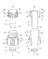
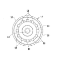
従来、この種のボトルキャップとして、例えば特許文献1(実公昭44−12957号公報)及び特許文献2(特許第3281730号公報)に記載のものが知られているが、本発明者は、これらによる問題点を解決するボトルキャップとして、図1〜図4に示すようなものを先に提案し、特許出願(特願2002−272185)するとともに、製品化している。図1及び図2はその組み立て前の状態、図3は組み立てた状態、図4はボトルにセットした状態をそれぞれ示す。 Conventionally, as this kind of bottle cap, for example, those described in Patent Document 1 (Japanese Utility Model Publication No. 44-12957) and Patent Document 2 (Japanese Patent No. 3281730) are known. As a bottle cap that solves the problem caused by the above, a bottle cap as shown in FIGS. 1 to 4 has been proposed first, and a patent application (Japanese Patent Application No. 2002-272185) has been made and commercialized. 1 and 2 show the state before the assembly, FIG. 3 shows the assembled state, and FIG. 4 shows the state set in the bottle.
このボトルキャップは、それぞれ樹脂成型された親キャップ1と子キャップ2と底蓋3とからなる。
The bottle cap includes a
親キャップ1は、ペットボトル等のボトル50(図4)の口部50aに被せるキャップ本体5に、上下両端が開口した外筒6を一体に設けている。外筒6は、キャップ本体5の頂部5aを上下に一体に貫通しており、頂部5aより上側に突出した上部は、上端が開口する口部6aとなり、また頂部5aより下側に突出した下部は、キャップ本体5の胴部5bとの間に隙間を形成しながらその下端よりも下方に垂下して下端が開口する垂下筒部6bとなっている。この垂下筒部6bは、頂部5aの近くで段差をなして細くなってから、下端開口に向かって徐々に先細となっている。垂下筒部6bの内周面の中途には、肉厚を僅かに厚くする微小な段部6cが形成されている。
The
キャップ本体5の胴部5bの内周面には、ボトル50の口部50aの雄ネジ50bと螺合する雌ネジ5cが形成され、また外筒6の口部6aの外周面には雄ネジ6dが形成されている。胴部5bの外周面には、指を掛けて開ける際の滑り止め用ローレット5dが刻設されている。
A
子キャップ2は、原料及び圧力気体充填部(カプセル)となる内筒9を、キャップ本体8の頂部8aの下面から一体に突設するとともに、この内筒9の外周の至近位置において、肉薄の短い密閉リング10を一体に突設している。内筒9は、キャップ本体8の胴部8bとの間に隙間を形成しながらそれよりもはるかに長く突出している。内筒9は、外筒6よりも径がやや小さく、外筒6との間に僅かな隙間を形成して挿入できるようになっているが、長さは外筒6よりも若干長くなっている。内筒9は、内径については上端から下端まで同じであるが、外径は、内筒9の肉厚を徐々に薄くするように上端から下端に向かって徐々に小さくなり、下端縁を外側に膨らむ突縁9eとしている。また、内筒9の外周面には、肉厚を僅かに薄くする微小な段部9cが形成されている。
The
子キャップ2の胴部8bの環状の下周縁部分8cは、全周にわたる細い切り込み8dによりその上側の部分と分離可能になっている。この切り込み8dより上側において、胴部8bの内周面には、外筒6の口部6aの雄ネジ6dと螺合する雌ネジ8eが形成されている。図3に示すように、この雌ネジ8eを雄ネジ6cに螺合させ、更に環状の下周縁部分8cが雄ネジ6dの終端を強制的に越えるところまで子キャップ2を外筒6の口部6aに被せると、口部6aが気密かつ液密に封止される。このとき、子キャップ2は、その環状の下周縁部分8cが口部6aに対し回転不能に固定され、また内筒9の下端部が、外筒6の垂下筒部6bの下端開口から突出し、内筒9の外周面中途の微小な段部9cと外筒6の内周面中途の微小な段部6cとが、近接して上下に対向する。更に、密閉リング10が外筒6の口部6a内に圧入するとともに、子キャップ2の頂部8aが外筒6の上端に圧接し、密閉リング10が子キャップ2の胴部8bの角部とで外筒6の口部6aを内外から挟持する状態となる。胴部8bの外周面には、指を掛けて開ける際の滑り止め用ローレット8fが刻設され、また頂部8aの上面には、開ける方向を指示する矢印8gが浮き出し形成されている。
An annular lower
底蓋3は、上面が凸面、下面が凹面となる押込部3aと、該押込部3aの周縁とで断面逆Ω状の環状凹溝3bを形成する環状凹部3cと、押込部3aの凹面となっている下面の中央から下向きに突出する突起3dとを一体成型している。内筒9の下端部を環状凹溝3b内に強制的に嵌め込むとともに、押込部3aを内筒9内に押し込むことにより、底蓋3は、図4に示すように圧力気体(不活性ガス)と原料11を充填した内筒9の下端開口を気密かつ液密に封止する。
The
このようなボトルキャップにおいて、子キャップ2を開く方向に回して内筒9を上昇させていくと、底蓋3の環状凹部3cの上縁が外筒6の下端縁に当接して底蓋3はそれ以上の上昇を拘束されるため、内筒6の下端の突縁9eと底蓋3の環状凹部3cとの嵌合が外れ、更に上昇していく内筒9から底蓋3が脱落する。これが脱落すると、内筒9内の原料11が圧力気体と共に一気に噴出される。底蓋3はボトル内の液中に沈降する。
In such a bottle cap, when the
しかし、これによると次のような問題点があった。
(1)親キャップ1と子キャップ2と底蓋3との3つの部品からなり、特に親キャップ1は複雑な構造であるため、コストが高くなるとともに、このボトルキャップをボトル口部に自動的に装着するキャップ自動装着装置の構造及び動作も複雑になる。
However, according to this, there were the following problems.
(1) Consists of three parts, a
(2)親キャップ1と子キャップ2とが、ボトル50の口部50aの外側で上下2段に重なった状態となるので、キャップ全体の高さが通常のキャップの2倍程度と高くなり、それだけ支障も多くなる。
(2) Since the
(3)子キャップ2の開栓により底蓋3が内筒9から脱落した後、通常は子キャップ2だけを親キャップ1から外し、親キャップ1は、底蓋3を誤飲しないようにボトル50の口部50aに残したままにして飲用するが、そのようにして飲用するように注意書きしてあっても、親キャップ1を悪戯によりボトルの口部から無理矢理外し、親キャップ1が外れたボトルの口部を口に含んで飲用して、底蓋3を誤飲したという例があった。
(3) After the
(4)子キャップ2と底蓋3において、前者の内筒9の下端の膨らんだ突縁9eと、後者の環状凹部3cの断面逆Ω状の環状凹溝3bとを嵌合させることで、内筒9の下端開口に対する底蓋3のシール性を高めようとしたが、圧力気体が封入された内筒6の気密性を確保するには充分ではなかった。
(4) In the
(5)親キャップ1の外筒6の一部、つまり垂下筒部6bは、子キャップ2の開栓後もボトルの口部中に突入したままとなり、その突入部分がボトルの口部の開口からの液流出を妨げることから、少量ではあるが飲み残しが生じる問題があった。
(5) A part of the
(6)子キャップ2は、その胴部8bに全周にわたる細い切り込み8dを形成することにより、この切り込み8dより上側の部分が下側の環状の下周縁部分8cから分離し、環状の下周縁部分8cがボトルの口部に残るようになっているが、その分離に大きな捻り力を要するために、親キャップ1まで回って親キャップ1もボトルの口部から外れてしまう恐れがあった。
本発明の第1の課題は、上記従来例における親キャップを省略しても同様の作用、つまり開栓操作に伴い原料収容部の底蓋を分離させて原料をボトル内に放出することができ、コストを低減できるとともに、ボトルキャップをボトル口部に自動的に装着するキャップ自動装着装置の構造及び動作も単純となり、かつ底蓋の誤飲を簡単な構造で防止でき、しかも親キャップの外筒に基づく飲み残しも生じないボトルキャップを提供することにある。 The first problem of the present invention is that even if the parent cap in the above-described conventional example is omitted, the same action, that is, the raw material can be discharged into the bottle by separating the bottom cover of the raw material container in accordance with the opening operation. In addition to reducing the cost, the structure and operation of the automatic cap mounting device that automatically mounts the bottle cap on the bottle mouth can be simplified, and accidental swallowing of the bottom lid can be prevented with a simple structure. An object of the present invention is to provide a bottle cap that does not cause leftovers based on a cylinder.
本発明の第2の課題は、底蓋のシール性を向上させ、原料収容部に圧力気体が封入されていても、その気密性を充分に確保できるようにすることにある。 The second problem of the present invention is to improve the sealing performance of the bottom lid so that the airtightness can be sufficiently ensured even when the pressure gas is sealed in the raw material container.
本発明の第1の形態のボトルキャップは、ボトルの口部の外周のネジに螺合するネジを内周に形成した外筒部と、ボトルの口部の開口を封止する天井部と、該天井部から垂下してボトルの口部内に挿入し、原料収納部となる内筒部とを有するキャップ本体に対して、その内筒部の下端を閉塞する底蓋部が該内筒部と一体成形され、これら内筒部と底蓋部との間に切り込みが形成されている。
そして、キャップ本体を封止方向に回転して内筒部をボトルの口部内に挿入するときは、底蓋部の一部がボトル内の喉部を越えたところで該喉部と係合し、キャップ本体を開封方向に回転して内筒部をボトルの口部から抜出していくときは、切り込みにより底蓋部の少なくとも一部分が内筒部の下端から分離して内筒部の下端が開口することにより、内筒部内の原料がボトル内に放出される。
The bottle cap according to the first aspect of the present invention includes an outer cylinder portion formed on the inner periphery with a screw that is screwed to a screw on the outer periphery of the mouth portion of the bottle, a ceiling portion that seals the opening of the mouth portion of the bottle, A bottom lid portion that closes the lower end of the inner cylinder portion with respect to the cap body having an inner cylinder portion that is suspended from the ceiling portion and inserted into the mouth portion of the bottle and serves as a raw material storage portion, It is integrally formed, and a cut is formed between the inner cylinder part and the bottom cover part.
And when rotating the cap body in the sealing direction and inserting the inner cylinder part into the mouth part of the bottle, when the part of the bottom cover part exceeds the throat part in the bottle, the throat part is engaged, When rotating the cap body in the opening direction and pulling out the inner cylinder part from the mouth part of the bottle, at least a part of the bottom lid part is separated from the lower end of the inner cylinder part by cutting, and the lower end of the inner cylinder part opens. Thereby, the raw material in an inner cylinder part is discharge | released in a bottle.
本発明の第2の形態のボトルキャップは、ボトルの口部の外周のネジに螺合するネジを内周に形成した外筒部と、ボトルの口部の開口を封止する天井部と、該天井部から垂下してボトルの口部内に挿入し、原料収納部となる内筒部とを有するキャップ本体に対して、その内筒部の下端を閉塞する底蓋部が、該内筒部と異なる樹脂にて分離可能に溶着成形されている。
そして、キャップ本体を封止方向に回転して内筒部をボトルの口部内に挿入するときは、底蓋部の一部がボトル内の喉部を越えたところで該喉部と係合し、キャップ本体を開封方向に回転して内筒部をボトルの口部から抜出していくときは、底蓋部がボトル内の喉部にて上昇を規制され、底蓋部の少なくとも一部分が内筒部の下端から分離して内筒部の下端が開口することにより、内筒部内の原料がボトル内に放出される。
The bottle cap according to the second aspect of the present invention includes an outer cylinder portion formed on the inner periphery with a screw that engages with an outer peripheral screw of the bottle mouth portion, a ceiling portion that seals the opening of the mouth portion of the bottle, A bottom lid portion that closes the lower end of the inner cylinder portion with respect to the cap body having the inner cylinder portion that hangs down from the ceiling portion and is inserted into the mouth portion of the bottle and serves as a raw material storage portion, It is weld-molded so as to be separable with a different resin.
And when rotating the cap body in the sealing direction and inserting the inner cylinder part into the mouth part of the bottle, when the part of the bottom cover part exceeds the throat part in the bottle, the throat part is engaged, When rotating the cap body in the opening direction and pulling out the inner cylinder part from the mouth part of the bottle, the bottom lid part is restricted from rising at the throat part in the bottle, and at least a part of the bottom lid part is the inner cylinder part When the lower end of the inner cylinder part is opened from the lower end of the tube, the raw material in the inner cylinder part is discharged into the bottle.
第1の形態及び第2の形態のボトルキャップの場合、底蓋部の外周に弾性変形可能な底蓋開封部を突設し、キャップ本体を封止方向に回転して内筒部をボトルの口部内に挿入していくときは、この底蓋開封部が、ボトルの口部により閉じられてボトル内の喉部を越えたところで開いた状態に復元して該喉部と係合し、キャップ本体を開封方向に回転して内筒部をボトルの口部から抜出していくときは、開いた状態の底蓋開封部が、ボトル内の喉部にて上昇を規制されて底蓋部の少なくとも一部分が内筒部の下端から分離する構造にすることができる。 In the case of the bottle caps of the first form and the second form, a bottom cover opening part that can be elastically deformed protrudes from the outer periphery of the bottom cover part, the cap body is rotated in the sealing direction, and the inner cylinder part is When inserting into the mouth part, the bottom lid opening part is closed by the mouth part of the bottle and restored to the open state beyond the throat part in the bottle, and is engaged with the throat part, When rotating the main body in the opening direction and pulling out the inner cylinder part from the mouth part of the bottle, the bottom cover opening part in the opened state is restricted from rising at the throat part in the bottle, and at least the bottom cover part It can be made the structure which a part isolate | separates from the lower end of an inner cylinder part.
又は、ボトル内の喉部と底蓋部の外周とに、互いに係合してキャップ本体の開封時に底蓋部の上昇を規制する係合突部を形成すれば、上記のような底蓋開封部を省略できる。 Alternatively, if an engaging protrusion that engages with each other and restricts the rise of the bottom lid when the cap body is opened is formed on the throat of the bottle and the outer periphery of the bottom lid, the bottom lid is opened as described above. The part can be omitted.
キャップ本体の天井部には、内筒部に対する原料入口が形成され、この原料入口は上蓋で密閉される。上蓋は、キャップ本体と別体にすることができるが、弾性変形可能なヒンジ部によりキャップ本体の天井部と一体に連続させて、キャップ本体と一体成形すれば、本ボトルキャップは全一体の単一部品となる。上蓋の上面は、その周囲の天井部上面と共に、貼付したシート材にて覆うと良い。 A raw material inlet for the inner tube portion is formed in the ceiling portion of the cap body, and this raw material inlet is sealed with an upper lid. The top lid can be separated from the cap body, but if the bottle cap is integrally formed with the cap body by an elastically deformable hinge, it can be integrated with the cap body. It becomes one part. The upper surface of the upper lid may be covered with the attached sheet material together with the upper surface of the surrounding ceiling.
本発明の第3の形態のボトルキャップは、キャップ本体と底蓋とからなる。
キャップ本体は、ボトルの口部の外周のネジに螺合するネジを内周に形成した外筒部と、ボトルの口部の開口を封止する天井部と、該天井部から垂下してボトルの口部内に挿入し、原料収納部となる内筒部とを有する。
底蓋は、キャップ本体の内筒部の下端開口を着脱自在に封止するため、内筒部の下端部を圧入させることができる環状凹部を周縁に一体に形成している。
そして、キャップ本体を封止方向に回転して内筒部をボトルの口部内に挿入するときは、底蓋の一部がボトル内の喉部を越えたところで該喉部と係合し、キャップ本体を開封方向に回転して内筒部をボトルの口部から抜出していくときは、底蓋がボトル内の喉部にて上昇を規制されて内筒部の下端から分離し、内筒部の下端が開口することにより、内筒部内の原料がボトル内に放出される。
The bottle cap of the 3rd form of this invention consists of a cap main body and a bottom cover.
The cap body includes an outer tube portion formed on the inner periphery with a screw that engages with an outer peripheral screw of the bottle mouth portion, a ceiling portion that seals the opening of the bottle mouth portion, and a bottle that hangs down from the ceiling portion. And an inner cylinder part serving as a raw material storage part.
In order to detachably seal the lower end opening of the inner cylinder part of the cap main body, the bottom cover is integrally formed with an annular concave part on the periphery, which can press-fit the lower end part of the inner cylinder part.
When the cap body is rotated in the sealing direction and the inner cylinder portion is inserted into the mouth portion of the bottle, the cap portion engages with the throat portion when the bottom lid partly exceeds the throat portion in the bottle. When rotating the main body in the opening direction and pulling out the inner cylinder part from the mouth part of the bottle, the bottom lid is restricted from rising at the throat part in the bottle and separated from the lower end of the inner cylinder part. By opening the lower end of the material, the raw material in the inner cylinder part is discharged into the bottle.
第3の形態のボトルキャップの場合、底蓋の外周に弾性変形可能な底蓋開封部を突設し、キャップ本体を封止方向に回転して内筒部をボトルの口部内に挿入していくときは、底蓋開封部が、ボトルの口部により閉じられてボトル内の喉部を越えたところで開いた状態に復元して該喉部と係合し、キャップ本体を開封方向に回転して内筒部をボトルの口部から抜出していくときは、開いた状態の底蓋開封部が、ボトル内の喉部にて上昇を規制されて底蓋が内筒部の下端から分離する構造にすることができる。 In the case of the bottle cap of the third form, a bottom lid opening portion that can be elastically deformed is projected on the outer periphery of the bottom lid, the cap body is rotated in the sealing direction, and the inner cylinder portion is inserted into the mouth portion of the bottle. When opening, the bottom lid opening part is closed by the mouth of the bottle and restored to the open state beyond the throat part in the bottle and engaged with the throat part, and the cap body is rotated in the opening direction. When the inner cylinder part is pulled out from the mouth part of the bottle, the bottom lid opening part in the open state is restricted from rising at the throat part in the bottle and the bottom lid is separated from the lower end of the inner cylinder part Can be.
第1、第2及び第3の形態のいずれの場合も、底蓋開封部の具体的構造として、環状に突出形成され、その環状の外径を弾性変形により変えることで開閉する形態、更には、下端に向かって突出高さが低くなる多数の歯部を突出形成した形態がよい。又は、分割して突出形成された複数個の爪部で構成され、これらが弾性変形することで開閉する形態でもよい。 In any case of the first, second and third modes, the concrete structure of the bottom lid opening portion is formed to project in an annular shape and open and close by changing its outer diameter by elastic deformation, A form in which a large number of tooth portions whose projecting height decreases toward the lower end is formed in a projecting manner is preferable. Alternatively, it may be configured by a plurality of claw portions that are divided and protruded, and these may be opened and closed by elastic deformation.
ボトル内の喉部に、底蓋開封部と係合する突部を形成すれば、底蓋開封部による底蓋の脱落を確実に行える。 If a protrusion that engages with the bottom lid opening portion is formed in the throat of the bottle, the bottom lid can be reliably removed by the bottom lid opening portion.
第3の形態の場合、上記第2の課題を達成するため、底蓋の環状凹部の内面には、該環状凹部よりも軟質な材質のパッキンが同時成形により一体的に設けられている。このパッキンは、その一部分を環状凹部の内面より突出させて環状凹部に埋設するとよい。 In the case of the third embodiment, in order to achieve the second problem, a packing made of a softer material than the annular recess is integrally provided on the inner surface of the annular recess of the bottom cover by simultaneous molding. The packing may be embedded in the annular recess with a part thereof protruding from the inner surface of the annular recess.
本発明の第1及び第2の形態では、キャップ本体の内筒部に下端に底蓋部を一体的に成形しており、また第3の形態では、キャップ本体と底蓋との2つの部品からなるので、図1ないし図4に示した従来例における親キャップを省略でき、しかも底蓋の一部又はそれに設けた底蓋開封部をボトル内部の喉部に係合させることで、キャップ本体の開封操作に伴う底蓋の分離を行えるので、従来に比べ構造が格段に単純になり、コストを低減できるとともに、ボトルキャップをボトル口部に自動的に装着するキャップ自動装着装置の構造及び動作も単純になる。また、底蓋は、分離した後もそれ自体に設けた係合突部又は底蓋開封部により、ボトル口部を通り抜けてボトル外へ抜け出ることはないので、底蓋を誤飲するようなことは起きない。更に、キャップ本体をボトル口部から外すと、原料収納部である内筒部もこれと一体に抜け出すので、従来のような飲み残しは生じない。 In the first and second embodiments of the present invention, the bottom lid portion is integrally formed at the lower end of the inner cylinder portion of the cap body, and in the third embodiment, two parts of the cap body and the bottom lid are formed. 1 to 4, the main cap in the conventional example can be omitted, and the cap main body can be obtained by engaging a part of the bottom lid or the bottom lid opening provided on the bottom lid with the throat inside the bottle. Since the bottom lid can be separated with the opening operation of the bottle, the structure is significantly simpler than before, the cost can be reduced, and the structure and operation of the automatic cap mounting device that automatically mounts the bottle cap on the bottle mouth Will also be simple. In addition, the bottom lid does not pass through the bottle mouth and out of the bottle by the engaging protrusion provided on the bottom lid or the bottom lid opening portion even after being separated. Will not happen. Further, when the cap main body is removed from the bottle mouth portion, the inner cylinder portion which is the raw material storage portion is also pulled out integrally therewith, so that there is no leftover as in the conventional case.
底蓋開封部の外周面に、下端に向かって突出高さが低くなる多数の歯部を突出形成すれば、キャップ本体を封止方向に回転して内筒部をボトルの口部内に挿入していくときに、底蓋開封部をスムーズに閉じることができ、またキャップ本体を開封方向に回転して内筒部をボトルの口部から抜出していくときは、多数の歯部の上端をボトル内の喉部に係合させて底蓋の分離を確実に行える。 If a large number of teeth are formed on the outer peripheral surface of the bottom lid opening part, the protrusion height decreases toward the lower end, the cap body is rotated in the sealing direction and the inner cylinder part is inserted into the mouth of the bottle. When opening, the bottom lid opening part can be closed smoothly, and when rotating the cap body in the opening direction and pulling out the inner cylinder part from the mouth part of the bottle, the upper ends of many tooth parts are The bottom lid can be reliably separated by engaging with the inner throat.
第1の形態の場合、キャップ本体の内筒部の下端に底蓋部を一体成形して、切り込みにより内筒部の下端から底蓋部の少なくとも一部分が分離する構造であるため、内筒部と底蓋との間のシール上の問題は全く生じない。しかも、成形コストを大幅に低減できる。 In the case of the first embodiment, since the bottom lid portion is integrally formed at the lower end of the inner cylinder portion of the cap body, and at least a part of the bottom lid portion is separated from the lower end of the inner cylinder portion by cutting, the inner cylinder portion There is no sealing problem between the base and the bottom lid. In addition, the molding cost can be greatly reduced.
第2の形態の場合、キャップ本体の内筒部の下端に、内筒部と異なる樹脂にて分離可能に溶着成形(いわゆる異材同時成形)しているため、内筒部と底蓋との間のシール上の問題は全く生じなく、しかも成形コストを大幅に低減できる。 In the case of the second embodiment, the lower end of the inner cylinder part of the cap body is weld-molded so as to be separable with a resin different from the inner cylinder part (so-called simultaneous molding of different materials), so between the inner cylinder part and the bottom lid The sealing problem does not occur at all, and the molding cost can be greatly reduced.
また、第1及び第2の形態の場合、キャップ本体の天井部に原料入口を形成し、これを上蓋で密閉するので、原料収納部である内筒部への原料及び圧力媒体、更には脱酸素剤等の封入が容易であるとともに、その自動封入装置が簡素でコストの低いものになる。 In the case of the first and second embodiments, the raw material inlet is formed in the ceiling portion of the cap body, and this is sealed with the upper lid, so that the raw material and pressure medium to the inner cylinder portion, which is the raw material storage portion, and further removed. The oxygen agent and the like can be easily enclosed, and the automatic enclosure device is simple and low in cost.
上蓋を弾性変形可能なヒンジ部によりキャップ本体の天井部と一体に連続させて、キャップ本体と一体成形すれば、本ボトルキャップは全一体の単一部品となるので、製造コストや部品取り扱いや原料等の自動封入の全ての面で一層有利になる。 If the upper lid is made to be integral with the ceiling of the cap body by a hinge part that can be elastically deformed, and integrally molded with the cap body, the bottle cap becomes an all-in-one single part. It becomes more advantageous in all aspects of automatic encapsulation.
更に、内筒部への封入後に、上蓋の上面を、その周囲の天井部上面と共に、貼付したシート材にて覆えば、上蓋のシール性を高めることができるとともに、上蓋で密閉してあることが外見上分からないので、飲用前の悪戯による上蓋の開栓を防止できる。 Furthermore, after sealing in the inner cylinder part, if the upper surface of the upper lid is covered with the attached sheet material together with the upper surface of the surrounding ceiling part, the sealing property of the upper lid can be improved and the upper lid is sealed with the upper lid. Since it is not apparent from the appearance, it is possible to prevent the lid from being opened due to mischief before drinking.
第3の形態の場合、底蓋の周縁の環状凹部内面に、軟質な材質のパッキンが同時成形により設けると、内筒の下端開口を底蓋で封止したとき、環状凹部に子キャップの内筒の下端部が圧入しているのに加え、更に環状凹部内においてパッキンが圧縮された状態で内筒の下端部に密着するため、シール性が非常に高く、内筒に圧力気体が封入されていても、その気密性を充分に確保できる。 In the case of the third embodiment, when a soft material packing is provided on the inner surface of the annular recess at the periphery of the bottom cover by simultaneous molding, the inner recess of the child cap is sealed in the annular recess when the lower end opening of the inner cylinder is sealed with the bottom cover. In addition to the lower end of the cylinder being press-fitted, the seal is very close because the packing is compressed in the annular recess, so the sealing performance is very high, and pressure gas is sealed in the inner cylinder. Even if it is, the airtightness can be sufficiently secured.
パッキンを環状凹部に埋設すると、パッキンと環状凹部との一体性が高まるとともに、パッキンの成形性も良くなる。 When the packing is embedded in the annular recess, the integrity of the packing and the annular recess is enhanced, and the moldability of the packing is improved.
次に、本発明の実施例を図面に基づいて詳細に説明する。 Next, embodiments of the present invention will be described in detail with reference to the drawings.
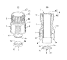
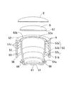
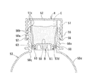
図5、図6及び図7に示すように、実施例1のボトルキャップは、樹脂成形されたキャップ本体Aと、これとは別に樹脂成形された円板状の上蓋Dの2つの部品からなる。また、必要に応じて上蓋D上にシート材Eを貼付する。 As shown in FIGS. 5, 6, and 7, the bottle cap according to the first embodiment is composed of two parts: a cap body A that is resin-molded and a disc-shaped upper lid D that is resin-molded separately. . Moreover, the sheet material E is affixed on the upper cover D as needed.
キャップ本体Aは、外筒部51と、円形の原料投入口52aを有する天井部52と、該天井部52から垂下する内筒部53と、その下端の底蓋部54とを一体成形したものである。外筒部51の内周面には、図8及び図9に示すペットボトル等のボトル50の口部50aの外周面に設けられたネジ50bと螺合するネジ51cが形成されている。また、外筒部51の下周縁部に、全周にわたる細い切り込み55を形成することにより、この切り込み55よりも上側の部分が、下側の環状の下周縁部分56から強制的に分離できるようになっている。外筒部51の切り込み55から下の下周縁部分56の内周面は斜面になっているとともに、その上側に環状段部51bが形成されている。外筒部51の外周面には、指を掛けて開ける際の滑り止め用ローレット(縦筋)51aが切り込み55よりも上側部分に刻設されている。
The cap body A is formed by integrally molding an
内筒部53は、原料及び圧力気体充填部(カプセル)となるもので、天井部52の原料投入口52aの周縁から、その開口周縁に段部52bを形成して一体に垂設され、ボトル口部50a中からボトル内の喉部50cも越えてボトル胴部50d内まで突入する長さになっている。内筒部53の上側部分53aは、その外周面がボトル口部50aの内周面に密着する大きさであるが、中間部分53bは下方に向かって従いに細くなり、下側部分53cは、ボトル口部50aの内周面及びボトル内の喉部50cとの間に間隙を形成する大きさになっている。
The
底蓋部54は、内筒部53の下端を閉塞するように内筒部53と一体になっているが、外周面に形成された切り込み54により、内筒部53から分離可能になっている。底蓋部54の外周面には、バネ性を有する複数個の爪部66が斜め上向きにかつ全体として放射状に一体に突設されている。これらの爪部66は、後述するように、底蓋部54を切り込み54において内筒部53から分離させる底蓋開封部として機能する。底蓋部54の凹面となっている下面の中央には、下向きに突出する円錐台形の突起61が一体に形成されている。
The
上蓋Dは円板状で、その下面の周縁に段部67を形成している。この上蓋Dは、原料Cを圧力気体と共に内筒部53内に入れて原料投入口52aを密閉するもので、その際、上蓋Dの段部67と原料投入口52aの開口周縁の段部52bとを嵌合させて、その嵌合部分を接着剤(例えば、ホットメルト)等で接着する。そして、その上から、シート材Eを貼付(例えば、紙製シールを貼付)して、上蓋Dの上面を、その周囲の天井部上面と共に覆う。このようにすると、上蓋Dと原料投入口52aとの間のシール性を高めることができるとともに、上蓋Dで密閉してあることを隠すことができる。
The upper lid D is disk-shaped and has a stepped
内筒部53内に収納する原料Cとしては、緑茶、コーヒー、紅茶、濃縮ミネラル、海洋深層水抽出ミネラル、健康食品、薬剤、濃縮果汁、乳製品、アルコール、濃縮野菜、スープ原料、ビタミン類、糖類、薬草類、発酵菌などを、粉末や顆粒や錠剤や液体としたものが挙げられる。また、圧力気体としては、原料Cの品質を安全に維持できる不活性ガスが良く、例えば窒素、ヘリウム、アルゴン、二酸化炭素、亜酸化窒素又はこれらの混合ガスが挙げられる。更に、脱酸素剤等を封入することもできる。
The raw material C stored in the
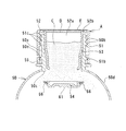
このようにした実施例1のボトルキャップをボトル50の口部50aに装着するには、図8に示すように、底蓋部54を先にしてこれをボトル口部50a内に押し込んで内筒部53をボトル口部50a内に挿入し、キャップ本体Aを封止方向に回していく。底蓋部54をボトル口部50a内に押し込んでいく際、放射状の爪部66が斜め上向きに傾斜しているので、スムーズに押し込みながら、全爪部66を無理なく弾性変形させてすぼんだ状態とし、ボトル口部50aの内周面に爪部64を摺接させながら、内筒部53をボトル口部50a内に挿入できる。
In order to attach the bottle cap of Example 1 thus configured to the
そこで、キャップ本体Aを封止方向に回しながら、その外筒部51のネジ51cをボトル口部50aのネジ50bに螺合させて、図9に示すように外筒部51の内周面の環状段部51bが、ボトル口部50aの外周面の環状凸部50eを越えるところまで強制的に螺進させる。このとき、外筒部51の下周縁部分56の内周面は斜面になっているため、環状凸部50eをスムーズに乗り越え、環状段部51bが環状凸部50eの平らな下面に係合する。
Therefore, while turning the cap main body A in the sealing direction, the
一方、ボトル口部50a内では、内筒部53がボトル胴部50d内まで突入する長さになっているので、底蓋部54がボトル内の喉部50cを越え、その全爪部66が開いた状態に復元して喉部50cの下面に係合する。
このような状態となってボトル口部50aは封止される。
On the other hand, in the
In this state, the
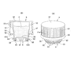
このような封止状態でキャップ本体Aを開封方向に回すと、図9に示すように、外筒部51の切り込み55よりも上側の部分は上昇可能であるが、切り込み55よりも下の下周縁部分56は、その環状段部51bが環状凸部50eの下面に係合しているため、上昇することができず、図10に示すように切り込み55において上側の部分から分離して残る。
When the cap body A is rotated in the opening direction in such a sealed state, as shown in FIG. 9, the portion above the
従って、キャップ本体Aは、このような分離を強制的に生じさせるほどの力を加えないと、回すことができないので、封止状態を確実に保持できる。 Therefore, since the cap body A cannot be turned unless a force is applied to force such separation, the sealed state can be reliably maintained.
一方、ボトル口部50a内では、キャップ本体Aを開封方向に回すと、内筒部53が回転しながら上昇するのに対し、底蓋部54は、その全爪部66が開いた状態で喉部50cの下面に係合しているため、上昇することができず、更に上昇していく内筒部53に対して底蓋部54が図10に示すように切り込み54aで分離して脱落する。これが脱落すると、内筒部53内の原料Cが圧力気体と共に一気に噴出され、底蓋部54はボトル50内の液中に沈降する。底蓋部54の下面に突起61があるため、大きく揺れながら沈降することはない。
On the other hand, in the
脱落した底蓋部54は、開いた状態に復元している全爪部66の放射外径がボトル口部50aの内径よりも大きいので、ボトル口部50aを通り抜けてボトル外へ抜け出ることはない。
The
なお、切り込み54aを全周ではなく、一部分を残して形成し、そこだけは底蓋部54が内筒部53の下端から分離しないで、底蓋部54が内筒部53の下端から脱落することなく垂下した状態で内筒部53の下端が開口するようにしてもよい。
The
図11は実施例1の変形例で、爪部66の先端を球状としたものである。このようにすると、ボトル口部50aへの挿入を、その内周面を傷つけることなく、よりスムーズに行える。
FIG. 11 shows a modification of the first embodiment, in which the
次に、実施例2について説明する。
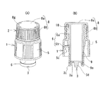
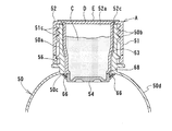
図12及び図13に示すように、実施例2のボトルキャップは、樹脂成形されたキャップ本体Aと、これとは別に樹脂成形された底蓋Bの2つの部品からなる。
Next, Example 2 will be described.
As shown in FIGS. 12 and 13, the bottle cap according to the second embodiment is composed of two parts, a cap body A that is resin-molded and a bottom lid B that is resin-molded separately.
キャップ本体Aは、外筒部51と、天井部52と、該天井部52から垂下する内筒部53とを一体成形したものである。外筒部51の内周面には、図14及び図15に示すペットボトル等のボトル50の口部50aの外周面に設けられたネジ50bと螺合するネジ51cが形成されている。また、外筒部51の下周縁部に、全周にわたる細い切り込み55を形成することにより、この切り込み55よりも上側の部分が、下側の環状の下周縁部分56から強制的に分離できるようになっている。この下周縁部分56の内周面には、バネ性を有する内側環状突部57が全周に突出形成されているとともに、この内側環状突部57の内周面には、下端に向かって突出高さが低くなる三角形状の多数の歯部57aが、所定の間隔で全周にわたり波状に突出形成されている。外筒部51の外周面には、指を掛けて開ける際の滑り止め用ローレット(縦筋)51aが切り込み55よりも上側部分に刻設されている。
The cap body A is formed by integrally forming an
内筒部53は、天井部52の下面から一体に垂設され、ボトル口部50a中からボトル内の喉部50cも越えてボトル胴部50d内まで突入する長さになっている。内筒部53の上側部分53aは、その外周面がボトル口部50aの内周面に密着する大きさであるが、中間部分53bは下方に向かって従いに細くなり、下側部分53cは、ボトル口部50aの内周面及びボトル内の喉部50cとの間に間隙を形成する大きさになっている。また、内筒部53の下端縁は外側に膨らむ突縁53dとなっている。
The
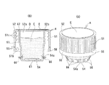
底蓋Bは、上面が凸面、下面が凹面となる押込部58と、この押込部58の周縁とで断面逆Ω状の環状凹溝59を形成する環状凹部60と、押込部58の凹面となっている下面の中央から下向きに突出する円錐台形の突起61と、環状凹部60の外面から斜め上向きに突出する環状の底蓋開封部62とを一体成形している。
The bottom cover B includes a
底蓋Bの環状凹部60内には、該環状凹部60よりも軟質な材質、例えばシリコンゴムやポリプロピレン等による環状のパッキン63が、環状凹部60との同時成形により環状凹部60の内面に一体的に設けられている。このパッキン63は、具体的には、その一部分を環状凹部60の内面より突出させて環状凹部60の底部に埋設され、環状凹部60と一体化されている。
In the
底蓋Bの底蓋開封部62は、その付け根部分、つまり環状凹部60との間に形成された窪み64によってバネ性を与えられ、環状凹部60に向かって開閉する(外向きに拡がり、内向きにすぼまる)ように弾性変形可能となっており、開いた通常の状態では、底蓋開封部62の外径はボトル口部50aの内径よりも大きい。底蓋開封部62の外周面には、下端に向かって突出高さが低くなる三角形状の多数の歯部65が、所定の間隔で全周にわたり波状に突出形成されている。
The bottom
このような構成とした実施例2は次のような組み立て状態となる。
図12に示すように、底蓋Bの環状凹部60の断面逆Ω状の環状凹溝59と、キャップ本体Aの内筒部53の下端の膨らんだ突縁53dとを強制的に嵌合させ、内筒部53の下端でパッキン63の突出部分を圧縮させる。そうすると、内筒部53の下端の膨らんだ突縁53dが、パッキン63の突出部分を圧縮させたまま断面逆Ω状の環状凹溝59に圧入した状態となるので、内筒部53の下端開口に対する底蓋Bによる閉塞は、シール性が非常に高く、内筒部53に圧力気体が封入されても、その気密性を充分に確保できる。
Example 2 configured as described above is in an assembled state as follows.
As shown in FIG. 12, the annular
キャップ本体Aの内筒部53内に、原料Cを圧力気体と共に入れて、底蓋Bで上記のように封止した後、図14に示すように、この底蓋Bを先にしてこれをボトル口部50a内に押し込んで内筒部53をボトル口部50a内に挿入し、キャップ本体Aを封止方向に回していく。底蓋Bをボトル口部50a内に押し込んでいく際、底蓋開封部62の外周面の多数の歯部65が、下端に向かって突出高さが低くなっているので、スムーズに押し込みながら、底蓋開封部62を無理なく弾性変形させてすぼんだ状態(閉じた状態)とし、ボトル口部50aの内周面に歯部65を摺接させながら、底蓋Bに続いて内筒部53をボトル口部50a内に挿入できる。
After the raw material C is put together with the pressure gas in the inner
キャップ本体Aを封止方向に回しながら、その外筒部51のネジ51cをボトル口部50aのネジ50bに螺合させて、図15に示すように外筒部51の内側環状突部57が、ボトル口部50aの外周面の環状凸部50eを越えるところまで螺進させる。このとき、外筒部51の下周縁部分56の内周面には、下端に向かって突出高さが低くなる多数の歯部57aが形成されているとともに、環状凸部50eの上面が斜面になっているため、これらの歯部57cは環状凸部50eをスムーズに乗り越え、内側環状突部57が環状凸部50eの平らな下面に係合する。
While turning the cap main body A in the sealing direction, the
一方、ボトル口部50a内では、図15に示すように、内筒部53がボトル胴部50d内まで突入する長さになっているので、底蓋Bがボトル内の喉部50cを越え、その底蓋開封部62が開いた状態に復元して喉部50cの下面に係合する。
このような状態となってボトル口部50aは封止される。
On the other hand, in the
In this state, the
このような封止状態でキャップ本体Aを開封方向に回すと、図16に示すように、外筒部51の切り込み55よりも上側の部分は上昇可能であるが、切り込み55よりも下の下周縁部分56は、その内側環状突部57が環状凸部50eの下面に係合しているため、上昇することができず、切り込み55において上側の部分から分離して残る。
When the cap body A is rotated in the opening direction in such a sealed state, as shown in FIG. 16, the upper part of the
従って、キャップ本体Aは、このような分離を強制的に生じさせるほどの力を加えないと、回すことができないので、封止状態を確実に保持できる。 Therefore, since the cap body A cannot be turned unless a force is applied to force such separation, the sealed state can be reliably maintained.
一方、ボトル口部50a内では、キャップ本体Aを開封方向に回すと、内筒部53が回転しながら上昇するのに対し、底蓋Bは、その底蓋開封部62が開いた状態で喉部50cの下面に係合しているため、上昇することができず、更に上昇していく内筒部53から図16に示すように底蓋Bが外れて脱落する。これが脱落すると、内筒部53内の原料Cが圧力気体と共に一気に噴出され、底蓋Bはボトル50内の液中に沈降する。底蓋Bの下面に突起61があるため、大きく揺れながら沈降することはない。
On the other hand, in the
脱落した底蓋Bは、開いた状態に復元している底蓋開封部62の外径がボトル口部50aの内径よりも大きいので、ボトル口部50aを通り抜けてボトル外へ抜け出ることはない。
Since the bottom cover B that has fallen out has an outer diameter of the bottom
なお、図17に示すように、ボトル内の喉部50cの周縁に突部50fを形成すれば、これに底蓋Bの底蓋開封部62が係合するので底蓋Bの脱落を確実に行える。
In addition, as shown in FIG. 17, if the
また、底蓋開封部62を環状にするのではなく、図18に示すように、円周方向に分割されたバネ性を有する複数個の爪部66をもって構成してもよい。これら爪部66は、環状凹部60の外周面から斜め上向きに一体に放射状に突設されている。
Further, the bottom
更に、キャップ本体Aについては、実施例2は外筒部51の下端周縁に、多数の歯部57aを形成したバネ性を有する内側環状突部57を形成したが、図19に示すような構造にしてもよい。すなわち、外筒部51の切り込み55から下の下周縁部分56の内周面を斜面とするとともに、その上側に環状段部51bを形成し、キャップ本体Aの密封状態では、下周縁部分56がボトル口部50aの環状凸部50eを越えてこの環状凸部50eに環状段部51bが係合することで、キャップ本体Aの開封時に、切り込み55からキャップ本体Aが上下に分離するようになっている。
Further, with respect to the cap main body A, in Example 2, the inner
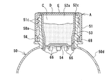
次に、図20〜図22に示す実施例3について説明する。
実施例3のボトルキャップは、樹脂成形されたキャップ本体Aと円板状の上蓋Dとを一体成形した単一部品からなり、必要に応じて上蓋D上にシート材Eを貼付する。
Next, Example 3 shown in FIGS. 20 to 22 will be described.
The bottle cap according to the third embodiment is a single part in which a resin-molded cap body A and a disc-shaped upper lid D are integrally molded, and a sheet material E is stuck on the upper lid D as necessary.
キャップ本体Aは、実施例1の場合と同様に、外筒部51と、円形の原料投入口52aを有する天井部52と、該天井部52から垂下する内筒部53と、その下端の底蓋部54とを、上蓋Dと共に一体に同時成形したものである。外筒部51の内周面には、ボトル50の口部50aの外周面に設けられたネジ50bと螺合するネジ51cが形成されている。また、外筒部51の下周縁部に、全周にわたる細い切り込み55を形成することにより、この切り込み55よりも上側の部分が、下側の環状の下周縁部分56から強制的に分離できるようになっている。外筒部51の切り込み55から下の下周縁部分56の内周面は斜面になっているとともに、その上側に環状段部51bが形成されている。外筒部51の外周面には、指を掛けて開ける際の滑り止め用ローレット(縦筋)が切り込み55よりも上側部分に刻設されている。
As in the case of the first embodiment, the cap body A includes an
内筒部53は、実施例1の場合と同様に、天井部52の原料投入口52aの周縁から、その開口周縁に段部52bを形成して一体に垂設され、ボトル口部50a中からボトル内の喉部50cも越えてボトル胴部50d内まで突入する長さになっている。内筒部53の上側部分53aは、その外周面がボトル口部50aの内周面に密着する大きさであるが、中間部分53bは下方に向かって従いに細くなり、下側部分53cは、ボトル口部50aの内周面及びボトル内の喉部50cとの間に間隙を形成する大きさになっている。
As in the case of the first embodiment, the
底蓋部54は、内筒部53の下端を閉塞するように内筒部53と一体になっているが、外周面に形成された切り込み54により、内筒部53から分離可能になっている。切り込み54は口を拡げた形状になっている。そして、この切り込み54の下側に、底蓋開封部として、肉厚を下に向かって徐々に薄くすることにより外周面を傾斜面とした係合突部54bが一体に形成されている。
The
上蓋Dは円板状で、実施例1の場合と同様に、その下面の周縁に段部67を形成しているが、キャップ本体Aの天井部52と一部分をヒンジ部52cとして一体に連続させることにより、キャップ本体Aと一体成形されている。ヒンジ部52cは、一部分に限定して形成されているため弾性変形可能で、上蓋Dは、原料投入口52aに対し開閉自在となっている。この上蓋Dも、その段部67と原料投入口52aの開口周縁の段部52bとを嵌合させて、その嵌合部分を接着剤(例えば、ホットメルト)等で接着して密閉する。そして、その上から、シート材Eを貼付して、上蓋Dの上面を、その周囲の天井部上面と共に覆う。
The upper lid D is disk-shaped and has a stepped
一方、ボトル内の喉部50cの内周面には、肉厚を下に向かって徐々に厚くすることにより内周面を傾斜面とした係合突部50gが一体に形成されている。
On the other hand, on the inner peripheral surface of the
この実施例3のボトルキャップをボトル50の口部50aに装着するには、キャップ本体Aを封止方向に回しながら、図21に示すように、その外筒部51のネジ51cをボトル口部50aのネジ50bに螺合させて、外筒部51の内周面の環状段部51bが、図22に示すように、ボトル口部50aの外周面の環状凸部50eを越えるところまで強制的に螺進させる。このとき、外筒部51の下周縁部分56の内周面は斜面になっているため、環状凸部50eをスムーズに乗り越え、環状段部51bが環状凸部50eの平らな下面に係合する。
In order to attach the bottle cap of the third embodiment to the
このとき、ボトル口部50a内では、最終近くで、底蓋部54の外周の係合突部(底蓋開封部)54bの傾斜面が、ボトル50の喉部50cの内周の係合突部50gの傾斜面を摺接しながら、この係合突部50gの傾斜面を越え、最終には、図22に示すように底蓋部54の係合突部54bが係合突部50gの下側でこれと係合するとともに、喉部50cの係合突部50gが、底蓋部54の切り込み54aの拡がっている口に少し入り込む。このような状態となってボトル口部50aは封止される。
At this time, in the
このような封止状態でキャップ本体Aを開封方向に回すと、実施例1の場合と同様に、外筒部51の切り込み55よりも上側の部分は上昇可能であるが、切り込み55よりも下の下周縁部分56は、その環状段部51bが環状凸部50eの下面に係合しているため、上昇することができず、切り込み55において上側の部分から分離して残る。
When the cap body A is rotated in the opening direction in such a sealed state, the upper part of the
一方、ボトル口部50a内では、キャップ本体Aを開封方向に回すと、内筒部53が回転しながら上昇するのに対し、底蓋部54は、その係合突部54bが喉部50cの係合突部50gの下面に係合しているため、上昇することができず、更に上昇していく内筒部53に対して底蓋部54が切り込み54aで分離して脱落する。
On the other hand, in the
脱落した底蓋部54は、その係合突部54bが喉部50cの内径よりも大きいので、ボトル口部50aを通り抜けてボトル外へ抜け出ることはない。
The
なお、実施例3の場合も、切り込み54aを全周ではなく、一部分を残して形成し、そこだけは底蓋部54が内筒部53の下端から分離しないで、底蓋部54が内筒部53の下端から脱落することなく垂下した状態で内筒部53の下端が開口するようにしてもよい。
Also in the case of the third embodiment, the
次に、図23及び図24に示す実施例4について説明する。
実施例4のボトルキャップも、樹脂成形されたキャップ本体Aと円板状の上蓋Dとを一体成形した単一部品からなり、必要に応じて上蓋D上にシート材Eを貼付する。
Next, Example 4 shown in FIGS. 23 and 24 will be described.
The bottle cap of Example 4 also consists of a single part in which a resin-molded cap body A and a disk-shaped upper lid D are integrally molded, and a sheet material E is stuck on the upper lid D as necessary.
キャップ本体Aは、実施例3の場合と同様に、外筒部51と、円形の原料投入口52aを有する天井部52と、天井部52から垂下する内筒部53と、底蓋部54とを、上蓋Dと共に一体に同時成形したものであるが、底蓋部54は、内筒部53とは異なる樹脂で同時成形(異材同時成形)されている。
As in the case of the third embodiment, the cap body A includes an
すなわち、底蓋部54は、上蓋Dを含むキャップ本体Aの成形時に、キャップ本体Aとは異なる樹脂を同じ金型に流し込んで、底蓋部54を内筒部53の下端に分離可能に溶着成形したもので、内筒部53の下端との溶着面68は、その面での底蓋部54の分離が容易になるように、梨地のような微小凹凸面になっている。
That is, when the cap body A including the upper cover D is molded, the
底蓋部54の外周面には、図5〜図10に示した実施例1の場合と同様に、底蓋開封部として、バネ性を有する複数個の爪部66が斜め上向きにかつ全体として放射状に一体に突設されている。
On the outer peripheral surface of the
このような構成にした実施例4のボトルキャップによると、実施例1の場合と同様に、キャップ本体Aを封止方向に回して底蓋部54をボトル口部50a内に押し込んで行くと、全爪部66はすぼんだ状態となってボトル口部50aの内周面に摺接し、ボトル内の喉部50cを越えたところで、全爪部66が開いた状態に復元して喉部50cの下面に係合し、ボトル口部50aが封止される。
According to the bottle cap of Example 4 having such a configuration, as in Example 1, when the cap body A is turned in the sealing direction and the
このような封止状態でキャップ本体Aを開封方向に回し、外筒部51と共に内筒部53を上昇させて行くと、底蓋部54は、その爪部66がボトル口部50aの喉部50cと係合しているため上昇できない、ここで、底蓋部54は、内筒部53の下端に分離可能に溶着成形されているため、更に上昇していく内筒部53に対してその下端の溶着面68で分離し、ボトル本体内に落下する。
When the cap main body A is rotated in the opening direction in such a sealed state and the
なお、底蓋部54が内筒部53の下端から完全に脱落分離しないで、一部分を残して分離し、その部分で底蓋部54が内筒部53の下端から垂下した状態で内筒部53の下端が開口するようにしてもよい。
In addition, the
図25及び図26は実施例4の変形例で、底蓋部54の底蓋開封部である爪部66を、底蓋部54の下面の周縁に放射状に一体に垂下形成したものである。
25 and 26 show a modification of the fourth embodiment, in which
A キャップ本体
B 底蓋
50 ボトル
50a 口部
50b ネジ
50c 喉部
50d 胴部
50e 環状凸部
50f 突部
50g 係合突部
51 外筒部
51a 滑り止め用ローレット
51b 環状段部
51c ネジ
52 天井部
52a 原料投入口
52b 段部
52c ヒンジ部
53 内筒部
53a 上側部分
53b 中間部分
53c 下側部分
53d 突縁
54 底蓋部
54a 切り込み
54b 係合突部
55 切り込み
56 下周縁部分
57 内側環状突部
57a 歯部
58 押込部
59 環状凹溝
60 環状凹部
61 突起
62 底蓋開封部
63 パッキン
64 窪み
65 歯部
66 爪部
67 段部
68 溶着面
A Cap body B Bottom cover 50
Claims (15)
キャップ本体を封止方向に回転して内筒部をボトルの口部内に挿入するときは、底蓋部の一部がボトル内の喉部を越えたところで該喉部と係合し、キャップ本体を開封方向に回転して内筒部をボトルの口部から抜出していくときは、底蓋部がボトル内の喉部にて上昇を規制され、前記切り込みにより底蓋部の少なくとも一部分が内筒部の下端から分離して内筒部の下端が開口することにより、内筒部内の原料がボトル内に放出されることを特徴とするボトルキャップ。 An outer tube part formed on the inner periphery with a screw threadedly engaged with a screw on the outer periphery of the bottle mouth part, a ceiling part for sealing the opening of the bottle mouth part, and hanging from the ceiling part into the mouth part of the bottle For a cap body having an inner cylinder part to be inserted and serving as a raw material storage part, a bottom cover part closing the lower end of the inner cylinder part is integrally formed with the inner cylinder part, and these inner cylinder part and bottom cover part A notch is formed between
When the cap body is rotated in the sealing direction and the inner cylinder part is inserted into the mouth part of the bottle, the cap body engages with the throat part when the part of the bottom cover part exceeds the throat part in the bottle. When the inner cylinder part is pulled out from the mouth part of the bottle by rotating in the opening direction, the bottom lid part is restricted from rising at the throat part in the bottle, and at least a part of the bottom lid part is regulated by the cut. A bottle cap characterized in that the raw material in the inner cylinder part is discharged into the bottle by separating from the lower end of the part and opening the lower end of the inner cylinder part.
キャップ本体を封止方向に回転して内筒部をボトルの口部内に挿入するときは、底蓋部の一部がボトル内の喉部を越えたところで該喉部と係合し、キャップ本体を開封方向に回転して内筒部をボトルの口部から抜出していくときは、底蓋部がボトル内の喉部にて上昇を規制され、底蓋部の少なくとも一部分が内筒部の下端から分離して内筒部の下端が開口することにより、内筒部内の原料がボトル内に放出されることを特徴とするボトルキャップ。 An outer tube part formed on the inner periphery with a screw threadedly engaged with a screw on the outer periphery of the bottle mouth part, a ceiling part for sealing the opening of the bottle mouth part, and hanging from the ceiling part into the mouth part of the bottle Inserted into a cap body having an inner cylinder part serving as a raw material storage part, a bottom lid part that closes the lower end of the inner cylinder part is weld-molded so as to be separable with a resin different from the inner cylinder part,
When the cap body is rotated in the sealing direction and the inner cylinder part is inserted into the mouth part of the bottle, the cap body engages with the throat part when the part of the bottom cover part exceeds the throat part in the bottle. When the inner cylinder part is pulled out from the mouth of the bottle by rotating in the opening direction, the bottom lid part is restricted from rising at the throat part in the bottle, and at least a part of the bottom lid part is the lower end of the inner cylinder part A bottle cap characterized in that the raw material in the inner cylinder part is released into the bottle when the lower end of the inner cylinder part is opened after being separated from the bottle.
キャップ本体を封止方向に回転して内筒部をボトルの口部内に挿入していくときは、底蓋開封部が、ボトルの口部により閉じられてボトル内の喉部を越えたところで開いた状態に復元して該喉部と係合し、キャップ本体を開封方向に回転して内筒部をボトルの口部から抜出していくときは、開いた状態の底蓋開封部が、ボトル内の喉部にて上昇を規制されて底蓋部の少なくとも一部分が前記切り込みにより内筒部の下端から分離することを特徴とする請求項1又は2に記載のボトルキャップ。 A bottom lid opening portion that can be elastically deformed protrudes from the bottom lid portion,
When the cap body is rotated in the sealing direction and the inner cylinder part is inserted into the mouth part of the bottle, the bottom cover opening part is closed by the mouth part of the bottle and opened beyond the throat part in the bottle. When the cap body is rotated in the opening direction and the inner cylinder portion is pulled out from the mouth of the bottle, the opened bottom lid opening portion is The bottle cap according to claim 1 or 2, wherein at least a part of the bottom lid part is separated from a lower end of the inner cylinder part by the notch by being controlled by the throat part.
キャップ本体は、ボトルの口部の外周のネジに螺合するネジを内周に形成した外筒部と、ボトルの口部の開口を封止する天井部と、該天井部から垂下してボトルの口部内に挿入し、原料収納部となる内筒部とを有し、
底蓋は、前記内筒部の下端開口を着脱自在に封止するため、内筒部の下端部を圧入させることができる環状凹部を周縁に一体に形成しており、
キャップ本体を封止方向に回転して内筒部をボトルの口部内に挿入するときは、底蓋の一部がボトル内の喉部を越えたところで該喉部と係合し、キャップ本体を開封方向に回転して内筒部をボトルの口部から抜出していくときは、底蓋がボトル内の喉部にて上昇を規制されて内筒部の下端から分離し、内筒部の下端が開口することにより、内筒部内の原料がボトル内に放出されることを特徴とするボトルキャップ。 It consists of a cap body and a bottom lid,
The cap body includes an outer tube portion formed on the inner periphery with a screw that engages with an outer peripheral screw of the bottle mouth portion, a ceiling portion that seals the opening of the bottle mouth portion, and a bottle that hangs down from the ceiling portion. And has an inner cylinder part that becomes a raw material storage part,
In order to detachably seal the lower end opening of the inner cylinder part, the bottom cover is integrally formed with an annular recess that can press-fit the lower end part of the inner cylinder part,
When the cap body is rotated in the sealing direction and the inner cylinder portion is inserted into the mouth portion of the bottle, the cap portion is engaged with the throat portion when a part of the bottom lid exceeds the throat portion in the bottle. When rotating in the opening direction and pulling out the inner cylinder part from the mouth part of the bottle, the bottom lid is restricted from rising at the throat part in the bottle and separated from the lower end of the inner cylinder part, and the lower end of the inner cylinder part The bottle cap is characterized in that the material in the inner cylinder part is released into the bottle by opening.
キャップ本体を封止方向に回転して内筒部をボトルの口部内に挿入していくときは、底蓋開封部が、ボトルの口部により閉じられてボトル内の喉部を越えたところで開いた状態に復元して該喉部と係合し、キャップ本体を開封方向に回転して内筒部をボトルの口部から抜出していくときは、開いた状態の底蓋開封部が、ボトル内の喉部にて上昇を規制されて底蓋が内筒部の下端から分離することを特徴とする請求項8に記載のボトルキャップ。 The bottom lid is provided with a bottom lid opening that can be elastically deformed,
When the cap body is rotated in the sealing direction and the inner cylinder part is inserted into the mouth part of the bottle, the bottom cover opening part is closed by the mouth part of the bottle and opened beyond the throat part in the bottle. When the cap body is rotated in the opening direction and the inner cylinder portion is pulled out from the mouth of the bottle, the opened bottom lid opening portion is The bottle cap according to claim 8, wherein the bottom lid is separated from the lower end of the inner cylindrical portion by being restricted from rising at the throat.
Priority Applications (12)
| Application Number | Priority Date | Filing Date | Title |
|---|---|---|---|
| JP2004232134A JP2005200100A (en) | 2003-11-27 | 2004-08-09 | Bottle cap |
| TW094109081A TWI344921B (en) | 2004-03-29 | 2005-03-24 | Bottle cap |
| PT05006676T PT1582331E (en) | 2004-03-29 | 2005-03-25 | Bottle cap |
| PL05006676T PL1582331T3 (en) | 2004-03-29 | 2005-03-25 | Bottle cap |
| DK05006676T DK1582331T3 (en) | 2004-03-29 | 2005-03-25 | bottle caps |
| DE602005014901T DE602005014901D1 (en) | 2004-03-29 | 2005-03-25 | bottle Cap |
| AT05006676T ATE433844T1 (en) | 2004-03-29 | 2005-03-25 | BOTTLE CAP |
| EP05006676A EP1582331B1 (en) | 2004-03-29 | 2005-03-25 | Bottle cap |
| ES05006676T ES2328703T3 (en) | 2004-03-29 | 2005-03-25 | BOTTLE PLUG. |
| KR1020050025909A KR20060044918A (en) | 2004-03-29 | 2005-03-29 | Bottle cap |
| US11/091,484 US20050211579A1 (en) | 2004-03-29 | 2005-03-29 | Bottle cap |
| HK06103916A HK1083820A1 (en) | 2004-03-29 | 2006-03-29 | Bottle cap |
Applications Claiming Priority (3)
| Application Number | Priority Date | Filing Date | Title |
|---|---|---|---|
| JP2003397804 | 2003-11-27 | ||
| JP2003423478 | 2003-12-19 | ||
| JP2004232134A JP2005200100A (en) | 2003-11-27 | 2004-08-09 | Bottle cap |
Publications (2)
| Publication Number | Publication Date |
|---|---|
| JP2005200100A true JP2005200100A (en) | 2005-07-28 |
| JP2005200100A5 JP2005200100A5 (en) | 2007-09-06 |
Family
ID=34830956
Family Applications (1)
| Application Number | Title | Priority Date | Filing Date |
|---|---|---|---|
| JP2004232134A Pending JP2005200100A (en) | 2003-11-27 | 2004-08-09 | Bottle cap |
Country Status (1)
| Country | Link |
|---|---|
| JP (1) | JP2005200100A (en) |
Cited By (5)
| Publication number | Priority date | Publication date | Assignee | Title |
|---|---|---|---|---|
| WO2009020352A1 (en) * | 2007-08-07 | 2009-02-12 | Jctech Corporation | Bottle cap |
| EP2096041A1 (en) * | 2008-02-26 | 2009-09-02 | Nestec S.A. | A closure with built-in storing compartment |
| WO2011139026A2 (en) * | 2010-05-02 | 2011-11-10 | Lee Sang Yeon | Beverage container cover for holding natural scent extracts |
| US8302795B2 (en) | 2007-07-16 | 2012-11-06 | Cedevita D.O.O. | Cap for bottles with box for powder material for preparation of beverages |
| CN105923257A (en) * | 2016-06-13 | 2016-09-07 | 蔡凤文 | Drinking water bottle cap with built-in straw |
Citations (6)
| Publication number | Priority date | Publication date | Assignee | Title |
|---|---|---|---|---|
| JPS5018844Y1 (en) * | 1969-05-24 | 1975-06-09 | ||
| JPS61172048U (en) * | 1985-04-15 | 1986-10-25 | ||
| JPH01126955U (en) * | 1988-01-26 | 1989-08-30 | ||
| JPH0891418A (en) * | 1994-09-28 | 1996-04-09 | Yoshino Kogyosho Co Ltd | Two-agent-mixing container |
| JPH09202331A (en) * | 1996-01-25 | 1997-08-05 | Akio Oyaji | Method and apparatus for packaging drink |
| JP2002249175A (en) * | 2001-02-19 | 2002-09-03 | Yakushima Hachimanju Chaen:Kk | Drinking vessel |
-
2004
- 2004-08-09 JP JP2004232134A patent/JP2005200100A/en active Pending
Patent Citations (6)
| Publication number | Priority date | Publication date | Assignee | Title |
|---|---|---|---|---|
| JPS5018844Y1 (en) * | 1969-05-24 | 1975-06-09 | ||
| JPS61172048U (en) * | 1985-04-15 | 1986-10-25 | ||
| JPH01126955U (en) * | 1988-01-26 | 1989-08-30 | ||
| JPH0891418A (en) * | 1994-09-28 | 1996-04-09 | Yoshino Kogyosho Co Ltd | Two-agent-mixing container |
| JPH09202331A (en) * | 1996-01-25 | 1997-08-05 | Akio Oyaji | Method and apparatus for packaging drink |
| JP2002249175A (en) * | 2001-02-19 | 2002-09-03 | Yakushima Hachimanju Chaen:Kk | Drinking vessel |
Cited By (7)
| Publication number | Priority date | Publication date | Assignee | Title |
|---|---|---|---|---|
| US8302795B2 (en) | 2007-07-16 | 2012-11-06 | Cedevita D.O.O. | Cap for bottles with box for powder material for preparation of beverages |
| WO2009020352A1 (en) * | 2007-08-07 | 2009-02-12 | Jctech Corporation | Bottle cap |
| EP2096041A1 (en) * | 2008-02-26 | 2009-09-02 | Nestec S.A. | A closure with built-in storing compartment |
| WO2009106489A1 (en) * | 2008-02-26 | 2009-09-03 | Nestec S.A. | A closure with built-in storing compartment |
| WO2011139026A2 (en) * | 2010-05-02 | 2011-11-10 | Lee Sang Yeon | Beverage container cover for holding natural scent extracts |
| WO2011139026A3 (en) * | 2010-05-02 | 2012-03-01 | Lee Sang Yeon | Beverage container cover for holding natural scent extracts |
| CN105923257A (en) * | 2016-06-13 | 2016-09-07 | 蔡凤文 | Drinking water bottle cap with built-in straw |
Similar Documents
| Publication | Publication Date | Title |
|---|---|---|
| EP1582331B1 (en) | Bottle cap | |
| JP2022048394A (en) | Metal container comprising closing part provided with screw | |
| JP2004075133A (en) | Vessel sealing mechanism and cap used for the mechanism | |
| CA2683924C (en) | Cap assembly having storage chamber for secondary material with movable working member | |
| CN100377973C (en) | Bottle cap | |
| JP5021023B2 (en) | Non-separating type heterogeneous substance receiving device | |
| EP1833732A1 (en) | Tamper-evident closure and bead on container neck | |
| JP4217448B2 (en) | Bottle cap | |
| CA2473290A1 (en) | Container for containing two different separate products and mixing them | |
| JP4340313B2 (en) | Bottle cap | |
| JP3130480U (en) | Bottle cap | |
| JP4160899B2 (en) | Lid assembly with valve | |
| EP1721836A1 (en) | Temper evident cap | |
| JP2005280750A5 (en) | ||
| JP2005200100A (en) | Bottle cap | |
| JP2005088997A (en) | Bottle cap | |
| JP3139281U (en) | Bottle cap | |
| JP2013129430A (en) | Pilfer-proof cap | |
| JP3140776U (en) | Bottle cap | |
| JP2005170473A (en) | Synthetic resin cap, closing device, and drink packed in container | |
| JP4518319B2 (en) | cap | |
| JP2002249175A (en) | Drinking vessel | |
| JP2020045114A (en) | Over-cap and container with over-cap | |
| JP2004299682A (en) | Plastic cap | |
| CN218259742U (en) | Instant beverage bottle cap |
Legal Events
| Date | Code | Title | Description |
|---|---|---|---|
| A521 | Written amendment |
Free format text: JAPANESE INTERMEDIATE CODE: A523 Effective date: 20070725 |
|
| A621 | Written request for application examination |
Free format text: JAPANESE INTERMEDIATE CODE: A621 Effective date: 20070725 |
|
| A521 | Written amendment |
Free format text: JAPANESE INTERMEDIATE CODE: A821 Effective date: 20080411 |
|
| RD02 | Notification of acceptance of power of attorney |
Free format text: JAPANESE INTERMEDIATE CODE: A7422 Effective date: 20080411 |
|
| RD04 | Notification of resignation of power of attorney |
Free format text: JAPANESE INTERMEDIATE CODE: A7424 Effective date: 20080415 |
|
| A521 | Written amendment |
Free format text: JAPANESE INTERMEDIATE CODE: A821 Effective date: 20090904 |
|
| RD04 | Notification of resignation of power of attorney |
Free format text: JAPANESE INTERMEDIATE CODE: A7424 Effective date: 20090904 |
|
| RD02 | Notification of acceptance of power of attorney |
Free format text: JAPANESE INTERMEDIATE CODE: A7422 Effective date: 20090916 |
|
| A131 | Notification of reasons for refusal |
Free format text: JAPANESE INTERMEDIATE CODE: A131 Effective date: 20100112 |
|
| A02 | Decision of refusal |
Free format text: JAPANESE INTERMEDIATE CODE: A02 Effective date: 20100511 |