JP2005195734A - Light-emitting control apparatus, display apparatus, display control apparatus and display control program - Google Patents
Light-emitting control apparatus, display apparatus, display control apparatus and display control program Download PDFInfo
- Publication number
- JP2005195734A JP2005195734A JP2004000206A JP2004000206A JP2005195734A JP 2005195734 A JP2005195734 A JP 2005195734A JP 2004000206 A JP2004000206 A JP 2004000206A JP 2004000206 A JP2004000206 A JP 2004000206A JP 2005195734 A JP2005195734 A JP 2005195734A
- Authority
- JP
- Japan
- Prior art keywords
- display
- moving image
- light emission
- backlight
- display device
- Prior art date
- Legal status (The legal status is an assumption and is not a legal conclusion. Google has not performed a legal analysis and makes no representation as to the accuracy of the status listed.)
- Withdrawn
Links
Images


Classifications
-
- G—PHYSICS
- G02—OPTICS
- G02F—OPTICAL DEVICES OR ARRANGEMENTS FOR THE CONTROL OF LIGHT BY MODIFICATION OF THE OPTICAL PROPERTIES OF THE MEDIA OF THE ELEMENTS INVOLVED THEREIN; NON-LINEAR OPTICS; FREQUENCY-CHANGING OF LIGHT; OPTICAL LOGIC ELEMENTS; OPTICAL ANALOGUE/DIGITAL CONVERTERS
- G02F1/00—Devices or arrangements for the control of the intensity, colour, phase, polarisation or direction of light arriving from an independent light source, e.g. switching, gating or modulating; Non-linear optics
- G02F1/01—Devices or arrangements for the control of the intensity, colour, phase, polarisation or direction of light arriving from an independent light source, e.g. switching, gating or modulating; Non-linear optics for the control of the intensity, phase, polarisation or colour
- G02F1/13—Devices or arrangements for the control of the intensity, colour, phase, polarisation or direction of light arriving from an independent light source, e.g. switching, gating or modulating; Non-linear optics for the control of the intensity, phase, polarisation or colour based on liquid crystals, e.g. single liquid crystal display cells
- G02F1/133—Constructional arrangements; Operation of liquid crystal cells; Circuit arrangements
-
- G—PHYSICS
- G09—EDUCATION; CRYPTOGRAPHY; DISPLAY; ADVERTISING; SEALS
- G09G—ARRANGEMENTS OR CIRCUITS FOR CONTROL OF INDICATING DEVICES USING STATIC MEANS TO PRESENT VARIABLE INFORMATION
- G09G3/00—Control arrangements or circuits, of interest only in connection with visual indicators other than cathode-ray tubes
- G09G3/20—Control arrangements or circuits, of interest only in connection with visual indicators other than cathode-ray tubes for presentation of an assembly of a number of characters, e.g. a page, by composing the assembly by combination of individual elements arranged in a matrix no fixed position being assigned to or needed to be assigned to the individual characters or partial characters
- G09G3/34—Control arrangements or circuits, of interest only in connection with visual indicators other than cathode-ray tubes for presentation of an assembly of a number of characters, e.g. a page, by composing the assembly by combination of individual elements arranged in a matrix no fixed position being assigned to or needed to be assigned to the individual characters or partial characters by control of light from an independent source
- G09G3/3406—Control of illumination source
- G09G3/342—Control of illumination source using several illumination sources separately controlled corresponding to different display panel areas, e.g. along one dimension such as lines
-
- G—PHYSICS
- G09—EDUCATION; CRYPTOGRAPHY; DISPLAY; ADVERTISING; SEALS
- G09G—ARRANGEMENTS OR CIRCUITS FOR CONTROL OF INDICATING DEVICES USING STATIC MEANS TO PRESENT VARIABLE INFORMATION
- G09G3/00—Control arrangements or circuits, of interest only in connection with visual indicators other than cathode-ray tubes
- G09G3/20—Control arrangements or circuits, of interest only in connection with visual indicators other than cathode-ray tubes for presentation of an assembly of a number of characters, e.g. a page, by composing the assembly by combination of individual elements arranged in a matrix no fixed position being assigned to or needed to be assigned to the individual characters or partial characters
- G09G3/2092—Details of a display terminals using a flat panel, the details relating to the control arrangement of the display terminal and to the interfaces thereto
- G09G3/2096—Details of the interface to the display terminal specific for a flat panel
-
- G—PHYSICS
- G09—EDUCATION; CRYPTOGRAPHY; DISPLAY; ADVERTISING; SEALS
- G09G—ARRANGEMENTS OR CIRCUITS FOR CONTROL OF INDICATING DEVICES USING STATIC MEANS TO PRESENT VARIABLE INFORMATION
- G09G2310/00—Command of the display device
- G09G2310/02—Addressing, scanning or driving the display screen or processing steps related thereto
- G09G2310/0237—Switching ON and OFF the backlight within one frame
-
- G—PHYSICS
- G09—EDUCATION; CRYPTOGRAPHY; DISPLAY; ADVERTISING; SEALS
- G09G—ARRANGEMENTS OR CIRCUITS FOR CONTROL OF INDICATING DEVICES USING STATIC MEANS TO PRESENT VARIABLE INFORMATION
- G09G2310/00—Command of the display device
- G09G2310/02—Addressing, scanning or driving the display screen or processing steps related thereto
- G09G2310/024—Scrolling of light from the illumination source over the display in combination with the scanning of the display screen
-
- G—PHYSICS
- G09—EDUCATION; CRYPTOGRAPHY; DISPLAY; ADVERTISING; SEALS
- G09G—ARRANGEMENTS OR CIRCUITS FOR CONTROL OF INDICATING DEVICES USING STATIC MEANS TO PRESENT VARIABLE INFORMATION
- G09G2310/00—Command of the display device
- G09G2310/04—Partial updating of the display screen
-
- G—PHYSICS
- G09—EDUCATION; CRYPTOGRAPHY; DISPLAY; ADVERTISING; SEALS
- G09G—ARRANGEMENTS OR CIRCUITS FOR CONTROL OF INDICATING DEVICES USING STATIC MEANS TO PRESENT VARIABLE INFORMATION
- G09G2320/00—Control of display operating conditions
- G09G2320/02—Improving the quality of display appearance
- G09G2320/0247—Flicker reduction other than flicker reduction circuits used for single beam cathode-ray tubes
-
- G—PHYSICS
- G09—EDUCATION; CRYPTOGRAPHY; DISPLAY; ADVERTISING; SEALS
- G09G—ARRANGEMENTS OR CIRCUITS FOR CONTROL OF INDICATING DEVICES USING STATIC MEANS TO PRESENT VARIABLE INFORMATION
- G09G2320/00—Control of display operating conditions
- G09G2320/02—Improving the quality of display appearance
- G09G2320/0257—Reduction of after-image effects
-
- G—PHYSICS
- G09—EDUCATION; CRYPTOGRAPHY; DISPLAY; ADVERTISING; SEALS
- G09G—ARRANGEMENTS OR CIRCUITS FOR CONTROL OF INDICATING DEVICES USING STATIC MEANS TO PRESENT VARIABLE INFORMATION
- G09G2320/00—Control of display operating conditions
- G09G2320/02—Improving the quality of display appearance
- G09G2320/0261—Improving the quality of display appearance in the context of movement of objects on the screen or movement of the observer relative to the screen
-
- G—PHYSICS
- G09—EDUCATION; CRYPTOGRAPHY; DISPLAY; ADVERTISING; SEALS
- G09G—ARRANGEMENTS OR CIRCUITS FOR CONTROL OF INDICATING DEVICES USING STATIC MEANS TO PRESENT VARIABLE INFORMATION
- G09G2320/00—Control of display operating conditions
- G09G2320/06—Adjustment of display parameters
- G09G2320/0606—Manual adjustment
-
- G—PHYSICS
- G09—EDUCATION; CRYPTOGRAPHY; DISPLAY; ADVERTISING; SEALS
- G09G—ARRANGEMENTS OR CIRCUITS FOR CONTROL OF INDICATING DEVICES USING STATIC MEANS TO PRESENT VARIABLE INFORMATION
- G09G2320/00—Control of display operating conditions
- G09G2320/06—Adjustment of display parameters
- G09G2320/0613—The adjustment depending on the type of the information to be displayed
- G09G2320/062—Adjustment of illumination source parameters
-
- G—PHYSICS
- G09—EDUCATION; CRYPTOGRAPHY; DISPLAY; ADVERTISING; SEALS
- G09G—ARRANGEMENTS OR CIRCUITS FOR CONTROL OF INDICATING DEVICES USING STATIC MEANS TO PRESENT VARIABLE INFORMATION
- G09G2320/00—Control of display operating conditions
- G09G2320/06—Adjustment of display parameters
- G09G2320/0626—Adjustment of display parameters for control of overall brightness
- G09G2320/064—Adjustment of display parameters for control of overall brightness by time modulation of the brightness of the illumination source
-
- G—PHYSICS
- G09—EDUCATION; CRYPTOGRAPHY; DISPLAY; ADVERTISING; SEALS
- G09G—ARRANGEMENTS OR CIRCUITS FOR CONTROL OF INDICATING DEVICES USING STATIC MEANS TO PRESENT VARIABLE INFORMATION
- G09G2320/00—Control of display operating conditions
- G09G2320/10—Special adaptations of display systems for operation with variable images
- G09G2320/106—Determination of movement vectors or equivalent parameters within the image
-
- G—PHYSICS
- G09—EDUCATION; CRYPTOGRAPHY; DISPLAY; ADVERTISING; SEALS
- G09G—ARRANGEMENTS OR CIRCUITS FOR CONTROL OF INDICATING DEVICES USING STATIC MEANS TO PRESENT VARIABLE INFORMATION
- G09G2370/00—Aspects of data communication
- G09G2370/04—Exchange of auxiliary data, i.e. other than image data, between monitor and graphics controller
- G09G2370/045—Exchange of auxiliary data, i.e. other than image data, between monitor and graphics controller using multiple communication channels, e.g. parallel and serial
- G09G2370/047—Exchange of auxiliary data, i.e. other than image data, between monitor and graphics controller using multiple communication channels, e.g. parallel and serial using display data channel standard [DDC] communication
-
- G—PHYSICS
- G09—EDUCATION; CRYPTOGRAPHY; DISPLAY; ADVERTISING; SEALS
- G09G—ARRANGEMENTS OR CIRCUITS FOR CONTROL OF INDICATING DEVICES USING STATIC MEANS TO PRESENT VARIABLE INFORMATION
- G09G5/00—Control arrangements or circuits for visual indicators common to cathode-ray tube indicators and other visual indicators
- G09G5/14—Display of multiple viewports
-
- G—PHYSICS
- G09—EDUCATION; CRYPTOGRAPHY; DISPLAY; ADVERTISING; SEALS
- G09G—ARRANGEMENTS OR CIRCUITS FOR CONTROL OF INDICATING DEVICES USING STATIC MEANS TO PRESENT VARIABLE INFORMATION
- G09G5/00—Control arrangements or circuits for visual indicators common to cathode-ray tube indicators and other visual indicators
- G09G5/36—Control arrangements or circuits for visual indicators common to cathode-ray tube indicators and other visual indicators characterised by the display of a graphic pattern, e.g. using an all-points-addressable [APA] memory
- G09G5/363—Graphics controllers
Abstract
Description
本発明は、バックライトにより照明される液晶デバイスに動画を表示する発光制御装置、表示装置、表示制御装置及び表示制御プログラムに関し、特に、動画表示と静止画表示に対応してバックライトを点滅又は常時点灯させる発光制御装置、表示装置、表示制御装置及び表示制御プログラムに関する。
The present invention relates to a light emission control device, a display device, a display control device, and a display control program for displaying a moving image on a liquid crystal device illuminated by a backlight, and in particular, blinking or backlighting corresponding to moving image display and still image display. The present invention relates to a light emission control device, a display device, a display control device, and a display control program that are always lit.
近年、パーソナルコンピュータにおけるバックライト方式の液晶デバイスを用いたディスプレイ装置にあっては、テレビジョン画像など動画再生時の残像感を軽減して表示品質を向上するため、画像のフレームの切替え(垂直同期信号)に同期してバックライトを点滅させる走査点灯システムを備えたものが開発され、その普及が始まっている。 In recent years, in display devices using a backlight type liquid crystal device in a personal computer, switching of image frames (vertical synchronization) has been performed in order to improve the display quality by reducing the feeling of afterimage when reproducing moving images such as television images. A system having a scanning lighting system that flashes a backlight in synchronization with a signal has been developed, and its spread has begun.
即ち、従来のディスプレイ装置にあっては、フレーム周波数60Hzで駆動した場合、フレーム周期は16msとなるが、液晶の応答速度はそれより遅く、約25msであるため、前のフレームの画像が残像として残る問題があった。 That is, in a conventional display device, when driven at a frame frequency of 60 Hz, the frame period is 16 ms, but the response speed of the liquid crystal is slower than that, and is about 25 ms. There was a remaining problem.
この問題を解決するために、フレーム周期で液晶パネルを書替える毎に、液晶パネルの書替えによる画像変化が大きいフレーム周期の前半はバックライトを消灯し、画像変化が終了に近づいたフレーム周期の後半のタイミングでバックライトを点灯するように、液晶パネルの駆動周波数に同期してバックライトを点滅制御している。 To solve this problem, every time the LCD panel is rewritten in the frame period, the backlight is turned off in the first half of the frame period where the image change due to rewriting of the LCD panel is large, and the second half of the frame period in which the image change is nearing the end. The backlight is controlled to blink in synchronism with the drive frequency of the liquid crystal panel so that the backlight is turned on at the timing.
このような走査点灯システムを備えたディスプレイ装置にあっては、ディスプレイ装置に設けた釦の操作、又は画面ツールバーの表示条件を設定するダイヤログの中に動画用の同期モードと静止画用の非同期モードを切り替えるラジオ釦のマウス操作などにより、必要に応じてバックライトの動作モードを選択設定できるようにしている。 In a display device equipped with such a scanning lighting system, a synchronous mode for moving images and an asynchronous mode for still images are displayed in a dialog for setting the display conditions of the buttons provided on the display device or the display toolbar. The operation mode of the backlight can be selected and set as necessary, for example, by operating a radio button for switching the mode.
また近年のパーソナルコンピュータにあっては、テレビチューナを内蔵することにより、テレビジョン放送を受信再生できるようにしており、その場合には、自動的に動画対応のバックライトの動作モードが選択される。
しかしながら、このような従来のバックライトの走査点灯システムにあっては、アプリケーションの実行に伴う画像表示については、バックライトの動作モードをユーザが選択設定するようにしていたため、動画を見るために同期モードを設定した場合、動画アプリケーションが終了して静止画に戻るとバックライトのフリッカーによって静止画がちらつくため、同期モードを解除して非同期モードとする必要があり、アプリケーションに応じてバックライトの動作モードを選択し、また解除する操作が煩雑になる問題がある。 However, in such a conventional backlight scanning and lighting system, since the user selects and sets the operation mode of the backlight for the image display accompanying the execution of the application, it is synchronized to view the moving image. When the mode is set, when the video application ends and returns to the still image, the still image flickers due to the flickering of the backlight. Therefore, it is necessary to cancel the synchronous mode and switch to the asynchronous mode. There is a problem that the operation for selecting and canceling the mode becomes complicated.
また同時に動画を含む複数のアプリケーションを実行しているような場合には、例えば動画を見ている途中で、他のアプリケーションのウィンドウにフォーカスして前画面とする場合もあり、このような場合にバックライトの同期モードをその都度解除するような操作をユーザに要求することには無理があり、結局、フォーカスしたウィンドウの静止画をフリッカー状態で見ることになる不具合がある。 Also, if you are running multiple applications that include video at the same time, for example, while watching a video, you may focus on the window of another application and use it as the previous screen. There is a problem that it is impossible to request the user to perform an operation to cancel the backlight synchronization mode each time, and the still image of the focused window is viewed in a flicker state.
更に従来の動画対応のバックライトの動作モードにあっては、垂直同期信号に同期してバックライトをフレーム周期毎に点滅制御していたため、バックライトの点滅と液晶パネルの画像書替えとがタイミング的に整合しない場合がある。特に液晶パネルを垂直方向で複数領域に分割して順次書替える場合には、垂直同期信号に同期したバックライトの点滅制御では液晶分割領域の書替えタイミングとの調整が複雑化する問題がある。 Furthermore, in the conventional backlight operation mode for moving images, the backlight is controlled to blink at every frame period in synchronization with the vertical sync signal, so the backlight blinking and the image rewriting on the LCD panel are timed. May not match. In particular, when the liquid crystal panel is divided into a plurality of areas in the vertical direction and sequentially rewritten, the backlight blinking control synchronized with the vertical synchronizing signal has a problem that the adjustment with the rewriting timing of the liquid crystal divided areas becomes complicated.
本発明は、ディスプレイ装置における画像の表示画面状態に応じてバックライトの動作モードがユーザ操作を必要とすることなく選択設定される発光制御装置、表示装置、表示制御装置及び表示制御プログラムを提供することを目的とする。 The present invention provides a light emission control device, a display device, a display control device, and a display control program in which a backlight operation mode is selected and set according to the display screen state of an image on the display device without requiring a user operation. For the purpose.
また本発明は、動画対応のバックライトの動作モードにおいて液晶パネル等の表示部の画像書替えに適切に対応したバックライトの点滅制御を可能とする発光制御装置、表示装置、表示制御装置及び表示制御プログラムを提供することを目的とする。
The present invention also provides a light emission control device, a display device, a display control device, and a display control capable of controlling the blinking of the backlight appropriately corresponding to the image rewriting of the display unit such as a liquid crystal panel in the operation mode of the backlight corresponding to the moving image. The purpose is to provide a program.
図1は本発明の原理説明図である。本発明は、発光制御装置を提供する。即ち本発明は、分割された複数の表示領域を順次書き替える表示装置(液晶パネル40)を照射し、分割された複数の発光領域を持つ発光装置(バックライト38)を制御する発光制御装置において、表示領域の書き替え開始に応じて、発光領域を順次点灯する制御を開始する発光制御部を備えることを特徴とする。 FIG. 1 is a diagram illustrating the principle of the present invention. The present invention provides a light emission control device. That is, the present invention is a light emission control device that irradiates a display device (liquid crystal panel 40) that sequentially rewrites a plurality of divided display areas and controls a light emitting device (backlight 38) having the plurality of divided light emission areas. A light emission control unit that starts control to sequentially turn on the light emitting areas in response to the start of rewriting of the display area is provided.
この発光制御装置において、表示装置が表示する画像が動画である。また発光制御装置において、表示装置が表示する画像が動画でない場合は、所定の周波数に応じて複数の発光領域を同時に点灯制御する。発光制御装置において、各発光領域が対応する複数の表示領域の画像変化が収まった後に、発光領域を点灯制御する。発光制御装置において、表示装置の明るさを、各発光領域の点灯時間で調整する。発光制御装置において、表示領域の書き替え信号から、各発光領域の点灯制御の基準となる順次書替え信号を生成する。この順次書替え信号の所定の変化時には、対応する発光領域を消灯し、設定した一定時間後に点灯する制御を行う装置。 In this light emission control device, the image displayed on the display device is a moving image. In the light emission control device, when the image displayed on the display device is not a moving image, lighting control of a plurality of light emission regions is simultaneously performed according to a predetermined frequency. In the light emission control device, lighting control of the light emitting area is performed after the image change of the plurality of display areas corresponding to each light emitting area is settled. In the light emission control device, the brightness of the display device is adjusted by the lighting time of each light emitting area. In the light emission control device, a sequential rewrite signal that is a reference for lighting control of each light emitting area is generated from the rewrite signal of the display area. A device that performs control to turn off the corresponding light emitting area and turn it on after a predetermined time when the sequential rewrite signal changes.
本発明の別の形態にあっては、表示装置を提供する。即ち本発明は、分割された複数の表示領域を順次書き替える表示部と、分割された'数の発光領域を持ち、前記表示部を照射する発光部をもつ表示装置において、表示領域の書き替え開始に応じて、発光領域を順次点灯する制御を開始する発光制御部を備えることを特徴とする。 In another aspect of the present invention, a display device is provided. That is, the present invention provides a display device having a display unit that sequentially rewrites a plurality of divided display areas and a light emitting unit that divides the number of light emission areas and that illuminates the display unit. A light emission control unit that starts control to sequentially turn on the light emitting areas according to the start is provided.
この表示装置において、表示する画像が動画である。また表示装置において、表示する画像が動画でない場合は、所定の周波数に応じて前記の発光領域を同時に点灯制御する。表示装置において、各発光領域が対応する複数の表示領域の画像変化が収まった後に、発光領域を点灯制御する。表示装置において、表示装置の明るさを、各発光領域の点灯時間で調整する。表示装置において、表示領域の順次書替え信号から、各発光領域の点灯制御信号を生成する。表示装置において、順次書替え信号の所定の変化時には、対応する発光領域を消灯し、設定した一定時間後に点灯する制御を行う。 In this display device, an image to be displayed is a moving image. Further, in the display device, when the image to be displayed is not a moving image, lighting control of the light emitting area is simultaneously performed according to a predetermined frequency. In the display device, lighting control of the light emitting areas is performed after the image changes of the plurality of display areas corresponding to the respective light emitting areas are settled. In the display device, the brightness of the display device is adjusted by the lighting time of each light emitting area. In the display device, a lighting control signal for each light emitting area is generated from a sequential rewrite signal for the display area. In the display device, when a predetermined rewrite signal is sequentially changed, the corresponding light emitting area is turned off and turned on after a set fixed time.
本発明の別の形態にあっては、情報装置を提供する。即ち本発明は、複数の処理を実行し、かつ表示装置を制御して画像を表示する情報装置において、実行中の処理の中から、表示装置に動画を表示する動画処理を検出する動画処理出部24と、動画処理検出部24が動画表示を検出した場合には、表示装置にちらつきの少ない表示制御を指示する表示制御部とを備えることを特徴とする。 In another aspect of the present invention, an information device is provided. That is, according to the present invention, in an information apparatus that executes a plurality of processes and displays an image by controlling a display device, a moving image processing output that detects a moving image process that displays a moving image on the display device is performed. When the moving image display is detected by the moving image processing detecting unit 24 and the moving image processing detecting unit 24, the display device includes a display control unit that instructs display control with less flickering.
この情報装置において、動画処理の表示状態を監視する画面状態監視部26をさらに備え、動画処理の表示が一定以上の大きさのときに、表示装置にちらつきの少ない表示制御を指示する。情報装置において、動画処理の表示と表示装置の表示領域の大きさが同じときに、表示装置にちらつきの少ない表示制御を指示する。情報装置において、表示制御は、VESA規格によって規定されるDDC−2bl規格に準じて指示する。
The information device further includes a screen
本発明の別の形態にあっては、情報制御装置を提供する。即ち本発明は、複数の処理を実行し、かつ表示装置を制御して画像を表示する情報制御装置において、実行中の処理の中から、表示装置に動画を表示する動画処理を検出する動画処理検出部24と、動画処理検出部24が動画表示を検出した場合には、表示装置にちらつきの少ない表示制御を指示する表示制御部とを備えることを特徴とする。 In another aspect of the present invention, an information control apparatus is provided. That is, the present invention provides a moving image process for detecting a moving image process for displaying a moving image on a display device from among the processes being executed in an information control device that executes a plurality of processes and controls the display device to display an image. When the moving image display is detected by the detection unit 24 and the moving image processing detection unit 24, the display unit includes a display control unit that instructs display control with less flickering.
この情報制御装置において、前記動画処理の表示状態を監視する画面状態監視部26をさらに備え、動画処理の表示が一定以上の大きさのときに、表示装置にちらつきの少ない表示制御を指示する。情報制御装置において、動画処理の表示と表示装置の表示領域の大きさが同じときに、表示装置にちらつきの少ない表示制御を指示する。情報制御装置において、表示制御は、VESA規格によって規定されるDDC−2bl規格に準じて指示する。
The information control device further includes a screen
本発明の別の形態にあっては、表示制御プログラムを提供する。即ち本発明の表示制御プログラムは、コンピュータに、実行中の処理の中から、表示装置に動画を表示する動画処理を検出する動画処理出部と、動画処理検出部が動画表示を検出した場合には、表示装置にちらつきの少ない表示制御を指示する表示制御部とを実行させる。 In another aspect of the present invention, a display control program is provided. In other words, the display control program of the present invention is provided when a moving image processing output unit for detecting moving image processing for displaying a moving image on a display device and a moving image processing detection unit detect moving image display from among processes being executed on a computer. Causes the display device to execute display control with less flicker.
このプログラムにおいて、動画処理の表示状態を監視する画面状態監視部をさらに備え、動画処理の表示が一定以上の大きさのときに、表示装置にちらつきの少ない表示制御を指示する。プログラムにおいて、動画処理の表示と表示装置の表示領域の大きさが同じときに、表示装置にちらつきの少ない表示制御を指示する。プログラムにおいて、表示制御は、VESA規格によって規定されるDDC−2bl規格に準じて指示する。
The program further includes a screen state monitoring unit for monitoring the display state of the moving image processing, and instructs the display device to perform display control with less flicker when the moving image processing display is larger than a certain size. In the program, when the display of the moving image processing and the size of the display area of the display device are the same, the display device is instructed to perform display control with little flicker. In the program, display control is instructed according to the DDC-2bl standard defined by the VESA standard.
本発明によれば、アプリケーションにより実行される表示コンテンツに応じてユーザ操作を必要とすることなく、動画表示であればバックライトの同期モードが設定されて画像のフレーム切替えに同期したバックライトの点滅により動画の残像感が軽減して動画の表示品質を高め、静止画表示であればバックライトのフレーム切替と非同期に点滅させて同期モードが解除されないことによる画面のちらつきを防止でき、バックライトの動作につき背反事象となる動画表示時と静止画表示時の画質向上を両立することができる。 According to the present invention, a backlight synchronization mode is set for a moving image display without requiring user operation according to display content executed by an application, and the backlight blinks in synchronization with image frame switching. This reduces the afterimage feeling of the video and improves the display quality of the video, and if it is a still image display, it can blink asynchronously with the backlight frame switching to prevent the screen from flickering because the synchronous mode is not canceled, and the backlight It is possible to achieve both improvement in image quality at the time of moving image display and still image display, which are contradictory events in operation.
また動画を含む複数のアプリケーションの実行中に、動画表示から別のアプリケーションのウィンドウにフォーカスして静止画ウィンドウを前面としたような場合にも、バックライトが同期モードから非同期モードとなってウィンドウ静止画のちらつきを防止して品質向上でき、また元の動画に戻せばバックライトは点滅されて動画品質を向上できる。 In addition, when multiple applications including moving images are running, when the still image window is brought to the front by focusing on the window of another application from the moving image display, the backlight changes from synchronous mode to asynchronous mode and the window is frozen. The quality can be improved by preventing the flickering of the image, and the quality of the video can be improved by returning to the original video and flashing the backlight.
本発明のディスプレイ装置は、動画対応の同期モードにおいて、液晶パネルの分割表示領域の順次書替えを制御するデータイネーブル信号に同期したバックライトの点滅制御を行うことで、各分割表示領域毎に、画像書替え開始から輝度調整に応じて決まる時間が経過した画像書替フレーム周期の後半のタイミングでバックライトをオンし、次のフレーム周期の画像書替タイミングでオフするという分割表示領域の画像書替えに適切に同期したバックライトの点滅制御ができ、液晶応答遅れに起因した残像を低減できる。また画像書替えに使用するデータイネーブル信号の分周によりバックライトの点滅制御していることから、点滅制御信号の生成を簡単な回路構成で実現できる。 The display device of the present invention performs backlight blinking control in synchronization with a data enable signal that controls sequential rewriting of the divided display areas of the liquid crystal panel in the synchronous mode corresponding to the moving image. Appropriate for image rewriting in the split display area where the backlight is turned on at the second half of the image rewriting frame cycle after the time determined according to the brightness adjustment has elapsed from the start of rewriting and turned off at the image rewriting timing of the next frame cycle The flashing control of the backlight synchronized with can be performed, and the afterimage due to the liquid crystal response delay can be reduced. In addition, since the backlight blinking is controlled by dividing the data enable signal used for image rewriting, generation of the blinking control signal can be realized with a simple circuit configuration.
また静止画対応の非同期モードでの点滅制御の駆動周波数として、フレーム周波数の逓倍周波数となるn倍周波数とn+1倍周波数の加算平均周波数とすることで、液晶パネルに表示した静止画に出る縞模様をなくし、画像品質を向上できる。
In addition, as a driving frequency for flashing control in the asynchronous mode for still images, a stripe pattern appearing on a still image displayed on a liquid crystal panel is obtained by setting an average frequency of n times and n + 1 times as a frequency multiplied by a frame frequency. Image quality can be improved.
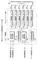
図2は、本発明による画像表示装置の実施形態となる機能構成のブロック図である。図2において、本発明の画像表示装置はパーソナルコンピュータ10とディスプレイ装置12で構成され、ディスプレイ装置12はパーソナルコンピュータ10に対しディスプレイコネクトケーブル14により接続されている。
FIG. 2 is a block diagram of a functional configuration according to the embodiment of the image display apparatus according to the present invention. In FIG. 2, the image display device of the present invention includes a personal computer 10 and a
パーソナルコンピュータ10とディスプレイ装置12の構成は、それぞれが別の装置としてケーブル接続されるデスクトップタイプはもちろんのこと、本体とディスプレイが一体化されたノートブックタイプであってもよい。
The configuration of the personal computer 10 and the
パーソナルコンピュータ10には、OS15、グラフィックコントローラ18、通信インタフェース20が設けられ、OS15によって1または複数の動画アプリケーションが実行される。この例では2つの動画アプリケーション16−1,16−2が実行されている状態を表している。
The personal computer 10 is provided with an
動画アプリケーション16−1,16−2による動画処理で得られた動画情報は、グラフィックコントローラ18によりフィールド単位又はフレーム単位の動画画面に変換され、通信インタフェース20を介してディスプレイ装置12にRGBの各アナログ信号として送られて表示される。
The moving image information obtained by the moving image processing by the moving image applications 16-1 and 16-2 is converted into a moving image screen in a field unit or a frame unit by the
ディスプレイ装置12は、通信インタフェース28、コントローラ30、信号処理回路32、液晶ユニット34及びテレビアンテナ48が接続されたテレビチューナ48を備える。
The
液晶ユニット34には、バックライト制御回路36、バックライト38及び液晶パネル40が設けられる。バックライト制御回路36は制御部とインバータ電源を内蔵してバックライト38を点灯駆動しており、本発明で使用する液晶ユニット34にあっては、コントローラ30からの制御信号により、バックライト制御回路36によるバックライト38を動画対応の同期モードと静止画対応の非同期モードが切替制御できるようにしている。またバックライト38の明るさは、バックライトの点滅制御におけるオン周期(オンデューティ)を変化させるPWM(パルス幅変調)により調光される。
The
信号処理回路32はパーソナルコンピュータ10又はテレビチューナ48からのRGB信号をA/D変換して液晶パネル40に表示させる。またテレビチューナ48はリモコン受信部を備え、図示しないハンディタイプのテレビコントローラ(リモートコントローラ)からの信号を受信してチャンネル切替えやボリューム調整等に加え、画面の明るさの制御をコントローラ30に対し行う。
The signal processing circuit 32 A / D converts RGB signals from the personal computer 10 or the
パーソナルコンピュータ10の通信インタフェース20とディスプレイ装置12の通信インタフェース28を接続するディスプレイコネクトケーブル14は、ディスプレイ制御信号42とRGB信号44を伝送する。
The display connect
ディスプレイ制御信号42の中にはバックライト制御信号が含まれている。ディスプレイ制御信号42として、この実施形態にあっては、RGB信号44のためのVGAコネクタ(Video Graphics Array)に含まれるDDCライン上のVESA(Video Electronics Standards Association)規格のDDC−2bi規格に従ったコマンドセットをバックライト制御信号として使用している。
The
ここでDDC−2bi規格のコマンドセットにあっては、ディスプレイ装置12に設けているバックライト38の動作を画像のフィールドまたはフレームの切替えに同期して点滅させる動画対応の同期モードと、バックライト38をフレーム切替えと非同期に且つフレーム周期より短い周期で点滅させる静止画対応の非同期モードとに切替制御することができる。
Here, in the command set of the DDC-2bi standard, a synchronization mode corresponding to a moving image for causing the operation of the
具体的には、バックライト38の同期モードによる動作はスキャンバックライトオンの16進オペコードDDhをもつコマンドセットにより指示され、また非同期モードはスキャンバックライトオフの16進オペコードDEhをもつコマンドセットにより指示される。
Specifically, the operation of the
このような外部信号によりバックライト38の動作を同期モードと非同期モードに切替可能なディスプレイ装置12を備えたパーソナルコンピュータ10につき、本発明にあっては、動画アプリケーション16−1,16−2に対する画像監視を行う常駐プログラムとして動作する画像監視部22を設けている。
According to the present invention, the personal computer 10 having the
画像監視部22は、動画処理検出部24と画面状態監視部26を備えている。動画処理検出部24は、OS16により実行中の処理の中から、ディスプレイ装置12に動画を表示させる動画アプリケーション16−1,16−2を検出する。画面状態監視部26は、動画処理検出部24で検出された動画アプリケーション16−1,16−2の表示画面状態に応じて、ディスプレイ装置12にバックライト38の同期モードまたは非同期モードを指示する。
The
即ち画面状態監視部26は、実行中の動画アプリケーションによるウィンドウが最前面にあり且つウィンドウサイズが最大化されたことを検出して、ディスプレイ装置12に対しバックライト38の同期モードを指示する。一方、ディスプレイ装置12にバックライト38の同期モードを指示する。
That is, the screen
またバックライト38の同期モードの状態で、実行中の動画アプリケーションのウィンドウサイズが最大サイズから変更されたことまたはウィンドウが最前面から後退したことを検出した場合には、ディスプレイ装置12にバックライト38の非同期モードへの切替えを指示することになる。
Further, when it is detected that the window size of the video application being executed has been changed from the maximum size or the window has retracted from the foreground while the
ここで、画面状態監視部26によるウィンドウサイズとウィンドウ画面位置の検出は、OS15のアプリケーションインタフェース(以下「API」という)を通じて取得することができる。
Here, the detection of the window size and the window screen position by the screen
APIを通じでOS15から取得された動画のウィンドウ枠の座標は、ディスプレイ表示サイズの座標と比較され、両座標が一致したときに動画のウィンドウサイズが最大化されたことを検出できる。またウィンドウの画面位置についても、OS15のAPIを通じて画面位置情報を取得し、最前面か否かを検出することができる。
The coordinates of the window frame of the moving image acquired from the
図1におけるパーソナルコンピュータ10は、例えば図3のようなコンピュータのハードウェア資源により実現される。図3のコンピュータにおいて、CPU100のバス101にはRAM102、ハードディスクコントローラ(ソフト)104、フロッピィディスクドライバ(ソフト)110、CD−ROMドライバ(ソフト)114、マウスコントローラ118、キーボードコントローラ122、グラフィックコントローラ18、通信用ボード130が接続される。
The personal computer 10 in FIG. 1 is realized by hardware resources of a computer as shown in FIG. 3, for example. In the computer of FIG. 3, a
ハードディスクコントローラ104はハードディスクドライブ106を接続し、本発明の画像監視処理を実行するプログラムをローディングしており、コンピュータの起動時にハードディスクドライブ106から必要なプログラムを呼び出して、RAM102上に展開し、CPU100により実行する。
The
フロッピィディスクドライバ110にはフロッピィディスクドライブ(ハード)112が接続され、フロッピィディスク(R)に対する読み書きができる。CD−ROMドライバ114に対しては、CDドライブ(ハード)116が接続され、CDに記憶されたデータやプログラムを読み込むことができる。
A floppy disk drive (hardware) 112 is connected to the
マウスコントローラ118はマウス120の入力操作をCPU100に伝える。キーボードコントローラ122はキーボード124の入力操作をCPU100に伝える。グラフィックコントローラ18はディスプレイ装置12に対して表示を行う。通信用ボード130は無線を含む通信回線132を使用し、ネットワーク内の装置や外部のインタネット上の装置との間で通信を行う。
The
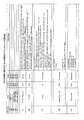
図4は、本発明のバックライト制御信号として使用されるVESA規格で規定される2Bi規格のコマンドセットの説明図である。このコマンドセットはオペコード、フィールド、リードライトフラグ、バリューを含み、本発明のバックライト制御信号としては、オペコードが「DCh」として示されたディスプレイモードのコマンドセットを使用する。 FIG. 4 is an explanatory diagram of a 2Bi standard command set defined by the VESA standard used as the backlight control signal of the present invention. This command set includes an operation code, a field, a read / write flag, and a value. As the backlight control signal of the present invention, a display mode command set in which the operation code is indicated as “DCh” is used.
このコマンドセットにあっては、バリューとしてその説明の欄に示すように0〜4の値を取り、バリュー1はDCh、バリュー2はDDh、バリュー3はDEh、バリュー4はDFhとなる。このうちオペコードがDDh及びDEhの内容が
2:スキャンバックライトオフ
3:スキャンバックライトオン
となって、前者がバックライトの同期モードのオフ即ち非同期モードを指示し、後者がバックライトの同期モードのオンを指示する。
In this command set, values take values from 0 to 4 as shown in the description column.
即ち、図2の画像監視部22に設けた画面状態監視部26が、OS15により実行中の例えば動画アプリケーション16−1についてウィンドウが最大化され且つウィンドウが最前面にあることを判別したとき、グラフィックコントローラ18にバックライトの同期モードを指示する。
That is, when the screen
これを受けて通信インタフェース20がディスプレイ制御信号42の中のバックライト制御信号として、図4の2Bi規格のコマンドセットに従ったオペコードDEhのスキャンバックライトオンの内容を持つコマンドセットを送信し、これを受けてディスプレイ装置12のコントローラ30が液晶ユニット34に設けているバックライト制御回路36のオン、オフ制御により、バックライト38を画像のフレーム周期に同期して点滅させ、動画対応としての液晶パネルの照明を行う。
In response to this, the
一方、パーソナルコンピュータ10の画像監視部22に設けた画面状態監視部26で、現在バックライト38の同期モードとしている動画アプリケーション16−1について、そのウィンドウが縮小されたり後ろ画面に移動したことなどを検出した場合には、このときディスプレイ装置12の液晶パネル40には静止画像が表示されるため、グラフィックコントローラ18に対し非同期モードへの切替えを指示する。
On the other hand, the screen
これを受けて通信インタフェース20は、ディスプレイ装置12に対し図4におけるオペコードDDhのスキャンバックライトオフを指示するコマンドセットをディスプレイ制御信号42として伝送する。この場合、ディスプレイ装置12のコントローラ30は、液晶ユニット34のインバータ36をフレーム周期とは非同期に且つフレーム周期より短い周期でバックライト38を点滅させ、静止画対応としての液晶パネルの照明を行う。
In response to this, the
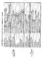
図5は、図2の画面状態監視部26において、OS15のAPIを通じてウィンドウに関する情報を取得するためのコマンドの一覧を示している。
FIG. 5 shows a list of commands for acquiring information about the window through the API of the
図5(A)はAPIに対するウィンドウ情報検索用コマンドの一覧であり、この中のコマンド「GetWindowRect」によって動画ウィンドウの座標を取得することができる。 FIG. 5A is a list of window information search commands for the API, and the coordinates of the moving image window can be acquired by a command “GetWindowRect” therein.
また図5(B)はウィンドウ検索用コマンド一覧であり、この中のコマンド「GetForegroundWindow」によって前景ウィンドウに対するハンドルを返すことによって、ウィンドウの位置を検出することができる。もちろん、実行中の動画画面に関する最大化検出及びウィンドウ最前面の検出は、OS15の参照により取得可能な適宜の情報を用いて行うことができる。
FIG. 5B shows a window search command list. By returning a handle for the foreground window by the command “GetForegroundWindow”, the position of the window can be detected. Of course, the maximization detection and the window foreground detection regarding the moving image screen being executed can be performed using appropriate information that can be acquired by referring to the
図6は、図2のパーソナルコンピュータ10に設けた画像監視部22による画像監視処理のフローチャートであり、このフローチャートが常駐プログラムとして動作する画像監視プログラムの処理内容を同時に表している。
FIG. 6 is a flowchart of image monitoring processing by the
図6において、パーソナルコンピュータ10のOS15が起動されると、常駐プログラムとしてインストールされている画像監視部22が実行され、まずステップS1でモニタレディをチェックする。
In FIG. 6, when the
このモニタレディはディスプレイ装置12からのデバイスステータスをチェックすることで判断できる。ステップS1でモニタレディが判別されるとステップS2に進み、一方、モニタレディが得られない場合にはステップS13に進み、例外処理を行って処理を終了する。
This monitor ready can be determined by checking the device status from the
モニタレディが得られてステップS2に進むと、バックライトの動作モードを含む初期値読み込みを行い、ステップS3でバックライトの非同期モードを初期設定する。そしてステップS4で、ディスプレイ装置12に対しバックライトの非同期モードを指示する。
When the monitor ready is obtained and the process proceeds to step S2, the initial value reading including the operation mode of the backlight is performed, and the asynchronous mode of the backlight is initialized in step S3. In step S4, the
次にステップS5で、起動中のアプリケーションリストをOS15からAPIを通じて取得する。続いてステップS6で、取得した起動中のアプリケーションの中にバックライト操作対象の動画アプリケーションがあるか否かチェックする。
In step S5, the active application list is acquired from the
動画アプリケーションがあればステップS7に進み、APIを通じてOS15より動画アプリケーションのウィンドウ枠の座標を取得する。そしてステップS8で、取得したウィンドウ枠の座標とディスプレイ表示座標とを比較し、一致する最大サイズか否かチェックする。
If there is a moving image application, the process proceeds to step S7, and the coordinates of the window frame of the moving image application are acquired from the
最大サイズであればステップS9に進み、APIを通じてOS15より同じ動画アプリケーションの画面の位置即ちウィンドウ前後位置に関する情報を取得する。そしてステップS10でウィンドウが最前面であるか否かチェックし、最前面であれば、ステップS11でディスプレイ装置12に対しバックライトの同期モードを設定して指示する。ステップS11でバックライトの同期モードを指示した後は、ステップS6に戻り、ステップS6からの処理を繰り返している。
If it is the maximum size, the process proceeds to step S9, and information regarding the screen position of the same moving image application, that is, the window front and rear position is acquired from the
この状態で、現在表示中の動画アプリケーションを停止したり、他の動画アプリケーションを起動してそのウィンドウを最前面としたり、更には動画アプリケーション以外のアプリケーションについて静止画をウィンドウ最前面としたような場合には、ステップS8またはステップS10でその状態が判別され、ステップS12に進み、ディスプレイ装置12に対しバックライトの非同期モードを設定して切替えを指示する。
In this state, when the currently displayed video application is stopped, another video application is started and the window is brought to the foreground, or a still image is brought to the front of the window for applications other than the video application In step S8 or step S10, the state is determined, and the process proceeds to step S12 to set the backlight asynchronous mode and instruct the switching to the
即ち、ステップS8で動画画面が縮小もしくは停止されて最大サイズでなくなった場合あるいはステップS10で動画ウィンドウが最前面でなくなった場合には、ステップS12でバックライトの非同期モードへの切り替えを指示することになる。 That is, when the moving image screen is reduced or stopped at step S8 and is no longer at the maximum size, or when the moving image window is not at the forefront at step S10, an instruction to switch the backlight to the asynchronous mode is issued at step S12. become.
このように本発明の画像監視処理にあっては、ディスプレイ装置12に動画画像を前面表示している場合には自動的にバックライトの同期モードとなって、動画再生時の残像感の軽減が図られ、一方、動画を停止したり動画画面を後ろ画面として静止画面を前画面としたような場合には自動的にバックライトが非同期モードに切り替わり、これによって静止画表示状態での画面のちらつきを軽減することができ、このようなバックライトの動画及び静止画に対応した最適な動作モードは、ユーザが特に意識することなく常に最適なバックライトの動作モードの制御状態が得られることになる。
As described above, in the image monitoring process of the present invention, when a moving image is displayed on the
図7は、本発明の表示制御装置が適用されるディスプレイ装置の組立分解図である。図7において、液晶ディスプレイ装置12は、液晶パネル40と、その直下に配置されるバックライト38で構成される。
FIG. 7 is an exploded view of a display device to which the display control device of the present invention is applied. In FIG. 7, the liquid
液晶パネル40は、この実施形態にあっては縦方向に6つの分割表示領域50−1〜50−6に分割されている。分割表示領域50−1〜50−6は液晶パネル40に対する画像のフレーム周期ごとに、分割表示領域50−1から分割表示領域50−6に向けて順番に画像の書替えが行われる。
In this embodiment, the
図8は、図7のバックライト38の組立分解図である。バックライト38はフレーム52、拡散板54及び本体56で構成される。本体56の液晶パネルの直下となる位置には、この実施形態にあっては12本の冷陰極管60−1〜60−12を縦方向に並べて配置している。
FIG. 8 is an exploded view of the
図9は、図2のディスプレイ装置12に設けているバックライト制御回路36のブロック図である。バックライト制御回路36は、制御部36−1と駆動部36−2で構成される。制御部36−1には順次信号発生回路62、同期制御回路64、非同期制御回路66及び切替制御回路68が設けられている。
FIG. 9 is a block diagram of the
順次信号発生回路62と同期制御回路64は切替制御回路68による動画モードの切替えで動作する。一方、非同期制御回路66は切替制御回路68による静止画対応の非同期モードで動作する。
The sequential
動画対応の同期制御を行う順次信号発生回路62に対しては、データイネーブル信号に基づいて生成された順次書替え信号E1と輝度制御信号E2が入力され、同期制御回路64に対しフレーム周期で順次書き替えられる液晶パネルの分割表示領域に対応してバックライトを点灯するための書替え開始信号を出力する。
A sequential rewrite signal E1 and a luminance control signal E2 generated based on the data enable signal are input to the sequential
切替制御回路68にはモード切替信号E4が与えられ、動画対応の同期モードと静止画対応の非同期モードを切り替える。このモード切替信号E4は図2のパーソナルコンピュータ10側からコントローラ30を経由して与えられる。なおテレビチューナ46によりテレビジョン放送を受信表示する際には、モード切替信号E4は強制的に同期モードへの切替信号となる。
A mode switching signal E4 is supplied to the switching
駆動部36−2には、図7に示した液晶パネル40の6つの分割表示領域50−1〜50−6に対応して、同じく6つのインバータ電源部70−1〜70−6が設けられ、バックライト38に対し駆動信号E31〜E36を出力する。
The drive unit 36-2 is similarly provided with six inverter power supply units 70-1 to 70-6 corresponding to the six divided display areas 50-1 to 50-6 of the
図10は、図9の駆動部36−2で駆動するバックライト38に内蔵した冷陰極管60−1〜60−12の配置説明図である。図10において、バックライト38には、図8の組立分解図に示したように12本の冷陰極管60−1〜60−12が縦方向に並べて配置されている。
FIG. 10 is a layout explanatory diagram of the cold cathode fluorescent lamps 60-1 to 60-12 built in the
冷陰極管60−1〜60−12は2本を一組としてインバータ電源部70−1〜70−6からの駆動信号E31〜E36が与えられ、2本単位に点滅制御される。このためバックライト38は、冷陰極管60−1〜60−12の右側に示すように、2本単位で6つの発光部76−1〜76−6を構成することになる。
The cold cathode fluorescent lamps 60-1 to 60-12 are supplied with drive signals E31 to E36 from the inverter power supply units 70-1 to 70-6 as a set, and are controlled to blink in units of two. For this reason, as shown in the right side of the cold cathode fluorescent lamps 60-1 to 60-12, the
図11は、図9のバックライト制御回路の詳細を示した回路ブロック図である。図11において、順次信号発生回路62、非同期制御回路66、切替制御回路68及びインバータ電源部70−1〜70−6は、図9の実施例と同じであるが、同期制御回路部64についてその詳細を示している。
FIG. 11 is a circuit block diagram showing details of the backlight control circuit of FIG. In FIG. 11, the sequential
同期制御回路64には図10のバックライト38における発光部76−1〜76−6に対応して、6つの三角波生成回路72−1〜72−6と、比較器74−1〜74−6が設けられている。三角波生成回路72−1〜72−6に対しては、順次信号発生回路62に入力する順次書替え信号E1に基づいて生成した図7の液晶パネル40における分割表示領域50−1〜50−6に対応した画像書替えの開始タイミングを決める書替え開始信号E01〜E06が入力される。
The
三角波生成回路72−1〜72−6はフレーム周期ごとに書替え開始信号E01〜E06の入力を順次受けて、三角波信号(鋸歯信号)E11〜E16を順次、比較器74−1〜74−6のプラス入力端子に出力する。比較器74−1〜74−6のマイナス入力端子に対しては、比較信号生成回路65から基準信号E5が共通に入力されている。 The triangular wave generation circuits 72-1 to 72-6 receive the rewrite start signals E01 to E06 sequentially every frame period, and sequentially receive the triangular wave signals (sawtooth signals) E11 to E16 of the comparators 74-1 to 74-6. Output to the positive input terminal. The reference signal E5 is commonly input from the comparison signal generation circuit 65 to the negative input terminals of the comparators 74-1 to 74-6.
比較信号生成回路65は平滑回路65−1を有し、順次信号発生回路62に対する輝度制御信号E2を平滑して電圧レベルに変換し、これを基準信号E5として出力する。輝度制御信号E2は、フレーム周期ごとに、あるオンデューティを持ったパルス信号であり、オンデューティを変化させることで基準信号E5の電圧レベルを変化させることができる。
The comparison signal generation circuit 65 has a smoothing circuit 65-1, and sequentially smoothes the luminance control signal E2 for the
比較器74−1〜74−6は、三角波生成回路72−1〜72−6から順次出力される三角波信号E11〜E16と基準信号E5を比較し、比較器出力信号E21〜E26をインバータ電源部70−1〜70−6に出力する。即ち比較器74−1〜74−6は、三角波信号E11〜E16が基準信号E5より低い場合は比較器出力信号E21〜E26はLレベルにあり、基準信号E5を超えると比較器出力信号E21〜E26がHレベルとなり、これによってインバータ電源部70−1〜70−6を順次オンして、バックライト38の対応する発光部76−1〜76−6の冷陰極管を2本単位で順次点灯する。
Comparators 74-1 to 74-6 compare the triangular wave signals E11 to E16 sequentially output from the triangular wave generating circuits 72-1 to 72-6 with the reference signal E5, and the comparator output signals E21 to E26 are connected to the inverter power supply unit. Output to 70-1 to 70-6. That is, in the comparators 74-1 to 74-6, when the triangular wave signals E11 to E16 are lower than the reference signal E5, the comparator output signals E21 to E26 are at the L level, and when exceeding the reference signal E5, the comparator output signals E21 to E21. E26 becomes H level, thereby turning on the inverter power supply units 70-1 to 70-6 sequentially, and sequentially turning on the cold cathode tubes of the corresponding light emitting units 76-1 to 76-6 of the
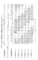
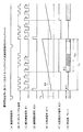
図12は、図11のバックライト制御回路36による動画対応となる同期モードのタイムチャートである。図12(A)は垂直同期信号であり、画像表示のフレーム周期を決めており、垂直同期信号の周波数は60Hzである。図12(B)は液晶パネル40に対する画像表示データの転送に使用されるデータイネーブル信号である。
FIG. 12 is a time chart of a synchronous mode corresponding to a moving image by the
データイネーブル信号は、垂直同期信号よりやや遅れてコントローラ30によって、順次生成され、液晶パネル40の水平走査線方向の描画の基準となる。例えば液晶パネル40の水平走査線数を768本とすると、1本単位にデータイネーブル信号の1クロックによる画像データの転送を行っており、したがって1フレームにおけるデータイネーブル信号のクロック数は768クロックとなる。
The data enable signal is sequentially generated by the
垂直同期信号が立ち上がってから、データイネーブル信号が送られるまでの時間をバックポーチ幅という。バックポーチ幅は、ディスプレイ装置12に表示画像データを送出する機器によって決定される。バックポーチ幅は解像度によって異なり、例えば、XGAの解像度をもつパーソナルコンピュータの場合、29Th(20.67μm)である。
The time from when the vertical synchronization signal rises to when the data enable signal is sent is called the back porch width. The back porch width is determined by a device that sends display image data to the
なお、図11(A)の<BP>はバックポーチ、<FB>はフロントポーチであり、図11(B)については一例として水平同期信号周期Hsを単位として具体的な数値を示している。 Note that <BP> in FIG. 11A is a back porch and <FB> is a front porch. FIG. 11B shows specific numerical values in units of a horizontal synchronizing signal cycle Hs as an example.
図12(C)は順次書替え信号E1であり、データイネーブル信号を6分の1に分周することにより生成して、図2のコントローラ30からバックライト制御回路36に供給している。この順次切替信号E1は垂直同期信号で決まる1フレーム周期内で図7の液晶パネル40の6つの分割表示領域50−1〜50−6に対応して、1〜6の数字で示す6つのパルス信号を出力している。
FIG. 12C shows a sequential rewrite signal E1, which is generated by dividing the data enable signal by 1/6 and is supplied from the
図12(D)〜(I)は、インバータ電源部70−1〜70−6からの駆動信号E31〜E36により駆動される図10のバックライト38における発光部76−1〜76−6のバックライトのオフ、オンの点滅状態である。例えば図12(D)の発光部76−1を見ると、順次書替え信号E1の最初のパルスの立ち上がりに同期して発光部76−1はオフとなり、順次書替え信号E1の4パルス目の立ち上がり近傍でオンし、次のフレーム周期における最初のパルスの立ち上がりでオフとなり、これを繰り返している。
12D to 12I show the backlights of the light emitting units 76-1 to 76-6 in the
ここでフレーム周期はT1であり、フレーム周期T1の前半がオフとなり、後半のオン時間Tonの間、点灯している。このため、発光部76−1のフレーム周期における点灯時間を決めるオンデューティは(Ton/T1)となる。 Here, the frame period is T1, the first half of the frame period T1 is turned off, and it is lit during the latter on-time Ton. For this reason, the on-duty which determines the lighting time in the frame period of the light emission part 76-1 becomes (Ton / T1).
フレーム周期におけるオン時間Tonは、後の説明で明らかにするように、図11の比較信号生成回路65に対する輝度制御信号E2に応じて変化する。本発明の実施形態にあっては、輝度制御信号E2によってバックライト点灯のためのオンデューティを0.1〜0.9の範囲で調整することができる。 The on-time Ton in the frame period changes according to the luminance control signal E2 for the comparison signal generation circuit 65 in FIG. 11, as will be apparent from the following description. In the embodiment of the present invention, the on-duty for lighting the backlight can be adjusted in the range of 0.1 to 0.9 by the luminance control signal E2.
図12(E)〜(I)の残りの発光部76−2〜76−6については、順次書替え信号E1の2パルス目、3パルス目、4パルス目、5パルス目、6パルス目の立ち上がりに同期して、3パルス目でオンとなり、次のフレーム周期における順次切替信号E1の同じ2パルス目、3パルス目、4パルス目、5パルス目、6パルス目の立ち上がりでオフとなっている。 For the remaining light emitting units 76-2 to 76-6 in FIGS. 12E to 12I, the second pulse, the third pulse, the fourth pulse, the fifth pulse, and the sixth pulse of the rewrite signal E1 are sequentially raised. Is turned on at the third pulse and turned off at the rising edge of the same second pulse, third pulse, fourth pulse, fifth pulse, and sixth pulse of the sequential switching signal E1 in the next frame period. .
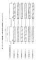
図13は、データイネーブル信号に同期した順次書替え信号E1から生成される書替え開始信号E01〜E06のタイムチャートである。図13において、(A)の垂直同期信号、(B)のデータイネーブル信号、更に(D)の順次書替え信号E1は、図12のタイムチャートと同じである。また図13(C)には輝度制御信号E2を示しており、このオンデューティにより動画対応の同期モードにおける液晶パネルの明るさを制御することができる。 FIG. 13 is a time chart of the rewrite start signals E01 to E06 generated from the sequential rewrite signal E1 synchronized with the data enable signal. In FIG. 13, the vertical synchronization signal (A), the data enable signal (B), and the sequential rewrite signal E1 (D) are the same as those in the time chart of FIG. FIG. 13C shows the luminance control signal E2, and the brightness of the liquid crystal panel in the synchronous mode corresponding to the moving image can be controlled by this on-duty.
図13(D)の順次書替え信号E1を入力した図11の順次信号発生回路62は、図13(E)〜(J)に示すように、それぞれの立ち上がりに同期して書替え開始信号E01〜E06を順次出力する。この書替え開始信号E01〜E06は図11の同期制御回路64に設けた三角波生成回路72−1〜72−6に入力され、一定の傾きを持つ三角波信号E11〜E16を順次出力する。
The sequential
図14は、図13の書替え開始信号に基づいて生成するバックライト点滅制御信号のタイムチャートであり、図13(E)の書替え開始信号E01に基づくインバータ電源部70−1による発光部76−1の点滅制御を例に取っている。 FIG. 14 is a time chart of the backlight blinking control signal generated based on the rewrite start signal in FIG. 13, and the light emitting unit 76-1 by the inverter power supply unit 70-1 based on the rewrite start signal E01 in FIG. The flashing control is taken as an example.
図14(A)の垂直同期信号、(C)の順次書替え信号E1及び(D)の書替え開始信号E01は、図13と同じである。図14(E)は図11の三角波生成回路72−1から出力される三角波信号E11であり、書替え開始信号E01の立ち上がりのタイミングで三角波信号E11のリセットスタートが行われ、一定勾配で出力レベルが増加する。三角波信号E11は図11の比較器74−1のプラス入力端子に入力され、一方、比較器74−1には、そのときの輝度制御信号E2の平滑で得られたレベルをもつ基準信号E5が入力している。 The vertical synchronization signal in FIG. 14A, the sequential rewrite signal E1 in (C), and the rewrite start signal E01 in (D) are the same as in FIG. FIG. 14E shows a triangular wave signal E11 output from the triangular wave generation circuit 72-1 of FIG. 11. The triangular wave signal E11 is reset at the rising timing of the rewrite start signal E01, and the output level is constant. To increase. The triangular wave signal E11 is input to the plus input terminal of the comparator 74-1 shown in FIG. 11. On the other hand, the reference signal E5 having a level obtained by smoothing the luminance control signal E2 at that time is supplied to the comparator 74-1. You are typing.
このため、三角波信号E11が基準信号E5に達した時刻t1のタイミングで、図14(F)のように比較器出力信号E21がHレベルとなり、インバータ電源部70−1を動作し、駆動信号E31をバックライト38に出力し、図10における発光部76−1に含まれる2本の冷陰極管60−1,60−2を点灯駆動する。
Therefore, at the time t1 when the triangular wave signal E11 reaches the reference signal E5, the comparator output signal E21 becomes H level as shown in FIG. 14F, the inverter power supply unit 70-1 is operated, and the drive signal E31. Is output to the
三角波信号E11は、次のフレーム周期で書替え開始信号E01が立ち上がるとリセットスタートされ、これにより比較器出力信号E21はLレベルとなって発光部76−1が消灯する。 The triangular wave signal E11 is reset when the rewrite start signal E01 rises in the next frame period, whereby the comparator output signal E21 becomes L level and the light emitting section 76-1 is turned off.
動画対応時の液晶パネル画面の明るさは、図13(C)の輝度制御信号E2のオンデューティを増加させると、図14(E)における基準信号E5のレベルが減少し、発光部のオン時間Tonが長くなり、これによって画面の明るさが上昇する。一方、図13(C)の輝度制御信号E2のオンデューティを小さくすれば、図14(E)の基準信号E5が増加し、発光部におけるオン時間Ton減少することで画面の明るさを下げることができる。 When the on-duty of the luminance control signal E2 in FIG. 13C is increased, the level of the reference signal E5 in FIG. Ton becomes longer, which increases the brightness of the screen. On the other hand, if the on-duty of the luminance control signal E2 in FIG. 13 (C) is reduced, the reference signal E5 in FIG. 14 (E) increases, and the on-time Ton in the light emitting unit decreases, thereby reducing the screen brightness. Can do.
この図12〜図14のタイムチャートから明らかなように、動画対応となる同期モードでのバックライトの点滅制御にあっては、データイネーブル信号の分周により得られた順次書替え信号E1に基づく書替え開始信号E01〜E06に同期してフレーム周期の前半でバックライトが消灯し、後半でバックライトが点灯する点滅制御が行われることで、液晶パネルにおける分割表示領域50−1〜50−6の画像書替えに適切に同期し、且つ書替えによる画像変化が収まるフレーム周期の後半のタイミングでバックライトが点灯することで、動画表示の際の残像を低減して動画品質を向上することができる。 As is apparent from the time charts of FIGS. 12 to 14, in the flashing control of the backlight in the synchronous mode corresponding to the moving image, rewriting based on the sequential rewriting signal E1 obtained by dividing the data enable signal. By performing blinking control in which the backlight is turned off in the first half of the frame period and the backlight is turned on in the second half in synchronization with the start signals E01 to E06, the images of the divided display areas 50-1 to 50-6 in the liquid crystal panel Since the backlight is turned on at the second half of the frame period in which the image change caused by rewriting is settled appropriately in synchronization with rewriting, it is possible to reduce the afterimage when displaying the moving image and improve the moving image quality.
また、同期モードにおけるバックライトの点灯制御を、垂直同期信号によらず、液晶パネルに対するデータ転送のデータイネーブル信号を分周して得た順次書替え信号により同期を取って点滅制御しているため、液晶パネルの分割表示領域の書替えに適切に同期した残像防止のためのバックライト点滅制御ができる。また、データイネーブル信号に基づいた同期によるバックライトの点滅制御であることから、垂直同期信号に対し同期を取る場合に比べ、データイネーブル信号の単純な分周により同期が得られることで、回路構成を簡単にすることができる。 In addition, the lighting control of the backlight in the synchronous mode is controlled by blinking in synchronization with the sequential rewrite signal obtained by dividing the data enable signal of the data transfer to the liquid crystal panel, regardless of the vertical synchronization signal. It is possible to perform backlight blinking control for preventing afterimages appropriately synchronized with rewriting of the divided display area of the liquid crystal panel. In addition, since the backlight blinking is controlled by synchronization based on the data enable signal, the circuit configuration can be achieved by synchronization by simply dividing the data enable signal as compared with the case of synchronizing with the vertical synchronization signal. Can be easy.
図15は、図11のバックライト制御回路36に設けた非同期制御回路66による静止画対応の非同期モードのバックライト点滅動作のタイムチャートである。図15(A)は非同期点滅制御信号E6であり、フレーム周期を与える垂直同期信号やデータイネーブル信号との同期は取られておらず、ディスプレイ装置12で使用しているクロックに基づき、予め定めた一定周波数T2を持つ信号を使用している。
FIG. 15 is a time chart of the backlight blinking operation in the asynchronous mode corresponding to the still image by the
非同期点滅制御信号E6は信号周期T2の前半のオン時間Tonに同期して、図15(B)〜(G)のように発光部76−1〜76−6を一斉に点灯し、残りのオフ時間で一斉に消灯させる点滅制御を繰り返している。 Asynchronous flashing control signal E6 synchronizes with on-time Ton in the first half of signal cycle T2, and simultaneously turns on light emitting portions 76-1 to 76-6 as shown in FIGS. Flashing control that turns off all at once is repeated.
本発明の非同期点滅制御信号E6の周波数としては、フレーム周波数fの2倍周波数3fと4倍周波数4fとの加算平均周波数f2を使用している。ここでフレーム周波数fはf=60Hzであることから、非同期点滅制御信号E6の周波数f2は
f2=(2f+3f)/2=210Hz
となる。
As the frequency of the asynchronous blinking control signal E6 of the present invention, the addition average frequency f2 of the double frequency 3f and the quadruple frequency 4f of the frame frequency f is used. Here, since the frame frequency f is f = 60 Hz, the frequency f2 of the asynchronous blink control signal E6 is f2 = (2f + 3f) / 2 = 210 Hz.
It becomes.
静止画表示の際の非同期モードにおけるバックライト38の駆動周波数210Hzによれば、静止画表示状態で液晶パネルの表示画面にフレーム周波数の定倍周波数に起因して発生する縞模様を抑えることができる。
According to the driving frequency 210 Hz of the
なお、非同期点滅制御信号E6の周波数f2としては、一般的には、nを整数1,2,3,4,5・・・・とした場合、フレーム周波数fのn倍の周波数nfと(n+1)倍の周波数(n+1)fとの加算平均周波数であればよく、n=2であればf2=150Hz、n=4であればf2=270Hz、n=6であればf2=330Hzというように整数nに応じた適宜の周波数を選択できる。
As the frequency f2 of the asynchronous blink control signal E6, generally, when n is an
図15の非同期モードにおける液晶パネル表示画面の明るさ調整については、図11の非同期制御回路66に対する輝度制御信号E3によりオン時間Ton、即ち非同期点滅制御信号E6のオンデューティを変化させることで、静止画表示状態の明るさを調整できる。本発明の実施形態にあっては、非同期点滅制御信号E6のオンデューティを例えば0.25〜0.98の範囲で変化させて、画面の明るさを調整する。
For the brightness adjustment of the liquid crystal panel display screen in the asynchronous mode of FIG. 15, the on-time Ton, that is, the on-duty of the asynchronous blinking control signal E6 is changed by the luminance control signal E3 for the
なお、図7〜図15に示した本発明のディスプレイ装置における動画対応の同期モードにおけるバックライト点滅制御と静止画対応の非同期モードにおけるバックライト点灯制御は、図2に示したパーソナルコンピュータ10に使用されるディスプレイ装置12に限定されず、液晶パネルを表示デバイスとした適宜のディスプレイ装置にそのまま適用することができる。
The backlight blinking control in the synchronous mode corresponding to the moving image and the backlight lighting control in the asynchronous mode corresponding to the still image in the display device of the present invention shown in FIGS. 7 to 15 are used for the personal computer 10 shown in FIG. The present invention is not limited to the
なお本発明は、その目的と利点を損なうことのない適宜の変形を含み、更に上記の実施形態に示した数値による限定は受けない。
The present invention includes appropriate modifications that do not impair the objects and advantages thereof, and is not limited by the numerical values shown in the above embodiments.
ここで本発明の特徴を列挙すると次の付記のようになる。
(付記1)
分割された複数の表示領域を順次書き替える表示装置を照射し、分割された複数の発光領域を持つ発光装置を制御する発光制御装置において、
前記表示領域の書き替え開始に応じて、前記発光領域を順次点灯する制御を開始する発光制御部を備えることを特徴とする発光制御装置。(1)
Here, the features of the present invention are enumerated as follows.
(Appendix 1)
In a light emission control device that irradiates a display device that sequentially rewrites a plurality of divided display regions and controls a light emitting device having a plurality of divided light emission regions,
A light emission control device comprising: a light emission control unit that starts control to sequentially turn on the light emission areas in response to the start of rewriting of the display area. (1)
(付記2)
付記1記載の発光制御装置において、前記表示装置が表示する画像が動画であることを特徴とする発光制御装置。(2)
(Appendix 2)
The light emission control device according to
(付記3)
付記2記載の発光制御装置において、前記表示装置が表示する画像が動画でない場合は、所定の周波数に応じて前記複数の発光領域を同時に点灯制御することを特徴とする発光制御装置。(3)
(Appendix 3)
The light emission control device according to
(付記4)
付記1記載の発光制御装置において、各発光領域が対応する複数の表示領域の画像変化が収まった後に、前記発光領域を点灯制御することを特徴とする発光制御装置。(4)
(Appendix 4)
The light emission control device according to
(付記5)
付記1記載の発光制御装置において、表示装置の明るさを、各発光領域の点灯時間で調整することを特徴とする発光制御装置。(5)
(Appendix 5)
The light emission control device according to
(付記6)
付記1記載の発光制御装置において、前記表示領域の書き替え信号から、各発光領域の点灯制御の基準となる順次書替え信号を生成することを特徴とする発光制御装置。(6)
(Appendix 6)
The light emission control device according to
(付記7)
付記6記載の発光制御装置において、前記順次書替え信号の所定の変化時には、対応する前記発光領域を消灯し、設定した一定時間後に点灯する制御を行うことを特徴とする発光制御装置。(7)
(Appendix 7)
The light emission control device according to claim 6, wherein when the sequential rewrite signal is changed, the corresponding light emission region is turned off and the light emission control device is turned on after a predetermined time. (7)
(付記8)
分割された複数の表示領域を順次書き替える表示部と、分割された'数の発光領域を持ち、前記表示部を照射する発光部をもつ表示装置において、
前記表示領域の書き替え開始に応じて、前記発光領域を順次点灯する制御を開始する発光制御部を備えることを特徴とする表示装置。(8)
(Appendix 8)
In a display device having a display section that sequentially rewrites a plurality of divided display areas, and a light emitting section that irradiates the display section, having a divided number of light emitting areas.
A display device comprising: a light emission control unit that starts control to sequentially turn on the light emitting areas in response to the start of rewriting of the display area. (8)
(付記9)
付記8記載の表示装置において、表示する画像が動画であることを特徴とする表示装置。
(Appendix 9)
The display device according to appendix 8, wherein the image to be displayed is a moving image.
(付記10)
付記9記載の表示装置において、表示する画像が動画でない場合は、所定の周波数に応じて前記の発光領域を同時に点灯制御することを特徴とする表示装置。
(Appendix 10)
The display device according to
(付記11)
付記8記載の表示装置において、各発光領域が対応する複数の表示領域の画像変化が収まった後に、前記発光領域を点灯制御することを特徴とする表示装置。
(Appendix 11)
9. The display device according to appendix 8, wherein lighting control of the light emitting area is performed after image changes of a plurality of display areas corresponding to the respective light emitting areas are settled.
(付記12)
付記8記載の表示装置において、表示装置の明るさを、各発光領域の点灯時間で調整することを特徴とする表示装置。
(Appendix 12)
The display device according to appendix 8, wherein the brightness of the display device is adjusted by a lighting time of each light emitting area.
(付記13)
付記8記載の表示装置において、前記表示領域の順次書替え信号から、各発光領域の点灯制御信号を生成することを特徴とする表示装置。
(Appendix 13)
9. The display device according to appendix 8, wherein a lighting control signal for each light emitting region is generated from a sequential rewrite signal for the display region.
(付記14)
付記11記載の表示装置において、前記順次書替え信号の所定の変化時には、対応する前記発光領域を消灯し、設定した一定時間後に点灯する制御を行うことを特徴とする表示装置。
(Appendix 14)
The display device according to appendix 11, wherein when the sequential rewrite signal is changed in a predetermined manner, the corresponding light emitting area is extinguished and controlled to turn on after a predetermined time.
(付記15)
複数の処理を実行し、かつ表示装置を制御して画像を表示する情報装置において、
実行中の処理の中から、前記表示装置に動画を表示する動画処理を検出する動画処理出部と、
前記動画処理検出部が動画表示を検出した場合には、前記表示装置にちらつきの少ない表示制御を指示する表示制御部と、
を備えることを特徴とする情報装置。(9)
(Appendix 15)
In an information device that executes a plurality of processes and controls the display device to display an image,
A moving image processing output unit for detecting moving image processing for displaying a moving image on the display device from among the processes being executed;
When the moving image processing detection unit detects moving image display, a display control unit that instructs the display device to perform display control with less flickering;
An information device comprising: (9)
(付記16)
付記15記載の情報装置において、前記動画処理の表示状態を監視する画面状態監視部をさらに備え、前記動画処理の表示が一定以上の大きさのときに、前記表示装置にちらつきの少ない表示制御を指示することを特徴とする情報装置。
(Appendix 16)
The information device according to
(付記17)
付記15記載の情報装置において、
前記動画処理の表示と前記表示装置の表示領域の大きさが同じときに、前記表示装置にちらつきの少ない表示制御を指示することを特徴とする情報装置。
(Appendix 17)
In the information device according to
An information device characterized by instructing the display device to perform display control with little flicker when the display of the moving image processing and the display area of the display device are the same.
(付記18)
付記15記載の情報装置において、
前記表示制御は、VESA規格によって規定されるDDC−2bl規格に準じて指示することを特徴とする情報装置。
(Appendix 18)
In the information device according to
The display device is instructed in accordance with the DDC-2bl standard defined by the VESA standard.
(付記19)
複数の処理を実行し、かつ表示装置を制御して画像を表示する情報制御装置において、
実行中の処理の中から、前記表示装置に動画を表示する動画処理を検出する動画処理出部と、
前記動画処理検出部が動画表示を検出した場合には、前記表示装置にちらつきの少ない表示制御を指示する表示制御部と、
を備えることを特徴とする情報制御装置。
(Appendix 19)
In an information control device that executes a plurality of processes and displays an image by controlling a display device,
A moving image processing output unit for detecting moving image processing for displaying a moving image on the display device from among the processes being executed;
When the moving image processing detection unit detects moving image display, a display control unit that instructs the display device to perform display control with less flickering;
An information control apparatus comprising:
(付記20)
付記19記載の情報制御装置において、前記動画処理の表示状態を監視する画面状態監視部をさらに備え、前記動画処理の表示が一定以上の大きさのときに、前記表示装置にちらつきの少ない表示制御を指示することを特徴とする情報制御装置。
(Appendix 20)
The information control device according to appendix 19, further comprising a screen state monitoring unit that monitors a display state of the moving image processing, wherein the display device has less flicker when the display of the moving image processing is larger than a certain size. An information control apparatus characterized by instructing.
(付記21)
付記19記載の情報制御装置において、
前記動画処理の表示と前記表示装置の表示領域の大きさが同じときに、前記表示装置にちらつきの少ない表示制御を指示することを特徴とする情報装置。
(Appendix 21)
In the information control apparatus according to attachment 19,
An information device characterized by instructing the display device to perform display control with little flicker when the display of the moving image processing and the display area of the display device are the same.
(付記22)
付記19記載の情報制御装置において、
前記表示制御は、VESA規格によって規定されるDDC−2bl規格に準じて指示することを特徴とする情報装置。
(Appendix 22)
In the information control apparatus according to attachment 19,
The display device is instructed in accordance with the DDC-2bl standard defined by the VESA standard.
(付記23)
コンピュータに、
実行中の処理の中から、表示装置に動画を表示する動画処理を検出する動画処理出部と、
前記動画処理検出部が動画表示を検出した場合には、前記表示装置にちらつきの少ない表示制御を指示する表示制御部と、
を実行させるための表示制御プログラム。(10)
(Appendix 23)
On the computer,
A moving image processing output unit for detecting moving image processing for displaying a moving image on a display device from among the processing being executed;
When the moving image processing detection unit detects moving image display, a display control unit that instructs the display device to perform display control with less flickering;
Display control program to execute. (10)
(付記24)
付記23記載のプログラムにおいて、前記動画処理の表示状態を監視する画面状態監視部をさらに備え、前記動画処理の表示が一定以上の大きさのときに、前記表示装置にちらつきの少ない表示制御を指示することを特徴とするプログラム。
(Appendix 24)
The program according to attachment 23, further comprising a screen state monitoring unit that monitors a display state of the moving image processing, and instructing the display device to perform display control with less flicker when the display of the moving image processing is a certain size or more. The program characterized by doing.
(付記25)
付記23記載のプログラムにおいて、
前記動画処理の表示と前記表示装置の表示領域の大きさが同じときに、前記表示装置にちらつきの少ない表示制御を指示することを特徴とするプログラム。
(Appendix 25)
In the program described in Appendix 23,
A program for instructing the display device to perform display control with little flicker when the display of the moving image processing and the display area of the display device are the same.
(付記26)
付記23記載のプログラムにおいて、
前記表示制御は、VESA規格によって規定されるDDC−2bl規格に準じて指示することを特徴とするプログラム。
(Appendix 26)
In the program described in Appendix 23,
The display control is instructed according to the DDC-2bl standard defined by the VESA standard.
10:パーソナルコンピュータ
12:ディスプレイ装置
14:ディスプレイコネクトケーブル
15:OS
16,16−1,16−2:動画アプリケーション
18:グラフィックコントローラ
20,28:通信インターフェース
22:画像監視部
24:動画処理検出部
26:画面状態監視部
30:コントローラ
32:A/Dコンバータ
34:液晶ユニット
36:バックライト制御回路
36−1:制御部
36−2:駆動部
38:バックライト
40:液晶パネル
42:ディスプレイ制御信号
44:RGB信号
46:テレビチューナ
48:テレビアンテナ
50−1〜50−6:分割表示領域
52:フレーム
54:拡散板
56:本体
60−1〜60−12:冷陰極管
62:順次信号発生回路
64:同期制御回路
65:比較信号生成回路
65−1:平滑回路
66:非同期制御回路
68:切替制御回路
70−1〜70−6:インバータ電源部
72−1〜72−6:三角波生成回路
74−1〜74−6:比較器
76−1〜76−6:発光部
10: Personal computer 12: Display device 14: Display connect cable 15: OS
16, 16-1, 16-2: moving image application 18:
Claims (10)
前記表示領域の書き替え開始に応じて、前記発光領域を順次点灯する制御を開始する発光制御部を備えることを特徴とする発光制御装置。
In a light emission control device that irradiates a display device that sequentially rewrites a plurality of divided display regions and controls a light emitting device having a plurality of divided light emission regions,
A light emission control device comprising: a light emission control unit that starts control to sequentially turn on the light emission areas in response to the start of rewriting of the display area.
The light emission control device according to claim 1, wherein the image displayed by the display device is a moving image.
The light emission control device according to attachment 2, wherein when the image displayed by the display device is not a moving image, the plurality of light emission regions are controlled to be lighted simultaneously according to a predetermined frequency.
The light emission control device according to claim 1, wherein the light emission region is controlled to be turned on after the image change of the plurality of display regions corresponding to each light emission region is settled.
The light emission control device according to claim 1, wherein the brightness of the display device is adjusted by a lighting time of each light emitting region.
The light emission control device according to appendix 1, wherein a sequential rewrite signal serving as a reference for lighting control of each light emitting region is generated from the rewrite signal of the display region.
The light emission control device according to claim 6, wherein when the sequential rewrite signal is changed, the corresponding light emission region is turned off and the light emission control device is turned on after a predetermined time.
前記表示領域の書き替え開始に応じて、前記発光領域を順次点灯する制御を開始する発光制御部を備えることを特徴とする表示装置。
In a display device having a display section that sequentially rewrites a plurality of divided display areas, and a light emitting section that irradiates the display section, having a divided number of light emitting areas.
A display device comprising: a light emission control unit that starts control to sequentially turn on the light emitting areas in response to the start of rewriting of the display area.
実行中の処理の中から、前記表示装置に動画を表示する動画処理を検出する動画処理出部と、
前記動画処理検出部が動画表示を検出した場合には、前記表示装置にちらつきの少ない表示制御を指示する表示制御部と、
を備えることを特徴とする情報装置。
In an information device that executes a plurality of processes and controls the display device to display an image,
A moving image processing output unit for detecting moving image processing for displaying a moving image on the display device from among the processes being executed;
When the moving image processing detection unit detects moving image display, a display control unit that instructs the display device to perform display control with less flickering;
An information device comprising:
実行中の処理の中から、表示装置に動画を表示する動画処理を検出する動画処理出部と、
前記動画処理検出部が動画表示を検出した場合には、前記表示装置にちらつきの少ない表示制御を指示する表示制御部と、
を実行させるための表示制御プログラム。 On the computer,
A moving image processing output unit for detecting moving image processing for displaying a moving image on a display device from among the processing being executed;
When the moving image processing detection unit detects moving image display, a display control unit that instructs the display device to perform display control with less flickering;
Display control program to execute.
Priority Applications (7)
| Application Number | Priority Date | Filing Date | Title |
|---|---|---|---|
| JP2004000206A JP2005195734A (en) | 2004-01-05 | 2004-01-05 | Light-emitting control apparatus, display apparatus, display control apparatus and display control program |
| EP04020425A EP1551002A3 (en) | 2004-01-05 | 2004-08-27 | Control of synchronization of backlight for liquid crystal display apparatus |
| US10/930,527 US20050146532A1 (en) | 2004-01-05 | 2004-08-31 | Illumination control apparatus, display apparatus, display control apparatus and display control program |
| TW093126352A TWI282543B (en) | 2004-01-05 | 2004-09-01 | Illumination control apparatus, display apparatus, display control apparatus and computer-readable medium storing a display control program |
| KR1020040073687A KR20050072046A (en) | 2004-01-05 | 2004-09-15 | Apparatus for controlling light emitting, display device, apparatus for controlling display and program for controlling display |
| CNA2004100824703A CN1638587A (en) | 2004-01-05 | 2004-09-22 | Illumination control apparatus, display apparatus, display control apparatus and display control program |
| KR1020070123573A KR20080007200A (en) | 2004-01-05 | 2007-11-30 | Apparatus for controlling light emitting, display device, apparatus for controlling display and program for controlling display |
Applications Claiming Priority (1)
| Application Number | Priority Date | Filing Date | Title |
|---|---|---|---|
| JP2004000206A JP2005195734A (en) | 2004-01-05 | 2004-01-05 | Light-emitting control apparatus, display apparatus, display control apparatus and display control program |
Publications (2)
| Publication Number | Publication Date |
|---|---|
| JP2005195734A true JP2005195734A (en) | 2005-07-21 |
| JP2005195734A5 JP2005195734A5 (en) | 2006-07-20 |
Family
ID=34567568
Family Applications (1)
| Application Number | Title | Priority Date | Filing Date |
|---|---|---|---|
| JP2004000206A Withdrawn JP2005195734A (en) | 2004-01-05 | 2004-01-05 | Light-emitting control apparatus, display apparatus, display control apparatus and display control program |
Country Status (6)
| Country | Link |
|---|---|
| US (1) | US20050146532A1 (en) |
| EP (1) | EP1551002A3 (en) |
| JP (1) | JP2005195734A (en) |
| KR (2) | KR20050072046A (en) |
| CN (1) | CN1638587A (en) |
| TW (1) | TWI282543B (en) |
Cited By (11)
| Publication number | Priority date | Publication date | Assignee | Title |
|---|---|---|---|---|
| JP2007108484A (en) * | 2005-10-14 | 2007-04-26 | Matsushita Electric Ind Co Ltd | Liquid crystal display device |
| JP2007256355A (en) * | 2006-03-20 | 2007-10-04 | Sharp Corp | Display method and device |
| JP2008109219A (en) * | 2006-10-23 | 2008-05-08 | Funai Electric Co Ltd | Television and edid rewriting circuit |
| JP2009008946A (en) * | 2007-06-28 | 2009-01-15 | Kyocera Corp | Display device and display program |
| JP2009222979A (en) * | 2008-03-17 | 2009-10-01 | Seiko Epson Corp | Electro-optical device |
| JP2010061394A (en) * | 2008-09-03 | 2010-03-18 | Lenovo Singapore Pte Ltd | Information processor, software management method therefor, and computer executable program |
| JP2011227394A (en) * | 2010-04-22 | 2011-11-10 | Sharp Corp | Display device |
| WO2011149094A1 (en) * | 2010-05-28 | 2011-12-01 | シャープ株式会社 | Display device and display method |
| WO2013125073A1 (en) * | 2012-02-20 | 2013-08-29 | シャープ株式会社 | Backlight light source, backlight device, liquid crystal display device, and method for controlling lighting of backlight light source |
| US9019320B2 (en) | 2010-04-28 | 2015-04-28 | Semiconductor Energy Laboratory Co., Ltd. | Liquid crystal display device and electronic appliance |
| US9569992B2 (en) | 2012-11-15 | 2017-02-14 | Semiconductor Energy Laboratory Co., Ltd. | Method for driving information processing device, program, and information processing device |
Families Citing this family (31)
| Publication number | Priority date | Publication date | Assignee | Title |
|---|---|---|---|---|
| US9229222B2 (en) | 2005-02-23 | 2016-01-05 | Pixtronix, Inc. | Alignment methods in fluid-filled MEMS displays |
| US9261694B2 (en) | 2005-02-23 | 2016-02-16 | Pixtronix, Inc. | Display apparatus and methods for manufacture thereof |
| US7999994B2 (en) | 2005-02-23 | 2011-08-16 | Pixtronix, Inc. | Display apparatus and methods for manufacture thereof |
| US9158106B2 (en) | 2005-02-23 | 2015-10-13 | Pixtronix, Inc. | Display methods and apparatus |
| US8310442B2 (en) | 2005-02-23 | 2012-11-13 | Pixtronix, Inc. | Circuits for controlling display apparatus |
| US9082353B2 (en) | 2010-01-05 | 2015-07-14 | Pixtronix, Inc. | Circuits for controlling display apparatus |
| US8482496B2 (en) | 2006-01-06 | 2013-07-09 | Pixtronix, Inc. | Circuits for controlling MEMS display apparatus on a transparent substrate |
| US8519945B2 (en) | 2006-01-06 | 2013-08-27 | Pixtronix, Inc. | Circuits for controlling display apparatus |
| US8159428B2 (en) | 2005-02-23 | 2012-04-17 | Pixtronix, Inc. | Display methods and apparatus |
| US20070205969A1 (en) | 2005-02-23 | 2007-09-06 | Pixtronix, Incorporated | Direct-view MEMS display devices and methods for generating images thereon |
| US8526096B2 (en) | 2006-02-23 | 2013-09-03 | Pixtronix, Inc. | Mechanical light modulators with stressed beams |
| CN100511397C (en) * | 2006-02-28 | 2009-07-08 | 启萌科技有限公司 | Liquid-crystal display device and controlling method thereof |
| KR101252879B1 (en) * | 2006-06-29 | 2013-04-09 | 엘지디스플레이 주식회사 | Liquid crystal display device and method driving for the same |
| US9176318B2 (en) | 2007-05-18 | 2015-11-03 | Pixtronix, Inc. | Methods for manufacturing fluid-filled MEMS displays |
| US8531380B2 (en) * | 2008-07-22 | 2013-09-10 | Sharp Laboratories Of America, Inc. | Methods and systems for area adaptive backlight management |
| JP5168004B2 (en) * | 2008-07-23 | 2013-03-21 | ウシオ電機株式会社 | Light source device lighting control method and light source device |
| US8169679B2 (en) | 2008-10-27 | 2012-05-01 | Pixtronix, Inc. | MEMS anchors |
| US20110205259A1 (en) * | 2008-10-28 | 2011-08-25 | Pixtronix, Inc. | System and method for selecting display modes |
| WO2010089682A1 (en) * | 2009-02-03 | 2010-08-12 | Koninklijke Philips Electronics N.V. | Display system and method of operation therefor |
| KR20110024238A (en) * | 2009-09-01 | 2011-03-09 | 삼성전자주식회사 | Display device and driving method thereof |
| KR101636570B1 (en) * | 2009-10-28 | 2016-07-20 | 엘지전자 주식회사 | Apparatus and Method for controlling an output display area |
| WO2011097252A2 (en) | 2010-02-02 | 2011-08-11 | Pixtronix, Inc. | Methods for manufacturing cold seal fluid-filled display apparatus |
| CN102834859B (en) | 2010-02-02 | 2015-06-03 | 皮克斯特罗尼克斯公司 | Circuits for controlling display apparatus |
| KR101778997B1 (en) * | 2011-05-02 | 2017-09-18 | 엘지전자 주식회사 | Mobile Terminal And Method Of Controlling The Same |
| CN102968964B (en) * | 2012-12-05 | 2014-08-06 | 京东方科技集团股份有限公司 | Backlight driving method and device, and display device |
| US9134552B2 (en) | 2013-03-13 | 2015-09-15 | Pixtronix, Inc. | Display apparatus with narrow gap electrostatic actuators |
| KR102023067B1 (en) * | 2013-03-15 | 2019-09-19 | 삼성전자주식회사 | System on chip and method of operating display system having the same |
| CN106445430B (en) * | 2015-07-27 | 2019-06-21 | 常州市武进区半导体照明应用技术研究院 | For the instant photochromic rendering system and rendering method of interactive interface and its application |
| CN105243991B (en) * | 2015-10-27 | 2018-01-26 | 深圳市华星光电技术有限公司 | AMOLED drive devices |
| TWI731498B (en) * | 2019-12-05 | 2021-06-21 | 友達光電股份有限公司 | Display system |
| US11823612B2 (en) * | 2021-09-17 | 2023-11-21 | Apple Inc. | Current load transient mitigation in display backlight driver |
Family Cites Families (14)
| Publication number | Priority date | Publication date | Assignee | Title |
|---|---|---|---|---|
| US5808594A (en) * | 1994-09-26 | 1998-09-15 | Canon Kabushiki Kaisha | Driving method for display device and display apparatus |
| JP3688574B2 (en) * | 1999-10-08 | 2005-08-31 | シャープ株式会社 | Liquid crystal display device and light source device |
| JP4519251B2 (en) * | 1999-10-13 | 2010-08-04 | シャープ株式会社 | Liquid crystal display device and control method thereof |
| JP3747768B2 (en) * | 2000-03-17 | 2006-02-22 | 株式会社日立製作所 | Liquid crystal display |
| KR100442304B1 (en) * | 2000-07-07 | 2004-08-04 | 가부시끼가이샤 도시바 | Display method for liquid crystal display device |
| JP3971892B2 (en) * | 2000-09-08 | 2007-09-05 | 株式会社日立製作所 | Liquid crystal display |
| JP2003050569A (en) * | 2000-11-30 | 2003-02-21 | Hitachi Ltd | Liquid crystal display device |
| JP2002229547A (en) * | 2001-02-07 | 2002-08-16 | Hitachi Ltd | Image display system and image information transmission method |
| JP2002323876A (en) * | 2001-04-24 | 2002-11-08 | Nec Corp | Picture display method in liquid crystal display and liquid crystal display device |
| JP2003029720A (en) * | 2001-07-16 | 2003-01-31 | Fujitsu Ltd | Display device |
| JP3850241B2 (en) * | 2001-07-19 | 2006-11-29 | シャープ株式会社 | LIGHTING DEVICE AND LIQUID CRYSTAL DISPLAY DEVICE USING THE SAME |
| US7036025B2 (en) * | 2002-02-07 | 2006-04-25 | Intel Corporation | Method and apparatus to reduce power consumption of a computer system display screen |
| US7205973B2 (en) * | 2003-02-12 | 2007-04-17 | Nvidia Corporation | Gradual dimming of backlit displays |
| US7199802B2 (en) * | 2003-10-24 | 2007-04-03 | Microsoft Corporation | Multiple-mode window presentation system and process |
-
2004
- 2004-01-05 JP JP2004000206A patent/JP2005195734A/en not_active Withdrawn
- 2004-08-27 EP EP04020425A patent/EP1551002A3/en not_active Withdrawn
- 2004-08-31 US US10/930,527 patent/US20050146532A1/en not_active Abandoned
- 2004-09-01 TW TW093126352A patent/TWI282543B/en active
- 2004-09-15 KR KR1020040073687A patent/KR20050072046A/en not_active Application Discontinuation
- 2004-09-22 CN CNA2004100824703A patent/CN1638587A/en active Pending
-
2007
- 2007-11-30 KR KR1020070123573A patent/KR20080007200A/en not_active Application Discontinuation
Cited By (16)
| Publication number | Priority date | Publication date | Assignee | Title |
|---|---|---|---|---|
| JP2007108484A (en) * | 2005-10-14 | 2007-04-26 | Matsushita Electric Ind Co Ltd | Liquid crystal display device |
| JP2007256355A (en) * | 2006-03-20 | 2007-10-04 | Sharp Corp | Display method and device |
| JP2008109219A (en) * | 2006-10-23 | 2008-05-08 | Funai Electric Co Ltd | Television and edid rewriting circuit |
| JP2009008946A (en) * | 2007-06-28 | 2009-01-15 | Kyocera Corp | Display device and display program |
| US8654047B2 (en) | 2008-03-17 | 2014-02-18 | Seiko Epson Corporation | Electro-optic device |
| JP2009222979A (en) * | 2008-03-17 | 2009-10-01 | Seiko Epson Corp | Electro-optical device |
| JP2010061394A (en) * | 2008-09-03 | 2010-03-18 | Lenovo Singapore Pte Ltd | Information processor, software management method therefor, and computer executable program |
| JP2011227394A (en) * | 2010-04-22 | 2011-11-10 | Sharp Corp | Display device |
| US9019320B2 (en) | 2010-04-28 | 2015-04-28 | Semiconductor Energy Laboratory Co., Ltd. | Liquid crystal display device and electronic appliance |
| JP2012008515A (en) * | 2010-05-28 | 2012-01-12 | Sharp Corp | Display device and display method |
| US8810505B2 (en) | 2010-05-28 | 2014-08-19 | Sharp Kabushiki Kaisha | Display device and display method |
| WO2011149094A1 (en) * | 2010-05-28 | 2011-12-01 | シャープ株式会社 | Display device and display method |
| JP2013171149A (en) * | 2012-02-20 | 2013-09-02 | Sharp Corp | Backlight light source, backlight device, liquid crystal display device, and lighting control method of the backlight light source |
| WO2013125073A1 (en) * | 2012-02-20 | 2013-08-29 | シャープ株式会社 | Backlight light source, backlight device, liquid crystal display device, and method for controlling lighting of backlight light source |
| US9569992B2 (en) | 2012-11-15 | 2017-02-14 | Semiconductor Energy Laboratory Co., Ltd. | Method for driving information processing device, program, and information processing device |
| US10347212B2 (en) | 2012-11-15 | 2019-07-09 | Semiconductor Energy Laboratory Co., Ltd. | Method for driving information processing device, program, and information processing device |
Also Published As
| Publication number | Publication date |
|---|---|
| EP1551002A2 (en) | 2005-07-06 |
| CN1638587A (en) | 2005-07-13 |
| TWI282543B (en) | 2007-06-11 |
| US20050146532A1 (en) | 2005-07-07 |
| KR20080007200A (en) | 2008-01-17 |
| EP1551002A3 (en) | 2008-07-09 |
| TW200523866A (en) | 2005-07-16 |
| KR20050072046A (en) | 2005-07-08 |
Similar Documents
| Publication | Publication Date | Title |
|---|---|---|
| JP2005195734A (en) | Light-emitting control apparatus, display apparatus, display control apparatus and display control program | |
| US9099047B2 (en) | Power efficient high frequency display with motion blur mitigation | |
| JP3027298B2 (en) | Liquid crystal display with backlight control function | |
| JP2003280617A (en) | Display device, and driving method of the display device | |
| US11948520B2 (en) | Variable refresh rate control using PWM-aligned frame periods | |
| JP2007241286A (en) | Method and circuit for synchronous operation of display backlighting | |
| JP2002072998A (en) | Luminance controller, luminance adjusting system, computer system, liquid crystal display device, luminance control method, computer program and storage medium | |
| US10991321B1 (en) | Display control method and display apparatus | |
| CN101866208A (en) | Electronic device and power saving method thereof | |
| EP3648095A1 (en) | Display method and display system for reducing a double image effect | |
| JP5180339B2 (en) | Liquid crystal display device and television receiver | |
| JPH11296338A (en) | Image generating device | |
| EP1959421A2 (en) | Liquid crystal display device | |
| CN113741848A (en) | Image display method, DDIC, display screen module and terminal | |
| JPH11202842A (en) | Liquid crystal display device | |
| US8144106B2 (en) | Liquid crystal display and driving method thereof | |
| JP2007328146A (en) | Back-light control device for liquid crystal display | |
| KR100523598B1 (en) | Method for controlling brightness and implementing low power mode of back light unit in an liquid crystal display | |
| JP2003330000A (en) | Liquid crystal display device and driving method therefor | |
| JP2008158811A (en) | Information processor and information processing method | |
| KR100556663B1 (en) | Method for implementing low power mode of back light unit in an liquid crystal display | |
| JP2004151488A (en) | Display unit, display device and picture display system | |
| JP2004295001A (en) | Display control device, display device, and method for controlling display | |
| KR100866791B1 (en) | Apparatus and method for driving inverter in LCD monitor | |
| JP2001337309A (en) | Liquid crystal display device |
Legal Events
| Date | Code | Title | Description |
|---|---|---|---|
| A521 | Written amendment |
Free format text: JAPANESE INTERMEDIATE CODE: A523 Effective date: 20060526 |
|
| A621 | Written request for application examination |
Free format text: JAPANESE INTERMEDIATE CODE: A621 Effective date: 20061225 |
|
| A761 | Written withdrawal of application |
Free format text: JAPANESE INTERMEDIATE CODE: A761 Effective date: 20080930 |