JP2005191166A - Projection aligner and projection exposure method - Google Patents
Projection aligner and projection exposure method Download PDFInfo
- Publication number
- JP2005191166A JP2005191166A JP2003428758A JP2003428758A JP2005191166A JP 2005191166 A JP2005191166 A JP 2005191166A JP 2003428758 A JP2003428758 A JP 2003428758A JP 2003428758 A JP2003428758 A JP 2003428758A JP 2005191166 A JP2005191166 A JP 2005191166A
- Authority
- JP
- Japan
- Prior art keywords
- reticle
- light
- transmittance
- projection exposure
- active gas
- Prior art date
- Legal status (The legal status is an assumption and is not a legal conclusion. Google has not performed a legal analysis and makes no representation as to the accuracy of the status listed.)
- Pending
Links
Images


Abstract
Description
本発明は、投影露光装置及び投影露光方法に関し、より詳細には、半導体集積回路などの製造に際して、レティクルの透過率変化による線幅の「ばらつき」を抑制し、線幅制御を向上させることのできる投影露光装置及び投影露光方法に関する。 The present invention relates to a projection exposure apparatus and a projection exposure method, and more particularly, to improve line width control by suppressing "variation" of line width due to change in transmittance of a reticle in manufacturing a semiconductor integrated circuit or the like. The present invention relates to a projection exposure apparatus and a projection exposure method.
半導体集積回路の製造に際しては、所定のパターンを半導体ウェーハ上に転写する装置として、投影露光装置が重要な役割を有する。
図7は、投影露光装置の要部構成を表す模式図である。すなわち、投影露光装置200は、照明光学系11と、レティクル支持台13と、投影光学系14と、ウェーハステージ15と、を備える。レティクル支持台13の上には、レティクルすなわちフォトマスク12が載置される。また、ウェーハステージ15の上には、半導体ウェーハ16が載置される。
In manufacturing a semiconductor integrated circuit, a projection exposure apparatus plays an important role as an apparatus for transferring a predetermined pattern onto a semiconductor wafer.
FIG. 7 is a schematic diagram showing the main configuration of the projection exposure apparatus. That is, the
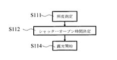
図示しない露光用光源を出た光は、照明光学系11を通り、レティクル12上のマスクパターンを、投影光学系14を介してウェーハ16に投影露光する。ウェーハステージ15の上あるいはその近傍には照度モニタ17が設けられ、その検出値を照度制御部18に出力して照度の制御を行うとともに、実露光時間(シャッターオープン時間)が決定される。
Light emitted from an exposure light source (not shown) passes through the illumination
図8は、実露光時間を決定するためのアルゴリズムを表すフローチャートである。即ち、ステップS111において、照度モニタ17によりウェーハ16に照射される光の照度を測定する。次に、ステップS112において、このモニタ値に基づき、シャッターを開状態とする時間(シャッターオープン時間)を決定する。すなわち、適正な露光が得られるように露光時間を決定する。しかる後に、ステップS113において、シャッターを開けて露光を開始する。このようにして、ウェーハ16に照射される光の照度に応じた適正な露光が実現できる。
FIG. 8 is a flowchart showing an algorithm for determining the actual exposure time. That is, in step S111, the illuminance of the light irradiated onto the
ところで、近年の半導体集積回路のパターンのデザインルールの微細化に伴い、露光波長の短波長化が進んでいる。現在主流となっている光源は、波長は248nmのKrF(クリプトン・フッ素)エキシマレーザであり、その次には、波長193nmのArF(アルゴン・フッ素)エキシマレーザが続いている。そして、ArFエキシマレーザの次には、F2(フッ素)レーザ(波長157nm)が候補として挙げられる。 By the way, with the recent miniaturization of design rules for patterns of semiconductor integrated circuits, the exposure wavelength has been shortened. The currently mainstream light source is a KrF (krypton / fluorine) excimer laser with a wavelength of 248 nm, followed by an ArF (argon / fluorine) excimer laser with a wavelength of 193 nm. Next to the ArF excimer laser, an F2 (fluorine) laser (wavelength 157 nm) is listed as a candidate.
F2(フッ素)レーザ(波長157nm)を用いた投影露光装置としては、ウェーハ16に塗布されたレジストからのアウトガスによる対物レンズの汚染を、酸素と紫外光とにより除去する技術が開示されている(非特許文献1)。
ところが、F2レーザ光は、大気中の酸素や水分によって吸収されてしまうため、その照射空間を、窒素やヘリウム等の不活性ガスによるパージする必要がある。つまり、投影露光装置の照明光学系11、レティクル支持台13、投影光学系14などの空間を、窒素やヘリウムなどの不活性ガスによりパージする必要がある。
However, since the F2 laser light is absorbed by oxygen and moisture in the atmosphere, it is necessary to purge the irradiation space with an inert gas such as nitrogen or helium. In other words, it is necessary to purge the spaces such as the illumination
ところが、本発明者の検討の結果、このようにして不活性ガスによるパージを行っても、ウェーハ16に対する適正な露光量に「ばらつき」が生ずるという問題があることが分かった。そして、その原因を調べた結果、レティクル(フォトマスク)12の表面に、装置外部からの有機物や無機物などのコンタミ(汚染物質)や、装置内部の構造物からの汚染物質が付着するために透過率が低下し、露光中に透過率が変化してしまうためであることが判明した。このような汚染物質は、例えば、レティクルを専用ケースに装填する時や、運搬・保管時などに付着することがある。
However, as a result of the study by the present inventor, it has been found that there is a problem that “variation” occurs in an appropriate exposure amount for the
本発明は、かかる課題の認識に基づいてなされたものであり、その目的は、レティクルに付着した汚染物質などによる露光量の「ばらつき」を防ぐことができる投影露光装置及び投影露光方法を提供することにある。 The present invention has been made on the basis of recognition of such a problem, and an object thereof is to provide a projection exposure apparatus and a projection exposure method capable of preventing “variation” of an exposure amount due to a contaminant attached to a reticle. There is.
上記目的を達成するため、本発明によれば、露光開始前に、レティクル支持台を所定の活性ガスを含む不活性ガスからなるパージガスで満たし、一定の光ビーム照射を行うことにより、汚染物質により低下したレティクルの透過率を回復させたのち、実露光時間をもとめて露光を実施する。このようにすれば、レティクルの露光中における透過率変化による線幅の「ばらつき」を抑制し、線幅の制御性を向上させることができる。 In order to achieve the above object, according to the present invention, before the start of exposure, the reticle support table is filled with a purge gas composed of an inert gas containing a predetermined active gas, and a constant light beam irradiation is performed, thereby causing contamination by contaminants. After recovering the lowered transmittance of the reticle, the exposure is performed for the actual exposure time. In this way, the “variation” of the line width due to the change in transmittance during the exposure of the reticle can be suppressed, and the controllability of the line width can be improved.
すなわち、本発明の投影露光装置は、光源と、光学系と、レティクルを保持可能としたレティクルステージと、前記レティクルの周囲を活性ガスを含む雰囲気に維持可能とするガス供給手段と、前記レティクルの透過率の変化を測定可能とした透過率測定手段と、ウェーハを載置可能としたウェーハステージと、を備え、
前記ガス供給手段により前記レティクルの周囲の雰囲気を前記活性ガスを含む雰囲気に維持しつつ前記光源から前記レティクルに光を照射することにより前記レティクルに付着した汚染物質を除去する光洗浄を実施可能としたことを特徴とする。
That is, the projection exposure apparatus of the present invention includes a light source, an optical system, a reticle stage capable of holding a reticle, a gas supply means capable of maintaining the periphery of the reticle in an atmosphere containing an active gas, and the reticle A transmittance measuring means capable of measuring a change in transmittance, and a wafer stage capable of mounting a wafer,
Light cleaning can be performed to remove contaminants attached to the reticle by irradiating light onto the reticle from the light source while maintaining the atmosphere around the reticle by the gas supply means in an atmosphere containing the active gas. It is characterized by that.
ここで、前記ウェーハに照射される光の照度を測定する照度センサと、前記照度センサにより測定された照度から、前記ウェーハに対する露光時間を決定する制御機構と、をさらに備え、前記制御機構は、前記光洗浄の後に前記露光時間の決定を行うものとすることができる。 Here, an illuminance sensor that measures the illuminance of light irradiated on the wafer, and a control mechanism that determines an exposure time for the wafer from the illuminance measured by the illuminance sensor, the control mechanism comprises: The exposure time may be determined after the light cleaning.
また、前記レティクルの周囲の雰囲気における前記活性ガスの濃度を測定する濃度測定機構と、前記濃度測定機構の出力に応じて前記活性ガスの濃度を制御する濃度制御機構と、をさらに備えたものとすることができる。 A concentration measuring mechanism for measuring the concentration of the active gas in the atmosphere around the reticle; and a concentration control mechanism for controlling the concentration of the active gas according to the output of the concentration measuring mechanism; can do.
また、前記活性ガスは、O2、O3、CO2、CO、酸化窒素類(NOX)、酸化硫黄類(SOX)及び酸素を含む有機ガスよりなる群から選択された少なくともいずれかであるものとすることができる。 The active gas may be at least one selected from the group consisting of O 2 , O 3 , CO 2 , CO, nitric oxides (NO X ), sulfur oxides (SO X ), and oxygen. There can be.
また、前記活性ガスを含む雰囲気は、前記活性ガスと不活性ガスとを含み、前記不活性ガスは、N2、Ar及びHeよりなる群から選択されたいずれかであるものとすることができる。 The atmosphere containing the active gas includes the active gas and an inert gas, and the inert gas may be any selected from the group consisting of N 2 , Ar, and He. .
また、前記透過率測定手段により測定された前記透過率の変化が所定値を下回ると前記光洗浄を停止することができる。 Further, when the change in the transmittance measured by the transmittance measuring means falls below a predetermined value, the optical cleaning can be stopped.
また、前記透過率測定手段は、前記レティクルに設けられた透過率測定用窓の部分において前記透過率の測定を行うものとすることができる。 The transmittance measuring means may measure the transmittance at a portion of a transmittance measuring window provided on the reticle.
また、前記光源は、F2レーザ光を放出するものとすることができる。 The light source may emit F2 laser light.
一方、本発明の投影露光方法は、レティクルの周囲の雰囲気を活性ガスを含む雰囲気に維持しつつ前記レティクルに光を照射することにより前記レティクルに付着した汚染物質を除去する光洗浄を、前記レティクルの透過率の変化が所定値以下になるまで実施する第1の工程と、前記レティクルを介してウェーハに光を照射することにより露光を実施する第2の工程と、を備えたことを特徴とする。 On the other hand, in the projection exposure method of the present invention, the reticle is subjected to optical cleaning for removing contaminants attached to the reticle by irradiating the reticle with light while maintaining the atmosphere around the reticle in an atmosphere containing an active gas. And a second step of performing exposure by irradiating the wafer with light through the reticle, and a second step of performing exposure by irradiating the wafer with light through the reticle. To do.
ここで、前記活性ガスを含む雰囲気における前記活性ガスの濃度は、500ppm以下であるものとすることができる。 Here, the concentration of the active gas in the atmosphere containing the active gas may be 500 ppm or less.
また、前記光洗浄の後であって、前記ウェーハに対する露光を実施する前に、前記レティクルの周囲の雰囲気に含まれる前記活性ガスを除去するために、不活性ガスによるパージを実施するものとすることができる。 In addition, purging with an inert gas is performed to remove the active gas contained in the atmosphere around the reticle after the light cleaning and before the exposure of the wafer. be able to.
本発明によれば、レティクルを専用ケースに装填時や運搬・保管時などに付着する外部からの有機物や無機物の汚染物質や、投影露光装置の内部の構造物から付着する汚染物質などにより、レティクル支持台200のレティクル表面の透過率が低下し、露光中にレティクルの透過率が変化してしまい線幅が変化する問題を防止することができる。 According to the present invention, the reticle is caused by organic contaminants or inorganic contaminants adhering to the reticle when it is loaded into the special case, transporting or storing, or contaminants adhering to the structure inside the projection exposure apparatus. It is possible to prevent the problem that the transmittance of the reticle surface of the support table 200 is lowered, the transmittance of the reticle is changed during exposure, and the line width is changed.
その結果として、F2レーザ光のように短波長の光を用いた微細加工を安定して実施することができ、高集積度且つ高性能の半導体装置などを安定的に製造することが可能となり、産業上のメリットは多大である。 As a result, it is possible to stably carry out microfabrication using short-wavelength light such as F2 laser light, and to stably manufacture highly integrated and high-performance semiconductor devices, There are significant industrial benefits.
以下、本発明の実施の形態について、図面を参照しつつ詳細に説明する。
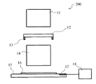
図1は、本発明の実施の形態にかかる投影露光装置の要部構成を表す模式図である。
すなわち、本実施形態の投影露光装置100は、露光用光源1、照明光学系11、レティクルステージ30、投影光学系14及びウェーハステージ15を備える。レティクルステージ30にはレティクル支持台13が設けられ、レティクル(フォトマスク)12が載置される。また、ウェーハステージ15の上には、半導体ウェーハ16が載置される。
Hereinafter, embodiments of the present invention will be described in detail with reference to the drawings.
FIG. 1 is a schematic diagram showing a main configuration of a projection exposure apparatus according to an embodiment of the present invention.
That is, the
露光用光源1を出た光は、照明光学系11を通り、レティクル12上のマスクパターンを、投影光学系14を介してウェーハ16に投影露光する。ウェーハステージ15の上あるいはその近傍には照度モニタ17が設けられ、その検出値を照度制御部18に出力して照度の制御を行うとともに、実露光時間(シャッターオープン時間)が決定される。
The light emitted from the
そしてさらに、本実施形態の投影露光装置では、レティクルステージ30において、所定量の活性ガスを含む不活性ガスからなるパージガスで満たされた空間が形成可能とされ、さらに、このパージガスを満たした状態で一定量の露光光を照射することができる。
Furthermore, in the projection exposure apparatus of the present embodiment, a space filled with a purge gas made of an inert gas containing a predetermined amount of active gas can be formed in the
このために、レティクルステージ30には、流量調節機構19、パージガス供給口20、パージガス回収口21、透過率測定機22及び酸素濃度測定機構23が設けられている。すなわち、パージガス供給口20を介して、活性ガスを含有する不活性ガスをレティクルステージ30に供給することができる。
For this purpose, the
ここで、活性ガスとしては、酸素(O)を含有したガスを用いることができる。具体的には、活性ガスとして、O2、O3、CO2、CO、酸化窒素類(NOX)、酸化硫黄類(SOX)、その他、酸素を含む各種の有機ガスの少なくともいずれかを用いることができる。一方、不活性ガスとしては、N2、Ar、Heの希ガスのいずれかを用いることができる。また、活性ガスの濃度は、後に詳述するように、500ppm以下とするとよい。 Here, a gas containing oxygen (O) can be used as the active gas. Specifically, at least one of O 2 , O 3 , CO 2 , CO, nitric oxides (NO X ), sulfur oxides (SO X ), and other various organic gases containing oxygen is used as the active gas. Can be used. On the other hand, as the inert gas, any of noble gases of N 2 , Ar, and He can be used. The concentration of the active gas is preferably 500 ppm or less, as will be described in detail later.
例えば、レティクル12の表面に、有機物CxHyOzが付着している場合の分解除去のメカニズムは、以下のように説明することができる。
すなわち、まず、有機物CxHyOzに対してF2(フッ素)レーザ光(波長157nm)が照射されると、以下の反応が生じ、有機物のラジカルが形成される。
CxHyOz + Hν → CxHyOz *
一方、活性ガスとして酸素が供給された場合には、F2(フッ素)レーザ(波長157nm)の照射によって、以下の分解が生ずる。
O2 + Hν → O + O
このようにして形成された原子状酸素は、O2ガスと結合してオゾン(O3)を形成する。
For example, the mechanism of decomposition and removal when the organic substance C x H y O z adheres to the surface of the
That is, first, when the organic substance C x H y O z is irradiated with F2 (fluorine) laser light (wavelength 157 nm), the following reaction occurs, and an organic radical is formed.
C x H y O z + Hν → C x H y O z *
On the other hand, when oxygen is supplied as the active gas, the following decomposition occurs by irradiation with an F2 (fluorine) laser (wavelength 157 nm).
O 2 + Hν → O + O
The atomic oxygen thus formed is combined with O 2 gas to form ozone (O 3 ).
O + O2 → O3
このオゾンは、F2(フッ素)レーザ(波長157nm)の照射によって、酸素ラジカル(O*)を形成する。
O3 + Hν → O2 + O*
このようにして形成された酸素ラジカルは、有機物のラジカルと反応し、平衡蒸気圧の高いガス成分に分解する。
CxHyOz * + O* → CO、CO2、H2O
このようにして分解されたガス成分は、レティクル12の表面から脱離して除去される。すなわち、酸素を含むガス雰囲気において、光を照射することにより、有機物をいわゆる「アッシング(ashing:灰化)」させて分解除去することができる。
O + O 2 → O 3
This ozone forms oxygen radicals (O * ) by irradiation with an F2 (fluorine) laser (wavelength 157 nm).
O 3 + Hν → O 2 + O *
The oxygen radicals thus formed react with organic radicals and decompose into gas components having a high equilibrium vapor pressure.
C x H y O z * + O * → CO, CO 2, H 2 O
The gas component decomposed in this manner is desorbed from the surface of the
以上説明したように、露光開始前に、このような活性ガスを含む不活性ガスからなるパージガスでレティクル12を包む空間を満たし、一定の光ビーム照射を行うことにより、レティクル12の表面に付着した汚染物質を分解して除去し、その透過率を回復させることができる。
As described above, before the exposure is started, the space enclosing the
その際に、レティクル12の透過率を透過率測定機22により測定して、その結果をフィードバックすることができる。透過率測定器22は、例えば、レティクル12に入射する光の強度を測定する1次光測定器22aと、レティクル12を透過した光の強度を測定する2次光測定器22bと、を有する。1次光測定器22aと2次光測定器22bとの測定結果を比較することにより、レティクル12の透過率を決定できる。
At that time, the transmittance of the
また、レティクルステージ30内に満たされたパージガス中の活性ガスの濃度は、酸素濃度測定機構23によりモニタされ、酸素濃度測定機構23の出力に応じて、マスフローコントローラなどの流量調節機構19を制御して、酸素の濃度を制御できるようにされている。
Further, the concentration of the active gas in the purge gas filled in the
このようにしてレティクル12の透過率を回復させた後、ウェーハステージ15の上に設けられた照度モニター17により実露光時間(シャッターオープン時間)を求めて、露光を行なうことができる。
After recovering the transmittance of the
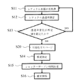
図2は、本実施形態の投影露光装置において露光時間を決定するアルゴリズムを表すフローチャートである。
まず、ステップS11において、レティクル12の表面を光洗浄する。すなわち、活性ガスを含むガスによりレティクルステージ30をパージし、所定の量の光を照射することにより、レティクル12の表面に付着した有機物や無機物などの汚染物質を分解して除去する。
FIG. 2 is a flowchart showing an algorithm for determining the exposure time in the projection exposure apparatus of this embodiment.
First, in step S11, the surface of the
次に、ステップS12において、レティクル12の透過率を測定する。すなわち、透過率測定器22(22a、22b)を用いて、レティクル12の光の透過率を測定する。
Next, in step S12, the transmittance of the
次に、ステップS13において、レティクル12の透過率の変化が所定量を超えるか否かを判定する。すなわち、光洗浄によって、レティクル12の透過率がある程度向上する場合には、レティクル12の表面に、除去可能な汚染物質がまだ残存している可能性が高い。このため、レティクル12の透過率の変化量に基づいて、さらなる光洗浄が必要であるか否かを判定する。この場合の、透過率の変化量の判断基準は、例えば、0.1パーセントとすることができる。
Next, in step S13, it is determined whether or not the change in transmittance of the
透過率の変化量が所定量(例えば、0.1パーセント)を超える場合には、ステップS11に戻り、光洗浄を実施する。
一方、透過率の変化量が所定量(例えば、0.1パーセント)以下である場合には、再度の光洗浄は不要であると判断して、ステップS14に進み、照度を測定する。すなわち、ウェーハステージ15に設けられた照度モニタ17によって、ウェーハ16に照射される光の照度を測定する。
次に、ステップS15において、この測定値に基づき、シャッターを開状態とする時間(シャッターオープン時間)を決定する。すなわち、適正な露光が得られるように露光時間を決定する。しかる後に、ステップS16において、シャッターを開けて露光を開始する。このようにして、ウェーハ16に照射される光の照度に応じた適正な露光が実現できる。
When the change amount of the transmittance exceeds a predetermined amount (for example, 0.1%), the process returns to step S11 to perform light cleaning.
On the other hand, when the amount of change in transmittance is equal to or less than a predetermined amount (for example, 0.1%), it is determined that re-light cleaning is not necessary, and the process proceeds to step S14 to measure illuminance. That is, the illuminance of light irradiated on the
Next, in step S15, based on this measurement value, a time for opening the shutter (shutter open time) is determined. That is, the exposure time is determined so that proper exposure can be obtained. Thereafter, in step S16, the shutter is opened and exposure is started. In this manner, appropriate exposure according to the illuminance of the light irradiated on the
また、このようにして露光を開始する時点では、レティクル12に付着した有機物や無機物の汚染物質は十分に洗浄されているので、ウェーハ16に対する露光中にレティクル12の表面の汚染物質がさらに除去されて、露光量が適正値からずれるという問題も防ぐことができる。
Further, at the time of starting exposure in this way, the organic and inorganic contaminants adhering to the
図3(a)及び(b)は、本発明における光洗浄の効果を例示するグラフ図である。 すなわち、図3(a)の横軸は、レティクル12に対して光を照射した時間を表し、縦軸は、レティクル12の透過率を表す。なおここで、光の波長は157ナノメータ、照射エネルギーは120ミリワット(1000ヘルツ)、照射エネルギー密度は0.1mJ/cm2、雰囲気は酸素(O2)と窒素(N2)の混合ガスとし、酸素濃度は10ppm以下とした。
FIGS. 3A and 3B are graphs illustrating the effect of light cleaning in the present invention. That is, the horizontal axis in FIG. 3A represents the time when the
図3(a)から分かるように、光の照射の初期には急激な透過率の上昇が見られ、さらに光を照射すると緩やかに透過率が上昇する。同図の具体例の場合、600秒間の光洗浄によって、レティクルの透過率は、2.5パーセントほど上昇している。本発明者の実験の結果によれば、5パーセント程度の透過率の上昇を得ることも可能であった。 As can be seen from FIG. 3A, a rapid increase in transmittance is observed at the initial stage of light irradiation, and when light is further irradiated, the transmittance gradually increases. In the case of the specific example shown in the figure, the transmittance of the reticle is increased by about 2.5% by light cleaning for 600 seconds. According to the results of experiments by the inventors, it was possible to obtain an increase in transmittance of about 5%.
なお、本発明者の実験によれば、酸素と窒素の混合雰囲気を用いた場合、酸素の濃度を10〜50ppm程度の範囲で高くすることにより、さらに高い洗浄効果が得られることが分かっている。 In addition, according to the experiment by the present inventors, it is known that when a mixed atmosphere of oxygen and nitrogen is used, a higher cleaning effect can be obtained by increasing the oxygen concentration in the range of about 10 to 50 ppm. .
また、図3(b)は、同図(a)に対応して得られたパターンの線幅寸法の変化を表すグラフ図である。なおここで表した線幅は、ポジレジストを用いて形成されたレジストパターンの線幅である。すなわち、レジストに対して光が照射されなかった部分の幅に対応する。また、線幅の目標値は、500ナノメータである。 FIG. 3B is a graph showing the change in the line width dimension of the pattern obtained corresponding to FIG. The line width shown here is the line width of a resist pattern formed using a positive resist. That is, it corresponds to the width of the part where the resist is not irradiated with light. The target value of the line width is 500 nanometers.
図3(b)を見ると、光洗浄前の状態においては、線幅はおよそ850ナノメータであり、目標値の500ナノメータよりも大幅に大きいことが分かる。これは、レティクルの透過率が低いために、レジストに対する露光量が適正値よりも不足したからである。 Referring to FIG. 3B, it can be seen that the line width is about 850 nanometers before the optical cleaning, which is significantly larger than the target value of 500 nanometers. This is because the exposure amount to the resist is less than the appropriate value due to the low transmittance of the reticle.
一方、光洗浄すると、その初期段階において見られるレティクルの透過率の急激な上昇に対応して線幅が急激に低下し、目標値に近づくことが分かる。そして、およそ100秒程度の光洗浄により、線幅は目標値の500ナノメータにほぼ近い値が得られている。すなわち、レティクル表面の透過率の回復に対応して、線幅も安定してしてくる様子が読み取れる。
以上説明したように、本発明によれば、活性ガスを含有した雰囲気中で光洗浄することにより、レティクルに付着した汚染物質を効果的に除去し、透過率を回復することができる。
On the other hand, when light cleaning is performed, it can be seen that the line width sharply decreases and approaches the target value in response to the rapid increase in the transmittance of the reticle seen in the initial stage. Then, by light cleaning for about 100 seconds, the line width is almost close to the target value of 500 nanometers. That is, it can be seen that the line width is stabilized corresponding to the recovery of the transmittance on the reticle surface.
As described above, according to the present invention, the contaminants attached to the reticle can be effectively removed and the transmittance can be recovered by performing optical cleaning in an atmosphere containing an active gas.
いわゆる「半透過系」あるいは「ハーフトーン」などと呼ばれるレティクルの場合、透過率の変動のマージンは数パーセントである。すなわち、レティクルの透過率が数パーセント以上変動すると、形成されるパターンの線幅の「ずれ」が許容範囲を上回る場合がある。これに対して、本発明における光洗浄の効果は、このような厳しい要求に対して応ずることができ、その効果は絶大である。 In the case of a so-called “semi-transmissive” or “half-tone” reticle, the margin of variation in transmittance is several percent. That is, if the transmittance of the reticle varies by several percent or more, the “shift” of the line width of the pattern to be formed may exceed the allowable range. On the other hand, the effect of the light cleaning in the present invention can meet such a severe requirement, and the effect is great.
次に、本発明における光洗浄の際の活性ガスの濃度について説明する。
すなわち、本発明者の実験の結果、レティクルステージ30に供給する活性ガスの濃度が低すぎても高すぎても、レティクル12に付着した汚染物質の分解の効果が不足することが分かった。
Next, the concentration of the active gas at the time of light cleaning in the present invention will be described.
That is, as a result of experiments by the present inventor, it has been found that the effect of decomposing contaminants attached to the
活性ガスとして酸素(O2)、不活性ガスとして窒素(N2)を用いた場合の光洗浄の効果を調べた結果は、以下の如くである。
活性ガスの濃度 光洗浄効果
2ppm ×
5ppm △
10ppm ○
100ppm ○
200ppm ○
500ppm ○
700ppm △
2000ppm ×
ここで、光洗浄効果として、「○」で表したものは、レティクルの透過率に5パーセント以上の上昇が得られた場合を表し、「△」で表したものは、レティクルの透過率に1パーセント以上5パーセント未満の上昇が得られた場合を表し、「×」で表したものは、レティクルの透過率に1パーセント未満の上昇しか得られなかったものを表す。
The results of examining the effect of photocleaning when oxygen (O 2 ) is used as the active gas and nitrogen (N 2 ) is used as the inert gas are as follows.
Active gas concentration Light cleaning effect
2ppm ×
5ppm △
10ppm ○
100ppm ○
200ppm ○
500ppm ○
700ppm △
2000ppm ×
Here, as the light cleaning effect, a value represented by “◯” represents a case where an increase of 5% or more was obtained in the transmittance of the reticle, and a value represented by “Δ” represents 1 in the transmittance of the reticle. A case where an increase of not less than 5 percent and less than 5 percent is obtained, and an “x” indicates that the transmittance of the reticle was obtained by less than 1 percent.
酸素の濃度が5ppm以下であると、光洗浄の効果が不足するのは、酸素ラジカルの供給量が不足するからであると考えられる。一方、酸素の濃度が700ppm以上の場合に光洗浄の効果が不足するのは、F2(フッ素)レーザ(波長157nm)光がパージガスにより吸収され、レティクル12の表面に十分に達しないからであると考えられる。
If the oxygen concentration is 5 ppm or less, it is considered that the effect of photocleaning is insufficient because the supply amount of oxygen radicals is insufficient. On the other hand, when the concentration of oxygen is 700 ppm or more, the effect of photocleaning is insufficient because F2 (fluorine) laser (wavelength 157 nm) light is absorbed by the purge gas and does not reach the surface of the
以上の結果から、本発明におけるパージガス中の活性ガスの濃度は、5ppm以上で700ppm以下であることが望ましく、10ppm以上で500ppm以下であることがさらに望ましいといえる。 From the above results, it can be said that the concentration of the active gas in the purge gas in the present invention is preferably 5 ppm or more and 700 ppm or less, more preferably 10 ppm or more and 500 ppm or less.
図4は、本発明の変型例の投影露光装置を表す模式図である。同図については、図1乃至図3に関して前述したものと同様の要素には同一の符号を付して詳細な説明は省略する。 FIG. 4 is a schematic view showing a projection exposure apparatus according to a modification of the present invention. In this figure, the same elements as those described above with reference to FIGS. 1 to 3 are denoted by the same reference numerals, and detailed description thereof is omitted.
本変型例においては、露光用光源1の出力に光出力モニタ25が設けられ、また、ウェーハステージ15の上あるいはウェーハ16の近傍に、透過率モニタ22cが設けられている。
In this modification, a light output monitor 25 is provided at the output of the exposure
光洗浄の効果を評価するためには、レティクル12の透過率の変化を測定する必要がある。これに対して、本変型例においては、光出力モニタ25によりレティクル12に入射する1次光の強度に対応する量を測定し、一方、ウェーハ16の近傍に設けられた透過率モニタ22cによってレティクル12を透過した光の強度に対応する量を測定する。レティクル12の透過率は、これらの測定値を比較することにより相対的に評価することができる。
In order to evaluate the effect of light cleaning, it is necessary to measure the change in transmittance of the
図5は、本発明において用いることができるレティクル12の具体例を表す模式図である。すなわち、レティクル12に設けられるパターン形成領域12aは、遮光膜に所定の開口が形成され、この開口形状に応じた露光が可能とされている。しかし、形成するパターンの種類(素子分離パターン、トレンチ形成パターンなど)や、それに用いるレジストの種類(ポジレジスト、ネガレジスト)によっては、パターン形成領域12aの殆どは遮光膜により覆われ、光を透過する開口が僅かにしか形成されない場合もある。このような場合には、レティクル12の透過率を測定することが容易ではない。
FIG. 5 is a schematic diagram showing a specific example of the
そこで、透過率の測定を確実且つ容易に実施するため、レティクル12の一部に、遮光膜を除去した透過率測定用の窓領域12bを設けるとよい。このようにすれば、感度の低いセンサを用いた場合や、図4に関して前述したように、ウェーハ16の近傍に透過率モニタ22cを設けた場合などにおいても、レティクル12の透過率の変化を確実且つ容易に検出することができる。
Therefore, in order to reliably and easily measure the transmittance, a transmittance measuring
図6は、本発明の投影露光装置の動作の変型例を表すフローチャート図である。同図については、図1乃至図5に関して前述したものと同様の要素には同一の符号を付して詳細な説明は省略する。 FIG. 6 is a flowchart showing a modified example of the operation of the projection exposure apparatus of the present invention. In this figure, the same elements as those described above with reference to FIGS. 1 to 5 are denoted by the same reference numerals and detailed description thereof is omitted.
本変型例においては、ステップS14における照度測定の前に、ステップS20として、不活性ガスのパージを実施する。すなわち、光洗浄に際しては、レティクルステージ30を活性ガスと不活性ガスの混合ガスによりパージするが、このまま露光を実施すると、活性ガスの濃度によっては、露光光の吸収による損失が生ずる。
In this modified example, an inert gas purge is performed as step S20 before the illuminance measurement in step S14. That is, when cleaning the light, the
そこで、本変型例においては、光洗浄が終了した時点で、活性ガスの供給を停止し、不活性ガスのみによってレティクルステージ30をパージする。こうすることにより、ウェーハ16に対する露光に際して、F2(フッ素)レーザ(波長157nm)光がパージガスにより吸収される損失を防ぐことができ、より短時間で露光を実施できる。
Therefore, in this modification, when the optical cleaning is completed, the supply of the active gas is stopped, and the
以上、具体例を参照しつつ本発明の実施の形態について説明した。しかし、本発明は、これらの具体例に限定されるものではない。 The embodiments of the present invention have been described above with reference to specific examples. However, the present invention is not limited to these specific examples.
例えば、投影露光装置を構成する露光用光源、照明光学系、レティクルステージ、投影光学系及びウェーハステージなどの各要素の具体的な構造やサイズなどについては、前述したもの以外にも当業者が適宜設計したものも、本発明の要旨を含む限り、本発明の範囲に包含される。さらに、活性ガスや不活性ガスの種類、流量、流速分布、あるいはそれらの供給手段や排出手段などについても、当業者が適宜選択して用いたものは本発明の範囲に包含される。 For example, in addition to those described above, those skilled in the art will appropriately determine the specific structure and size of each element such as the exposure light source, illumination optical system, reticle stage, projection optical system, and wafer stage that constitute the projection exposure apparatus. Designed ones are also included in the scope of the present invention as long as they include the gist of the present invention. Furthermore, the types of active gas and inert gas, the flow rate, the flow velocity distribution, or the supply means and discharge means thereof, which are appropriately selected and used by those skilled in the art, are included in the scope of the present invention.
その他、本発明の要素を具備し、当業者が適宜設計変更しうる全ての投影露光装置及び投影露光方法は、本発明の範囲に包含される。 In addition, all projection exposure apparatuses and projection exposure methods that include elements of the present invention and that can be appropriately modified by those skilled in the art are included in the scope of the present invention.
1 露光用光源
11 照明光学系
12 フォトマスク(レティクル)
12a パターン形成領域
12b 窓領域
13 レティクル支持台
14 投影光学系
15 ウェーハステージ
16 ウェーハ
17 照度モニタ
18 照度制御部
19 流量調節機構
20 パージガス供給口
21 パージガス回収口
22 透過率測定機
22a 1次光測定器
22b 2次光測定器
22c 透過率モニタ
23 酸素濃度測定機構
25 光出力モニタ
30 レティクルステージ
100 投影露光装置
200 投影露光装置
DESCRIPTION OF
12a
Claims (11)
光学系と、
レティクルを保持可能としたレティクルステージと、
前記レティクルの周囲を活性ガスを含む雰囲気に維持可能とするガス供給手段と、
前記レティクルの透過率の変化を測定可能とした透過率測定手段と、
ウェーハを載置可能としたウェーハステージと、
を備え、
前記ガス供給手段により前記レティクルの周囲の雰囲気を前記活性ガスを含む雰囲気に維持しつつ前記光源から前記レティクルに光を照射することにより前記レティクルに付着した汚染物質を除去する光洗浄を可能としたことを特徴とする投影露光装置。 A light source;
Optical system,
A reticle stage that can hold the reticle;
Gas supply means capable of maintaining the periphery of the reticle in an atmosphere containing an active gas;
A transmittance measuring means capable of measuring a change in transmittance of the reticle;
A wafer stage on which a wafer can be placed;
With
Light cleaning that removes contaminants attached to the reticle by irradiating light onto the reticle from the light source while maintaining the atmosphere around the reticle by the gas supply means in an atmosphere containing the active gas is enabled. A projection exposure apparatus.
前記照度センサにより測定された照度から、前記ウェーハに対する露光時間を決定する制御機構と、
をさらに備え、前記制御機構は、前記光洗浄の後に前記露光時間の決定を行うことを特徴とする請求項1記載の投影露光装置。 An illuminance sensor for measuring the illuminance of light irradiated on the wafer;
A control mechanism for determining an exposure time for the wafer from the illuminance measured by the illuminance sensor;
The projection exposure apparatus according to claim 1, further comprising: determining the exposure time after the light cleaning.
前記濃度測定機構の出力に応じて前記活性ガスの濃度を制御する濃度制御機構と、
をさらに備えたことを特徴とする請求項1または2に記載の投影露光装置。 A concentration measuring mechanism for measuring the concentration of the active gas in the atmosphere around the reticle;
A concentration control mechanism for controlling the concentration of the active gas according to the output of the concentration measurement mechanism;
The projection exposure apparatus according to claim 1, further comprising:
前記不活性ガスは、N2、Ar及びHeよりなる群から選択されたいずれかであることを特徴とする請求項1〜4のいずれか1つに記載の投影露光装置。 The atmosphere containing the active gas includes the active gas and an inert gas,
The projection exposure apparatus according to claim 1, wherein the inert gas is one selected from the group consisting of N 2 , Ar, and He.
前記レティクルを介してウェーハに光を照射することにより露光を実施する第2の工程と、
を備えたことを特徴とする投影露光方法。 Light cleaning that removes contaminants attached to the reticle by irradiating the reticle with light while maintaining the atmosphere around the reticle in an atmosphere containing an active gas causes the change in the transmittance of the reticle to fall below a predetermined value. A first step to be carried out until
A second step of performing exposure by irradiating the wafer with light through the reticle;
A projection exposure method comprising:
Purging with an inert gas is performed to remove the active gas contained in the atmosphere around the reticle after the light cleaning and before the exposure of the wafer. The projection exposure method according to claim 9 or 10.
Priority Applications (1)
| Application Number | Priority Date | Filing Date | Title |
|---|---|---|---|
| JP2003428758A JP2005191166A (en) | 2003-12-25 | 2003-12-25 | Projection aligner and projection exposure method |
Applications Claiming Priority (1)
| Application Number | Priority Date | Filing Date | Title |
|---|---|---|---|
| JP2003428758A JP2005191166A (en) | 2003-12-25 | 2003-12-25 | Projection aligner and projection exposure method |
Publications (2)
| Publication Number | Publication Date |
|---|---|
| JP2005191166A true JP2005191166A (en) | 2005-07-14 |
| JP2005191166A5 JP2005191166A5 (en) | 2006-04-27 |
Family
ID=34787622
Family Applications (1)
| Application Number | Title | Priority Date | Filing Date |
|---|---|---|---|
| JP2003428758A Pending JP2005191166A (en) | 2003-12-25 | 2003-12-25 | Projection aligner and projection exposure method |
Country Status (1)
| Country | Link |
|---|---|
| JP (1) | JP2005191166A (en) |
Cited By (2)
| Publication number | Priority date | Publication date | Assignee | Title |
|---|---|---|---|---|
| JP2008078642A (en) * | 2006-08-28 | 2008-04-03 | Interuniv Micro Electronica Centrum Vzw | Method and system for measuring contamination of lithography component |
| JP2014207479A (en) * | 2009-08-07 | 2014-10-30 | 株式会社ニコン | Exposure device, exposure method, and device manufacturing method |
-
2003
- 2003-12-25 JP JP2003428758A patent/JP2005191166A/en active Pending
Cited By (3)
| Publication number | Priority date | Publication date | Assignee | Title |
|---|---|---|---|---|
| JP2008078642A (en) * | 2006-08-28 | 2008-04-03 | Interuniv Micro Electronica Centrum Vzw | Method and system for measuring contamination of lithography component |
| JP2014207479A (en) * | 2009-08-07 | 2014-10-30 | 株式会社ニコン | Exposure device, exposure method, and device manufacturing method |
| JP5618261B2 (en) * | 2009-08-07 | 2014-11-05 | 株式会社ニコン | Exposure apparatus and device manufacturing method |
Similar Documents
| Publication | Publication Date | Title |
|---|---|---|
| JP2000323396A (en) | Exposure method, aligner, and manufacture thereof | |
| JP2003188096A (en) | Lithographic projection apparatus, device manufacturing method, device manufactured thereby, cleaning unit and method of cleaning contaminated object | |
| US20080241711A1 (en) | Removal and prevention of photo-induced defects on photomasks used in photolithography | |
| TW200302956A (en) | Inert gas purge method and apparatus, exposure apparatus, reticle stocker, reticle inspection apparatus, reticle transfer box, and device manufacturing method | |
| JP2005244015A (en) | Aligner, optical cleaning method of optical element in aligner, and process for fabricating device having fine pattern | |
| JP2005191166A (en) | Projection aligner and projection exposure method | |
| JP2011171620A (en) | Exposure device, cleaning method, and method of manufacturing the device | |
| JP2004259828A (en) | Semiconductor exposure system | |
| JP3619157B2 (en) | Optical element, exposure apparatus having the optical element, cleaning apparatus, and optical element cleaning method | |
| JP2003344601A (en) | Device and method for cleaning optical element and method for manufacturing it | |
| US8568959B2 (en) | Techniques for reducing degradation and/or modifying feature size of photomasks | |
| KR101253948B1 (en) | Method of fabricating photomasks and device for implementing it | |
| JP2005136423A (en) | Lithographic apparatus and method of manufacturing device | |
| JP2006339346A (en) | Exposure device | |
| US20060012762A1 (en) | Method for cleaning semiconductor device | |
| JP3712706B2 (en) | Exposure apparatus and exposure apparatus cleaning method | |
| US20240094646A1 (en) | Exposure apparatus and decontamination apparatus | |
| JP2005142488A (en) | Aligner and method for exposure | |
| JP2005085775A (en) | Method and device for cleaning exposing optical path of aligner | |
| JP2006147639A (en) | Exposure apparatus | |
| JP3483861B2 (en) | Photomask unit, photomask apparatus, projection exposure apparatus, projection exposure method, and semiconductor device | |
| KR100779371B1 (en) | Apparatus for preventing haze defect of reticle using arf laser | |
| US7244346B2 (en) | Concentration measuring mechanism, exposure apparatus, and device production method | |
| EP1710623A1 (en) | Method of cleaning a substrate surface from a crystal nucleus | |
| JP2005057075A (en) | Optical apparatus |
Legal Events
| Date | Code | Title | Description |
|---|---|---|---|
| A711 | Notification of change in applicant |
Free format text: JAPANESE INTERMEDIATE CODE: A711 Effective date: 20050513 |
|
| A521 | Written amendment |
Free format text: JAPANESE INTERMEDIATE CODE: A821 Effective date: 20050513 |
|
| A521 | Written amendment |
Free format text: JAPANESE INTERMEDIATE CODE: A523 Effective date: 20060313 |
|
| A621 | Written request for application examination |
Free format text: JAPANESE INTERMEDIATE CODE: A621 Effective date: 20060313 |
|
| A977 | Report on retrieval |
Free format text: JAPANESE INTERMEDIATE CODE: A971007 Effective date: 20081127 |
|
| A131 | Notification of reasons for refusal |
Free format text: JAPANESE INTERMEDIATE CODE: A131 Effective date: 20081201 |
|
| A02 | Decision of refusal |
Free format text: JAPANESE INTERMEDIATE CODE: A02 Effective date: 20090327 |