JP2005190860A - Electric connector - Google Patents
Electric connector Download PDFInfo
- Publication number
- JP2005190860A JP2005190860A JP2003431701A JP2003431701A JP2005190860A JP 2005190860 A JP2005190860 A JP 2005190860A JP 2003431701 A JP2003431701 A JP 2003431701A JP 2003431701 A JP2003431701 A JP 2003431701A JP 2005190860 A JP2005190860 A JP 2005190860A
- Authority
- JP
- Japan
- Prior art keywords
- arm
- connector
- latch
- squib
- lock member
- Prior art date
- Legal status (The legal status is an assumption and is not a legal conclusion. Google has not performed a legal analysis and makes no representation as to the accuracy of the status listed.)
- Ceased
Links
Images

Classifications
-
- H—ELECTRICITY
- H01—ELECTRIC ELEMENTS
- H01R—ELECTRICALLY-CONDUCTIVE CONNECTIONS; STRUCTURAL ASSOCIATIONS OF A PLURALITY OF MUTUALLY-INSULATED ELECTRICAL CONNECTING ELEMENTS; COUPLING DEVICES; CURRENT COLLECTORS
- H01R13/00—Details of coupling devices of the kinds covered by groups H01R12/70 or H01R24/00 - H01R33/00
- H01R13/62—Means for facilitating engagement or disengagement of coupling parts or for holding them in engagement
- H01R13/627—Snap or like fastening
- H01R13/6271—Latching means integral with the housing
- H01R13/6273—Latching means integral with the housing comprising two latching arms
-
- H—ELECTRICITY
- H01—ELECTRIC ELEMENTS
- H01R—ELECTRICALLY-CONDUCTIVE CONNECTIONS; STRUCTURAL ASSOCIATIONS OF A PLURALITY OF MUTUALLY-INSULATED ELECTRICAL CONNECTING ELEMENTS; COUPLING DEVICES; CURRENT COLLECTORS
- H01R13/00—Details of coupling devices of the kinds covered by groups H01R12/70 or H01R24/00 - H01R33/00
- H01R13/62—Means for facilitating engagement or disengagement of coupling parts or for holding them in engagement
- H01R13/639—Additional means for holding or locking coupling parts together, after engagement, e.g. separate keylock, retainer strap
Abstract
Description
本発明は、スクイブと称するエアバック用のガス充填装置に接続するためのコネクタに関し、特にコネクタ接続を固定するロック部材を有する電気コネクタに関するものである。 The present invention relates to a connector for connecting to a gas filling device for an airbag called a squib, and more particularly to an electrical connector having a lock member for fixing the connector connection.
従来技術として、スクイブとの嵌合をより強固に固定するため、ロック部材をコネクタ筐体に挿入してコネクタの嵌合を補強することは公知である。この種のコネクタは、特に、自動車用エアバックの空気充填装置を作動させる発火装置への電気接続を保証するコネクタにおいて用いられることが多い。受容側のコネクタは一定の形状に定められており、挿入側の代表的なコネクタとしては、特許文献1にも記載されているようなコネクタ筐体が挙げられる。当該コネクタは、電気接続の際には嵌合方向、つまり、電気接触子との電気接続をなす方向と直交方向に電線が延在して前記コネクタ筐体内に収容されている。該コネクタ接続の嵌合部は、コネクタ筐体がスクイブのキャビティ内の係止部で係止されて収容される。
As a prior art, in order to more firmly fix the fitting with the squib, it is known to insert a lock member into the connector housing to reinforce the fitting of the connector. This type of connector is often used, in particular, in a connector that ensures an electrical connection to the ignition device that activates the air filling device of the automotive airbag. The connector on the receiving side is defined in a certain shape, and a typical connector on the insertion side includes a connector housing as described in
また、特許文献2では、スクイブとの嵌合部は、コネクタ筐体と該コネクタ筐体に実装されたロック部材を具備し、該ロック部材は、コネクタ嵌合面に向いた自由端に延びる片持ち梁状に設けられたアームを具備し、該アームの自由端は、嵌合の際にコネクタ筐体に画成された嵌合面近傍で突出したテーパ面に沿って摺動しつつ外側に偏倚して前記コネクタ嵌合面においてスクイブのラッチ部と係止する。よって、前記アームは外側に弾性的に偏倚して前記自由端はスクイブの収容部に収容されて挿入及び引き抜き方向に対してロック部を形成する。
In
前記特許文献2における構造は、ロック部材を押下して前記自由端をテーパ面に摺動させる力に抗するため、高い挿入力が必要となる。また、電線が様々な方向、特に延在方向に対して垂直方向に引張られると係止部が外力を受け、当該係止部が変形又は破損する可能性がある。また、この従来技術による構造以外にも産業上で他形態のロック部材を用いたコネクタ構造が求められている。
Since the structure in
よって、本発明は、上記構造以外にもロック部材を用いて低挿入力でスクイブとの嵌合を固定又はロックし、外力に対する当該嵌合部分の変形又は破損を防止する構造のコネクタを提供する。 Therefore, the present invention provides a connector having a structure that uses a lock member in addition to the above structure to fix or lock the fitting with the squib with a low insertion force and prevent deformation or breakage of the fitting portion with respect to external force. .
本発明の好ましい実施形態によれば、本発明のコネクタは、スクイブに嵌合して電気接続を達成する電気コネクタであって、ロック部材とコネクタ筐体を含み、
前記ロック部材は、前記スクイブと係合可能なラッチ面を有する一対の平行に延びる第1アームと、前記第1アームと平行な一対の第2アームとを有し、
前記コネクタ筐体は、前記スクイブと係合可能なラッチ面を有する、前記第1アームと平行に延びる一対の第3ラッチアームと、前記ロック部材が摺動可能な摺動面と、前記第1ラッチアームの自由端を載置可能な突出部とを有し、
前記ロック部材がロック解除位置からロック完了位置まで前記コネクタ筐体に沿って摺動したときに、前記各第1ラッチアームは互いに対向方向に弾性変形して前記スクイブとの係合を可能にし、ロック位置では前記第1ラッチアームの自由端が前記コネクタ筐体の突出部に載置されると同時に、前記第2アームは前記摺動可能な面と第3アームとの間に挿入される。
According to a preferred embodiment of the present invention, the connector of the present invention is an electrical connector that fits into a squib to achieve electrical connection, and includes a lock member and a connector housing.
The lock member includes a pair of parallel extending first arms having a latch surface engageable with the squib, and a pair of second arms parallel to the first arm,
The connector housing has a latch surface that can be engaged with the squib, a pair of third latch arms extending in parallel with the first arm, a sliding surface on which the lock member can slide, and the first A protrusion on which the free end of the latch arm can be placed;
When the locking member slides along the connector housing from the unlocking position to the locking completion position, the first latch arms are elastically deformed in opposite directions to enable engagement with the squib, In the locked position, the free end of the first latch arm is placed on the protruding portion of the connector housing, and at the same time, the second arm is inserted between the slidable surface and the third arm.
例えば、コネクタ筐体がスクイブと嵌合する弾性変形可能な第3アームを有し、ロック部材がスクイブと嵌合する弾性変形可能な第1アームと前記第3アームの弾性変形を規制する第2アームとを有する構造において、第1アームがコネクタ挿入方向に移動すると同時に、第3アームが弾性変位可能なコネクタ筐体との間隔に第2アームを介在させて該第3アームの弾性変形を規制する構造が提供されれば、第3アームをスクイブと嵌合した状態で固定又はロックすることができる。また、当該構造における第1アームの挿入動作を説明すると、第1アームがスクイブと協働して弾性変形して内側に偏倚しながら係合部で復元し、その後、ロック部材をさらに押圧して第1アームの自由端と筐体の一部とを該第1アームが内倚しないように当接させることにより、第1アームの弾性変形を規制して固定させる。
以上のように、第1アームが固定され、また、第2アームも固定されて、第3アームは弾性変形が阻止されてコネクタ嵌合が固定又はロックされる。本構造の利点は、第1アームが特許文献2のように第1アームを偏倚させた状態でロックする構造より低挿入力でコネクタ嵌合をロックすることができる点であり、強固なコネクタ接続を実現することができる。
For example, the connector housing has an elastically deformable third arm that fits into the squib, and the lock member restricts the elastic deformation of the first arm and the third arm that fits into the squib. In the structure having the arm, the first arm moves in the connector insertion direction, and at the same time, the second arm is interposed in the space between the elastically displaceable connector housing and the elastic deformation of the third arm is restricted. If the structure which performs is provided, a 3rd arm can be fixed or locked in the state fitted with the squib. Also, the insertion operation of the first arm in the structure will be described. The first arm is elastically deformed in cooperation with the squib and is restored in the engaging portion while being biased inward, and then the lock member is further pressed. The elastic deformation of the first arm is regulated and fixed by bringing the free end of the first arm into contact with a part of the housing so that the first arm does not incur.
As described above, the first arm is fixed, the second arm is also fixed, and the third arm is prevented from elastic deformation and the connector fitting is fixed or locked. The advantage of this structure is that the first arm can lock the connector fitting with a lower insertion force than the structure in which the first arm is locked with the first arm biased as in
本発明のさらに好ましい実施形態によれば、本発明の電気コネクタは、前記第1ラッチアームのラッチ面と、前記各ラッチアームの挿入方向とのなす角度は、前記第3ラッチアームのラッチ面と、前記各ラッチアームの挿入方向とのなす角度より小さい。 According to a further preferred embodiment of the present invention, in the electrical connector of the present invention, the angle formed between the latch surface of the first latch arm and the insertion direction of each latch arm is the latch surface of the third latch arm. Smaller than the angle formed with the insertion direction of each latch arm.
例えば、スクイブとの係合において、コネクタ筐体の第3アームが有する係合面とロック部材の第1アームが有する係合面との各傾斜角を相違させることによりコネクタ挿入方向の距離差として各アームの弾性復元作用の発生時期をずらすことができる。当該距離差をロック部材の第1アームに反映させると、例えば、該第1アームの自由端に当該距離間隔を有する画成部を形成し、スクイブとの嵌合後に完全に弾性復元した第1アームをコネクタ挿入方向にさらに押圧して、当該画成部が所定位置に載置されてコネクタ筐体の一部と弾性変形方向に当接するように構成すれば、該第1アームの弾性変形は規制されて当該第1アームを固定又はロックすることができる。 For example, in the engagement with the squib, the distance difference in the connector insertion direction can be obtained by making the inclination angles of the engagement surface of the third arm of the connector housing different from the engagement surface of the first arm of the lock member. The generation time of the elastic restoring action of each arm can be shifted. When the difference in distance is reflected in the first arm of the lock member, for example, a defined portion having the distance interval is formed at the free end of the first arm, and the first elastic arm completely restored after fitting with the squib. If the arm is further pressed in the connector insertion direction so that the defining portion is placed at a predetermined position and abuts against a part of the connector housing in the elastic deformation direction, the elastic deformation of the first arm is It is regulated and the first arm can be fixed or locked.
本発明のさらに好ましい実施形態によれば、本発明の電気コネクタは、前記第1アームのコネクタ挿入方向に延びる面の終端位置が、第3アームのコネクタ挿入方向に延びる面の終端位置に対して、該コネクタ挿入方向後方に存在する。 According to a further preferred embodiment of the present invention, in the electrical connector of the present invention, the end position of the surface extending in the connector insertion direction of the first arm is set to the end position of the surface extending in the connector insertion direction of the third arm. , Located behind the connector insertion direction.
ラッチ面の傾斜角度が同一の場合であっても、各ラッチアームの挿入方向に対する各ラッチ面の傾斜基端の位置がコネクタ及びロック部材の挿入方向に対して前後させることによりコネクタ挿入方向の距離差として各アームの弾性復元作用の発生時期をずらすことができる。当該距離差をロック部材の第1アームに反映させると、例えば、該第1アームの自由端に当該距離間隔を有する画成部を形成し、スクイブとの嵌合後に完全に弾性復元した第1アームをコネクタ挿入方向にさらに押圧して、当該画成部が所定位置に載置されてコネクタ筐体の一部と弾性変形方向に当接するように構成すれば、該第1アームの弾性変形は規制されて当該第1アームを固定又はロックすることができる。 Even if the inclination angle of the latch surface is the same, the distance in the connector insertion direction can be obtained by moving the position of the inclined base end of each latch surface relative to the insertion direction of each latch arm back and forth with respect to the insertion direction of the connector and lock member As a difference, the generation time of the elastic restoring action of each arm can be shifted. When the difference in distance is reflected in the first arm of the lock member, for example, a defined portion having the distance interval is formed at the free end of the first arm, and the first elastic arm completely restored after fitting with the squib. If the arm is further pressed in the connector insertion direction so that the defining portion is placed at a predetermined position and abuts against a part of the connector housing in the elastic deformation direction, the elastic deformation of the first arm is It is regulated and the first arm can be fixed or locked.
本発明の好ましい実施形態によれば、本発明の電気コネクタは、前記アームのうち少なくとも1つは材質がガラス繊維を含有する素材からなる。 According to a preferred embodiment of the present invention, in the electrical connector of the present invention, at least one of the arms is made of a material containing glass fiber.
例えば、エアバックシステムの点火装置に用いられる本発明の電気コネクタは、コネクタ接続方向と直交する方向に電線が配設される場合が多く、該電線が様々な方向に引張られると、コネクタ筐体に具備される第3アームの係合面及びロック部材に具備される第1アームの係合面は引張り等の外力により変形する可能性がある。このため、コネクタ筐体及びロック部材は、共に耐久性及び強度が高いガラス繊維を含有する素材で成形されることが好ましい。しかし、当該コネクタ全体を当該材質で成形すると非常に高価である。したがって、スクイブとの係合面を有するアームのうち少なくとも1つが当該材質で形成されていれば、経済的且つ現実的である。 For example, in the electrical connector of the present invention used for an ignition device of an air bag system, an electric wire is often arranged in a direction orthogonal to the connector connecting direction, and when the electric wire is pulled in various directions, the connector housing There is a possibility that the engaging surface of the third arm included in the first arm and the engaging surface of the first arm included in the lock member may be deformed by an external force such as tension. For this reason, it is preferable that both the connector housing and the lock member are formed of a material containing glass fiber having high durability and high strength. However, it is very expensive to form the entire connector from the material. Therefore, it is economical and practical if at least one of the arms having the engagement surface with the squib is formed of the material.
本発明の電気コネクタは、従来とは異なる構造で且つ低挿入力で嵌合することができる。また、コネクタ係合部の耐久性を改善している。 The electrical connector of the present invention can be fitted with a structure different from the conventional one and with a low insertion force. Further, the durability of the connector engaging portion is improved.
図1〜8を参照して以下に本発明のコネクタの構造を詳述する。 The structure of the connector of the present invention will be described in detail below with reference to FIGS.
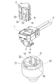
図1は、本発明の電気コネクタに用いられるコネクタ筐体1、ロック部材2、及びスクイブ20の係合前の各単体部材を図示している。ロック部材2をコネクタ筐体1に挿入すると、電線5の挿入方向前方面に位置したコネクタ筐体1に挿入される平行な2本のビーム25と、該前方面との2つの直交面に延びる前記ビーム25と平行な2本の第2アーム23とが前記コネクタ筐体1の一部である摺動面を摺動しながら挿入される。また、ロック部材2において、対向する前記第2アーム23の間隔より幅広で自由端にスクイブ20のラッチ収容部及び係合部に向いたラッチ部16を有する第1アーム4が弾性変形可能にコネクタの挿入方向に延びている。また、スクイブ20は円筒状に形成されており、開口部22の一部の端縁にはコネクタ筐体1を案内する案内部21と、円筒内のキャビティ14において突出し、コネクタ筐体1内に挿入される電気接触子10とを具備する。
FIG. 1 illustrates each single member before engagement of the
図2(a)は、内部で電気接続端子に接続された2本の電線5が挿入されたコネクタ筐体1においてロック部材2が仮係止された状態の前方斜視図である。前記コネクタ筐体1は、モールドで一体形成されており、スクイブ20と係合するラッチ面6を有する一対の第3アーム3が弾性変形可能にコネクタの挿入方向に延在している。ロック部材2には、スクイブ20と係合するラッチ部16においてラッチ面7を有する一対の第1アーム4がコネクタの挿入方向に延在している。しかし、現段階では、該第1アーム4の自由端は第3アーム3の自由端より挿入方向後方に位置している。図2(b)は同様にコネクタ筐体1とロック部材2の仮係止された状態の後方斜視図である。
FIG. 2A is a front perspective view of a state in which the
本発明の電気コネクタの接続手順を説明すると、まず、ロック部材2が仮係止された状態でコネクタ筐体1をスクイブ20に挿入する。当該挿入動作が完了すると、前記コネクタ筐体1の第3アーム3のラッチ部がスクイブ20の収容部に収容され、ラッチ面6とスクイブ20の係合部とが嵌合又は係合される。このとき、コネクタ筐体1に収容された電線と接続された電気接触子は、スクイブ20に具備された電気接触子10と既に電気接続されている。さらに、前記仮係止されていたロック部材2をコネクタ挿入方向に押圧して前記ラッチ面6とスクイブ20との嵌合を固定又はロックする。以上のようなロック部材2を挿入して当該固定を完了するまでの過程において、ロック部材2の第1アーム4のラッチ面7がスクイブ20の係合部で係合される過程を図3ないし図6を参照して以下に詳述する。
The electrical connector connection procedure of the present invention will be described. First, the
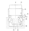
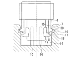
図3は、図2(a)のA−Bの断面を示した概要図である。コネクタ筐体1は既にスクイブ20に挿入されており、コネクタ接続を実現している。ロック部材2は挿入準備段階の状態であり、第1アーム4のラッチ部16は、第3アーム3のラッチ部の挿入方向後方に位置している。図4ないし図7も同様の断面図であって、当該ロック部材2をスクイブ20への挿入方向に挿入した際の各状態を示した様態図である。各断面図とも一点鎖線Xに対して対称である。以下に共通の構成要素を説明する。ラッチ面が点線で係止されたアームはコネクタ筐体1の第3アーム3であり、既にスクイブ20と係止されている。また、スクイブ20のキャビティ14内の底部から突出した2本のビーム(点線部を含む)はコネクタ筐体1に挿入された電気接触子10であり、既に電気接続されている。符号12は、当該コネクタ筐体1の一部断面を示しており、符号13はコネクタ筐体1に挿入されたロック部材2の一部である第1アーム4の枠幅を示している。
FIG. 3 is a schematic view showing a cross section taken along the line AB of FIG. The
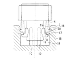
続いて、図4は、ロック部材2をコネクタ筐体1及びスクイブ20に挿入する過程において、第1アーム4が最も弾性変形した状態を図示している。ロック部材2を挿入方向に押圧していくと、各第1アーム4は、ラッチ面7を有するラッチ部16がスクイブ20の案内面15を摺動しながら互いに対向する方向に弾性的に偏倚し、スクイブ20のキャビティ14の方向に案内される。このとき、ロック部材2に具備された前記第2アーム23(図示されていない)は、前記第1アーム4が案内されると共に、前記コネクタ筐体1の摺動面と前記第3アーム3との間をコネクタ挿入方向に摺動する。
Next, FIG. 4 illustrates a state in which the
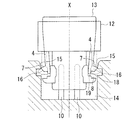
続いて、図5は、ロック部材2をコネクタ筐体1及びスクイブ20に挿入する過程において、第1アーム4が復元動作を開始した状態を図示している。前記第1アーム4の前記案内されたラッチ部16は、案内面15の終端部で前記案内が終了され、前記第1アーム4の弾性復元力によりスクイブ20内の収容部17の方向への移動を開始する。図6は、ロック部材2をコネクタ筐体1及びスクイブ20に挿入する過程において、第1アーム4が復元動作を完了した状態を図示している。前記第1アーム4の弾性復元力によって前記終端部がラッチ面7に沿って摺動し、第1アーム4の復元完了位置で当該動作が終了する。ラッチ部16は、スクイブ20の収容凹部17の所定位置に収容される。
Subsequently, FIG. 5 illustrates a state in which the
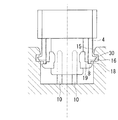
最後に、図7は、ロック部材2をコネクタ筐体1及びスクイブ20に挿入する過程において、前記ロック部材2が完全に挿入された状態を図示している。つまり、前記第1アーム4の自由端に形成された突出部18はコネクタ筐体1に画成された第1アーム載置部8に載置される。このとき、第2アーム23(図示されていない)は、前記摺動面と前記第3アーム3との間に介在して前記各第3アーム3の対向方向への弾性変形を規制している。これにより、第3アーム3とスクイブ20との係合は固定又はロックされる。
Finally, FIG. 7 illustrates a state in which the
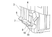
図8は、図7における第3アーム3及び第1アーム4の近傍を拡大した斜視図である。図5ないし図7における第1アーム4の一連の動作について、図8を参照しながら説明する。図8に示されたように、第1アーム4の挿入方向の面とラッチ面7がなす鈍角は、第3アーム3の挿入方向の面とラッチ面6とのなす鈍角よりも小さい。つまり、各アームのラッチ面がスクイブ20の収容部を画成する一面30となす傾斜角は、第1アーム4のラッチ面7の方が急勾配であり、第3アーム3のラッチ面6と比較して前記面30に達するまでにアームの挿入方向に対して距離差があるため、図6に図示されたように、第1アーム4が完全に弾性復元する際に、第1アーム4の自由端突出部18は前記段差19と接することはないので、図7においてロック部材2の完全挿入により所定の載置部8で保持することができる。図示されていないが、別の手段として、各アームに対して前記ラッチ面7及び前記ラッチ面6の傾斜を開始する基端の位置を挿入方向に対して前後させても挿入方向に対して距離差を発生させることができるため、図6及び図7について説明したような同様の効果を得ることができる。
FIG. 8 is an enlarged perspective view of the vicinity of the
ロック部材2が完全に挿入された状態のコネクタ筐体1の斜視図が図2(c)及び図2(d)に示されている。これにより、前記第1アーム4の自由端突出部18は、該第1アーム4の弾性変形方向において前記第1アーム載置部8との段差部19に当接しているため、各第1アーム4の対向方向への偏倚が規制される。
FIGS. 2C and 2D are perspective views of the
以上のように、ロック部材2が完全に挿入されると、各第1アーム4は、該第1アーム4の対向方向への弾性変形が規制されて固定される。よって、第2アームも固定されることとなり、第3アームとスクイブ20との係合が解除されることはない。
As described above, when the
ロック部材2が完全に挿入され、コネクタ接続が固定又はロックされた状態において、例えば、電線5の延在方向及びその垂直方向に引張力を受けると、コネクタ筐体1の第3アーム3とスクイブ20との係合部、及びロック部材2の挿入が完全でない場合におけるロック部材2の第1アーム4とスクイブ20との係合部が外力を受けて、各ラッチ面及びラッチ部が損傷されることが考えられる。したがって、当該外力に対する耐久性を提供するために、本発明のコネクタ筐体1及びロック部材2がガラス繊維を含有する素材で形成されることが好ましい。ガラス繊維が含有された素材は、強度及び可撓性にも優れている。しかし、当該素材は高価であるため、一例として、コネクタ筐体1のみを当該素材を用いて一体成形すれば経済的であり、第3アーム3が固定又はロックされた状態で引張力等の外力が加わっても、より高い耐久性が得られる。別の手段として、ロック部材2が当該素材で一体成形されてもよいし、第3アーム又は第1アームのみがガラス繊維を含有する素材で形成されてもよいことは当業者には自明である。
In a state where the
1・・・コネクタ筐体
2・・・ロック部材
3・・・第3アーム
4・・・第1アーム
5・・・電線
6・・・第3アームのラッチ面
7・・・第1アームのラッチ面
8・・・第1アーム自由端載置部
10・・電気接触子
11・・スクイブの係止部近傍
12・・コネクタ筐体の一部
13・・ロック部材の一部
14・・スクイブのキャビティ
15・・スクイブの第1アーム案内面
16・・ラッチ部
17・・凹部
18・・第1アーム自由端突出部
19・・段差部
20・・スクイブ
21・・案内部
22・・開口部
23・・第2アーム
25・・ビーム
30・・収容部を画成する一面
DESCRIPTION OF
Claims (4)
前記ロック部材は、前記スクイブと係合可能なラッチ面を有する一対の平行に延びる第1アームと、前記第1アームと平行な一対の第2アームとを有し、
前記コネクタ筐体は、前記スクイブと係合可能なラッチ面を有する、前記第1アームと平行に延びる一対の第3ラッチアームと、前記ロック部材が摺動可能な摺動面と、前記第1ラッチアームの自由端を載置可能な突出部とを有し、
前記ロック部材がロック解除位置からロック完了位置まで前記コネクタ筐体に沿って摺動したときに、前記各第1ラッチアームは互いに対向方向に弾性変形して前記スクイブとの係合を可能にし、ロック位置では前記第1ラッチアームの自由端が前記コネクタ筐体の突出部に載置されると同時に、前記第2アームは前記摺動可能な面と第3アームとの間に挿入される電気コネクタ。 An electrical connector that fits into a squib to achieve electrical connection, and includes a lock member and a connector housing,
The lock member includes a pair of parallel extending first arms having a latch surface engageable with the squib, and a pair of second arms parallel to the first arm,
The connector housing has a latch surface that can be engaged with the squib, a pair of third latch arms extending in parallel with the first arm, a sliding surface on which the lock member can slide, and the first A protrusion on which the free end of the latch arm can be placed;
When the locking member slides along the connector housing from the unlocking position to the locking completion position, the first latch arms are elastically deformed in opposite directions to enable engagement with the squib, In the locked position, the free end of the first latch arm is placed on the protruding portion of the connector housing, and at the same time, the second arm is inserted between the slidable surface and the third arm. connector.
Priority Applications (2)
| Application Number | Priority Date | Filing Date | Title |
|---|---|---|---|
| JP2003431701A JP2005190860A (en) | 2003-12-26 | 2003-12-26 | Electric connector |
| PCT/JP2004/019357 WO2005064753A1 (en) | 2003-12-26 | 2004-12-24 | Electrical connector |
Applications Claiming Priority (1)
| Application Number | Priority Date | Filing Date | Title |
|---|---|---|---|
| JP2003431701A JP2005190860A (en) | 2003-12-26 | 2003-12-26 | Electric connector |
Publications (1)
| Publication Number | Publication Date |
|---|---|
| JP2005190860A true JP2005190860A (en) | 2005-07-14 |
Family
ID=34736445
Family Applications (1)
| Application Number | Title | Priority Date | Filing Date |
|---|---|---|---|
| JP2003431701A Ceased JP2005190860A (en) | 2003-12-26 | 2003-12-26 | Electric connector |
Country Status (2)
| Country | Link |
|---|---|
| JP (1) | JP2005190860A (en) |
| WO (1) | WO2005064753A1 (en) |
Cited By (4)
| Publication number | Priority date | Publication date | Assignee | Title |
|---|---|---|---|---|
| JP2007305541A (en) * | 2006-05-15 | 2007-11-22 | Sumitomo Wiring Syst Ltd | Connector |
| WO2008126712A1 (en) * | 2007-04-10 | 2008-10-23 | Tyco Electronics Amp K.K. | Electrical connector assembly |
| JP2012048901A (en) * | 2010-08-25 | 2012-03-08 | Yazaki Corp | Connector |
| JP2014525111A (en) * | 2011-07-25 | 2014-09-25 | 矢崎総業株式会社 | connector |
Families Citing this family (1)
| Publication number | Priority date | Publication date | Assignee | Title |
|---|---|---|---|---|
| JP5058696B2 (en) * | 2007-07-19 | 2012-10-24 | 矢崎総業株式会社 | Locking connector |
Citations (5)
| Publication number | Priority date | Publication date | Assignee | Title |
|---|---|---|---|---|
| US5529512A (en) * | 1994-12-30 | 1996-06-25 | Methode Electronics, Inc. | Connector with low insertion force |
| GB2310087A (en) * | 1996-02-12 | 1997-08-13 | Whitaker Corp | Push button latching and locking mechanism |
| JP2000509194A (en) * | 1996-04-30 | 2000-07-18 | フラマトム コネクターズ インターナショナル | Connector with secondary latch and lateral cable outlet |
| JP2002124345A (en) * | 2000-10-16 | 2002-04-26 | Oki Electric Cable Co Ltd | Male and female connectors for preventing reverse insertion |
| JP2002198126A (en) * | 2000-11-17 | 2002-07-12 | Fci | Plug connector having auxiliary locking device |
-
2003
- 2003-12-26 JP JP2003431701A patent/JP2005190860A/en not_active Ceased
-
2004
- 2004-12-24 WO PCT/JP2004/019357 patent/WO2005064753A1/en active Application Filing
Patent Citations (5)
| Publication number | Priority date | Publication date | Assignee | Title |
|---|---|---|---|---|
| US5529512A (en) * | 1994-12-30 | 1996-06-25 | Methode Electronics, Inc. | Connector with low insertion force |
| GB2310087A (en) * | 1996-02-12 | 1997-08-13 | Whitaker Corp | Push button latching and locking mechanism |
| JP2000509194A (en) * | 1996-04-30 | 2000-07-18 | フラマトム コネクターズ インターナショナル | Connector with secondary latch and lateral cable outlet |
| JP2002124345A (en) * | 2000-10-16 | 2002-04-26 | Oki Electric Cable Co Ltd | Male and female connectors for preventing reverse insertion |
| JP2002198126A (en) * | 2000-11-17 | 2002-07-12 | Fci | Plug connector having auxiliary locking device |
Cited By (6)
| Publication number | Priority date | Publication date | Assignee | Title |
|---|---|---|---|---|
| JP2007305541A (en) * | 2006-05-15 | 2007-11-22 | Sumitomo Wiring Syst Ltd | Connector |
| WO2008126712A1 (en) * | 2007-04-10 | 2008-10-23 | Tyco Electronics Amp K.K. | Electrical connector assembly |
| JP2008262734A (en) * | 2007-04-10 | 2008-10-30 | Tyco Electronics Amp Kk | Electric connector assembly |
| JP2012048901A (en) * | 2010-08-25 | 2012-03-08 | Yazaki Corp | Connector |
| JP2014525111A (en) * | 2011-07-25 | 2014-09-25 | 矢崎総業株式会社 | connector |
| US9172187B2 (en) | 2011-07-25 | 2015-10-27 | Yazaki Corporation | Electrical connector |
Also Published As
| Publication number | Publication date |
|---|---|
| WO2005064753A1 (en) | 2005-07-14 |
Similar Documents
| Publication | Publication Date | Title |
|---|---|---|
| KR100454601B1 (en) | Structure for locking two workpieces | |
| JP4554376B2 (en) | connector | |
| JP4550470B2 (en) | connector | |
| US7654865B2 (en) | Electrical connector | |
| JP5789494B2 (en) | Connector and connector manufacturing method | |
| JPH0973950A (en) | Movable connector | |
| EP1158621A2 (en) | A connector housing | |
| KR940000093B1 (en) | Electric connector | |
| KR101234175B1 (en) | Self-aligning connector | |
| CN112652902B (en) | Electrical connector for flat conductor | |
| CN110739573B (en) | Electrical connector | |
| JP6196961B2 (en) | connector | |
| JP2005190860A (en) | Electric connector | |
| KR100446796B1 (en) | Connector | |
| KR100838786B1 (en) | Connector housing | |
| TWI707504B (en) | Terminals and connectors | |
| CN112839455B (en) | Electronic device with a detachable cover | |
| JP2000058155A (en) | Terminal board | |
| JP6886329B2 (en) | Electrical connector | |
| JP6887291B2 (en) | Electrical connector | |
| JP2006202536A (en) | Connector | |
| JP2014120261A (en) | Connector | |
| EP1872442B1 (en) | Electrical connector | |
| JP2022148390A (en) | connector | |
| KR100881101B1 (en) | Connector with terminal-inserting function |
Legal Events
| Date | Code | Title | Description |
|---|---|---|---|
| A131 | Notification of reasons for refusal |
Free format text: JAPANESE INTERMEDIATE CODE: A131 Effective date: 20061107 |
|
| A521 | Written amendment |
Free format text: JAPANESE INTERMEDIATE CODE: A523 Effective date: 20070207 |
|
| A01 | Written decision to grant a patent or to grant a registration (utility model) |
Free format text: JAPANESE INTERMEDIATE CODE: A01 Effective date: 20071106 |
|
| A045 | Written measure of dismissal of application |
Free format text: JAPANESE INTERMEDIATE CODE: A045 Effective date: 20080415 |