JP2005188564A - Polygon bolt - Google Patents
Polygon bolt Download PDFInfo
- Publication number
- JP2005188564A JP2005188564A JP2003427857A JP2003427857A JP2005188564A JP 2005188564 A JP2005188564 A JP 2005188564A JP 2003427857 A JP2003427857 A JP 2003427857A JP 2003427857 A JP2003427857 A JP 2003427857A JP 2005188564 A JP2005188564 A JP 2005188564A
- Authority
- JP
- Japan
- Prior art keywords
- bolt
- corner
- annular body
- head
- bolt head
- Prior art date
- Legal status (The legal status is an assumption and is not a legal conclusion. Google has not performed a legal analysis and makes no representation as to the accuracy of the status listed.)
- Pending
Links
Images
Landscapes
- Connection Of Plates (AREA)
Abstract
【課題】 軸部が十分に発生し得る軸力の範囲内で、締め付け荷重を向上できるように頭部構造を改良した多角ボルトを提供する。
【解決手段】 多角ボルトであって、軸部と頭部とから成るボルト本体と、該頭部に密着嵌合した環状体とから成り、該環状体は、外周が該ボルト頭部に対して相似形で大きく、かつ、上記ボルト本体より高強度の材料から成ることを特徴とする。更に、ボルト頭部の中心から各角部を通って放射状に延びる直線上に、環状体外周の各角部が位置していることを特徴とする。または、ボルト頭部の中心から各角部を通って放射状に延びる直線から外れた位置に、環状体外周の各角部が位置していることを特徴とする。
【選択図】 図2
PROBLEM TO BE SOLVED: To provide a polygonal bolt having an improved head structure so that a tightening load can be improved within a range of an axial force that can sufficiently generate a shaft portion.
SOLUTION: A polygonal bolt comprising a bolt main body comprising a shaft portion and a head, and an annular body closely fitted to the head, the outer circumference of the annular body with respect to the bolt head. It is similar in shape and is made of a material that is stronger than the bolt body. Furthermore, each corner | angular part of a cyclic | annular body outer periphery is located on the straight line extended radially through each corner | angular part from the center of a bolt head, It is characterized by the above-mentioned. Alternatively, each corner of the outer periphery of the annular body is located at a position deviated from a straight line extending radially from the center of the bolt head through each corner.
[Selection] Figure 2
Description
本発明は、締め付け荷重を向上させた多角ボルトに関する。 The present invention relates to a polygonal bolt with improved tightening load.
一般にボルトは、頭部と軸部が共に同一の材料で一体として成形される。そのため、軸部としては大きな軸力を発生できる場合であっても、頭部の弾性変形あるいは塑性変形によって、締め付け荷重が低く制限されることがある。このような頭部の塑性変形を利用して締め付けトルクを一定にするように頭部を二重構造にしたボルトが特許文献1、2に開示されている。
Generally, a bolt is integrally formed of the same material for the head and the shaft. Therefore, even if a large axial force can be generated as the shaft portion, the tightening load may be limited to be low due to elastic deformation or plastic deformation of the head.
しかし、これら従来技術では、頭部の塑性変形を抑制して締め付け荷重を向上させることはできなかった。また、締め付け時に頭部が塑性変形すると、再締め付けや取り外しができないという欠点もあった。 However, these conventional techniques cannot suppress the plastic deformation of the head and improve the tightening load. In addition, when the head is plastically deformed at the time of tightening, there is a disadvantage that it cannot be retightened or removed.
本発明は、軸部が十分に発生し得る軸力の範囲内で、締め付け荷重を向上できるように頭部構造を改良した多角ボルトを提供することを目的とする。 An object of this invention is to provide the polygonal bolt which improved the head structure so that a clamping load can be improved within the range of the axial force which a shaft part can fully generate | occur | produce.
上記の目的を達成するために、本発明の多角ボルトは、軸部と頭部とから成るボルト本体と該頭部に密着嵌合した環状体とから成り、該環状体は外周が該ボルト頭部に対して相似形で大きくかつ上記ボルト本体より高強度の材料から成ることを特徴とする。 In order to achieve the above object, the polygonal bolt of the present invention comprises a bolt body composed of a shaft portion and a head portion and an annular body closely fitted to the head portion, and the annular body has an outer periphery that is the bolt head portion. It is characterized in that it is made of a material that is similar in shape and larger to the part and stronger than the bolt body.
本発明の多角ボルトは、ボルト本体より高強度の環状体をボルト頭部に密着嵌合させたことにより、締め付け工具からの荷重によるボルト頭部の変形が低減し、締め付け荷重が向上する。 In the polygonal bolt according to the present invention, by deforming the bolt head due to the load from the tightening tool, the tightening load is improved by closely fitting the annular body having higher strength than the bolt main body to the bolt head.
環状体は、ボルト本体(頭部+軸部)より高強度であることにより、ボルト頭部が変形する締め付け荷重よりも高い締め付け荷重まで変形せずに原形を維持できる。 Since the annular body has higher strength than the bolt body (head portion + shaft portion), it can maintain the original shape without being deformed to a tightening load higher than the tightening load that deforms the bolt head portion.
この環状体はボルト頭部に密着嵌合していることが必須である。これは以下の理由による。
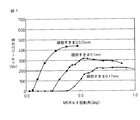
すなわち、一般にボルト頭部と工具ソケットとの間には規格範囲内の隙間が設定されているため、工具負荷(締め付け、開放)時には工具ソケット内面はボルト頭部角部に当接し、荷重は角部に集中的に負荷され、過剰負荷があると角部が変形する。図1は、アルミニウム製の六角ボルト(JIS M8ボルト)について、締め付け工具ソケットとボルト頭部との隙間を種々に変えたときの、ボルト回転角と締め付けトルクとの関係を示すグラフである。角部の変形が進行するのに伴い当接面積が増加して、より大きな荷重に耐えるようになるが、変形が進行してボルト頭部の実効径が工具ソケットの実効径まで小さくなると、両者は互いに滑ってしまい、締め付けトルクが低下する(またはゼロになる)。図中の各曲線はこの経緯に対応している。
It is essential that this annular body is closely fitted to the bolt head. This is due to the following reason.
In other words, since a gap within the standard range is generally set between the bolt head and the tool socket, the inner surface of the tool socket abuts against the corner of the bolt head when the tool is loaded (tightened or released), and the load is angular. If the load is concentrated on the part and there is an excessive load, the corner part is deformed. FIG. 1 is a graph showing the relationship between the bolt rotation angle and the tightening torque when the gap between the tightening tool socket and the bolt head is variously changed for an aluminum hexagon bolt (JIS M8 bolt). As the deformation of the corner progresses, the contact area increases and can withstand a larger load, but when the deformation progresses and the effective diameter of the bolt head decreases to the effective diameter of the tool socket, both Slip to each other and the tightening torque decreases (or becomes zero). Each curve in the figure corresponds to this process.
図から分かるように、ボルト頭部と工具ソケットとの隙間が大きくなるほど締め付けトルクは低下する。これは、隙間が大きくなると、工具ソケット内面とボルト頭部角部との当接角度が大きくなり、角部への荷重集中の度合いが大きくなるためである。 As can be seen from the figure, the tightening torque decreases as the gap between the bolt head and the tool socket increases. This is because as the gap increases, the contact angle between the inner surface of the tool socket and the bolt head corner increases, and the degree of load concentration on the corner increases.
本発明においては、上記知見に基づき、ボルト頭部と高強度環状体とを密着嵌合させることにより、上記の隙間を実質的にゼロにして、工具から環状体を介してボルト頭部へ負荷される荷重を角部に集中させずボルト頭部側面に分散させる。環状体はボルト本体よりも高強度なので従来のボルト頭部変形開始荷重よりも大きい荷重まで耐える。その結果、従来はボルト頭部の角部変形により到達できなかった高い荷重まで締め付けることが可能になった。 In the present invention, based on the above findings, the bolt head and the high-strength annular body are closely fitted to each other, so that the gap is substantially zero, and the load is applied from the tool to the bolt head via the annular body. Disperse the applied load on the side of the bolt head without concentrating on the corner. Since the annular body has higher strength than the bolt body, it can withstand a load larger than the conventional bolt head deformation starting load. As a result, it has become possible to tighten up to a high load that could not be reached by the deformation of the corners of the bolt head.
環状体は、外周形状がボルト頭部の輪郭と相似形なので、従来のボルト締め付け工具をそのまま用いることができる。 Since the annular body has an outer peripheral shape similar to the contour of the bolt head, a conventional bolt tightening tool can be used as it is.
本発明の多角ボルトは、ボルト頭部の中心から各角部を通って放射状に延びる直線上に、環状体外周の各角部が位置している構造であっても締め付け荷重向上効果が得られるが、ボルト頭部の中心から各角部を通って放射状に延びる直線から外れた位置に、環状体外周の各角部が位置する構造とすることにより締め付け荷重向上効果が更に大きくなる。 The polygonal bolt of the present invention can obtain a tightening load improving effect even if the corners of the outer periphery of the annular body are positioned on a straight line extending radially from the center of the bolt head through each corner. However, the effect of improving the tightening load is further increased by adopting a structure in which each corner of the outer periphery of the annular body is located at a position deviated from a straight line extending radially from the center of the bolt head through each corner.
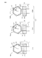
図2に本発明によるボルトの諸形態を示す。図2に示す各ボルト100、100A、100Bはいずれも、頭部12および軸部14から成るボルト本体10と、頭部12に密着嵌合した環状体20とから成る。環状体20は、外周がボルト頭部12に対して相似形で大きく、かつ、ボルト本体10よりも高強度の材料で作られている。
FIG. 2 shows various forms of bolts according to the present invention. Each of the
例えば、ボルト本体10がアルミニウム製である場合、環状体20としては高強度ボルト用の鋼材等を用いる。
For example, when the bolt
ボルト頭部12と環状体20との密着嵌合は、圧入、焼嵌め等により行なう。
The close fitting of the
図2(1)に示す多角ボルト100は、ボルト頭部12の中心Oから各角部K1を通って放射状に延びる直線L上に、環状体20の外周の各角部K2が位置している。ボルト頭部12への環状体20の密着嵌合による荷重分散効果が得られる。
In the
図2(2A)、(2B)にそれぞれ示す多角ボルト100A、100Bはいずれも、ボルト頭部12の中心Oから各角部K1を通って放射状に延びる直線Lから外れた位置に、環状体20の外周の各角部K2が位置している。
Each of the
具体的には、図2(2A)のボルト100Aは右ネジであり、締め付け時の回転方向(時計回り)に対して、環状体20の角部K2はボルト頭部12の角部K1より遅れ角θだけずれて位置している。また、図2(2B)のボルト100Bは左ネジであり、締め付け時の回転方向(反時計回り)に対して、環状体20の角部K2はボルト頭部12の角部K1より遅れ角θだけずれて位置している。
Specifically, the
このようにボルト頭部12の角部K1に対してずらして環状体20の角部K2を配置することにより、ボルト頭部12と環状体20との接触面で発生する摩擦力を積極的に利用して更に大きなトルクを伝達できる。したがって、位置ずれ効果を得るためには、遅れ角θを、ボルト頭部12と環状体20との摩擦係数μに対応する摩擦角θf以上にすることが望ましい。すなわち、遅れ角θ≧θf=tan-1(μ)とすることが望ましい。
Thus, by disposing the corner portion K2 of the
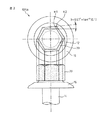
例えば、図3に示した本発明の多角ボルト101Aは、頭部12と軸部14と両者間の座金鍔16とが一体に成形された右ネジ(締め付け方向が時計回り)であり、環状体20の角部K2はボルト頭部12の角部K1に対して遅れ角θ≧θfとなるように作製されている。この例では、ボルト頭部12と環状体20との接触面の摩擦係数μ=0.1であり、θ≧θf=tan-1(0.1)=5.7°に設定されている。
For example, the
一般に、締め付けトルクと緩めトルクとには差があり、締め付けトルクの方が通常は約2割大きい。上記のθ=5.7°の値は、締め付けトルクに対応できるように設定したものである。締め付け時に高面圧になる位置は環状体20が厚く、緩め時に高面圧になる位置は環状体20が薄くなるようにして強度のバランスをとれば、重い高強度材料の使用量を極力少なくすることができる。
Generally, there is a difference between the tightening torque and the loosening torque, and the tightening torque is usually about 20% larger. The value of θ = 5.7 ° is set so as to correspond to the tightening torque. If the strength of the
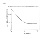
図4に、ボルト頭部12の角部K1に対する環状体20の角部K2の遅れ角θと、荷重負荷時のボルト角部K1の変形量との関係を示す。θが大きくなるほどボルト角部K1の変形量は小さくなり、破壊し難くなる。
FIG. 4 shows the relationship between the delay angle θ of the corner portion K2 of the
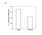
図5に、環状体20を用いない比較例と、環状体20を用いた本発明例とについて、ボルト角部K1の変形量を比較して示す。図示したように、本発明の環状体20を具備したすることによりボルト角部K1の変形量が大幅に低減する。両者の変形量の比率は、ボルト本体10の材料のヤング率と環状体20の材料のヤング率の比率にほぼ反比例する。図示の例では、ボルト本体10がアルミニウム製、環状体20が鋼製であり、両者の変形量がヤング率にほぼ反比例していることが分かる。
FIG. 5 shows a comparison of the deformation amount of the bolt corner portion K1 for a comparative example that does not use the
本発明によれば、軸部が十分に発生し得る軸力の範囲内で、締め付け荷重を向上できるように頭部構造を改良した多角ボルトが提供される。 ADVANTAGE OF THE INVENTION According to this invention, the polygonal bolt which improved the head structure so that a clamp | tightening load can be improved within the range of the axial force which a shaft part can fully generate | occur | produce is provided.
100、100A、100B、101A…本発明の環状体付き多角ボルト
10…ボルト本体
12…ボルト頭部
14…ボルト軸部
20…環状体
O…ボルト頭部の中心
K1…ボルト頭部の角部
K2…環状体の角部
L…ボルト頭部12の中心Oから各角部K1を通って放射状に延びる直線
θ…遅れ角
100, 100A, 100B, 101A ...
Claims (3)
該環状体は、外周が該ボルト頭部に対して相似形で大きく、かつ、上記ボルト本体より高強度の材料から成ることを特徴とする多角ボルト。 A bolt body composed of a shaft portion and a head portion, and an annular body closely fitted to the head portion,
The polygonal bolt characterized in that the annular body is made of a material whose outer periphery is similar and large to the bolt head and is stronger than the bolt body.
2. The polygonal bolt according to claim 1, wherein each corner of the outer periphery of the annular body is located at a position deviated from a straight line extending radially from the center of the bolt head through each corner.
Priority Applications (1)
| Application Number | Priority Date | Filing Date | Title |
|---|---|---|---|
| JP2003427857A JP2005188564A (en) | 2003-12-24 | 2003-12-24 | Polygon bolt |
Applications Claiming Priority (1)
| Application Number | Priority Date | Filing Date | Title |
|---|---|---|---|
| JP2003427857A JP2005188564A (en) | 2003-12-24 | 2003-12-24 | Polygon bolt |
Publications (1)
| Publication Number | Publication Date |
|---|---|
| JP2005188564A true JP2005188564A (en) | 2005-07-14 |
Family
ID=34787014
Family Applications (1)
| Application Number | Title | Priority Date | Filing Date |
|---|---|---|---|
| JP2003427857A Pending JP2005188564A (en) | 2003-12-24 | 2003-12-24 | Polygon bolt |
Country Status (1)
| Country | Link |
|---|---|
| JP (1) | JP2005188564A (en) |
-
2003
- 2003-12-24 JP JP2003427857A patent/JP2005188564A/en active Pending
Similar Documents
| Publication | Publication Date | Title |
|---|---|---|
| US5772377A (en) | Capped wheel fastener | |
| TW523574B (en) | Anti-loosening nut assembly | |
| US4898429A (en) | Wheel nut assembly | |
| CA2537081A1 (en) | Lock nut | |
| GB1564684A (en) | Socket head fasteners | |
| US20210010504A1 (en) | Three-point fastener | |
| US6840139B2 (en) | Tapered installation tool | |
| JP2005188564A (en) | Polygon bolt | |
| JP6083632B1 (en) | Locking nut | |
| US5056870A (en) | Wheel nut assembly | |
| TWI239880B (en) | Socket for tightening, loosening or holding a hexagonal part underneath an equally sized hexagonal nut | |
| JP5677012B2 (en) | Fastening member | |
| EP1318316A3 (en) | Washer, fastener provided with a washer, and method of and power tool for fastening with the use of the washer | |
| EP0595952A1 (en) | Toothed fastener | |
| JPH01105012A (en) | Detent nut | |
| JPH039874Y2 (en) | ||
| JP2003021127A (en) | Fastener | |
| JP2006189065A (en) | Mounting structure | |
| JPS631047Y2 (en) | ||
| JP2000291852A (en) | Flexible pipe connection fitting | |
| EP4549758A1 (en) | Nut sleeve with locking and alignment features | |
| JPS6234027Y2 (en) | ||
| JP3013040U (en) | Loosening prevention nut | |
| JP2003294020A (en) | Shaft-mounted member | |
| JP2008230374A (en) | Wheel mounting structure and spacer |