JP2005185085A - Device and method for driving ultrasonic actuator - Google Patents
Device and method for driving ultrasonic actuator Download PDFInfo
- Publication number
- JP2005185085A JP2005185085A JP2004224501A JP2004224501A JP2005185085A JP 2005185085 A JP2005185085 A JP 2005185085A JP 2004224501 A JP2004224501 A JP 2004224501A JP 2004224501 A JP2004224501 A JP 2004224501A JP 2005185085 A JP2005185085 A JP 2005185085A
- Authority
- JP
- Japan
- Prior art keywords
- frequency
- ultrasonic actuator
- ultrasonic
- circuit
- phase difference
- Prior art date
- Legal status (The legal status is an assumption and is not a legal conclusion. Google has not performed a legal analysis and makes no representation as to the accuracy of the status listed.)
- Withdrawn
Links
- 238000000034 method Methods 0.000 title claims abstract description 104
- 238000001514 detection method Methods 0.000 claims abstract description 158
- 230000008859 change Effects 0.000 claims abstract description 16
- 238000010408 sweeping Methods 0.000 claims description 5
- 238000010030 laminating Methods 0.000 claims description 3
- 230000008569 process Effects 0.000 description 32
- 238000012545 processing Methods 0.000 description 18
- 230000004048 modification Effects 0.000 description 12
- 238000012986 modification Methods 0.000 description 12
- 238000010586 diagram Methods 0.000 description 11
- 230000010355 oscillation Effects 0.000 description 11
- 238000005452 bending Methods 0.000 description 9
- 230000003321 amplification Effects 0.000 description 8
- 238000006073 displacement reaction Methods 0.000 description 8
- 238000003199 nucleic acid amplification method Methods 0.000 description 8
- 230000007423 decrease Effects 0.000 description 3
- 230000004069 differentiation Effects 0.000 description 2
- 230000000694 effects Effects 0.000 description 2
- 238000003672 processing method Methods 0.000 description 2
- 230000008901 benefit Effects 0.000 description 1
- 239000000470 constituent Substances 0.000 description 1
- 238000003780 insertion Methods 0.000 description 1
- 230000037431 insertion Effects 0.000 description 1
- 229910000679 solder Inorganic materials 0.000 description 1
- 230000006641 stabilisation Effects 0.000 description 1
- 238000011105 stabilization Methods 0.000 description 1
- 238000012360 testing method Methods 0.000 description 1
Images


Classifications
-
- H—ELECTRICITY
- H02—GENERATION; CONVERSION OR DISTRIBUTION OF ELECTRIC POWER
- H02N—ELECTRIC MACHINES NOT OTHERWISE PROVIDED FOR
- H02N2/00—Electric machines in general using piezoelectric effect, electrostriction or magnetostriction
- H02N2/0005—Electric machines in general using piezoelectric effect, electrostriction or magnetostriction producing non-specific motion; Details common to machines covered by H02N2/02 - H02N2/16
- H02N2/0075—Electrical details, e.g. drive or control circuits or methods
- H02N2/008—Means for controlling vibration frequency or phase, e.g. for resonance tracking
-
- H—ELECTRICITY
- H02—GENERATION; CONVERSION OR DISTRIBUTION OF ELECTRIC POWER
- H02N—ELECTRIC MACHINES NOT OTHERWISE PROVIDED FOR
- H02N2/00—Electric machines in general using piezoelectric effect, electrostriction or magnetostriction
- H02N2/02—Electric machines in general using piezoelectric effect, electrostriction or magnetostriction producing linear motion, e.g. actuators; Linear positioners ; Linear motors
- H02N2/026—Electric machines in general using piezoelectric effect, electrostriction or magnetostriction producing linear motion, e.g. actuators; Linear positioners ; Linear motors by pressing one or more vibrators against the driven body
-
- H—ELECTRICITY
- H10—SEMICONDUCTOR DEVICES; ELECTRIC SOLID-STATE DEVICES NOT OTHERWISE PROVIDED FOR
- H10N—ELECTRIC SOLID-STATE DEVICES NOT OTHERWISE PROVIDED FOR
- H10N30/00—Piezoelectric or electrostrictive devices
- H10N30/20—Piezoelectric or electrostrictive devices with electrical input and mechanical output, e.g. functioning as actuators or vibrators
- H10N30/202—Piezoelectric or electrostrictive devices with electrical input and mechanical output, e.g. functioning as actuators or vibrators using longitudinal or thickness displacement combined with bending, shear or torsion displacement
- H10N30/2023—Piezoelectric or electrostrictive devices with electrical input and mechanical output, e.g. functioning as actuators or vibrators using longitudinal or thickness displacement combined with bending, shear or torsion displacement having polygonal or rectangular shape
Landscapes
- General Electrical Machinery Utilizing Piezoelectricity, Electrostriction Or Magnetostriction (AREA)
Abstract
Description
本発明は、超音波アクチュエータ駆動装置及び超音波アクチュエータ駆動方法に関し、特に超音波アクチュエータの例えば積層型の超音波振動子に周波電圧の駆動信号を印加することにより、駆動力を発生する超音波アクチュエータ駆動装置及び超音波アクチュエータ駆動方法に関する。 The present invention relates to an ultrasonic actuator driving apparatus and an ultrasonic actuator driving method, and more particularly to an ultrasonic actuator that generates a driving force by applying a frequency voltage driving signal to, for example, a laminated ultrasonic transducer of the ultrasonic actuator. The present invention relates to a driving apparatus and an ultrasonic actuator driving method.
近年、電磁型モータに代わる新しいモータとして超音波アクチュエータが注目されている。
この種の超音波アクチュエータは、通常、アクチュエータ駆動装置によって駆動制御が行われている。このアクチュエータ駆動装置は、前記超音波アクチュエータの超音波振動子に周波電圧の駆動信号を印加して、この超音波振動子に超音波楕円振動を発生させることにより、この超音波振動子、あるいはこの超音波振動子に接触している被駆動体を介して駆動力が得られるように制御している。
In recent years, ultrasonic actuators have attracted attention as new motors that replace electromagnetic motors.
This type of ultrasonic actuator is usually driven and controlled by an actuator driving device. The actuator driving device applies a frequency voltage drive signal to the ultrasonic vibrator of the ultrasonic actuator, and generates ultrasonic elliptical vibration in the ultrasonic vibrator. Control is performed so that a driving force is obtained via a driven body that is in contact with the ultrasonic transducer.
このような超音波アクチュエータ駆動装置による駆動方法の従来技術としては、例えば特開昭63−56178号公報に開示された超音波モータ駆動方法がある。この従来の超音波モータ駆動方法を実施するための超音波アクチュエータ駆動回路の構成例が図21に示されている。 As a prior art of a driving method using such an ultrasonic actuator driving apparatus, there is an ultrasonic motor driving method disclosed in, for example, Japanese Patent Laid-Open No. 63-56178. FIG. 21 shows a configuration example of an ultrasonic actuator driving circuit for implementing this conventional ultrasonic motor driving method.
図21示すように、従来の超音波アクチュエータ駆動装置は、超音波アクチュエータ駆動回路100と、この超音波アクチュエータ駆動回路100によって駆動が制御される超音波アクチュエータ101とを有している。
As shown in FIG. 21, the conventional ultrasonic actuator driving device has an ultrasonic actuator driving circuit 100 and an
前記超音波アクチュエータ駆動回路100は、発振回路102、電力増幅回路103、電流検出回路104、位相差検出回路105、位相差条件判定回路106、周波数制御回路107とを有し、前記超音波アクチュエータ101は電流検出回路104を介して電力増幅回路103に接続されている。
The ultrasonic actuator driving circuit 100 includes an
前記発振回路1は、後述する周波数制御回路107より出力される周波数制御信号107aにより決定される周波数の交番信号102aを生成し、電力増幅回路103に供給する。
前記電力増幅回路103は、交番信号102aを増幅し、得た駆動電圧信号103aを電流検出回路104及び位相差検出回路105に供給する。
前記電流検出回路104は、駆動電圧信号103aを超音波アクチュエータ101に印加したときに流れる電流を検出し、検出結果である駆動電流検出信号104aを位相差検出回路105に供給する。
前記位相差検出回路105は、駆動電圧信号103aと駆動電流検出信号104aとの位相差を検出し、検出結果である位相差検出信号105aを位相差条件判定回路106に供給する。
前記位相差条件判定回路106は、供給された位相差検出信号105aが所定の値になったときに位相差条件信号106aを周波数制御回路107に供給する。
前記周波数制御回路107は、この超音波アクチュエータ駆動回路100全体を制御する制御手段であり、交番信号102aが高い周波数から低い周波数へ掃引されるように周波数制御信号107aを発振回路102に供給してこの発振回路102による発振動作を制御する。
The
The
The
The phase
The phase difference
The
上記構成の超音波アクチュエータ駆動回路100において、前記周波数制御回路107は、位相差条件判定回路106より出力される位相差条件信号106aが出力されるまでは交番信号102aの周波数を掃引するように周波数制御信号107aを変化させ、位相差検出信号105aが所定の値となったときに掃引を停止するように制御する。すなわち、この周波数制御回路107は、駆動電流と駆動電圧の位相差が所定の値となる周波数の駆動電圧信号103を得るように制御することができるので、超音波アクチュエータ駆動回路100は、超音波アクチュエータ100の共振周波数と一定関係にある周波数での駆動を行うことが可能となる。
一般的な超音波アクチュエータでは、共振周波数より離れた周波数における駆動電流は、共振周波数付近における駆動電流に比較して小さい。したがって、上述した従来の超音波アクチュエータ駆動回路では、 周波数制御回路107による周波数掃引範囲内に前記駆動電流が小さい周波数範囲が含まれる場合、駆動電流検出信号がノイズに埋もれるため、周波数掃引中に実際の位相差とは異なる位相差が検出されることもある。その結果、アクチュエータの共振周波数に関係のない周波数で周波数掃引が終了してしまい、アクチュエータの共振周波数とは無関係の周波数で駆動することになり、駆動効率が悪くなってしまうといった問題点があった。
In a general ultrasonic actuator, the drive current at a frequency away from the resonance frequency is smaller than the drive current near the resonance frequency. Therefore, in the conventional ultrasonic actuator driving circuit described above, when the frequency sweeping range by the
そこで、本発明は上記問題点に鑑みてなされたもので、位相検出を正確に行うように構成したことにより、確実に共振周波数近傍での駆動を行うことができ、駆動効率の良い超音波アクチュエータ駆動装置及び超音波アクチュエータ駆動方法を提供することを目的とする。 Therefore, the present invention has been made in view of the above-described problems, and is configured to accurately detect the phase, so that it is possible to surely drive near the resonance frequency, and an ultrasonic actuator with high driving efficiency. It is an object to provide a driving device and an ultrasonic actuator driving method.
請求項1の発明の超音波アクチュエータ駆動方法は、圧電板と内部電極とを交互に積層してなる超音波振動子に交番信号を印加することにより駆動を行う超音波アクチュエータ駆動方法であって、前記交番信号の電圧と電流の振幅比が所定の値以上である周波数範囲内における、前記交番信号の電圧と電流の位相差が所定の状態となる周波数を検出し、駆動周波数をこの検出した周波数に設定することを特徴とするものである。
The ultrasonic actuator driving method of the invention of
請求項2の発明の超音波アクチュエータ駆動方法は、請求項1に記載の超音波アクチュエータ駆動方法において、前記交番信号の電圧と電流の振幅比が所定の値以上を取る最小の周波数を下限周波数として検出し、前記交番信号の電圧と電流の振幅比が所定の値以上を取る最大の周波数を上限周波数として検出する第1のステップと、前記第1のステップで検出された上限周波数と下限周波数で定義される周波数領域内で、前記交番信号の電圧と電流の位相差が所定の状態となる周波数を検出する第2のステップと、駆動周波数を前記第2のステップにより検出した周波数に設定する第3のステップと、を有したことを特徴とするものである。 An ultrasonic actuator driving method according to a second aspect of the present invention is the ultrasonic actuator driving method according to the first aspect, wherein a minimum frequency at which an amplitude ratio between the voltage and current of the alternating signal takes a predetermined value or more is set as a lower limit frequency. A first step of detecting, as an upper limit frequency, a maximum frequency at which the amplitude ratio of the voltage and current of the alternating signal takes a predetermined value or more, and an upper limit frequency and a lower limit frequency detected in the first step A second step of detecting a frequency at which the phase difference between the voltage and current of the alternating signal is in a predetermined state within a defined frequency region, and a drive frequency is set to the frequency detected by the second step. And 3 steps.
請求項3の発明の超音波アクチュエータ駆動方法は、請求項2に記載の超音波アクチュエータ駆動方法において、前記交番信号の周波数を下方から上方へ掃引しながら前記下限周波数の検出を行い、前記交番信号の周波数を上方から下方へ掃引しながら前記上限周波数の検出を行うことを特徴とするものである。 An ultrasonic actuator driving method according to a third aspect of the present invention is the ultrasonic actuator driving method according to the second aspect, wherein the lower limit frequency is detected while sweeping the frequency of the alternating signal from below to above, and the alternating signal The upper limit frequency is detected while sweeping the above frequency from the upper side to the lower side.
請求項4の発明の超音波アクチュエータ駆動方法は、請求項2に記載の超音波アクチュエータ駆動方法において、前記交番信号の周波数を離散的に変化させながら前記下限周波数の検出を行い、前記交番信号の周波数を離散的に変化させながら前記上限周波数の検出を行うことを特徴とするものである。 The ultrasonic actuator driving method according to a fourth aspect of the present invention is the ultrasonic actuator driving method according to the second aspect, wherein the lower limit frequency is detected while discretely changing the frequency of the alternating signal, The upper limit frequency is detected while discretely changing the frequency.
請求項5の発明の超音波アクチュエータ駆動方法は、請求項1に記載の超音波アクチュエータ駆動方法において、前記交番信号の電圧と電流の振幅比が所定の値以上であるか否かの判断と、前記交番信号の電圧と電流の位相差が所定の状態であるか否かの判断とを同時に行い、前記振幅比が所定の値以上で、かつ前記位相差が所定の状態となる周波数を検出し、駆動周波数をこの検出した周波数に設定することを特徴とするものである。 An ultrasonic actuator driving method according to a fifth aspect of the present invention is the ultrasonic actuator driving method according to the first aspect, wherein a determination is made as to whether or not the amplitude ratio of the voltage and current of the alternating signal is greater than or equal to a predetermined value. Simultaneously determining whether or not the phase difference between the voltage and current of the alternating signal is in a predetermined state, and detecting a frequency at which the amplitude ratio is equal to or greater than a predetermined value and the phase difference is in a predetermined state. The drive frequency is set to the detected frequency.
請求項6の発明の超音波アクチュエータ駆動方法は、請求項1乃至請求項5のいずれか1つに記載の超音波アクチュエータ駆動方法において、前記所定の状態は、周波数に対する前記位相差の変化量が最大となる状態であることを特徴とするものである。 An ultrasonic actuator driving method according to a sixth aspect of the present invention is the ultrasonic actuator driving method according to any one of the first to fifth aspects, wherein the predetermined state includes a change amount of the phase difference with respect to a frequency. It is characterized by being in a maximum state.
請求項7の発明の超音波アクチュエータ駆動方法は、請求項1乃至請求項5のいずれか1つに記載の超音波アクチュエータ駆動方法において、前記所定の状態は、周波数に対する前記位相差の変化量が所定の値を超えた状態であることを特徴とするものである。 An ultrasonic actuator driving method according to a seventh aspect of the present invention is the ultrasonic actuator driving method according to any one of the first to fifth aspects, wherein the predetermined state is a change amount of the phase difference with respect to a frequency. It is characterized by being in a state exceeding a predetermined value.
請求項8の発明の超音波アクチュエータ駆動方法は、請求項1乃至請求項7のいずれか1つに記載の超音波アクチュエータ駆動方法において、前記超音波振動子は、圧電板を同一方向に積層して構成される圧電積層体と、前記圧電積層体の側面に設けられ、所定の押圧力をもって被駆動部と接触する摩擦部材と、前記圧電積層体内部に設けられ、第1の電極群及び第2の電極群を有する内部電極と、前記内部電極に導通した第1の外部電極群及び第2の外部電極群を有し、前記第1の外部電極群及び/もしくは前記第2の外部電極群に駆動部により交番信号を印加して第1の振動モード及び第2の振動モードを同時に発生することにより、前記超音波振動子に超音波楕円振動を発生することを特徴とするものである。 An ultrasonic actuator driving method according to an eighth aspect of the present invention is the ultrasonic actuator driving method according to any one of the first to seventh aspects, wherein the ultrasonic vibrator is formed by stacking piezoelectric plates in the same direction. A piezoelectric laminated body configured on the side surface of the piezoelectric laminated body, a friction member that contacts a driven part with a predetermined pressing force, a first electrode group and a first electrode group An internal electrode having two electrode groups, a first external electrode group and a second external electrode group conducted to the internal electrode, and the first external electrode group and / or the second external electrode group An ultrasonic elliptical vibration is generated in the ultrasonic transducer by simultaneously generating a first vibration mode and a second vibration mode by applying an alternating signal to the drive unit.
請求項9の発明の超音波アクチュエータ駆動方法は、請求項1乃至請求項7のいずれか1つに記載の超音波アクチュエータ駆動方法において、前記超音波振動子は、前記摩擦部材を介して所定の押圧力を前記圧電積層体に与える第1及び第2のガイド部材に狭持されていることを特徴とするものである。 An ultrasonic actuator driving method according to a ninth aspect of the present invention is the ultrasonic actuator driving method according to any one of the first to seventh aspects, wherein the ultrasonic transducer is a predetermined member via the friction member. It is characterized in that it is sandwiched between first and second guide members for applying a pressing force to the piezoelectric laminate.
請求項10の発明の超音波アクチュエータ駆動方法は、請求項8又は請求項9に記載の超音波アクチュエータ駆動方法において、前記圧電積層体を所定の外形寸法とすることにより、前記所定の押圧力の下で、第1の振動モード及び第2の振動モードの共振周波数が一致するように構成されていることを特徴とするものである。 An ultrasonic actuator driving method according to a tenth aspect of the invention is the ultrasonic actuator driving method according to the eighth or ninth aspect, wherein the piezoelectric layered body has a predetermined outer dimension so that the predetermined pressing force is reduced. Below, it is comprised so that the resonant frequency of a 1st vibration mode and a 2nd vibration mode may correspond.
請求項11の発明の超音波アクチュエータ駆動装置は、圧電板と内部電極とを交互に積層した超音波振動子に交番信号を印加することにより駆動を行う超音波アクチュエータ駆動装置であって、前記交番信号を生成する駆動回路と、前記交番信号の電圧と電流の振幅比を検出する振幅検出回路と、前記交番信号の電圧と電流の位相差を検出する位相差検出回路と、前記振幅比と前記位相差から前記交番信号の周波数を設定する制御回路とを有し、前記制御回路は、前記振幅比が所定の値以上である周波数範囲内において、前記位相差が所定の状態となる周波数を検出し、駆動周波数を前記周波数に設定することを特徴とするものである。 An ultrasonic actuator driving apparatus according to an eleventh aspect of the present invention is an ultrasonic actuator driving apparatus that performs driving by applying an alternating signal to an ultrasonic vibrator in which piezoelectric plates and internal electrodes are alternately stacked. A drive circuit that generates a signal; an amplitude detection circuit that detects an amplitude ratio between the voltage and current of the alternating signal; a phase difference detection circuit that detects a phase difference between the voltage and current of the alternating signal; and the amplitude ratio and the A control circuit that sets the frequency of the alternating signal from a phase difference, and the control circuit detects a frequency at which the phase difference is in a predetermined state within a frequency range in which the amplitude ratio is equal to or greater than a predetermined value. The drive frequency is set to the frequency.
請求項12の発明の超音波アクチュエータ駆動装置は、請求項11に記載の超音波アクチュエータ駆動装置において、前記超音波振動子は、圧電板を同一方向に積層して構成される圧電積層体と、前記圧電積層体の側面に設けられ、所定の押圧力をもって被駆動部と接触する摩擦部材と、前記圧電積層体内部に設けられ、第1の電極群及び第2の電極群を有する内部電極と、前記内部電極に導通した第1の外部電極群及び第2の外部電極群を有し、前記第1の外部電極群及び/もしくは前記第2の外部電極群に駆動部により交番信号を印加して第1の振動モード及び第2の振動モードを同時に発生することにより、前記超音波振動子に超音波楕円振動を発生することを特徴とするものである。 An ultrasonic actuator driving device according to a twelfth aspect of the present invention is the ultrasonic actuator driving device according to the eleventh aspect, wherein the ultrasonic transducer includes a piezoelectric laminate configured by stacking piezoelectric plates in the same direction; A friction member provided on a side surface of the piezoelectric laminate and contacting a driven portion with a predetermined pressing force; an internal electrode provided in the piezoelectric laminate and having a first electrode group and a second electrode group; , Having a first external electrode group and a second external electrode group conducted to the internal electrode, and applying an alternating signal to the first external electrode group and / or the second external electrode group by a driving unit. By generating the first vibration mode and the second vibration mode at the same time, an ultrasonic elliptical vibration is generated in the ultrasonic vibrator.
請求項13の発明の超音波アクチュエータ駆動装置は、請求項11又は請求項12に記載の超音波アクチュエータ駆動装置において、前記超音波振動子は、前記摩擦部材を介して所定の押圧力を前記圧電積層体に与える第1及び第2のガイド部材に狭持されていることを特徴とするものである。 An ultrasonic actuator driving apparatus according to a thirteenth aspect of the present invention is the ultrasonic actuator driving apparatus according to the eleventh or twelfth aspect, wherein the ultrasonic transducer applies a predetermined pressing force via the friction member to the piezoelectric element. It is characterized by being sandwiched between first and second guide members applied to the laminate.
請求項14の発明の超音波アクチュエータ駆動装置は、請求項12又は請求項13に記載の超音波アクチュエータ駆動装置において、前記圧電積層体を所定の外形寸法とすることにより、前記所定の押圧力の下で、第1の振動モード及び第2の振動モードの共振周波数が一致するように構成されていることを特徴とするものである。 An ultrasonic actuator driving device according to a fourteenth aspect of the present invention is the ultrasonic actuator driving device according to the twelfth or the thirteenth aspect, wherein the piezoelectric laminated body has a predetermined outer dimension so that the predetermined pressing force is reduced. Below, it is comprised so that the resonant frequency of a 1st vibration mode and a 2nd vibration mode may correspond.
本発明の超音波アクチュエータ駆動装置及び超音波アクチュエータ駆動方法は、温度変化などの外部要因の変化に伴って超音波アクチュエータの共振状態が変化した場合でも、この超音波アクチュエータの共振周波数近傍を検出し、この検出した共振周波数近傍での駆動信号を用いることにより、駆動効率の良い状態にて超音波アクチュエータを駆動することができるといった利点がある。 The ultrasonic actuator driving apparatus and ultrasonic actuator driving method according to the present invention detects the vicinity of the resonance frequency of the ultrasonic actuator even when the resonance state of the ultrasonic actuator changes with changes in external factors such as temperature changes. By using a drive signal in the vicinity of the detected resonance frequency, there is an advantage that the ultrasonic actuator can be driven with good drive efficiency.
以下、図面を参照して本発明の実施例を説明する。 Embodiments of the present invention will be described below with reference to the drawings.
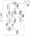
図1乃至図11は本発明の超音波アクチュエータ駆動方法の第1実施例を示し、図1は超音波アクチュエータ駆動方法を実現する超音波アクチュエータ駆動装置の全体構成を示すブロック図、図2(a)及び図2(b)は本実施例に係る超音波アクチュエータ駆動装置に用いられる超音波アクチュエータの構成例を示すもので、図2(a)は正面図、図2(b)は側面図、図3は超音波アクチュエータの第1変形例を示す正面図、図4乃至図6は超音波アクチュエータの圧電積層体の構成例を示し、図4はY軸方向に積層してなる圧電積層体の分解斜視図、図5はZ軸方向に積層してなる圧電積層体の分解斜視図、図6はX軸方向に積層してなる圧電積層体の分解斜視図、図7は超音波アクチュエータの第2変形例を示す正面図、図8は本実施例の超音波アクチュエータ駆動方法により駆動される超音波アクチュエータの特性を示す特性図であり、図8(a)は速度と周波数との特性を示すグラフ、図8(b)は電圧−電流位相差と周波数との特性を示すグラフ、図8(c)は駆動電流振幅と周波数との特性を示すグラフ、図8(d)は位相差検出信号と周波数との特性を示すグラフである。また、図9及び図11は本実施例の超音波アクチュエータ駆動方法を説明するためのもので、図9は周波数制御回路による駆動周波数を決定する周波数範囲の検出方法を説明するグラフであり、図9(a)は周波数範囲の下限周波数の検出方法を説明する駆動電流振幅と周波数との特性を示すグラフ、図9(b)は周波数範囲の上限周波数の検出方法を説明する駆動電流振幅と周波数との特性を示すグラフ、図9(c)は下限周波数及び上限周波数に基づく周波数範囲を説明する位相差検出信号と周波数との特性を示すグラフである。さらに、図10は図1の周波数領域検出回路からの検出結果に基づき共振周波数近傍を検出する検出方法を説明するグラフであり、図10(a)は検出初期時の電圧−電流位相差と周波数との特性を示すグラフ、図10(b)は検出過程時の電圧−電流位相差と周波数との特性を示すグラフである。図11は図1の周波数制御回路による共振周波数検出処理ルーチンの制御例を示すフローチャートである。 1 to 11 show a first embodiment of an ultrasonic actuator driving method according to the present invention, and FIG. 1 is a block diagram showing the overall configuration of an ultrasonic actuator driving device that realizes the ultrasonic actuator driving method. FIG. ) And FIG. 2B show a configuration example of the ultrasonic actuator used in the ultrasonic actuator driving apparatus according to the present embodiment, FIG. 2A is a front view, FIG. 2B is a side view, FIG. 3 is a front view showing a first modified example of the ultrasonic actuator, FIGS. 4 to 6 show structural examples of the piezoelectric laminated body of the ultrasonic actuator, and FIG. 4 shows the piezoelectric laminated body laminated in the Y-axis direction. FIG. 5 is an exploded perspective view of a piezoelectric laminate that is laminated in the Z-axis direction, FIG. 6 is an exploded perspective view of a piezoelectric laminate that is laminated in the X-axis direction, and FIG. 2 is a front view showing a modification, and FIG. FIG. 8A is a characteristic diagram showing characteristics of an ultrasonic actuator driven by an example ultrasonic actuator driving method, FIG. 8A is a graph showing characteristics of speed and frequency, and FIG. 8B is a voltage-current phase difference. 8C is a graph showing the characteristics between the drive current amplitude and the frequency, and FIG. 8D is a graph showing the characteristics between the phase difference detection signal and the frequency. FIG. 9 and FIG. 11 are for explaining the ultrasonic actuator driving method of this embodiment, and FIG. 9 is a graph for explaining the frequency range detection method for determining the driving frequency by the frequency control circuit. 9A is a graph showing the characteristics of the drive current amplitude and frequency for explaining the detection method of the lower limit frequency of the frequency range, and FIG. 9B is the drive current amplitude and frequency for explaining the detection method of the upper limit frequency of the frequency range. FIG. 9C is a graph showing the characteristics of the phase difference detection signal and the frequency for explaining the frequency range based on the lower limit frequency and the upper limit frequency. Further, FIG. 10 is a graph for explaining a detection method for detecting the vicinity of the resonance frequency based on the detection result from the frequency domain detection circuit of FIG. 1, and FIG. 10 (a) shows the voltage-current phase difference and frequency at the initial detection stage. FIG. 10B is a graph showing the characteristics of the voltage-current phase difference and the frequency during the detection process. FIG. 11 is a flowchart showing a control example of a resonance frequency detection processing routine by the frequency control circuit of FIG.
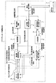
図1に示すように、本実施例の超音波アクチュエータ駆動装置は、超音波アクチュエータ駆動回路1と、この超音波アクチュエータ駆動回路1によって駆動が制御される超音波アクチュエータ2とを有している。
前記超音波アクチュエータ駆動回路1は、前記超音波アクチュエータ2を駆動する回路であり、発振回路3、電力増幅回路4、電流検出回路5、位相差検出回路6、電流振幅検出回路7、比較回路8、周波数領域検出回路9、モード制御回路10、及び周波数制御回路11を有し、前記超音波アクチュエータ2は、前記電流検出回路5を介して前記電力増幅回路4に接続されている。
As shown in FIG. 1, the ultrasonic actuator driving apparatus of this embodiment includes an ultrasonic
The ultrasonic
ここで、前記超音波アクチュエータ2の構成について説明する。
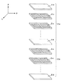
本実施例の超音波アクチュエータ駆動装置は、例えば図2(a)に示す超音波アクチュエータ2を備えている。この超音波アクチュエータ2は、図2(a)、図2(b)に示すように、角柱形状の圧電積層体で構成された超音波振動子2Aと、この超音波振動子2Aの圧電積層体の後述する摩擦部材13を介して接触するように配設された被駆動部2Bと、前記超音波振動子2Aの圧電積層体の左右両側側面それぞれ2箇所に設けられた外部電極12と、前記超音波振動子2Aの圧電積層体の例えば底面の2箇所に接着された摩擦部材13と、を有している。また、超音波振動子2Aには、所定の押圧手段(図示せず)によって所定の押圧力が加えられている。
Here, the configuration of the
The ultrasonic actuator driving apparatus of the present embodiment includes, for example, an
このような超音波振動子2Aを用いた場合、超音波振動子2Aに加える押圧力の大きさが変化すると、超音波振動子2Aの変位量−周波数特性は変化する。すなわち、図22(a)及び図22(b)に示すように、押圧力が0kgf、1kgf、2kgfと大きくなるにしたがって、変位量−周波数特性は、全体的に変位量が小さくなりかつ高周波数側にシフトしていく。また、変位量−周波数特性は、縦1次振動モードと屈曲2次振動モードとで、上述した高周波数側へのシフトの度合いが異なっている。本実施例では、角柱形状の圧電積層体の縦横寸法比を所定の値に設定することにより、ある所定の押圧力の下で、縦1次振動モードと屈曲2次振動モードの共振周波数が一致するように構成している。
When such an
前記超音波振動子2Aの圧電積層体は、図4に示すように内部電極処理が施された薄い矩形状の圧電板2cをY軸方向(超音波振動子2Aの振動方向に対し直交する超音波振動子2Aの奥行き方向)に積層して一体に構成されている。
As shown in FIG. 4, the piezoelectric laminated body of the
図中右側の外部電極12は、前記超音波振動子2Aの圧電積層体の図中右側面部から取り出されている内部電極露出部(図示せず)に取付けることにより、2つの電気端子(A+,A−の両端子)をA(A相)として構成している。また、図中左側の外部電極12は、前記圧電積層体の図中左側側面部から取り出されている内部電極露出部(図示せず)に取付けることにより、2つの電気端子(B+,B−の両端子)をB(B相)として構成している。この場合、A−,B−端子については、それぞれA相,B相のグラウンドとして構成しているので、リード線等で電気的に同電位となるように構成しても良い。
The
これらの外部電極12には、図示はしないがそれぞれリード線が半田等で接続されており、これらリード線は、前記電流検出回路5に接続されるようになっている。
前記摩擦部材13は、被駆動部2Bに接触する前記圧電積層体の底面に発生する屈曲振動の腹の位置にそれぞれ設けられている。
なお、本構成例では、前記超音波振動子2Aは、長手方向の寸法が例えば5〜20mmとなるよう構成することが望ましい。また、この超音波振動子2A及び前記被駆動部2Bを含めて超音波アクチュエータ2を構成する際に加える押圧力は、例えば0.1〜3kgfであることが望ましい。
Although not shown, lead wires are connected to these
The
In the present configuration example, it is desirable that the
上記構成例によれば、効率の良い状態で駆動するのに好適な超音波アクチュエータ2を得ることができ、また、上記構成の超音波振動子2Aを利用することにより、部品点数を少なくすることが可能であり、個体のばらつきも抑えることが可能である。また、超音波振動子2AのQ値が一定値となるように設計することで、ある所定の押圧力の下で縦1次振動モードと屈曲2次振動モードの共振周波数が一致するので、上述した共振周波数検出処理ルーチンをより効果的に実行することが可能になる。
According to the above configuration example, the
なお、本構成例では、超音波振動子2Aの外部電極12が圧電積層体の外部表面として該圧電積層体の長手方向の両側面に配置したが、これに限定するものではなく、図3の第1変形例に示すように、外部電極12を側面側から引き出して前記圧電積層体の表面に形成しても良く、また、前記圧電積層体の裏面の対応する位置に配置しても良い。
In this configuration example, the
また、本実施例においては、前記超音波振動子2Aの圧電積層体の積層方向は、Y軸方向に積層されているものとして説明したが、これに限定するものではなく、図5に示すように、超音波振動子2Aの圧電積層体の略上半分の積層体である第1の圧電積層体2aと、略下半分の積層体である第2の圧電積層体2bとが、絶縁圧電シート2dを介して、Z軸方向(前記超音波振動子2Aの駆動方向に対し垂直な垂直方向)に積層された構成としても良い。さらに、図6に示すように、前記圧電積層体の略左半分の積層体である第1の圧電積層体2aと、略右半分の積層体である第2の圧電積層体2bとが絶縁圧電シート2dを介してX軸方向(前記超音波振動子2Aの駆動方向と同じ水平方向)に積層された構成にすることも可能である。
In the present embodiment, the piezoelectric laminate of the
さらに、また、前記第1実施例及び前記第1変形例の超音波アクチュエータ2は、圧電積層体を図示しない絶縁層を介して一体に構成したことについて説明したが、これに限定するものではなく、図7の第2変形例に示すように角柱形状の基本弾性体18の長手方向に対し並列に固定された少なくとも2つの積層型圧電素子17Aと、前記基本弾性体18に対しこれら2つの前記積層型圧電素子17Aを押圧挟持する保持用弾性体17Bと、被駆動部である接触部19に接触する前記基本弾性体18の面に発生する屈曲振動の腹の位置に設けた摩擦部材13と、を有する超音波振動子を用いて前記超音波アクチュエータ2Cとして構成しても良い。
図8に上述した超音波アクチュエータ2の特性が示されている。すなわち、この超音波アクチュエータ2は、図8(a)に示す速度と周波数特性において、周波数fを共振周波数(図8(a)中の点線で示す部分)より低い周波数領域で駆動を行うと急激に速度が低下し、逆に、周波数fを共振周波数より高い周波数領域で駆動を行うと徐々に速度が低下して、ある地点で急激に速度が低下する特性を有している。
また、この超音波アクチュエータ2は、その速度−周波数特性が周波数の挿引方向によってほとんど変化せず、ヒステリシス現象がほとんど発生しない。すなわち、この超音波アクチュエータ2は、図23に示すように、周波数を共振周波数より高い方から低い方へ挿引して得られる速度−周波数特性と共振周波数より低いほうから高い方へ挿引して得られるそれぞれの速度−周波数特性にほとんど差が見られない。
また、その速度−周波数特性と併せて、この超音波アクチュエータ2は、図8(b)に示すような電圧−電流位相差と周波数特性では、共振周波数付近で位相差が急激に変化する特性、及び、周波数の掃引方向に拠らない特性を有している。また、超音波アクチュエータ2は、図8(c)に示す駆動電流−周波数特性において、共振周波数付近では位相差を検出するの十分な電流が流れるが、共振周波数より離れると電流振幅が減少し、図8(d)に示すように、位相差を正確に検出することが困難になる。
Furthermore, in the
FIG. 8 shows the characteristics of the
In addition, the
In addition to the velocity-frequency characteristics, this
そこで、本実施例の超音波アクチュエータ駆動装置は、このような特性の有する超音波アクチュエータ2の超音波振動子2Aに対し、前記超音波アクチュエータ駆動回路1によって正確に位相検出を行い、確実に共振周波数近傍の交番信号を印加すれば、駆動効率の良い状態でこの超音波アクチュエータ2を駆動させることができる。
Therefore, the ultrasonic actuator driving apparatus of the present embodiment accurately detects the phase by the ultrasonic
次に、本実施例の超音波アクチュエータ駆動回路1の構成について図1を参照しながら説明する。
図1に示すように、超音波アクチュエータ駆動回路1において、前記駆動回路としての発振回路3は、周波数制御回路11より出力される周波数制御信号11aにより決定される周波数の交番信号3aを生成する回路で、生成した交番信号3aを電力増幅回路4に供給する。
Next, the configuration of the ultrasonic
As shown in FIG. 1, in the ultrasonic
電力増幅回路4は、前記交番信号3aを電力増幅し駆動電圧信号4aを出力する回路で、増幅した駆動電圧信号4aを電流検出回路を介して前記超音波アクチュエータ2に供給する。これにより、前記超音波アクチュエータ2は、供給された駆動電圧信号4aに基づき駆動されるようになっている。
The
電流検出回路5は、前記駆動電圧信号4aを前記超音波アクチュエータ2に印加した際に流れる電流を検出し駆動電流検出信号5aとして出力する回路で、検出した駆動電流検出信号5aを位相差検出回路6及び電流振幅検出回路7に供給する。
The
位相差検出回路6は、前記駆動電圧信号4aと前記駆動電流検出信号5aとの位相差を検出し位相差検出信号6aを出力する回路で、検出した位相差検出信号6aを前記周波数制御回路11に供給する。
The phase
電流振幅検出回路7は、前記駆動電流検出信号5aの振幅を検出する回路で、検出した振幅結果信号7aを比較回路8の一方の入力端に供給する。この比較回路8の他方の入力端には、入力端子8Aに接続される図示しない駆動電流閾値信号発生手段から比較処理を行うための基準となる駆動電流閾値信号8a1が供給されるようになっている。
比較回路8は、前記電流振幅検出回路7の振幅結果信号7aが所定の値である駆動電流閾値信号8a1を超えたときに電流振幅条件信号8aを出力する回路で、この電流振幅条件信号8aを周波数領域検出回路9に供給する。
The current
The
周波数領域検出回路9は、後述するモード制御回路10からの上方掃引制御信号10aが入力される状態では、電流振幅条件信号8aが入力され始める時点の周波数制御信号を下限周波数信号9bとして出力し、前記モード制御回路10からの下方掃引制御信号10bが入力される状態では、電流振幅条件信号8aが入力され始める時点の周波数制御信号を上限周波数信号9aとして出力する回路である。この周波数領域検出回路9は、前記上限周波数信号9a及び前記下限周波数信号9bをモード制御回路10及び周波数制御回路11に供給する。
In a state where the upward sweep control signal 10a from the
モード制御回路10と周波数制御回路11は、本実施例の超音波アクチュエータ駆動回路1全体を制御する制御手段(制御回路)である。
モード制御回路10は、前記超音波アクチュエータ2の駆動開始前に上方掃引制御信号10aを出力し、周波数領域検出回路9より前記下限周波数信号9bが出力された後は前記上方掃引制御信号10aの出力を停止するとともに下限掃引制御信号10bを出力する。そして、モード制御回路10は、周波数領域検出回路9より前記上限周波数信号9aが出力された後は下限掃引制御信号10bの出力を停止するとともに周波数追尾制御信号10cを出力する。このモード制御回路10は、前記上方掃引制御信号10a、前記下方掃引制御信号10b及び周波数追尾制御信号10cを前記周波数制御回路11に供給する。
The
The
周波数制御回路11は、上方掃引制御信号10aが入力される状態では、交番信号3aの周波数が下方から上方へ変化するように周波数制御信号11aを変化させる。また、周波数制御回路11は、下方掃引制御信号10bが入力される状態では、交番信号3aの周波数が上方から下方へ変化するように周波数制御信号11aを変化させる。また、周波数制御回路11は、周波数追尾制御信号10cが入力される状態では、前記上限周波数信号9aと前記下限周波数信号9bとで定義される周波数領域内で、周波数に対する前記位相差検出信号6aの変化量が最大となる周波数を検出し、前記周波数の検出が終了した後は、駆動周波数を検出した前記周波数に設定するように制御する。
In a state where the upper sweep control signal 10a is input, the
なお、前記電流振幅検出回路7は、駆動電流検出信号5aの振幅を検出する構成としたが、駆動電圧信号4aの振幅と駆動電流検出信号5aの振幅の比を検出する構成や、超音波アクチュエータ2のアドミッタンスを導出する構成を採用することも可能である。
また、前記位相差検出回路6は、前記駆動電圧信号4aと前記駆動電流検出信号5aの位相差を出力する構成としたが、前記交番信号3aと前記駆動電流検出信号5aの位相差を出力する構成を採用することも可能である。
The current
The phase
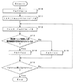
次に、本実施例の超音波アクチュエータ駆動回路1の作用について図9及び図15を参照しながら説明する。なお、図15は本発明の超音波アクチュエータ駆動方法を実行した際の周波数制御回路全体の動作の流れを示すフローチャートである。
上記構成の超音波アクチュエータ駆動回路1において、前記周波数制御回路11は、図9(a)に示すように、駆動初期には、駆動電圧信号の周波数を下方から上方へ掃引し、駆動電流の振幅(振幅結果信号7a)が駆動電流閾値信号8a1で定義される値を超える周波数領域の下限値を検出するように制御する(ステップS100)。
Next, the operation of the ultrasonic
In the ultrasonic
次に、周波数制御回路11は、図9(b)に示すように駆動電圧信号4aの周波数を上方から下方へ掃引し、駆動電流の振幅(振幅結果信号7a)が駆動電流閾値信号8a1で定義される値を超える周波数領域の上限値を検出するように制御する(ステップS101)。
Next, as shown in FIG. 9B, the
ここで、前記駆動電流閾値信号8a1は、駆動電圧信号4aと駆動電流検出信号5aの位相差が正確に求めることができる最小の電流振幅値に相当する値に設定すると良い。 Here, the drive current threshold signal 8a1 may be set to a value corresponding to the minimum current amplitude value that can accurately obtain the phase difference between the drive voltage signal 4a and the drive current detection signal 5a.
最後に、周波数制御回路11は、図9(c)に示すように、検出された周波数領域L3の上限値と下限値の間で、周波数に対する位相差検出信号6aの変化量が最大となる周波数を検出し(ステップS102)、検出が終了した後に駆動周波数を検出した周波数に設定するように制御する(ステップS103)。
Finally, as shown in FIG. 9C, the
次に、周波数に対する位相差検出信号6aの変化量が最大となる周波数の検出方法(図15中のステップS102による検出処理方法)について図10及び図11を参照しながら説明する。 Next, a frequency detection method (detection processing method in step S102 in FIG. 15) that maximizes the amount of change in the phase difference detection signal 6a with respect to the frequency will be described with reference to FIGS.
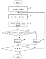
いま、本実施例の超音波アクチュエータ駆動装置の駆動方法を実行すると、前記周波数制御回路11は、図11に示す共振周波数検出処理ルーチンを起動し、ステップS1以下、ステップS7までの処理を実行する。
Now, when the driving method of the ultrasonic actuator driving apparatus of the present embodiment is executed, the
ステップS1では、周波数制御回路11は、図10(a)に示す電圧−電流の位相差の特性から検出された共振周波数を含む周波数領域(上限値をfmax、下限値をfminとする領域)の上限値fmaxを周波数f2に代入し、下限値fminを周波数f1に代入する。
In step S1, the
そして、周波数制御回路11は、続くステップS2の処理で、周波数f1と周波数f2の中間値(f1+f2)/2を算出し、周波数fcに代入する。
Then, the
次に、周波数制御回路11は、ステップS3の処理で、前記周波数f1、周波数f2及び周波数fcのそれぞれの周波数に対応する電圧−電流の位相差(以下、位相差と称す)を検出し、周波数f1で検出した位相差をph(f1)、周波数f2で検出した位相差をph(f2)とし、周波数fcで検出した位相差をph(fc)へそれぞれ代入する。
Next, the
その後、周波数制御回路11は、ステップS4の判断処理にて、|ph(fc)−ph(f1)|と、|ph(f2)−ph(fc)|とを比較する。ここで、|ph(f2)−ph(fc)|が小さい場合には、続くステップS5の処理にて周波数f2を周波数fcの値に置き換えて、続くステップS7の処理に移行する。|ph(fc)−ph(f1)|が小さい場合には、ステップS6の処理にて周波数f1を周波数fcの値に置き換えて、ステップS7の処理に移行する。
Thereafter, the
なお、図10(b)では、|ph(f2)−ph(fc)|が小さい場合になるので、周波数制御回路11が実行する前記ステップS5の処理によって、周波数f2は周波数fcの値に置き換えられることになる。
In FIG. 10B, since | ph (f2) −ph (fc) | is small, the frequency f2 is replaced with the value of the frequency fc by the process of step S5 executed by the
その後、周波数制御回路11は、ステップS7の判断処理にて、前記周波数f1と前記周波数f2とが略等しいか否かを判定する。この場合、周波数制御回路11は、f1≒f2の関係を満足するものでなく、つまり、等しくないと判定した場合、前記ステップS2の処理に戻し、このステップS2の処理を再度継続して行う。
Thereafter, the
一方、周波数制御回路11は、前記ステップS7の判断処理にて、f1≒f2の関係を満足するもので略等しいと判定した場合には、f1≒f2になる関係を満足することを認識するとともに、このときの周波数値を超音波振動子2Aが駆動するのに好適の共振周波数近傍値として設定し、この共振周波数検出処理ルーチンを終了させる。
On the other hand, the
したがって、周波数制御回路11は、前記ステップS2〜前記ステップS6の処理を、f1≒f2になる関係を満足するまで繰り返し実行することにより、前記共振周波数近傍を高精度に検出することが可能となる。
Therefore, the
したがって、本実施例によれば、以上の動作により、駆動電流が小さいために駆動電圧と駆動電流の位相差が正確に求めることが出来ない領域を回避して確実に共振周波数近傍の周波数に駆動周波数が設定されるので、駆動効率の良い超音波アクチュエータ2の駆動を行うことが可能となる。
なお、本実施形態では、上方掃引の後に下方掃引を行うように制御したが、下方掃引を最初に行い、その後に上方掃引を行うよう制御しても、上記実施例と同様の効果を得ることができる。
また、本実施形態では、アクチュエータ駆動回路1を全て回路で構成した場合について説明したが、これに限定されることはなく、マイコンなどを用いてソフトウェアで構成することも可能である。その場合、周波数制御回路11,周波数領域検出回路9,モード制御回路10等をソフト的に置き換えた構成を採用すれば良い。
Therefore, according to the present embodiment, the above operation avoids the region where the phase difference between the drive voltage and the drive current cannot be obtained accurately because the drive current is small, so that the drive is surely performed at a frequency near the resonance frequency. Since the frequency is set, it is possible to drive the
In this embodiment, the control is performed so that the downward sweep is performed after the upward sweep. However, even if the downward sweep is performed first and then the upward sweep is performed, the same effect as in the above embodiment can be obtained. Can do.
Further, in the present embodiment, the case where the
図12乃至図15は本発明の超音波アクチュエータ駆動方法の第2実施例を示し、図12は超音波アクチュエータ駆動方法を実現する超音波アクチュエータ駆動装置の全体構成を示すブロック図、図12乃至図15は本実施例の超音波アクチュエータ駆動方法を説明するためのもので、図13は周波数制御回路による下限周波数の検出方法を説明するグラフであり、図13(a)は発振回路の設定可能な周波数範囲を説明する駆動電流振幅と周波数との特性を示すグラフ、図13(b)は周波数範囲の下限周波数の検出方法を説明する駆動電流振幅と周波数との特性を示すグラフである。また、図14は図12の周波数制御回路による下限周波数検出処理ルーチンの制御例を示すフローチャートであり、図15は本発明の超音波アクチュエータ駆動方法を実行した際の周波数制御回路全体の動作の流れを示すフローチャートである。なお、図15は前記第1実施例及び第2実施例共通である。また、図12は前記第1実施例と同様に構成要素については同一の符号を付して説明を省略し、異なる部分のみを説明する。 12 to 15 show a second embodiment of the ultrasonic actuator driving method of the present invention. FIG. 12 is a block diagram showing the overall configuration of the ultrasonic actuator driving apparatus for realizing the ultrasonic actuator driving method. 15 is a graph for explaining the ultrasonic actuator driving method of this embodiment. FIG. 13 is a graph for explaining the detection method of the lower limit frequency by the frequency control circuit. FIG. FIG. 13B is a graph showing the characteristics of the drive current amplitude and frequency for explaining the detection method of the lower limit frequency of the frequency range, and FIG. 13B is a graph showing the characteristics of the drive current amplitude and frequency for explaining the frequency range. FIG. 14 is a flowchart showing a control example of the lower limit frequency detection processing routine by the frequency control circuit of FIG. 12, and FIG. 15 is a flow of operations of the entire frequency control circuit when the ultrasonic actuator driving method of the present invention is executed. It is a flowchart which shows. FIG. 15 is common to the first and second embodiments. Further, in FIG. 12, like the first embodiment, the same reference numerals are given to the constituent elements and the description thereof is omitted, and only different parts will be described.
本実施例の超音波アクチュエータ駆動装置は、超音波アクチュエータ駆動回路1Aと、超音波アクチュエータ2を有している。この超音波アクチュエータ2は前記第1実施例と同様である。また、前記超音波アクチュエータ駆動回路1Aは、前記第1実施例における周波数領域検出回路9を削除している。
The ultrasonic actuator driving apparatus of the present embodiment includes an ultrasonic actuator driving circuit 1A and an
図12に示すように、超音波アクチュエータ駆動回路1Aにおいて、前記発振回路3は、周波数制御回路11Aより出力される周波数制御信号11aにより決定される周波数の交番信号3aを生成する回路で、生成した交番信号3aを電力増幅回路4に供給する。
As shown in FIG. 12, in the ultrasonic actuator driving circuit 1A, the
電力増幅回路4は、前記交番信号3aを電力増幅し駆動電圧信号4aを出力する回路で、増幅した駆動電圧信号4aを電流検出回路を介して前記超音波アクチュエータ2に供給する。これにより、前記超音波アクチュエータ2は、供給された駆動電圧信号4aに基づき駆動されるようになっている。
The
電流検出回路5は、前記駆動電圧信号4aを前記超音波アクチュエータ2に印加した際に流れる電流を検出し駆動電流検出信号5aとして出力する回路で、検出した駆動電流検出信号5aを位相差検出回路6及び電流振幅検出回路7に供給する。
The
位相差検出回路6は、前記駆動電圧信号4aと前記駆動電流検出信号5aとの位相差を検出し位相差検出信号6aを出力する回路で、検出した位相差検出信号6aを前記周波数制御回路11Aに供給する。
The phase
電流振幅検出回路7は、前記駆動電流検出信号5aの振幅を検出する回路で、検出した振幅結果信号7aを比較回路8の一方の入力端に供給する。この比較回路8の他方の入力端には、入力端子8Aに接続される図示しない駆動電流閾値信号発生手段から比較処理を行うための基準となる駆動電流閾値信号8a1が供給されるようになっている。
比較回路8は、前記電流振幅検出回路7の振幅結果信号7aが所定の値である駆動電流閾値信号8a1を超えたときに電流振幅条件信号8aを出力する回路で、この電流振幅条件信号8aを周波数制御回路11Aに供給する。
The current
The
モード制御回路10Aと周波数制御回路11Aは、本実施例の超音波アクチュエータ駆動回路1A全体を制御する制御手段である。
モード制御回路10Aは、前記超音波アクチュエータ2の駆動開始前に下限周波数検出制御信号10eを出力し、周波数制御回路11Aより動作完了信号11bが入力された後は前記下限周波数検出制御信号10eの出力を停止するとともに上限周波数検出制御信号10dを出力する。そして、モード制御回路10Aは、周波数制御回路11Aより前記動作完了信号11bが入力された後は前記上限周波数検出制御信号10dの出力を停止するとともに周波数追尾制御信号10fを出力する。このモード制御回路10Aは、前記下限周波数検出制御信号10e、前記上限周波数検出制御信号10d及び周波数追尾制御信号10fを前記周波数制御回路11Aに供給する。
The
The
周波数制御回路11Aは、下限周波数検出制御信号10eが入力される状態では、周波数を離散的に変化させながら電流振幅条件信号8aが出力される下限周波数を検出する。また、周波数制御回路11Aは、上限周波数検出制御信号10dが入力される状態では、周波数を離散的に変化させながら電流振幅条件信号8aが出力される上限周波数を検出する。また、周波数制御回路11Aは、周波数追尾制御信号10fが入力される状態では、前記上限周波数と前記下限周波数とで定義される周波数領域内で、周波数に対する前記位相差検出信号6aの変化量が最大となる周波数を検出し、前記周波数の検出が終了した後は、駆動周波数を検出した前記周波数に設定するように制御する。
その他の構成については、前記第1実施例と同様である。
In a state where the lower limit frequency detection control signal 10e is input, the
Other configurations are the same as those in the first embodiment.
次に、本実施例の超音波アクチュエータ駆動回路1Aの作用について図15を参照しながら説明する。
上記構成の超音波アクチュエータ駆動回路1Aにおいて、前記周波数制御回路11Aは、駆動初期には、駆動電流の振幅(振幅結果信号7a)が駆動電流閾値信号8a1で定義される値を超える周波数領域の下限周波数(下限値)を検出するように制御する(ステップS100)。
Next, the operation of the ultrasonic actuator drive circuit 1A of the present embodiment will be described with reference to FIG.
In the ultrasonic actuator drive circuit 1A having the above-described configuration, the
次に、周波数制御回路11Aは、駆動電流の振幅(振幅結果信号7a)が駆動電流閾値信号8a1で定義される値を超える周波数領域の上限周波数(上限値)を検出するように制御する(ステップS101)。
ここで、前記駆動電流閾値信号8a1は、駆動電圧信号4aと駆動電流検出信号5aの位相差が正確に求めることができる最小の電流振幅値に相当する値に設定すると良い。
Next, the
Here, the drive current threshold signal 8a1 may be set to a value corresponding to the minimum current amplitude value that can accurately obtain the phase difference between the drive voltage signal 4a and the drive current detection signal 5a.
そして、周波数制御回路11Aは、検出された周波数領域L3(図9(c)参照)の上限値と下限値の間で、周波数に対する位相差検出信号6aの変化量が最大となる周波数を検出する(ステップS102)。
Then, the
最後に、周波数制御回路11Aは、駆動周波数を、前記ステップS102の処理で検出した周波数に設定するように制御する。
Finally, the
次に、前記ステップS100よる下限周波数の検出処理方法について図13及び図14を参照しながら説明する。 Next, the lower limit frequency detection processing method in step S100 will be described with reference to FIGS.
いま、本実施例の超音波アクチュエータ駆動装置の駆動方法を実行し、図15中のステップS100の処理を実行すると、前記周波数制御回路11Aは、図14に示す下限値検出処理ルーチンを起動し、ステップS10以下、ステップS17までの処理を実行する。
Now, when the method of driving the ultrasonic actuator driving apparatus of the present embodiment is executed and the processing of step S100 in FIG. 15 is executed, the
ステップS10では、周波数制御回路11Aは、発振回路3の設定可能な周波数領域(上限値をfmax、下限値をfminとする領域:図13(a)参照)の下限値fminを周波数faに代入する。
In step S10, the
そして、周波数制御回路11Aは、続くステップS11の処理で、上限値fmaxと下限値fminの中間値(fmax+fmin)/2を周波数fbに代入し(図13(b)参照)、ステップS12に移行する。
その後、周波数制御回路11Aは、ステップS12の処理で、周波数faと周波数fbの中間値(fa+fb)/2を周波数fccに代入し、ステップS13に移行する。
次に、周波数制御回路11Aは、ステップS13の判断処理にて、周波数fccで駆動した時に、電流振幅条件信号8aが出力されているか否かを判断する。この場合、前記周波数制御回路11Aは、図13(b)に示すように、前記電流振幅条件信号8aが出力されていないと判断した場合には、続くステップS15の処理にて、周波数faを周波数fccに置き換えて、ステップS16の判断処理に移行する。一方、周波数制御回路11Aは、前記電流振幅条件信号8aが出力されていると判断した場合には、続くステップS14の処理にて、周波数fbを周波数fccに置き換えて、ステップS16の判断処理に移行する。
The
Thereafter, the
Next, the
ステップS16の判断処理では、周波数制御回路11Aは、前記周波数faと前記周波数fccとが略等しいか否か、もしくは前記周波数fbが前記周波数fccとが略等しいか否かを判定する。この場合、周波数制御回路11Aは、fa≒fccもしくはfb≒fccの関係を満足するものでなく、つまり、等しくないと判定した場合、前記ステップS12の処理に戻し、このステップS12の処理を再度継続して行う。
In the determination process of step S16, the
一方、周波数制御回路11Aは、前記ステップS16の判断処理にて、fa≒fccもしくはfb≒fccの関係を満足するもので略等しいと判定した場合には、fa≒fccもしくはfb≒fccになる関係を満足することを認識するとともに、このときの周波数値fccを下限周波数(下限値)として設定し、この下限値検出処理ルーチンを終了させる。
On the other hand, when the
したがって、周波数制御回路11Aは、前記ステップS12〜前記ステップS16の処理を、fa≒fccもしくはfb≒fccになる関係を満足するまで繰り返し実行することにより、駆動電流の振幅(振幅結果信号7a)が駆動電流閾値信号8a1で定義される値を超える周波数領域の下限周波数(下限値)を高精度に検出することが可能となる。
Therefore, the
なお、本実施例では、上述した周波数制御回路11Aによる制御例は、下限値の周波数検出処理について説明したが、これに限定されるものではなく、図15中のステップS101に示す上限値の周波数検出処理についても同様に行うように制御しても良い。また、本実施例の周波数制御回路11Aは、周波数に対する位相差検出信号6aの変化量が最大となる周波数の検出方法については、前記第1実施例と同様に制御する。
In the present embodiment, the control example by the
したがって、本実施例によれば、前記第1実施例と同様に、駆動電流が小さいために駆動電圧と駆動電流の位相差が正確に求めることができない領域を回避して確実に共振周波数近傍の周波数に駆動周波数が設定されるので、駆動効率の良い超音波アクチュエータ2の駆動を行うことが可能となる。
なお、本実施形態では、下限周波数検出処理(図15のステップS100の処理)の後に上限周波数検出処理(図15のステップS101の処理)を行うように制御したが、前記上限周波数検出処理を最初に行い、その後に前記下限周波数検出処理を行うよう制御しても、上記実施例と同様の効果を得ることができる。
また、本実施形態では、アクチュエータ駆動回路1Aを全て回路で構成した場合について説明したが、これに限定されることはなく、マイコンなどを用いてソフトウェアで構成することも可能である。その場合、周波数制御回路11A,モード制御回路10A等をソフト的に置き換えた構成を採用すれば良い。
Therefore, according to the present embodiment, as in the first embodiment, the region where the phase difference between the drive voltage and the drive current cannot be accurately obtained due to the small drive current is avoided to ensure that the resonance frequency is near the resonance frequency. Since the driving frequency is set to the frequency, it is possible to drive the
In the present embodiment, control is performed so that the upper limit frequency detection process (the process of step S101 of FIG. 15) is performed after the lower limit frequency detection process (the process of step S100 of FIG. 15). Even if it controls to perform the said lower limit frequency detection process after that, the effect similar to the said Example can be acquired.
Further, in the present embodiment, the case where the actuator drive circuit 1A is entirely configured has been described, but the present invention is not limited to this, and the actuator drive circuit 1A can also be configured by software using a microcomputer or the like. In that case, a configuration in which the
図16乃至図19は本発明の超音波アクチュエータ駆動方法の第3実施例を示し、図16は超音波アクチュエータ駆動方法を実現する超音波アクチュエータ駆動装置の全体構成を示すブロック図、図17(a)及び図17(b)は本実施例に係る超音波アクチュエータ駆動装置に用いられる超音波アクチュエータの構成例を示すもので、図17(a)は正面図、図17(b)は側面図、図18は本実施例の超音波アクチュエータの第1変形例を示す側面図、図19は本実施例の超音波アクチュエータの第2変形例を示す正面図、図20は本実施例の超音波アクチュエータ駆動方法を説明するためのグラフであり、図20(a)は駆動電流振幅と周波数との特性を示すグラフ、図20(b)は周波数設定信号と周波数との特性を示すグラフ、図20(c)は設定が禁止される周波数範囲を説明する位相差検出信号と周波数との特性を示すグラフである。なお、図16乃至図19は前記第1実施例と同様に構成要素については同一の符号を付して説明を省略し、異なる部分のみを説明する。 FIGS. 16 to 19 show a third embodiment of the ultrasonic actuator driving method of the present invention. FIG. 16 is a block diagram showing the overall configuration of the ultrasonic actuator driving device for realizing the ultrasonic actuator driving method. FIG. ) And FIG. 17B show a configuration example of the ultrasonic actuator used in the ultrasonic actuator driving apparatus according to the present embodiment, FIG. 17A is a front view, FIG. 17B is a side view, 18 is a side view showing a first modification of the ultrasonic actuator of the present embodiment, FIG. 19 is a front view showing a second modification of the ultrasonic actuator of the present embodiment, and FIG. 20 is an ultrasonic actuator of the present embodiment. FIG. 20A is a graph for explaining a driving method, FIG. 20A is a graph showing characteristics of drive current amplitude and frequency, FIG. 20B is a graph showing characteristics of frequency setting signal and frequency, and FIG. 0 (c) is a graph showing the characteristics of the phase difference detection signal and frequency to explain frequency range setting is inhibited. 16 to 19, like the first embodiment, the same reference numerals are given to the components and the description thereof will be omitted, and only different parts will be described.
本実施例の超音波アクチュエータ駆動装置は、超音波アクチュエータ駆動回路1Bと、超音波アクチュエータ2Dを有している。なお、本実施例の超音波アクチュエータ駆動装置は、前記超音波アクチュエータ2Dの構成が前記第1実施例とは異なり、また、前記超音波アクチュエータ駆動回路1Bについては、前記第1実施例の構成要素である周波数領域検出回路9及びモード制御回路10を削除し、新たに位相差条件判定回路14を設けて構成したことが前記第1実施例とは異なっている。
The ultrasonic actuator driving apparatus of the present embodiment includes an ultrasonic actuator driving circuit 1B and an
図16に示すように、アクチュエータ駆動回路1Bは、前記超音波アクチュエータ2Dを駆動する回路であり、発振回路3、電力増幅回路4、電流検出回路5、位相差検出回路6、電流振幅検出回路7、比較回路8A、周波数制御回路11B、位相差条件判定回路14を有し、前記超音波アクチュエータ2Dは電流検出回路5を介して前記電力増幅回路4に接続されている。
As shown in FIG. 16, the actuator drive circuit 1B is a circuit for driving the
ここで、本実施例に用いられる前記超音波アクチュエータ2Dの構成について説明する。
本実施例の超音波アクチュエータ駆動装置は、例えば図17(a)に示す超音波アクチュエータ2Dを備えている。この超音波アクチュエータ2Dは、図17(a)、図17(b)に示すように、超音波振動子2Aを構成する圧電積層体の上面及び底面に少なくとも2箇所ずつに摩擦部材13を設けるとともに、この圧電積層体に所定の押圧力を与えながら挟持する第1のガイド15及び第2のガイド16を有している。また、超音波振動子2Aには、前記ガイド11、12などを含む所定の押圧手段(図示せず)によって所定の押圧力が加えられている。
Here, the configuration of the
The ultrasonic actuator driving apparatus of this embodiment includes an
このような超音波振動子2Aを用いた場合においても同様に、超音波振動子2Aに加える押圧力の大きさが変化すると、超音波振動子2Aの変位量−周波数特性は変化する。すなわち、図22(a)及び図22(b)に示すように、押圧力が0kgf、1kgf、2kgfと大きくなるにしたがって、変位量−周波数特性は、全体的に変位量が小さくなりかつ高周波数側にシフトしていく。また、変位量−周波数特性は、縦1次振動モードと屈曲2次振動モードとで、上述した高周波数側へのシフトの度合いが異なっている。本実施例では、角柱形状の圧電積層体の縦横寸法比を所定の値に設定することにより、ある所定の押圧力の下で、縦1次振動モードと屈曲2次振動モードの共振周波数が一致するように構成している。
Similarly, when such an
なお、前記摩擦部材13は、超音波アクチュエータ2Dが最も高レベルの出力特性を得ることができる任意の位置、すなわち、超音波振動子2Aの最も高レベルの超音波楕円振動が行われる位置に設けるのが望ましい。一般には、楕円振動を行うことが駆動の源となるため、少なくとも1個以上の摩擦部材13では図17中に示す矢印のように楕円振動が起こっており、全ての摩擦部材13の部位で生ずる振動による駆動力の総和が0にならないように前記摩擦部材13を配置すれば良い。
The
なお、本構成例では、前記超音波振動子2Aは、長手方向の寸法が例えば5〜20mmとなるよう構成することが望ましい。また、この超音波振動子2A及び前記第1、第2のガイド15,16を含めて超音波アクチュエータ2Dを構成する際に加える押圧力は、例えば30gf〜100gfであることが望ましい。
また、本構成例の超音波アクチュエータ2Dの特性及び前記超音波振動子2Aの圧電積層体の積層方向は、前記第1実施例と略同様である。
In the present configuration example, it is desirable that the
The characteristics of the
本実施例の超音波アクチュエータ2Dは、前記超音波アクチュエータ駆動装置によって交番信号の駆動信号が印加されると、超音波振動子2Aの摩擦部材13近傍で楕円振動が生じることにより、この超音波振動子2Aが前記第1及び第2のガイド15,16にガイドされながら左右に駆動する。
その他の作用については、前記第1実施例(図2参照)と同様である。
In the
Other operations are the same as those in the first embodiment (see FIG. 2).
上記構成例によれば、効率の良い状態で駆動するのに好適な超音波アクチュエータ2Dを得ることができ、また、上記構成の超音波振動子2Aを利用することにより、部品点数を少なくすることが可能であり、個体のばらつきも抑えることが可能である。また、超音波振動子2AのQ値が一定値となるように設計することで、ある所定の押圧力の下で縦1次振動モードと屈曲2次振動モードの共振周波数が一致するので、上述した共振周波数検出処理ルーチンをより効果的に実行することが可能になる。
According to the above configuration example, an
なお、本実施例では、超音波振動子2Aの外部電極12が圧電積層体の外部表面として該圧電積層体の長手方向の両側面に配置したが、これに限定するものではなく、図19の第2変形例に示すように、外部電極12を側面側から引き出して前記圧電積層体の表面に形成しても良く、また、前記圧電積層体の裏面に対応する位置に配置しても良い。
In this embodiment, the
さらに、前記第1及び第2のガイド15,16は、図17(a)に示すように、角柱状に形成されたものについて説明したが、これに限定するものではなく、例えば図18の第1変形例に示すように、円柱状のものを用いても良いし、半円中状のものを用いても良い。前記摩擦部材13Aは、それに伴い、前記第1及び第2のガイド15A,16Aの形状に合わせてU字状、あるいはV字状に形成されたものを用いることが必要である。
Further, the first and
次に、本実施例の超音波アクチュエータ駆動回路1Bの構成について説明する。 Next, the configuration of the ultrasonic actuator drive circuit 1B of the present embodiment will be described.
図16に示すように、超音波アクチュエータ駆動回路1Bにおいて、前記発振回路3は、周波数制御回路11Bより出力される周波数制御信号11aにより決定される周波数の交番信号3aを生成する回路で、生成した交番信号3aを電力増幅回路4に供給する。
As shown in FIG. 16, in the ultrasonic actuator drive circuit 1B, the
電力増幅回路4は、前記交番信号3aを電力増幅し駆動電圧信号4aを出力する回路で、増幅した駆動電圧信号4aを電流検出回路を介して前記超音波アクチュエータ2に供給する。これにより、前記超音波アクチュエータ2Dは、供給された駆動電圧信号4aに基づき駆動されるようになっている。
The
電流検出回路5は、前記駆動電圧信号4aを前記超音波アクチュエータ2Dに印加した際に流れる電流を検出し駆動電流検出信号5aとして出力する回路で、検出した駆動電流検出信号5aを位相差検出回路6及び電流振幅検出回路7に供給する。
The
位相差検出回路6は、前記駆動電圧信号4aと前記駆動電流検出信号5aとの位相差を検出し位相差検出信号6aを出力する回路で、検出した位相差検出信号6aを位相差条件判定回路14に供給する。
The phase
位相差条件判定回路14は、周波数に対する前記位相差検出信号6aの変化量が所定の値を超えたときに位相差条件信号14aを出力する回路で、例えば図示はしないが微分回路や比較回路等を有しており、これらの回路により生成された前記位相差条件信号14aを前記周波数制御回路11Bに供給する。
The phase difference
電流振幅検出回路7は、前記駆動電流検出信号5aの振幅を検出する回路で、検出した振幅結果信号7aを比較回路8Aの一方の入力端に供給する。この比較回路8Aの他方の入力端には、入力端子8Aに接続される図示しない駆動電流閾値信号発生手段から比較処理を行うための基準となる駆動電流閾値信号8a1が供給されるようになっている。
比較回路8Aは、前記電流振幅検出回路7の振幅結果信号7aが所定の値である駆動電流閾値信号8a1を下回ったときに周波数設定禁止信号8bを出力する回路で、この周波数設定禁止信号8bを前記周波数制御回路11Bに供給する。
The current
The
周波数制御回路11Bは、本実施例の超音波アクチュエータ駆動回路1B全体を制御する制御手段である。この周波数制御回路11Bは、周波数を掃引し、比較回路8Aより周波数設定禁止信号8bが出力されておらず、且つ位相差条件判定回路14より位相差条件信号14aが出力される周波数を、駆動周波数に設定する回路である。
The
次に、本実施例の超音波アクチュエータ駆動回路1Bの作用について図20を参照しながら説明する。 Next, the operation of the ultrasonic actuator drive circuit 1B of the present embodiment will be described with reference to FIG.
上記構成の超音波アクチュエータ駆動回路1Bにおいて、前記周波数制御回路11Aは、例えば図20(a)に示す周波数を上方から下方へ一定の速度で掃引する。すると、このときの位相差検出信号6aは、前記周波数制御回路11Aによる周波数掃引に合わせて変化することになる。また、周波数掃引の速度は一定であるので、前記位相差条件判定回路14に含まれる図示しない微分回路により、前記位相差検出信号6aを微分することで、周波数に対する位相差検出信号6aの変化量を導くことができる。
よって、前記位相差条件判定回路14は、前記微分回路(図示せず)の出力を比較回路(図示しない)で比較することにより、周波数に対する位相差検出信号6aの変化量が所定の値を超えたか否かを検出することが出来る(図20(c)参照)。この検出結果、すなわち、前記比較回路(図示せず)の出力を位相差条件信号14aとして前記周波数制御回路11Bに供給すると、この周波数制御回路11Bは、図20(b)に示す周波数設定禁止信号8bがローレベルである有効期間において、前記位相差条件信号14aを認識して掃引を停止させ、共振周波数近傍の周波数を検出する。そして、周波数制御回路11Bは、前記第1実施例と同様にこの周波数を駆動周波数に設定する。
In the ultrasonic actuator drive circuit 1B configured as described above, the
Therefore, the phase difference
なお、本実施例では、前記周波数制御回路11Bは、図20(c)に示すように、駆動電流値が小さいため、位相を検出できない周波数領域では、前記比較回路8Aにより出力された前記周波数設定禁止信号8bを認識しているので、共振周波数と無関係の周波数に駆動周波数を設定しないように制御することができる。
In this embodiment, as shown in FIG. 20C, the
したがって、本実施例によれば、以上の動作により、駆動電流が小さいために駆動電圧と駆動電流の位相差が正確に求めることが出来ない領域を回避して確実に共振周波数近傍の周波数に駆動周波数が設定されるので、駆動効率の良い超音波アクチュエータ2の駆動を行うことが可能となる。
なお、本実施形態では、前記位相差条件判定回路14を微分回路と比較回路で構成した場合について説明したが、これに検定されるものではなく、離散的に周波数を走査し、その周波数に対する位相差検出信号を記憶し、周波数に対する前記位相差検出信号の変化量とその比較をソフトウェアで行う構成としても良い。
Therefore, according to the present embodiment, the above operation avoids the region where the phase difference between the drive voltage and the drive current cannot be obtained accurately because the drive current is small, so that the drive is surely performed at a frequency near the resonance frequency. Since the frequency is set, it is possible to drive the
In the present embodiment, the case where the phase difference
本発明に係る前記第1乃至第3実施例において、超音波アクチュエータは、各実施例で説明した構成のいずれかの超音波アクチュエータを適用しても良く、また必要に応じて適宜組み合わせて構成しても良い。 In the first to third embodiments according to the present invention, as the ultrasonic actuator, any of the ultrasonic actuators having the configurations described in the embodiments may be applied, and may be appropriately combined as necessary. May be.
本発明は、上述した第1乃至第3実施例に限定されるものではなく、発明の要旨を逸脱しない範囲で種々変形実施可能である。 The present invention is not limited to the first to third embodiments described above, and various modifications can be made without departing from the scope of the invention.
本発明の超音波アクチュエータ駆動装置及び超音波アクチュエータ駆動方法は、位相検出を正確に行うように構成したことにより、確実に共振周波数近傍での駆動を行うことができ、駆動効率の良い状態にて超音波アクチュエータを駆動することができるので、駆動効率の安定化が望まれる各種電子機器の駆動源として適用できる。 The ultrasonic actuator driving apparatus and the ultrasonic actuator driving method of the present invention are configured to accurately detect the phase, so that the driving near the resonance frequency can be surely performed, and the driving efficiency is high. Since the ultrasonic actuator can be driven, it can be applied as a drive source of various electronic devices for which stabilization of drive efficiency is desired.
1、1A、1B…アクチュエータ駆動回路、
2…超音波アクチュエータ、
2A…超音波振動子、
2B…被駆動部、
2C、2D…超音波アクチュエータ、
2a、2b…圧電積層体、
2c…圧電板、
2d…絶縁圧電シート、
3…発振回路、
3a…交番信号、
4…電力増幅回路、
4a…駆動電圧信号、
5…電流検出回路、
5a…駆動電流検出信号、
6…位相差検出回路、
6a…位相差検出信号、
7…電流振幅検出回路、
7a…振幅結果信号、
8、8B…比較回路、
8A…入力端子、
8a…電流振幅条件信号、
8b…周波数設定禁止信号、
8a1…駆動電流閾値信号8a1、
9…周波数領域検出回路、
9a…上限周波数信号、
9b…下限周波数信号、
10、10A…モード制御回路、
10a…上方掃引制御信号、
10b…下限掃引制御信号、
10b…下方掃引制御信号、
10c…周波数追尾制御信号、
10d…上限周波数検出制御信号、
10e…下限周波数検出制御信号、
10f…周波数追尾制御信号、
11、11A、11B…周波数制御回路、
11a…周波数制御信号、
11b…動作完了信号、
12…外部電極、
13、13A…摩擦部材、
14…位相差条件判定回路、
14a…位相差条件信号、
15…第1のガイド、
16…第2のガイド、
17A…積層型圧電素子、
17B…保持用弾性体、
18…基本弾性体、
19…接触部。
代理人 弁理士 伊 藤 進
1, 1A, 1B ... actuator drive circuit,
2 ... Ultrasonic actuator,
2A ... ultrasonic transducer,
2B: driven part,
2C, 2D ... ultrasonic actuator,
2a, 2b ... piezoelectric laminate,
2c ... piezoelectric plate,
2d: insulating piezoelectric sheet,
3 ... Oscillator circuit,
3a ... Alternating signal,
4 ... Power amplifier circuit,
4a ... Drive voltage signal,
5 ... Current detection circuit,
5a ... Drive current detection signal,
6 ... Phase difference detection circuit,
6a: phase difference detection signal,
7: Current amplitude detection circuit,
7a: Amplitude result signal,
8, 8B ... comparison circuit,
8A: Input terminal,
8a ... current amplitude condition signal,
8b: Frequency setting prohibition signal,
8a1... Drive current threshold signal 8a1,
9: Frequency domain detection circuit,
9a: upper limit frequency signal,
9b ... lower limit frequency signal,
10, 10A mode control circuit,
10a: upward sweep control signal,
10b: Lower limit sweep control signal,
10b: downward sweep control signal,
10c: frequency tracking control signal,
10d: upper limit frequency detection control signal,
10e ... lower limit frequency detection control signal,
10f: frequency tracking control signal,
11, 11A, 11B ... frequency control circuit,
11a: frequency control signal,
11b: Operation completion signal,
12 ... External electrode,
13, 13A ... friction member,
14: Phase difference condition determination circuit,
14a ... Phase difference condition signal,
15 ... first guide,
16 ... Second guide,
17A ... stacked piezoelectric element,
17B: elastic body for holding,
18 ... Basic elastic body,
19: Contact portion.
Agent Patent Attorney Susumu Ito
Claims (14)
前記交番信号の電圧と電流の振幅比が所定の値以上である周波数範囲内における、前記交番信号の電圧と電流の位相差が所定の状態となる周波数を検出し、駆動周波数をこの検出した周波数に設定することを特徴とする超音波アクチュエータ駆動方法。 An ultrasonic actuator driving method for driving by applying an alternating signal to an ultrasonic vibrator formed by alternately laminating piezoelectric plates and internal electrodes,
A frequency at which the phase difference between the voltage and current of the alternating signal is in a predetermined state within a frequency range where the amplitude ratio of the voltage and current of the alternating signal is equal to or greater than a predetermined value is detected, and the drive frequency is detected An ultrasonic actuator driving method, characterized in that:
前記交番信号の電圧と電流の振幅比が所定の値以上を取る最小の周波数を下限周波数として検出し、前記交番信号の電圧と電流の振幅比が所定の値以上を取る最大の周波数を上限周波数として検出する第1のステップと、
前記第1のステップで検出された上限周波数と下限周波数で定義される周波数領域内で、前記交番信号の電圧と電流の位相差が所定の状態となる周波数を検出する第2のステップと、
駆動周波数を前記第2のステップにより検出した周波数に設定する第3のステップと、を有したことを特徴とする超音波アクチュエータ駆動方法。 The ultrasonic actuator driving method according to claim 1,
The minimum frequency at which the amplitude ratio of the alternating signal voltage and current takes a predetermined value or more is detected as a lower limit frequency, and the maximum frequency at which the amplitude ratio of the alternating signal voltage and current takes a predetermined value or more is the upper limit frequency. A first step of detecting as
A second step of detecting a frequency at which a phase difference between the voltage and current of the alternating signal is in a predetermined state within a frequency region defined by the upper limit frequency and the lower limit frequency detected in the first step;
An ultrasonic actuator driving method comprising: a third step of setting the driving frequency to the frequency detected in the second step.
前記交番信号の周波数を下方から上方へ掃引しながら前記下限周波数の検出を行い、前記交番信号の周波数を上方から下方へ掃引しながら前記上限周波数の検出を行うことを特徴とする超音波アクチュエータ駆動方法。 The ultrasonic actuator driving method according to claim 2,
Ultrasonic actuator drive, wherein the lower limit frequency is detected while sweeping the frequency of the alternating signal from below to above, and the upper limit frequency is detected while sweeping the frequency of the alternating signal from above to below Method.
前記交番信号の周波数を離散的に変化させながら前記下限周波数の検出を行い、前記交番信号の周波数を離散的に変化させながら前記上限周波数の検出を行うことを特徴とする超音波アクチュエータ駆動方法。 The ultrasonic actuator driving method according to claim 2,
An ultrasonic actuator driving method, wherein the lower limit frequency is detected while discretely changing the frequency of the alternating signal, and the upper limit frequency is detected while discretely changing the frequency of the alternating signal.
前記交番信号の電圧と電流の振幅比が所定の値以上であるか否かの判断と、前記交番信号の電圧と電流の位相差が所定の状態であるか否かの判断とを同時に行い、前記振幅比が所定の値以上で、かつ前記位相差が所定の状態となる周波数を検出し、駆動周波数をこの検出した周波数に設定することを特徴とする超音波アクチュエータ駆動方法。 The ultrasonic actuator driving method according to claim 1,
Simultaneously determining whether or not the amplitude ratio of the voltage and current of the alternating signal is greater than or equal to a predetermined value and determining whether or not the phase difference between the voltage and current of the alternating signal is in a predetermined state, An ultrasonic actuator driving method comprising: detecting a frequency at which the amplitude ratio is equal to or greater than a predetermined value and the phase difference is in a predetermined state; and setting the driving frequency to the detected frequency.
圧電板を同一方向に積層して構成される圧電積層体と、
前記圧電積層体の側面に設けられ、所定の押圧力をもって被駆動部と接触する摩擦部材と、
前記圧電積層体内部に設けられ、第1の電極群及び第2の電極群を有する内部電極と、
前記内部電極に導通した第1の外部電極群及び第2の外部電極群を有し、
前記第1の外部電極群及び/もしくは前記第2の外部電極群に駆動部により交番信号を印加して第1の振動モード及び第2の振動モードを同時に発生することにより、前記超音波振動子に超音波楕円振動を発生することを特徴とする請求項1乃至請求項7のいずれか1つに記載の超音波アクチュエータ駆動方法。 The ultrasonic transducer is
A piezoelectric laminate composed of laminated piezoelectric plates in the same direction;
A friction member that is provided on a side surface of the piezoelectric laminate and contacts the driven portion with a predetermined pressing force;
An internal electrode provided inside the piezoelectric laminate and having a first electrode group and a second electrode group;
A first external electrode group and a second external electrode group conducted to the internal electrode;
The ultrasonic transducer is configured to simultaneously generate a first vibration mode and a second vibration mode by applying an alternating signal to the first external electrode group and / or the second external electrode group by a driving unit. The ultrasonic actuator driving method according to claim 1, wherein an ultrasonic elliptical vibration is generated in the ultrasonic actuator.
前記摩擦部材を介して所定の押圧力を前記圧電積層体に与える第1及び第2のガイド部材に狭持されていることを特徴とする請求項1乃至請求項7のいずれか1つに記載の超音波アクチュエータ駆動方法。 The ultrasonic transducer is
8. The device according to claim 1, wherein the first and second guide members that apply a predetermined pressing force to the piezoelectric laminated body via the friction member are sandwiched between the first and second guide members. 9. Ultrasonic actuator driving method.
前記交番信号を生成する駆動回路と、
前記交番信号の電圧と電流の振幅比を検出する振幅検出回路と、
前記交番信号の電圧と電流の位相差を検出する位相差検出回路と、
前記振幅比と前記位相差から前記交番信号の周波数を設定する制御回路とを有し、
前記制御回路は、前記振幅比が所定の値以上である周波数範囲内において、前記位相差が所定の状態となる周波数を検出し、駆動周波数を前記周波数に設定することを特徴とする超音波アクチュエータ駆動装置。 An ultrasonic actuator driving device that performs driving by applying an alternating signal to an ultrasonic transducer in which piezoelectric plates and internal electrodes are alternately stacked,
A drive circuit for generating the alternating signal;
An amplitude detection circuit for detecting an amplitude ratio between the voltage and current of the alternating signal;
A phase difference detection circuit for detecting a phase difference between the voltage and current of the alternating signal;
A control circuit for setting the frequency of the alternating signal from the amplitude ratio and the phase difference;
The ultrasonic circuit detects a frequency at which the phase difference is in a predetermined state within a frequency range in which the amplitude ratio is equal to or greater than a predetermined value, and sets a driving frequency to the frequency. Drive device.
圧電板を同一方向に積層して構成される圧電積層体と、
前記圧電積層体の側面に設けられ、所定の押圧力をもって被駆動部と接触する摩擦部材と、
前記圧電積層体内部に設けられ、第1の電極群及び第2の電極群を有する内部電極と、
前記内部電極に導通した第1の外部電極群及び第2の外部電極群を有し、
前記第1の外部電極群及び/もしくは前記第2の外部電極群に駆動部により交番信号を印加して第1の振動モード及び第2の振動モードを同時に発生することにより、前記超音波振動子に超音波楕円振動を発生することを特徴とする請求項11に記載の超音波アクチュエータ駆動装置。 The ultrasonic transducer is
A piezoelectric laminate composed of laminated piezoelectric plates in the same direction;
A friction member that is provided on a side surface of the piezoelectric laminate and contacts the driven portion with a predetermined pressing force;
An internal electrode provided inside the piezoelectric laminate and having a first electrode group and a second electrode group;
A first external electrode group and a second external electrode group conducted to the internal electrode;
The ultrasonic transducer is configured to simultaneously generate a first vibration mode and a second vibration mode by applying an alternating signal to the first external electrode group and / or the second external electrode group by a driving unit. The ultrasonic actuator driving device according to claim 11, wherein an ultrasonic elliptical vibration is generated in the ultrasonic actuator.
前記摩擦部材を介して所定の押圧力を前記圧電積層体に与える第1及び第2のガイド部材に狭持されていることを特徴とする請求項11又は請求項12に記載の超音波アクチュエータ駆動装置。 The ultrasonic transducer is
The ultrasonic actuator drive according to claim 11 or 12, wherein the ultrasonic actuator drive is sandwiched between first and second guide members that apply a predetermined pressing force to the piezoelectric laminate through the friction member. apparatus.
The piezoelectric laminated body is configured to have a predetermined outer dimension so that the resonance frequencies of the first vibration mode and the second vibration mode coincide with each other under the predetermined pressing force. The ultrasonic actuator driving device according to claim 12 or 13.
Priority Applications (3)
| Application Number | Priority Date | Filing Date | Title |
|---|---|---|---|
| JP2004224501A JP2005185085A (en) | 2003-11-27 | 2004-07-30 | Device and method for driving ultrasonic actuator |
| US10/966,966 US20050116583A1 (en) | 2003-11-27 | 2004-10-15 | Device and method for driving ultrasonic actuator |
| CNA200410097338XA CN1622444A (en) | 2003-11-27 | 2004-11-29 | Device and method for driving ultrasonic actuator |
Applications Claiming Priority (2)
| Application Number | Priority Date | Filing Date | Title |
|---|---|---|---|
| JP2003397938 | 2003-11-27 | ||
| JP2004224501A JP2005185085A (en) | 2003-11-27 | 2004-07-30 | Device and method for driving ultrasonic actuator |
Publications (1)
| Publication Number | Publication Date |
|---|---|
| JP2005185085A true JP2005185085A (en) | 2005-07-07 |
Family
ID=34622221
Family Applications (1)
| Application Number | Title | Priority Date | Filing Date |
|---|---|---|---|
| JP2004224501A Withdrawn JP2005185085A (en) | 2003-11-27 | 2004-07-30 | Device and method for driving ultrasonic actuator |
Country Status (3)
| Country | Link |
|---|---|
| US (1) | US20050116583A1 (en) |
| JP (1) | JP2005185085A (en) |
| CN (1) | CN1622444A (en) |
Cited By (6)
| Publication number | Priority date | Publication date | Assignee | Title |
|---|---|---|---|---|
| JP2009536334A (en) * | 2006-05-08 | 2009-10-08 | レニショウ パブリック リミテッド カンパニー | Touch sensitive probe |
| US7737604B2 (en) | 2007-03-16 | 2010-06-15 | Panasonic Corporation | Ultrasonic actuator |
| US7755251B2 (en) * | 2007-09-12 | 2010-07-13 | Canon Kabushiki Kaisha | Control apparatus and control method for vibration wave driven apparatus |
| JP2011061894A (en) * | 2009-09-07 | 2011-03-24 | Olympus Corp | Ultrasonic motor |
| JP2011072132A (en) * | 2009-09-25 | 2011-04-07 | Taiheiyo Cement Corp | Ultrasonic motor |
| JP2011072129A (en) * | 2009-09-25 | 2011-04-07 | Taiheiyo Cement Corp | Ultrasonic motor |
Families Citing this family (18)
| Publication number | Priority date | Publication date | Assignee | Title |
|---|---|---|---|---|
| JP4358544B2 (en) * | 2003-04-08 | 2009-11-04 | オリンパス株式会社 | Ultrasonic actuator driving apparatus and ultrasonic actuator driving method |
| JP4478407B2 (en) * | 2003-06-30 | 2010-06-09 | キヤノン株式会社 | Control device and program |
| US7589456B2 (en) * | 2005-06-14 | 2009-09-15 | Siemens Medical Solutions Usa, Inc. | Digital capacitive membrane transducer |
| JP5110826B2 (en) * | 2006-08-25 | 2012-12-26 | キヤノン株式会社 | Vibration wave motor control device, vibration wave motor control method, and program |
| JP4891053B2 (en) * | 2006-12-21 | 2012-03-07 | オリンパス株式会社 | Ultrasonic motor |
| WO2011006164A2 (en) | 2009-07-10 | 2011-01-13 | Viking At, Llc | Mountable arm smart material actuator and energy harvesting apparatus |
| US8669691B2 (en) | 2009-07-10 | 2014-03-11 | Viking At, Llc | Small scale smart material actuator and energy harvesting apparatus |
| JP2013504299A (en) * | 2009-09-04 | 2013-02-04 | ヴァイキング エーティー,エルエルシー | Smart material actuator adapted for resonant operation |
| KR101680249B1 (en) * | 2009-09-11 | 2016-11-29 | 삼성전자주식회사 | Apparatus and method for generating ultra sonic wave and vibration |
| US8975856B2 (en) * | 2010-01-30 | 2015-03-10 | Ebm-Papst St. Georgen Gmbh & Co. Kg | Method of improving efficiency in a multiphase motor, and motor for implementing such a method |
| WO2011103328A2 (en) | 2010-02-17 | 2011-08-25 | Viking At, Llc | Smart material actuator with enclosed compensator |
| US8729774B2 (en) | 2010-12-09 | 2014-05-20 | Viking At, Llc | Multiple arm smart material actuator with second stage |
| WO2015100280A1 (en) | 2013-12-24 | 2015-07-02 | Viking At, Llc | Mechanically amplified smart material actuator utilizing layered web assembly |
| KR20170019754A (en) * | 2015-08-12 | 2017-02-22 | 주식회사 엠플러스 | Pieao actuator driving method and apparatus |
| JP6579893B2 (en) | 2015-09-30 | 2019-09-25 | キヤノン株式会社 | Control device and control method for vibration actuator, drive device, imaging device, and automatic stage |
| JP2021100307A (en) * | 2019-12-20 | 2021-07-01 | セイコーエプソン株式会社 | Method for controlling piezoelectric driving device, piezoelectric driving device, and robot |
| US11533011B2 (en) * | 2020-03-04 | 2022-12-20 | Qualcomm Incorporated | Actuator driver circuit with self-resonance tracking |
| US11937509B2 (en) * | 2020-11-18 | 2024-03-19 | Cirrus Logic Inc. | Driver circuitry |
Family Cites Families (6)
| Publication number | Priority date | Publication date | Assignee | Title |
|---|---|---|---|---|
| KR900007413B1 (en) * | 1986-08-26 | 1990-10-08 | 마쯔시다덴기산교 가부시기가이샤 | Drive method for ultrasonic motor |
| US4965532A (en) * | 1988-06-17 | 1990-10-23 | Olympus Optical Co., Ltd. | Circuit for driving ultrasonic transducer |
| JPH10337057A (en) * | 1997-06-02 | 1998-12-18 | Minolta Co Ltd | Driver |
| US6433458B2 (en) * | 2000-04-27 | 2002-08-13 | Matsushita Electric Industrial Co., Ltd. | Method and unit for driving piezoelectric transformer used for controlling luminance of cold-cathode tube |
| JP2002112563A (en) * | 2000-09-29 | 2002-04-12 | Minolta Co Ltd | Driving method and apparatus for actuator |
| US7187104B2 (en) * | 2003-03-28 | 2007-03-06 | Canon Kabushiki Kaisha | Vibration-type driving device, control apparatus for controlling the driving of the vibration-type driving device, and electronic equipment having the vibration-type driving device and the control apparatus |
-
2004
- 2004-07-30 JP JP2004224501A patent/JP2005185085A/en not_active Withdrawn
- 2004-10-15 US US10/966,966 patent/US20050116583A1/en not_active Abandoned
- 2004-11-29 CN CNA200410097338XA patent/CN1622444A/en active Pending
Cited By (6)
| Publication number | Priority date | Publication date | Assignee | Title |
|---|---|---|---|---|
| JP2009536334A (en) * | 2006-05-08 | 2009-10-08 | レニショウ パブリック リミテッド カンパニー | Touch sensitive probe |
| US7737604B2 (en) | 2007-03-16 | 2010-06-15 | Panasonic Corporation | Ultrasonic actuator |
| US7755251B2 (en) * | 2007-09-12 | 2010-07-13 | Canon Kabushiki Kaisha | Control apparatus and control method for vibration wave driven apparatus |
| JP2011061894A (en) * | 2009-09-07 | 2011-03-24 | Olympus Corp | Ultrasonic motor |
| JP2011072132A (en) * | 2009-09-25 | 2011-04-07 | Taiheiyo Cement Corp | Ultrasonic motor |
| JP2011072129A (en) * | 2009-09-25 | 2011-04-07 | Taiheiyo Cement Corp | Ultrasonic motor |
Also Published As
| Publication number | Publication date |
|---|---|
| CN1622444A (en) | 2005-06-01 |
| US20050116583A1 (en) | 2005-06-02 |
Similar Documents
| Publication | Publication Date | Title |
|---|---|---|
| JP2005185085A (en) | Device and method for driving ultrasonic actuator | |
| JP5506552B2 (en) | Control device for vibration actuator and control method for vibration actuator | |
| JP2006217716A (en) | Ultrasonic actuator driving unit and ultrasonic actuator driving method | |
| JP4261964B2 (en) | Vibration type driving device and control system | |
| JP4209464B2 (en) | Ultrasonic actuator device | |
| JP5277010B2 (en) | Drive device | |
| JP5587418B2 (en) | Actuator | |
| JP2005110488A (en) | Apparatus and method for driving ultrasonic actuator | |
| EP1104085A2 (en) | Driving circuit for ultrasonic rotary motor | |
| JPH10304687A (en) | Driver for oscillatory actuator, and device using oscillatory actuator as drive source | |
| JP2010166736A (en) | Ultrasonic motor | |
| US20040232806A1 (en) | Piezoelectric transformer, power supply circuit and lighting unit using the same | |
| JP5843911B2 (en) | Device and driving method of vibration actuator | |
| JP2008236820A (en) | Driving device | |
| JP5733966B2 (en) | Vibration type driving device | |
| JPH1052072A (en) | Vibration actuator | |
| JP2005245055A (en) | Oscillatory wave drive unit | |
| JP4150287B2 (en) | Ultrasonic motor, drive unit and braille unit | |
| JP2008236834A (en) | Driver and driving method of ultrasonic motor | |
| JPH05316756A (en) | Ultrasonic oscillator and driver employing thereof | |
| KR100773852B1 (en) | Vibration wave driven apparatus and vibrator | |
| JP2005005683A (en) | Piezoelectric transformer, power supply circuit using it, and lighting device | |
| JP5571521B2 (en) | Ultrasonic motor and driving method thereof | |
| JPH08140372A (en) | Driver for ultrasonic motor | |
| JP2000324860A (en) | Oscillating actuator and method for driving the same |
Legal Events
| Date | Code | Title | Description |
|---|---|---|---|
| A300 | Application deemed to be withdrawn because no request for examination was validly filed |
Free format text: JAPANESE INTERMEDIATE CODE: A300 Effective date: 20071002 |