JP2005182152A - Composite display device and touch panel juxtaposed to the display device - Google Patents
Composite display device and touch panel juxtaposed to the display device Download PDFInfo
- Publication number
- JP2005182152A JP2005182152A JP2003418151A JP2003418151A JP2005182152A JP 2005182152 A JP2005182152 A JP 2005182152A JP 2003418151 A JP2003418151 A JP 2003418151A JP 2003418151 A JP2003418151 A JP 2003418151A JP 2005182152 A JP2005182152 A JP 2005182152A
- Authority
- JP
- Japan
- Prior art keywords
- display device
- touch panel
- conductive film
- substrate
- layer
- Prior art date
- Legal status (The legal status is an assumption and is not a legal conclusion. Google has not performed a legal analysis and makes no representation as to the accuracy of the status listed.)
- Pending
Links
Images


Landscapes
- Electroluminescent Light Sources (AREA)
- Position Input By Displaying (AREA)
Abstract
Description
本発明は、EL表示部と押下入力部とを互いに併設して構成される複合型表示装置に関する。本発明はさらに、表示装置の観察面側に設置されるタッチパネルに関する。 The present invention relates to a composite display device that includes an EL display unit and a pressing input unit. The present invention further relates to a touch panel installed on the observation surface side of the display device.
タッチパネルは、パーソナルコンピュータ、携帯情報端末(PDA)、現金自動預払機(ATM)等の、表示装置を備えたデータ処理装置において、パネル表面の所望位置をオペレータがペンや指で押圧することにより、表示装置における二次元座標データを入力指示する入力装置として知られている。特に、LCD(液晶ディスプレイ)、PDP(プラズマパネル)、CRT(ブラウン管)等の観察面に重ねて設置可能な、それ自体透明な構造を有するタッチパネルが、広く利用されている。 The touch panel is a data processing apparatus equipped with a display device such as a personal computer, a personal digital assistant (PDA), an automatic teller machine (ATM), etc., and an operator presses a desired position on the panel surface with a pen or a finger. It is known as an input device that instructs to input two-dimensional coordinate data in a display device. In particular, touch panels having a transparent structure that can be placed on an observation surface such as an LCD (liquid crystal display), a PDP (plasma panel), and a CRT (CRT) are widely used.
透明構造のタッチパネルは、透明な絶縁基板と絶縁基板表面に設けられる透明な導電膜とを各々に有した一対の板状の検出部材を備えて構成される。それら検出部材は、隙間を介して導電膜同士を対向させた状態で、両絶縁基板の外周縁に沿って帯状に延設される接着剤層を介して、互いに重ね合わせて固定される。通常、オペレータが押圧操作する上側の検出部材の絶縁基板は、可撓性が要求されるので薄層のガラス板や樹脂フィルムから形成される。他方、下側の検出部材の絶縁基板は、基材として剛性が要求される用途では比較的厚みの大きなガラス板や樹脂パネルから形成され、また剛性が要求されない用途では樹脂フィルム等から形成される。 A transparent touch panel includes a pair of plate-like detection members each having a transparent insulating substrate and a transparent conductive film provided on the surface of the insulating substrate. These detection members are fixed by being overlapped with each other via an adhesive layer extending in a strip shape along the outer peripheral edges of both insulating substrates in a state where the conductive films are opposed to each other with a gap. Usually, the insulating substrate of the upper detection member pressed by an operator is formed of a thin glass plate or resin film since flexibility is required. On the other hand, the insulating substrate of the lower detection member is formed from a relatively large glass plate or resin panel in applications that require rigidity as a base material, and is formed from a resin film or the like in applications that do not require rigidity. .
タッチパネルを併設した表示装置において、タッチパネルを透視することによる観察面の視認性低下の問題を解決するために、柔軟な薄板状構造の表示装置を採用するとともに、観察面とは反対側の表示装置の背面に沿ってタッチパネルを設置した複合型表示装置が提案されている。例えば、特許文献1に記載される複合型表示装置は、可撓性を有するエレクトロルミネッセンス(本明細書でELと称する)表示パネルの背面側に、接着層を介してタッチパネルを密着装備したものである。接着層は、EL表示パネルの背面側電極を支持する樹脂フィルム等の支持体の裏面(すなわちEL表示パネルの背面)と、タッチパネルの上側(すなわち押圧側)検出部材の絶縁基板(樹脂フィルム)の表面との間に介在して、両者を相互に固着する。また特許文献1では、EL表示パネルの背面側支持体の裏面に、タッチパネルの押圧側の導電膜を直接形成する構成についても言及されている。
In a display device provided with a touch panel, in order to solve the problem of reduced visibility of the observation surface by seeing through the touch panel, a display device having a flexible thin plate structure is adopted and the display device on the opposite side to the observation surface There has been proposed a composite display device in which a touch panel is installed along the back surface of the display. For example, the composite display device described in
ところで、表示装置の観察面側にタッチパネルを設置する構成では、観察面の視認性を向上させるために、一般的なバックライト構造に代えて、観察面をその前方から照らす照明手段(すなわちフロントライト)を設置することが提案されている。例えば、特許文献2に記載される表示部照明付きの情報端末装置では、タッチパネルを有する表示部に対し、ヒンジ部を介して折り畳み自在に取り付けられた蓋部の上端に、表示部の全体を上方から照らす一対のライトが設置されている。また特許文献2には、タッチパネルの使用状況に応じてライトの点灯及び消灯を制御する構成が開示されている。 By the way, in the configuration in which the touch panel is installed on the observation surface side of the display device, in order to improve the visibility of the observation surface, instead of a general backlight structure, illumination means for illuminating the observation surface from the front (that is, the front light) ) Is proposed. For example, in the information terminal device with a display unit illumination described in Patent Document 2, the entire display unit is placed on the upper end of a lid unit that is foldably attached to the display unit having a touch panel via a hinge unit. There is a pair of lights that illuminate from. Patent Document 2 discloses a configuration for controlling lighting and extinguishing of lights in accordance with the usage state of the touch panel.
上記特許文献1に記載される複合型表示装置において、EL表示パネルに接着層を介してタッチパネル(すなわち押下入力部)を固着した構成では、EL表示パネルの背面側支持体とタッチパネルの上側(押圧側)絶縁基板とが互いに異なる膨張率を有する材料から形成される場合に、環境温度変化によって接着層に主として剪断方向への応力が加わり、接着層の剥離、EL表示パネルの歪み、押圧側絶縁基板の撓みによるタッチパネルの検出不良等の問題が生じる危惧が有る。また、それぞれに独立した装置であるEL表示パネルとタッチパネルとを互いに密着させる構成であるから、複合型表示装置全体の厚みの増加が懸念される。EL表示パネルの背面側支持体の裏面にタッチパネルの押圧側導電膜を直接形成したとしても、厚みの削減には限界が有る。このような問題は特に、液晶ディスプレイよりも一層の薄形化が可能なEL表示部を有する複合型表示装置において、顕現することが予測される。
In the composite display device described in
また、上記特許文献2に記載される表示部照明付きの情報端末装置では、タッチパネルを有する表示部に対し折り畳み自在な蓋部の上端にライトを設置しているから、端末装置全体の寸法及び重量の増加並びに構造の複雑化が問題となる。さらに、表示装置にタッチパネルを併設したこの種のデータ処理装置では、タッチパネルの入力操作時に、表示装置の画面表示以外の手段で、入力の実行を即座に認知できることが、操作確度を向上させる点で所望されている。 Moreover, in the information terminal device with a display part illumination described in the said patent document 2, since the light is installed in the upper end of the cover part which can be folded with respect to the display part which has a touchscreen, the dimension and weight of the whole terminal device Increase in the number and complexity of the structure are problems. Furthermore, in this type of data processing device with a touch panel attached to the display device, it is possible to immediately recognize the execution of input by means other than the screen display of the display device at the time of input operation on the touch panel, in order to improve the operation accuracy. Desired.
本発明の目的は、EL表示部の背面側にタッチパネル構造を有する押下入力部を併設して構成される複合型表示装置において、接着層を介してEL表示部と押下入力部とを相互固着した従来構造における接着層の剥離、EL表示部の歪み、押下入力部の検出不良等の問題を解決でき、しかも装置全体の厚みを可及的に削減できる複合型表示装置を提供することにある。 An object of the present invention is to provide an EL display unit and a press input unit that are bonded to each other through an adhesive layer in a composite display device that includes a press input unit having a touch panel structure on the back side of the EL display unit. An object of the present invention is to provide a composite display device capable of solving problems such as peeling of an adhesive layer, distortion of an EL display portion, and detection failure of a pressing input portion in a conventional structure, and further reducing the thickness of the entire device as much as possible.
本発明の他の目的は、表示装置の観察面側にタッチパネルを設置する構成において、表示装置及びタッチパネルを含む複合システム全体の寸法及び重量の増加を可及的に抑制しつつ、観察面の視認性を向上させることができるとともに、タッチパネルの入力の実行を操作者に即座に認知させることができる簡易構造の照明手段を備えたタッチパネルを提供することにある。 Another object of the present invention is to visually recognize an observation surface while suppressing as much as possible an increase in the size and weight of the entire composite system including the display device and the touch panel in a configuration in which a touch panel is installed on the observation surface side of the display device. It is to provide a touch panel including a lighting device having a simple structure that can improve the performance and allow an operator to immediately recognize execution of input on the touch panel.
上記目的を達成するために、請求項1に記載の発明は、観察面及び観察面の反対側の背面を有する平板状のEL表示部と、EL表示部の該背面に沿って配置される平板状の押下入力部とを備える複合型表示装置において、EL表示部は、観察面を有するとともに光透過性及び可撓性を有する第1基板と、観察面の反対側の第1基板の裏面に形成される光透過性の陽極層と、陽極層に積層される発光機能層と、発光機能層に積層され、背面を有する陰極層とを備え、押下入力部は、第2基板と、第2基板の一表面に形成される下部導電膜と、下部導電膜に対し導通接触可能に対向かつ離間して配置される上部導電膜とを備え、EL表示部の陰極層と押下入力部の上部導電膜との間に、陰極層の背面に成膜技術により被着形成される絶縁皮膜が介在すること、を特徴とする複合型表示装置を提供する。
In order to achieve the above object, the invention described in
請求項2に記載の発明は、請求項1に記載の複合型表示装置において、押下入力部の上部導電膜が、絶縁皮膜に対し成膜技術により被着形成されている複合型表示装置を提供する。
The invention according to claim 2 provides the composite display device according to
請求項3に記載の発明は、透明な絶縁基板及び絶縁基板の一表面に設けられる透明な導電膜をそれぞれに有する一対の検出部材を備え、それら検出部材を導電膜同士が導通接触可能に対向かつ離間する相対配置で互いに組み合わせた状態で、表示装置の観察面に搭載して使用されるタッチパネルにおいて、一対の検出部材の外周領域に設置され、表示装置の動作中に発光するシート状のEL素子を具備することを特徴とするタッチパネルを提供する。
The invention according to
請求項4に記載の発明は、請求項3に記載のタッチパネルにおいて、一対の検出部材からの入力検出信号に応答してEL素子を発光させる制御回路をさらに具備するタッチパネルを提供する。
The invention according to claim 4 provides the touch panel according to
請求項5に記載の発明は、請求項3又は4に記載のタッチパネルにおいて、EL素子に隣接して配置され、EL素子が発する光を、表示装置の観察面に重なるタッチパネルの検出機能領域に導く導光部材をさらに具備するタッチパネルを提供する。 According to a fifth aspect of the present invention, in the touch panel according to the third or fourth aspect, the light emitted from the EL element is guided to the detection function area of the touch panel that is disposed adjacent to the EL element and overlaps the observation surface of the display device. Provided is a touch panel further comprising a light guide member.
請求項1に記載の発明によれば、EL表示部と押下入力部とが、両者間に支持体を介在させること無く、EL表示部の陰極層に直接に成膜される絶縁皮膜を介して相互に連結されるから、例えば既述の特許文献1に記載されるような、EL表示パネルの背面側支持体とタッチパネルの上側絶縁基板とが接着層を介して相互固着される従来構造における、背面側支持体と上側絶縁基板との膨張率の差に起因した接着層の剥離、EL表示パネルの歪み、タッチパネルの検出不良等の問題が確実に解決される。しかも、絶縁皮膜は、EL表示部と押下入力部とを相互に絶縁するための必須構成要素であるとともに、第1基板と第2基板との間に形成される積層皮膜構造の一要素であるから、それぞれに独立した装置構成を有するEL表示パネルとタッチパネルとを互いに密着させる従来構造に比べ、EL表示パネルの背面側支持体とタッチパネルの上側絶縁基板との双方を省略でき、その結果、複合型表示装置の全体の厚みを可及的に削減できる。
According to the first aspect of the present invention, the EL display unit and the pressing input unit are interposed via the insulating film directly formed on the cathode layer of the EL display unit without interposing a support therebetween. Since they are connected to each other, for example, as described in
請求項2に記載の発明によれば、第1基板と第2基板との間に形成される積層皮膜構造の製造工程が簡略化されるとともに、押下入力部の上部導電膜の成形精度を確保できる。 According to the second aspect of the present invention, the manufacturing process of the laminated film structure formed between the first substrate and the second substrate is simplified, and the forming accuracy of the upper conductive film of the pressing input portion is ensured. it can.
請求項3に記載の発明によれば、EL素子は、タッチパネルを併設する表示装置の動作中に発光して、表示装置の観察面の主表示領域に重畳するタッチパネルの検出機能領域を照射するフロントライトとして機能したり、タッチパネルの入力の実行をオペレータに認知させる手段として機能したりすることができる。このようなフロントライト構造及び入力認知手段は、場所を取らない小型軽量のものであるから、タッチパネル及び表示装置を含む複合システム全体の寸法及び重量の増加を可及的に抑制しつつ、観察面の視認性及びタッチパネルの操作確度を向上させる効果を奏する。
According to the invention described in
請求項4に記載の発明によれば、EL素子及びその制御回路を追加するだけの極めて簡易な構造により、タッチパネルの入力操作時に、正確な入力を行う都度、EL素子を発光させて、オペレータに入力の実行を即座に認知させることができる。 According to the invention described in claim 4, the EL element is caused to emit light each time an accurate input is performed at the time of an input operation on the touch panel by an extremely simple structure in which only the EL element and its control circuit are added. The execution of input can be recognized immediately.
請求項5に記載の発明によれば、EL素子が発する光を効率的に検出機能領域に導いて、観察面の視認性を著しく向上させることができる。 According to the invention described in claim 5, the light emitted from the EL element can be efficiently guided to the detection function region, and the visibility of the observation surface can be remarkably improved.
以下、添付図面を参照して、本発明の実施の形態を詳細に説明する。全図面に渡り、対応する構成要素には共通の参照符号を付す。
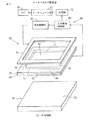
図面を参照すると、図1及び図2は、本発明の一実施形態による複合型表示装置10の構成を、それぞれ模式図的に示す断面図及び斜視図である。
Embodiments of the present invention will be described below in detail with reference to the accompanying drawings. Corresponding components are denoted by common reference symbols throughout the drawings.
Referring to the drawings, FIGS. 1 and 2 are a cross-sectional view and a perspective view, respectively, schematically showing the configuration of a
複合型表示装置10は、観察面12及び観察面12の反対側の背面14を有する平板状のEL表示部16と、EL表示部16の背面14に沿って配置される平板状の押下入力部18とを備える。EL表示部16は、一方の表面20aが観察面12を構成する光透過性及び可撓性を有する第1基板20と、観察面12とは反対側の第1基板20の裏面20bに薄膜状に形成される光透過性の陽極層22と、第1基板20から見て陽極層22の上に薄膜状に積層形成される発光機能層24と、第1基板20から見て発光機能層24の上に薄膜状に積層形成され、発光機能層24とは反対側の面26aが背面14を構成する陰極層26とを備える。
The
第1基板20は、PET(ポリエチレンテレフタレート)、PC(ポリカーボネート)等の樹脂材料から作製される。陽極層22は、ITO(酸化インジウム錫)等の導電性皮膜から形成される。発光機能層24は、陽極層24に隣接する正孔輸送層28と、陰極層26に隣接する電子輸送性の発光層30とを含んで構成され、正孔輸送層28としてはNPB(N,N-di(naphthalene-1-yl)-N,N-diphenyl-benzidene)等が、また発光層30としてはAlq3(アルミニウムキノリノール錯体)等が使用される。陰極層26は、Mg(マグネシウム)合金等の導電性皮膜から形成される。
The
陽極層24、正孔輸送層28、発光層30及び陰極層26は、第1基板20の裏面20bに対し順次、例えば真空蒸着法等の成膜技術によって積層形成される。陽極層24と陰極層26との間に直流電圧を印加すると、陽極層24から注入された正孔が正孔輸送層28を経て発光層30に到達する一方、陰極層26から注入された電子が発光層30に達し、それら正孔と電子とが発光層30で再結合することにより所定波長の光が発光層30に生じる。なお、本発明は、EL表示部16の構成を限定するものでなく、EL表示装置として従来知られている種々の構成をEL表示部に採用できる。
The
押下入力部18は、一般的なタッチパネルに類似した構成を有するものであり、第2基板32と、第2基板32の一表面32aに形成される下部導電膜34と、下部導電膜34に対し導通接触可能に対向かつ離間して配置される上部導電膜36とを備える。下部導電膜34の表面には、電気絶縁性の多数のドットスペーサ38が分散配置される。また下部導電膜34と上部導電膜36とは、両導電膜34、36の外周縁に沿って帯状に延設される電気絶縁性の接着剤層40によって相互に固定される。接着剤層40は、両導電膜34、36の間に予め定めた寸法の隙間42を確保する。またドットスペーサ38は、後述するように、上部導電膜36側の構成要素群の自重による変形を抑制して隙間42を維持する一方で、上部導電膜36側の構成要素群が押圧力下で変形したときには押圧位置における両導電膜34、36の短絡を許容する。
The
第2基板32は、ガラスや樹脂材料(PET等)から作製される。下部導電膜34及び上部導電膜36は、チタン等の比較的高強度の導電性皮膜から形成される。下部導電膜34は、第2基板32の表面32aに対し、スパッタリング等の成膜技術によって形成される。多数のドットスペーサ38は、例えば紫外線硬化樹脂材料からフォトレジスト法により、下部導電膜34上に所定パターンで形成される。また図示しないが、下部導電膜34及び上部導電膜36上には、それら導電膜34、36の互いに90度異なる対向辺に沿って配置される電極対と、導電膜34、36から絶縁してそれぞれの電極対に接続される配線ストリップとが、例えばスクリーン印刷法によりパターン形成される。
The
複合型表示装置10では、その特徴的構成として、EL表示部16の陰極層26と押下入力部18の上部導電膜36との間に、陰極層26の面26aすなわち背面14に成膜技術により被着形成される絶縁皮膜44が介在する。絶縁皮膜44は、例えばSiO2(二酸化ケイ素)からなり、陰極層26の背面14に対しスパッタリング等の成膜技術によって形成される。さらに、押下入力部18の上部導電膜36が、絶縁皮膜44に対しスパッタリング等の成膜技術により被着形成される。絶縁皮膜44は、陰極層26と上部導電膜36との間を確実に絶縁できる厚み及び材質を有する。
In the
複合型表示装置10を作製する際には、EL表示部16の第1基板20の裏面20bに対し、陽極層24、正孔輸送層28、発光層30、陰極層26、絶縁皮膜44及び上部導電膜36をこの順序で、いずれも成膜技術によって積層形成する。この状態で、上部導電膜36の表面に、電極対及び配線ストリップをパターン形成する。他方、押下入力部18の第2基板32の表面32aに、下部導電膜34を成膜し、下部導電膜34の表面に、多数のドットスペーサ38を設けるとともに電極対及び配線ストリップをパターン形成する。そして、これら上部導電膜36側の構成要素群と下部導電膜34側の構成要素群とを、両導電膜34、36を接着剤層40により相互に固着することにより、互いに固定的に連結し、それにより複合型表示装置10が完成する。
When the
上記構成を有する複合型表示装置10は、柔軟な薄板状構造を有するEL表示部16の背面14に沿って、二次元座標データ入力用の押下入力部18を設置したものであるから、表示装置の観察面側にタッチパネルを設置した従来の複合型表示装置に比べて、タッチパネルを透視することによる観察面の視認性低下の問題が解決される。また、押下入力部18に透視機能が要求されないので、押下入力部18の検出要素である下部及び上部導電膜34、36に、ITO等の透明導電膜に比べて機械的強度に優れた不透明な導電性皮膜を使用することができ、それにより押下入力部18の耐久性を向上させることができる。
Since the
さらに複合型表示装置10によれば、EL表示部16と押下入力部18とが、両者間に樹脂フィルム等の支持体を介在させること無く、EL表示部16の陰極層26に直接に成膜される絶縁皮膜44を介して相互に連結されるから、例えば既述の特許文献1に記載されるような、EL表示パネルの背面側支持体とタッチパネルの上側絶縁基板とが接着層を介して相互固着される従来構造における、背面側支持体と上側絶縁基板との膨張率の差に起因した接着層の剥離、EL表示パネルの歪み、タッチパネルの検出不良等の問題が確実に解決される。しかも、絶縁皮膜44は、EL表示部16と押下入力部18とを相互に絶縁するための必須構成要素であるとともに、一対の基板20、32の間で成膜技術によって順次形成される積層皮膜構造の一要素であるから、それぞれに独立した装置構成を有するEL表示パネルとタッチパネルとを互いに密着させる従来構造に比べ、EL表示パネルの背面側支持体とタッチパネルの上側絶縁基板との双方を省略でき、その結果、複合型表示装置10の全体の厚みを可及的に削減できる。したがって複合型表示装置10によれば、EL表示部16が本質的に奏する薄型化の効果を一層促進することができる。
Furthermore, according to the
図3及び図4は、表示装置の観察面側に設置される本発明の他の実施形態によるタッチパネル50を示す。タッチパネル50は、透明な絶縁基板52及び絶縁基板52の一表面52aに設けられる透明な導電膜54を有する第1検出部材56と、透明な絶縁基板58及び絶縁基板58の一表面58aに設けられる透明な導電膜60を有する第2検出部材62とを備える。それら第1及び第2検出部材56、62は、各々の導電膜54、60同士を隙間64を介し対向させた状態で、両導電膜54、60の周縁に沿って枠状に延設される接着剤層66を介して互いに固定される。
3 and 4 show a
第1検出部材56は、オペレータによって押圧操作される上側検出部材であり、その絶縁基板52は、PET、PC等の可撓性に富む樹脂フィルムから形成される。これに対し第2検出部材62は、LCD、PDP、CRT等の表示装置68の観察面70に隣接配置される下側検出部材であり、その絶縁基板58は、ガラス板、プラスチック板、樹脂フィルム等から形成される。また、各検出部材56、62の導電膜54、60は、ITO等の導電性皮膜からなり、例えば真空蒸着法によって各絶縁基板52、58の表面52a、58aに被着形成される。
The
第2検出部材62の導電膜60上には、電気絶縁性の多数のドットスペーサ72が分散配置される。それらドットスペーサ72は、第1検出部材56の自重による変形を抑制して隙間64を維持する一方で、第1検出部材56が押圧力下で変形したときには押圧位置における両導電膜54、60の短絡を許容する。多数のドットスペーサ72は、例えば紫外線硬化樹脂材料からフォトレジスト法により、導電膜60上に所定パターンで形成される。さらに、第1及び第2検出部材56、62の各々の導電膜54、60上には、それら導電膜54、60のそれぞれの対向辺に沿って互いに90度異なる位置に配置される各一対の電極74、76と、導電膜54、60から絶縁してそれら電極対74、76に接続される第1及び第2配線ストリップ(図示せず)とが、例えばスクリーン印刷法によりパターン形成される。
On the
タッチパネル50は、第1及び第2検出部材56、62の外周領域に設置されるシート状のEL素子78を備える。EL素子78は、タッチパネル50の接着剤層66に対応する枠状輪郭を有し、タッチパネル50の非検出機能領域(平面視で接着剤層66に重畳する領域)80に沿って、第1検出部材56の絶縁基板52の外面52bに例えば接着剤層(図示せず)を介して固定的に載置される。EL素子78は、タッチパネル50を併設する表示装置68の動作中に発光して、表示装置68の観察面70の主表示領域に重畳するタッチパネル50の検出機能領域(平面視で接着剤層66の内側の領域)82を照射したり、タッチパネル50の入力の実行をオペレータに認知させたりするように作用する。
The
上記構成を有するタッチパネル50では、例えば、表示装置68を起動すると同時にEL素子78に電圧を印加してEL素子78を継続的に発光させるように構成すれば、第1及び第2検出部材56、62の外周領域に設置されるシート状のEL素子78が、表示装置68の観察面70の主表示領域に重畳する検出機能領域82を照射するフロントライトとして機能する。このようなフロントライト構造は、場所を取らない小型軽量のものであるから、タッチパネル50及び表示装置68を含む複合システム全体の寸法及び重量の増加を可及的に抑制しつつ、観察面70の視認性を向上させることができる。或いはタッチパネル50を、その入力操作の都度、EL素子78に電圧を印加してEL素子78を断続的に発光させるように構成すれば、シート状のEL素子78が、表示装置68の画面表示以外にオペレータに入力の実行を即座に認知させる手段として機能する。このような入力認知手段によれば、複合システム全体の寸法及び重量の増加を可及的に抑制しつつ、タッチパネル50の操作確度を向上させることができる。
In the
EL素子78を、検出機能領域82を照射するフロントライトとして使用する場合は、EL素子78に隣接して導光部材84を設置することが有利である。導光部材84は、EL素子78に合致する輪郭を有して、絶縁基板52とは反対側でEL素子78の表面78aに固定的に載置され、EL素子78が発する光を検出機能領域82に導くように作用する。それにより、少ない電力でもEL素子78が発する光を効率的に使用して、観察面70の視認性を著しく向上させることができる。導光部材84の構成は、導光板として公知のプリズム状の構成を採用できる。
When the
EL素子78を、タッチパネル50の入力の実行をオペレータに認知させる手段として使用する場合は、第1及び第2検出部材56、62からの入力検出信号に応答してEL素子78を発光させる制御回路86を備えることが有利である。制御回路86は、第1及び第2検出部材56、62における入力情報を検出する入力情報検出部88と、入力情報検出部88で検出された入力情報に基づき、EL素子78へ印加する電圧を調整してEL素子78の発光を制御する発光制御部90とを備える。発光制御部90は、タッチパネル50が正確に入力操作されたとき(すなわち第1及び第2検出部材56、62が相互に導通接触したとき)に、EL素子78を発光させるように構成できる。なお、入力情報検出部88は、検出した入力情報を二次元座標データとして処理するタッチパネル50の処理部(CPU、メモリ等を含む)92に接続され、処理部92がインタフェース部94を介して、パーソナルコンピュータ等のデータ処理装置96に接続される。
When the
上記構成によれば、タッチパネル50の入力操作時に、正確な入力を行う都度、EL素子78を発光させることにより、オペレータに入力の実行を即座に認知させることができる。したがって、EL素子78及びその制御回路(実質的には発光制御部90)を追加するだけの極めて簡易な構造により、タッチパネル50の操作確度を著しく向上させることができる。
According to the above configuration, whenever an accurate input is performed on the
なおタッチパネル50では、フロントライト及び入力認知手段のいずれか一方の機能を有する1つのEL素子78を装備することもできるし、それら機能を分掌する2つ以上のEL素子78を装備することもできる。1つの機能を有するEL素子78は、図4及び図5(a)に示すように非検出機能領域80の全体に延設される枠状輪郭を有することもできるし、或いは図5(b)に示すように非検出機能領域80の所望箇所に配置される帯状輪郭を有することもできる。後者の場合、同一機能の複数個の帯状のEL素子78を使用することもできる。また、機能を分掌する2つ以上のEL素子78は、例えば図5(c)に示すように、フロントライト機能を有する平面視コ字状のEL素子781と、入力認知機能を有する平面視矩形状のEL素子782を組み合わせて使用することもできる。
Note that the
図1に示す複合型表示装置10を、以下の構成で作製した。
まず、表面20a(観察面12)にハードコート処理を施したPETフィルムからなる第1基板20の裏面20bに、スパッタリングにより100nm厚のITO製の陽極層22を成膜した。次に、陽極層22の露出面に、抵抗加熱式真空蒸着により50nm厚のNPB製の正孔輸送層28を成膜した。次に、正孔輸送層28の露出面に、抵抗加熱式真空蒸着により50nm厚のAlq3製の電子輸送性発光層30を成膜した。次に、発光層30の露出面に、抵抗加熱式真空蒸着(二元同時蒸着)により150nm厚のMg−Ag(マグネシウム銀合金)製の陰極層26を成膜した。次に、陰極層26の面26a(背面14)に、スパッタリングにより500nm厚のSiO2製の絶縁皮膜44を成膜した。次に、絶縁皮膜44の露出面に、スパッタリングにより100nm厚のTi(チタン)製の上部導電膜36を成膜した。上部導電膜36の露出面には、スクリーン印刷により銀ペーストからなる電極対及び配線ストリップを形成した。
A
First, an
他方、ソーダライムガラスからなる第2基板32の表面32aに、スパッタリングにより100nm厚のTi(チタン)製の下部導電膜34を成膜した。下部導電膜34の露出面には、スクリーン印刷により銀ペーストからなる電極対及び配線ストリップを形成するとともに、フォトレジスト法により紫外線硬化樹脂材料からなる複数のドットスペーサ38を形成した。最後に、上部導電膜36と下部導電膜34とを接着剤層40により相互に固着することにより、第1基板20に支持される上部導電膜36側の構成要素群と第2基板32に支持される下部導電膜34側の構成要素群とを互いに固定的に連結し、それにより複合型表示装置10を作製した。完成した複合型表示装置10は、層間剥離、EL表示パネルの歪み、タッチパネルの検出不良等を生じることなく安定して操作できるものであって、全体の厚みを削減した薄型表示装置が実現された。
On the other hand, a lower
本発明に係る複合型表示装置は、例えばパーソナルコンピュータ、携帯情報端末(PDA)、現金自動預払機(ATM)等の、表示装置を備えたデータ処理装置において使用でき、特に、表示装置自体の薄型化が要求される用途で有効に使用される。また、本発明に係るタッチパネルは、特に暗所での使用が予測されるタッチパネル付き表示装置において有効に使用できる。 The composite display device according to the present invention can be used in a data processing device equipped with a display device such as a personal computer, a personal digital assistant (PDA), an automatic teller machine (ATM), and the display device itself is particularly thin. It is effectively used in applications that require the In addition, the touch panel according to the present invention can be used effectively in a display device with a touch panel that is predicted to be used particularly in a dark place.
10…複合型表示装置
12…観察面
14…背面
16…EL表示部
18…押下入力部
20…第1基板
22…陽極層
24…発光機能層
26…陰極層
28…正孔輸送層
30…発光層
32…第2基板
34…下部導電膜
36…上部導電膜
40、66…接着剤層
44…絶縁皮膜
50…タッチパネル
52、58…絶縁基板
54、60…導電膜
56…第1検出部材
62…第2検出部材
78、781、782…EL素子
80…非検出機能領域
82…検出機能領域
84…導光部材
86…制御回路
DESCRIPTION OF
Claims (5)
前記EL表示部は、前記観察面を有するとともに光透過性及び可撓性を有する第1基板と、該観察面の反対側の該第1基板の裏面に形成される光透過性の陽極層と、該陽極層に積層される発光機能層と、該発光機能層に積層され、前記背面を有する陰極層とを備え、
前記押下入力部は、第2基板と、該第2基板の一表面に形成される下部導電膜と、該下部導電膜に対し導通接触可能に対向かつ離間して配置される上部導電膜とを備え、
前記EL表示部の前記陰極層と前記押下入力部の前記上部導電膜との間に、該陰極層の前記背面に成膜技術により被着形成される絶縁皮膜が介在すること、
を特徴とする複合型表示装置。 In a composite display device comprising a flat EL display unit having an observation surface and a back surface opposite to the observation surface, and a flat press input unit arranged along the back surface of the EL display unit,
The EL display unit includes a first substrate having the observation surface and light transmission and flexibility, and a light transmission anode layer formed on the back surface of the first substrate on the opposite side of the observation surface. A light emitting functional layer laminated on the anode layer, and a cathode layer laminated on the light emitting functional layer and having the back surface,
The pressing input unit includes a second substrate, a lower conductive film formed on one surface of the second substrate, and an upper conductive film disposed opposite to and spaced from the lower conductive film so as to be in conductive contact. Prepared,
Between the cathode layer of the EL display unit and the upper conductive film of the pressing input unit, an insulating film deposited on the back surface of the cathode layer by a film forming technique is interposed,
A composite display device characterized by the above.
前記一対の検出部材の外周領域に設置され、表示装置の動作中に発光するシート状のEL素子を具備することを特徴とするタッチパネル。 A pair of detection members each having a transparent insulating substrate and a transparent conductive film provided on one surface of the insulating substrate, the detection members being opposed to each other in a relative arrangement so that the conductive films can be in conductive contact with each other; In the combined state, in the touch panel that is mounted and used on the observation surface of the display device,
A touch panel comprising a sheet-like EL element that is installed in an outer peripheral region of the pair of detection members and emits light during operation of the display device.
Priority Applications (1)
| Application Number | Priority Date | Filing Date | Title |
|---|---|---|---|
| JP2003418151A JP2005182152A (en) | 2003-12-16 | 2003-12-16 | Composite display device and touch panel juxtaposed to the display device |
Applications Claiming Priority (1)
| Application Number | Priority Date | Filing Date | Title |
|---|---|---|---|
| JP2003418151A JP2005182152A (en) | 2003-12-16 | 2003-12-16 | Composite display device and touch panel juxtaposed to the display device |
Publications (1)
| Publication Number | Publication Date |
|---|---|
| JP2005182152A true JP2005182152A (en) | 2005-07-07 |
Family
ID=34780441
Family Applications (1)
| Application Number | Title | Priority Date | Filing Date |
|---|---|---|---|
| JP2003418151A Pending JP2005182152A (en) | 2003-12-16 | 2003-12-16 | Composite display device and touch panel juxtaposed to the display device |
Country Status (1)
| Country | Link |
|---|---|
| JP (1) | JP2005182152A (en) |
Cited By (5)
| Publication number | Priority date | Publication date | Assignee | Title |
|---|---|---|---|---|
| WO2008032476A1 (en) * | 2006-09-11 | 2008-03-20 | Sharp Kabushiki Kaisha | Display device provided with touch panel |
| JP2009086752A (en) * | 2007-09-27 | 2009-04-23 | Seiko Precision Inc | Illumination touch panel and manufacturing method of the same |
| KR101071672B1 (en) * | 2009-06-23 | 2011-10-11 | 한국표준과학연구원 | Brightness controllable electro luminescence device with tactile sensor sensing intensity of force or intensity of pressure, flat panel display having the same, mobile terminal keypad having the same |
| CN106383610A (en) * | 2016-09-21 | 2017-02-08 | 京东方科技集团股份有限公司 | Pressing feedback apparatus, display apparatus and control method of display apparatus |
| WO2020134083A1 (en) * | 2018-12-28 | 2020-07-02 | 云谷(固安)科技有限公司 | Display panel and manufacturing method thereof, and display device |
-
2003
- 2003-12-16 JP JP2003418151A patent/JP2005182152A/en active Pending
Cited By (8)
| Publication number | Priority date | Publication date | Assignee | Title |
|---|---|---|---|---|
| WO2008032476A1 (en) * | 2006-09-11 | 2008-03-20 | Sharp Kabushiki Kaisha | Display device provided with touch panel |
| US8350817B2 (en) | 2006-09-11 | 2013-01-08 | Sharp Kabushiki Kaisha | Display device provided with touch panel |
| JP2009086752A (en) * | 2007-09-27 | 2009-04-23 | Seiko Precision Inc | Illumination touch panel and manufacturing method of the same |
| KR101071672B1 (en) * | 2009-06-23 | 2011-10-11 | 한국표준과학연구원 | Brightness controllable electro luminescence device with tactile sensor sensing intensity of force or intensity of pressure, flat panel display having the same, mobile terminal keypad having the same |
| CN106383610A (en) * | 2016-09-21 | 2017-02-08 | 京东方科技集团股份有限公司 | Pressing feedback apparatus, display apparatus and control method of display apparatus |
| CN106383610B (en) * | 2016-09-21 | 2019-07-05 | 京东方科技集团股份有限公司 | A kind of pressing feedback device, display device and its control method |
| WO2020134083A1 (en) * | 2018-12-28 | 2020-07-02 | 云谷(固安)科技有限公司 | Display panel and manufacturing method thereof, and display device |
| US11910691B2 (en) | 2018-12-28 | 2024-02-20 | Yungu (Gu'an) Technology Co., Ltd. | Display panel, manufacturing method thereof, and display device |
Similar Documents
| Publication | Publication Date | Title |
|---|---|---|
| US9772727B2 (en) | Touch panel | |
| US8581865B2 (en) | Touch panel, display device with the same, and method for manufacturing the display device | |
| US10649589B2 (en) | Touch apparatus, electronic device and preparing method | |
| US20130044384A1 (en) | Color filter substrate embedded with touch sensor and method for manufacturing the same | |
| KR101521681B1 (en) | Touch Panel | |
| US20100127992A1 (en) | Multi-touch active display keyboard | |
| US20090085890A1 (en) | Touch Panel and Touch Panel Manufacturing Method | |
| JP2019012554A (en) | Touch input device | |
| CN101387772B (en) | Touch control display panel, display and mobile phone | |
| CN108885506B (en) | Pressure sensor, touch input device including the same, and pressure detection method using the same | |
| US9446571B2 (en) | Touch panel and method of manufacturing touch panel | |
| KR20130110539A (en) | Display device and manufacturing method of the same | |
| KR20140038822A (en) | A raw glass plate for manufacturing a touch panel and method for manufacturing touch panel using the same | |
| JP2011159094A (en) | Method for manufacturing electric solid state device | |
| WO2011105202A1 (en) | Input device, display device, and portable terminal | |
| US8421343B2 (en) | Organic light emitting display device and manufacturing method therefor | |
| US20110279394A1 (en) | Touch screen panel structure of mobile device | |
| JP2005182152A (en) | Composite display device and touch panel juxtaposed to the display device | |
| KR20140076174A (en) | Touch Panel | |
| US7679608B2 (en) | Touch panel | |
| US20130279152A1 (en) | Touch panel | |
| CN116322180A (en) | Display panel, display device and preparation method of display panel | |
| US11520183B2 (en) | Touch front light module and touch display device | |
| KR20160005596A (en) | Touch window | |
| CN110543260B (en) | Touch screen, display panel and automobile diagnosis equipment |