JP2005178451A - Method for manufacturing air bag door skin - Google Patents
Method for manufacturing air bag door skin Download PDFInfo
- Publication number
- JP2005178451A JP2005178451A JP2003419015A JP2003419015A JP2005178451A JP 2005178451 A JP2005178451 A JP 2005178451A JP 2003419015 A JP2003419015 A JP 2003419015A JP 2003419015 A JP2003419015 A JP 2003419015A JP 2005178451 A JP2005178451 A JP 2005178451A
- Authority
- JP
- Japan
- Prior art keywords
- skin
- airbag
- groove
- airbag door
- manufacturing
- Prior art date
- Legal status (The legal status is an assumption and is not a legal conclusion. Google has not performed a legal analysis and makes no representation as to the accuracy of the status listed.)
- Pending
Links
- 238000004519 manufacturing process Methods 0.000 title claims abstract description 23
- 238000000034 method Methods 0.000 title claims abstract description 14
- 238000003801 milling Methods 0.000 claims abstract description 36
- 238000005520 cutting process Methods 0.000 claims abstract description 16
- 210000003491 skin Anatomy 0.000 description 56
- 239000000463 material Substances 0.000 description 9
- 230000003014 reinforcing effect Effects 0.000 description 6
- 210000002615 epidermis Anatomy 0.000 description 3
- 238000010438 heat treatment Methods 0.000 description 2
- 238000010008 shearing Methods 0.000 description 2
- 238000004891 communication Methods 0.000 description 1
- 238000007796 conventional method Methods 0.000 description 1
- 230000000694 effects Effects 0.000 description 1
- 238000005187 foaming Methods 0.000 description 1
- 238000001746 injection moulding Methods 0.000 description 1
- 238000003754 machining Methods 0.000 description 1
- 239000011347 resin Substances 0.000 description 1
- 229920005989 resin Polymers 0.000 description 1
- 239000000758 substrate Substances 0.000 description 1
- 238000003466 welding Methods 0.000 description 1
Images


Abstract
Description
本発明は、車両用エアバッグドアの破断予定部に対応する表皮裏面に切削工具により、溝部を加工するエアバッグドア表皮の製造方法に関するものである。 The present invention relates to a method for manufacturing an airbag door skin, in which a groove portion is processed with a cutting tool on the back surface of the skin corresponding to a planned fracture portion of a vehicle airbag door.
従来より、車両に、その衝突時の衝撃から乗員を保護するためのエアバッグ装置を装備することは一般に知られている。このエアバッグ装置をインストルメントパネルの裏側に装着する場合、その基材にエアバッグの膨張圧力で展開するエアバッグドアが設けられる。例えば基材に、他の部分よりも脆弱でエアバッグの膨張圧力で破断する破断予定部と、エアバッグドアの開動作の回動中心となるヒンジ部とを枠状に形成して、これら破断予定部及びヒンジ部により区画される矩形領域でエアバッグドアを構成するようにしている。上記破断予定部に対応するように、上記基材を覆う表皮にも機械的に弱い溝部が設けられる。この溝部は、表皮の表面の美観を損なわないようにするため、例えば、レーザーカッター、加熱刃等を用いて表皮の裏面に表面側に表皮を残存させて設けられる。 Conventionally, it is generally known to equip a vehicle with an airbag device for protecting an occupant from an impact at the time of the collision. When the airbag device is mounted on the back side of the instrument panel, an airbag door that is deployed by the inflation pressure of the airbag is provided on the base material. For example, the base material is formed in a frame shape with a planned breakage portion that is weaker than other portions and breaks due to the inflation pressure of the airbag, and a hinge portion that serves as a pivot center for the opening operation of the airbag door. The airbag door is configured by a rectangular region defined by the planned portion and the hinge portion. A groove that is mechanically weak is also provided in the skin covering the base material so as to correspond to the planned fracture portion. In order not to impair the appearance of the surface of the skin, the groove is provided, for example, by using a laser cutter, a heating blade or the like so that the skin is left on the surface side on the back surface of the skin.
しかし、レーザーカッターで溝部を形成する製造方法では、設備コストの高いレーザー加工機を用いなければならず、そのランニングコストも高価である。 However, in the manufacturing method in which the groove is formed with a laser cutter, a laser processing machine with a high equipment cost must be used, and the running cost is also expensive.
また、加熱刃を用いる製造方法では、圧接時に表面側に圧接跡が残ったり、刃先の熱容量が大きすぎて溝部の周辺にまで熱影響が及んで変形したりするので、表皮の見映えが悪くなる。 In addition, in the manufacturing method using a heating blade, the pressure contact mark remains on the surface side during pressure welding, or the heat capacity of the blade tip is too large and deforms due to heat influence around the groove, so the appearance of the skin is poor. Become.
そこで、ロボットのアームにミシン目カッター、超音波裁断機等を取り付けてエアバッグ表皮に溝部を形成するものが知られている(例えば、特許文献1参照)。
しかしながら、上記従来のエアバッグドア表皮の製造方法によると、ミシン目カッターや超音波裁断機等により形成された溝部は、平坦な底部を有していて表皮の表面側に向かって尖っていないため、該底部で応力集中が起こり難い。このため、表皮が確実に定位置で破断せずにエアバッグの膨出を阻害する場合がある。 However, according to the above-described conventional method for manufacturing an airbag door skin, the groove formed by a perforation cutter or an ultrasonic cutter has a flat bottom and is not pointed toward the surface side of the skin. , Stress concentration hardly occurs at the bottom. For this reason, there is a case where the epidermis does not break at a fixed position and hinders inflation of the airbag.
本発明は、かかる点に鑑みてなされたものであり、その目的とするところは、エアバッグドア表皮に溝部を加工するための切削工具を適切に選択することにより、表面側に溝部の形状が現れないで見映えがよく、かつエアバッグの膨出時にエアバッグドアの破断予定部で確実に破断する車両用エアバッグドア表皮を簡単な装置で容易に製造できるようにすることにある。 The present invention has been made in view of the above points, and the object of the present invention is to appropriately select a cutting tool for processing the groove portion on the airbag door skin so that the shape of the groove portion on the surface side is improved. An object of the present invention is to make it possible to easily manufacture a vehicular airbag door skin that does not appear and has a good appearance and breaks reliably at a scheduled breakage portion of the airbag door when the airbag is inflated with a simple device.
上記の目的を達成するために、この発明では、フライスにより表皮の溝部を加工するようにした。 In order to achieve the above object, in the present invention, the groove portion of the epidermis is processed by a milling cutter.
具体的には、請求項1の発明では、車両用エアバッグドアの破断予定部に対応する表皮裏面に切削工具により、表面側に表皮を残存させて溝部を加工するエアバッグドア表皮の製造方法を対象とする。
Specifically, in the invention of
上記切削工具は、切れ刃がそれぞれ形成された第1面と第2面とが主軸に垂直な方向から見て30°以上でかつ80°以下の刃角で交差するように形成されたフライスよりなり、上記フライスを回転させ、上記第1面及び第2面の切れ刃により上記表皮裏面に略V字状の溝部を加工する。 The cutting tool includes a milling cutter formed such that the first surface and the second surface on which cutting edges are formed intersect each other at a blade angle of 30 ° or more and 80 ° or less when viewed from a direction perpendicular to the main axis. Then, the milling cutter is rotated, and a substantially V-shaped groove portion is processed on the back surface of the skin by the cutting edges of the first surface and the second surface.
請求項2の発明では、上記フライスの第1面は上記主軸に直交しており、該主軸は、上記表皮裏面に対し、0°以上でかつ上記第1面と第2面との間の上記刃角以下になるように、傾斜角が設定されている。
In the invention of
請求項3の発明では、上記フライスの第1面と第2面との間の刃角の二等分線が上記主軸に直交しており、該主軸は、上記表皮裏面に対し、0°以上でかつ上記刃角の1/2以下になるように、傾斜角が設定されている。
In the invention of
上記請求項1の発明のエアバッグドア表皮の製造方法では、主軸に垂直な方向から見て30°以上でかつ80°以下の刃角で交差する第1面と第2面の切れ刃を有するフライスにより、表皮裏面に略V字状の溝部を加工するようにした。
In the manufacturing method of the airbag door skin of the said invention of
このとき、上記刃角を30°よりも小さくすると、V字状溝部の傾斜角が大きくなってその幅が狭くなり溝部の加工が困難である一方、80°よりも大きくすると、V字状溝部における傾斜角が小さくなってその幅方向の肉厚が全体的に軽くなり、該溝部の底部(V字の最深底部)で応力集中が起こり難く、上記最深底部からの剪断力が該底部側に伝わり難くなり、表皮の破断線が一定しない。また、刃角を30°以上でかつ80°以下に限定した上でフライスの第1面と第2面とに形成した2つの切れ刃の交差する先端で溝部をV字状に形成しているので、尖った底部に応力集中が起きて該底部で表皮を破断させてエアバッグドアを確実に展開させることができ、エアバッグの膨出を妨げることはない。また、フライスの形状や主軸の傾斜角度を調整することで、溝部の形状の変更が容易である。したがって、見映えがよく、かつエアバッグの膨出時に溝部の尖った底部で確実に破断する車両用エアバッグドア表皮を簡単な装置で容易に製造することができる。 At this time, if the blade angle is smaller than 30 °, the inclination angle of the V-shaped groove portion is increased and the width thereof is narrowed, making it difficult to process the groove portion. On the other hand, if it is larger than 80 °, the V-shaped groove portion is The inclination angle becomes smaller and the thickness in the width direction becomes lighter as a whole. Stress concentration hardly occurs at the bottom of the groove (the deepest bottom of the V-shape), and the shearing force from the deepest bottom is applied to the bottom. It becomes difficult to transmit, and the rupture line of the epidermis is not constant. Moreover, after limiting the blade angle to 30 ° or more and 80 ° or less, a groove portion is formed in a V shape at the tip of two cutting blades formed on the first surface and the second surface of the milling cutter. Therefore, stress concentration occurs at the pointed bottom, the skin can be broken at the bottom, and the airbag door can be reliably deployed, and the expansion of the airbag is not hindered. Further, the shape of the groove can be easily changed by adjusting the shape of the milling cutter and the inclination angle of the main shaft. Therefore, it is possible to easily manufacture a vehicle airbag door skin that has good appearance and that is surely broken at the bottom of the groove when the airbag is inflated with a simple device.
請求項2の発明では、主軸に直交する第1面を備えたフライスを用い、それを回転させる主軸を表皮裏面に対し、0°以上でかつの第1面と第2面との間の刃角以下になるように傾斜させた。 According to a second aspect of the present invention, a milling machine having a first surface orthogonal to the main axis is used, and the blade between the first surface and the second surface is rotated at 0 ° or more with respect to the back surface of the main shaft to rotate the main shaft. It was made to incline so that it might become below a corner.
このような、いわゆる片角フライスでは、主軸の傾斜角を、0°よりも小さくすると表皮と主軸とが干渉して加工ができない一方、刃角よりも大きくすると、溝部の底部がアンダー形状となり、溝部の加工が困難となる。したがって、このように主軸の表皮裏面に対する傾斜角を限定することで、溝部の加工を容易に行うことができる。 In such a so-called single-angle milling machine, if the inclination angle of the main shaft is smaller than 0 °, the skin and the main shaft interfere with each other and cannot be machined. It becomes difficult to process the groove. Therefore, the groove portion can be easily processed by limiting the inclination angle of the main shaft with respect to the back surface of the skin in this way.
請求項3の発明では、第1面と第2面との間の刃角の二等分線を主軸に直交させたフライスを用い、それを回転させる主軸を、表皮裏面に対して0°以上でかつ上記刃角の1/2以下になるように傾斜させた。
In the invention of
このような、いわゆる等角フライスにおいても、主軸の傾斜角を、0°よりも小さくすると表皮と主軸とが干渉して加工ができない一方、刃角の1/2よりも大きくすると、溝部の底部がアンダー形状となり、溝部の加工が困難となる。したがって、このように主軸の表皮裏面に対する傾斜角を限定することで、溝部の加工を容易に行うことができる。 Even in such a so-called equiangular milling machine, if the inclination angle of the main shaft is smaller than 0 °, the skin and the main shaft interfere with each other, and machining cannot be performed. Becomes under-shaped, making it difficult to process the groove. Therefore, the groove portion can be easily processed by limiting the inclination angle of the main shaft with respect to the back surface of the skin in this way.
以下、本発明の実施形態を図面に基づいて説明する。 Hereinafter, embodiments of the present invention will be described with reference to the drawings.
(実施形態1)
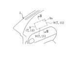
図1は、車両の助手席側車室内前部を示し、同図における左上側が車両の前側すなわちフロントガラス側で、右下側が後側すなわち助手席側となっている。車室内前部には、本発明の実施形態1に係る表皮を備えたインストルメントパネル1が配置されている。
(Embodiment 1)
FIG. 1 shows the front passenger compartment side of the vehicle. The upper left side in FIG. 1 is the front side of the vehicle, that is, the windshield side, and the lower right side is the rear side, that is, the passenger seat side. An
図2に示すように、上記インストルメントパネル1は、樹脂製の基材3と、この基材3の表面に一体に接合された表皮5とからなる。図3にも拡大詳示するように、上記基材3の裏面には、表面側に向けて凹陥する例えば断面V字状の破断溝7がインストルメントパネル1表面側から見て矩形の四辺のうち前側(図2で左側)を除く各辺をなすように形成されている(図1に破線で示す)。この破断溝7によって基材3の表面側に薄肉の破断予定部9が形成されている。この破断予定部9に対応する表皮5裏面に表面側に表皮5の一部を残存させて断面略V字状の溝部11が形成されている。
As shown in FIG. 2, the
そして、後述するエアバッグ装置31の作動による破断予定部9の破断により、上記四辺のうちの前側の一辺である前側部9a(図1に一点鎖線で示す)を中心に車室内側に展開する矩形状のエアバッグドア13が形成されている。このエアバッグドア13は、上記表皮5の溝部11がインストルメントパネル1の表面側から識別できない、いわゆるシームレスタイプに構成されている。
And by the fracture | rupture of the planned fracture |
上記インストルメントパネル1の裏面には、上記エアバッグドア13の裏面に一体的に溶着された矩形板状の補強プレート部15と、該補強プレート部15を隙間を有してエアバッグが膨出されるシューティング口17が形成されインストルメントパネル1の基材3の裏面に一体的に溶着された矩形枠状の枠部本体19と、この枠部本体19の裏面に一体に突設された矩形筒状の筒状部21と、上記前側部9aに対応する筒状部21の前側部21aの上端部に上記補強プレート部15の前端部を接続するヒンジ部23とが射出成形により一体成形された枠体24が取り付けられている。
On the back surface of the
上記筒状部21の内部に公知のエアバッグ装置31が配置収容されている。このエアバッグ装置31は、図外の車体部材に結合されたエアバッグケース33を備え、このエアバッグケース33内には、図示しないが、車両の衝突時に高圧ガスを噴出させるインフレータと、このインフレータからの高圧ガスが充填されて折畳み状態から膨張するエアバッグとが収容されている。なお、筒状部21の中間部には係合孔25が形成され、この係合孔25にはエアバッグケース33側面に突設した係合部35が挿入されており、エアバッグ装置31の作動時に上記係合孔25と係合部35とが係止することにより、筒状部21等がエアバッグと共に車室内に突出するのを防ぐようにしている。
A known
したがって、上記実施形態においては、車両の衝突によりエアバッグ装置31が作動してエアバッグがエアバッグケース33から膨出すると、このエアバッグの展開圧力を補強プレート部15と、該補強プレート部15が溶着一体化されているインストルメントパネル1のエアバッグドア13とが受けて、インストルメントパネル1の破断予定部9が破断すると共に、この破断予定部9上の表皮5も上記溝部11から破れる。そして、エアバッグドア13がヒンジ部23を中心に補強プレート部15と共に開いて、インストルメントパネル1のエアバッグドア13の跡に、破断予定部9及び前側部9aで区画されてシューティング口17に連通する開口が生じ、エアバッグがシューティング口17ないし上記インストルメントパネル1の開口を経て車室内に展開する。
Therefore, in the above embodiment, when the
−表皮の製造方法−
次に上記表皮5に溝部11を加工する本発明の実施形態1に係る表皮5の製造方法について説明する。
-Manufacturing method of epidermis-
Next, the manufacturing method of the
図4に示すように、まず、表皮5を図示しないフライス盤に載置する。フライス盤の主軸(フライス43を回転させる回転軸)41には、切れ刃がそれぞれ形成された第1面45と第2面47とが該主軸41に垂直な方向(すなわち、同図の手前側)から見た刃角αが60°で交差するように形成されたフライス43が取り付けられている。
As shown in FIG. 4, first, the
上記フライス43は、その第1面45が上記主軸41に直交した、いわゆる片角フライスである。上記主軸41は、上記表皮5裏面に対し、傾斜角βが30°になるように設定されている。
The
そして、主軸41によりフライス43を回転させながら破断予定部9に対応するように表皮5裏面上を移動させ、表面側(同図では下側)に表皮5を残存させて溝部11を加工する。上記のように刃角α、傾斜角βを設定することで底部が尖ったV字状断面の溝部11が形成される。
Then, while rotating the
また、図5に示すように、傾斜角βを60°とすると、同図の右側の側壁が垂直な溝部11が形成され、図6に示すように、傾斜角βを0°とすると、同図の左側の側壁が垂直な溝部11が形成される。
Further, as shown in FIG. 5, when the inclination angle β is 60 °, a
このように、主軸41の傾斜角βを変更することで、溝部11の形状を容易に変更できる。
In this way, the shape of the
なお、上記刃角αは30°以上かつ80°以下に(30°≦α≦80°)に設定することができる。上記刃角αを30°よりも小さくすると、V字状溝部11の傾斜角が大きくなってその幅が狭くなり溝部11の加工が困難である一方、80°よりも大きくすると、V字状溝部11における傾斜角が小さくなってその幅方向の肉厚が全体的に軽くなり、該溝部11の底部(V字の最深底部)で応力集中が起こり難く、上記最深底部からの剪断力が該底部側に伝わり難くなり、表皮5の破断線が一定しない。また、刃角αを30°以上でかつ80°以下に限定した上でフライス43の第1面45と第2面47とに形成した2つの切れ刃の交差する先端で溝部11をV字状に形成しているので、尖った底部に応力集中が起きて該底部で表皮を破断させてエアバッグドア13を確実に展開させることができ、エアバッグの膨出を妨げることはない。
The blade angle α can be set to 30 ° or more and 80 ° or less (30 ° ≦ α ≦ 80 °). When the blade angle α is smaller than 30 °, the inclination angle of the V-shaped
また、上記傾斜角βは0°以上でかつ刃角α以下(0≦β≦α)に設定することができる。主軸41の傾斜角βを0°の場合(図6参照)よりも小さくすると、主軸41と表皮5とが干渉して溝部11の加工が不可能となり、また、傾斜角βを刃角αの場合(図5参照)よりも大きくすると、溝部11の底部がアンダー形状となり、溝部11の加工が困難となる。
The inclination angle β can be set to 0 ° or more and a blade angle α or less (0 ≦ β ≦ α). If the inclination angle β of the
したがって、実施形態1に係るエアバッグドア表皮の製造方法によると、表面側に溝部11の形状が現れないで見映えがよく、エアバッグの膨出時に上記溝部11の尖った底部で確実に破断する車両用エアバッグドアの表皮5を簡単な装置で容易に製造することができる。
Therefore, according to the manufacturing method of the airbag door skin according to the first embodiment, the shape of the
(実施形態2)
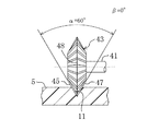
図7は本発明の実施形態2を示し、フライス43の形状が異なる点で上記実施形態1と異なる。なお、本実施形態では、図1〜図6と同じ部分については同じ符号を付してその詳細な説明は省略する。
(Embodiment 2)
FIG. 7 shows
図7に第1面45と第2面47との間の刃角αが60°で、該刃角αの二等分線48を主軸41に直交させたいわゆる等角フライス43を示す。同図では、主軸41を表皮5裏面に対し、傾斜角βが0°になるように傾斜させている。
FIG. 7 shows a so-called
この等角フライス43では、主軸41の表皮5裏面に対する傾斜角βが図7に示す0°から図8に示す30°すなわち上記刃角αの1/2以下(0≦β≦1/2α)に設定することができる。主軸41の傾斜角βを0°の場合(図7参照)よりも小さくすると、主軸41と表皮5とが干渉して溝部11の加工が不可能となり、また、傾斜角βを刃角αの1/2の場合(図8参照)よりも大きくすると、溝部11の底部がアンダー形状となり、溝部11の加工が困難となる。このように限定することで上記実施形態1と同じ作用効果が得られる。
In this
(その他の実施形態)
本発明は、上記各実施形態について、以下のような構成としてもよい。
(Other embodiments)
The present invention may be configured as follows for each of the above embodiments.
上記各実施形態では、インストルメントパネル1を基材3と表皮5で構成したが、これら基材3と表皮5との間に発泡層を設けてもよい。
In each said embodiment, although the
フライス43の形状を、上記実施形態1では片角フライスとし、上記実施形態2では等角フライスとしたが、これらのフライスの形状には限定されない。要は、フライス43は、切れ刃がそれぞれ形成された第1面と第2面とを有し、その刃角αが30°≦α≦80°となるものを選択すればよい。
Although the shape of the
上記各実施形態では、エアバッグドア13をインストルメントパネル1に設けたが、本発明はこれに限られるものではなく、インストルメントパネル1以外の例えば車両のステアリングホイール(ハンドル)等にエアバッグドアを設けてもよい。
In each of the above embodiments, the
以上説明したように、本発明は、車両用エアバッグドアの破断予定部に対応する表皮裏面に溝部を加工する表皮の製造方法について有用である。 As described above, the present invention is useful for a method for manufacturing a skin in which a groove is formed on the back surface of the skin corresponding to a planned fracture portion of a vehicle airbag door.
3 基材
5 表皮
7 破断溝
9 破断予定部
11 溝部
13 エアバッグドア
41 主軸
43 フライス
45 第1面
47 第2面
DESCRIPTION OF
Claims (3)
上記切削工具は、切れ刃がそれぞれ形成された第1面と第2面とが主軸に垂直な方向から見て30°以上でかつ80°以下の刃角で交差するように形成されたフライスよりなり、
上記フライスを回転させ、上記第1面及び第2面の切れ刃により上記表皮裏面に略V字状の溝部を加工することを特徴とするエアバッグドア表皮の製造方法。 A method for manufacturing an airbag door skin, in which a groove is formed by leaving a skin on the surface side by using a cutting tool on the back surface of the skin corresponding to a planned fracture portion of a vehicle airbag door,
The cutting tool includes a milling cutter formed such that the first surface and the second surface on which cutting edges are formed intersect each other at a blade angle of 30 ° or more and 80 ° or less when viewed from a direction perpendicular to the main axis. Become
A method of manufacturing an airbag door skin, wherein the milling machine is rotated, and a substantially V-shaped groove is formed on the back surface of the skin by the cutting edges of the first surface and the second surface.
上記フライスの第1面は上記主軸に直交しており、
上記主軸は、上記表皮裏面に対し、0°以上でかつ上記第1面と第2面との間の上記刃角以下になるように、傾斜角が設定されていることを特徴とするエアバッグドア表皮の製造方法。 In the manufacturing method of the airbag door skin of Claim 1,
The first surface of the milling cutter is orthogonal to the main axis;
The airbag is characterized in that an inclination angle is set so that the main shaft has an angle of 0 ° or more with respect to the back surface of the skin and not more than the blade angle between the first surface and the second surface. Manufacturing method of door skin.
上記フライスの第1面と第2面との間の刃角の二等分線が上記主軸に直交しており、
上記主軸は、上記表皮裏面に対し、0°以上でかつ上記刃角の1/2以下になるように、傾斜角が設定されていることを特徴とするエアバッグドア表皮の製造方法。
In the manufacturing method of the airbag door skin of Claim 1,
The bisector of the blade angle between the first surface and the second surface of the milling cutter is perpendicular to the main axis;
The manufacturing method of an airbag door skin, wherein the inclination angle is set so that the main shaft is 0 ° or more and 1/2 or less of the blade angle with respect to the back surface of the skin.
Priority Applications (1)
| Application Number | Priority Date | Filing Date | Title |
|---|---|---|---|
| JP2003419015A JP2005178451A (en) | 2003-12-17 | 2003-12-17 | Method for manufacturing air bag door skin |
Applications Claiming Priority (1)
| Application Number | Priority Date | Filing Date | Title |
|---|---|---|---|
| JP2003419015A JP2005178451A (en) | 2003-12-17 | 2003-12-17 | Method for manufacturing air bag door skin |
Publications (1)
| Publication Number | Publication Date |
|---|---|
| JP2005178451A true JP2005178451A (en) | 2005-07-07 |
Family
ID=34781032
Family Applications (1)
| Application Number | Title | Priority Date | Filing Date |
|---|---|---|---|
| JP2003419015A Pending JP2005178451A (en) | 2003-12-17 | 2003-12-17 | Method for manufacturing air bag door skin |
Country Status (1)
| Country | Link |
|---|---|
| JP (1) | JP2005178451A (en) |
Cited By (3)
| Publication number | Priority date | Publication date | Assignee | Title |
|---|---|---|---|---|
| KR100785195B1 (en) | 2006-01-25 | 2007-12-11 | 현대모비스 주식회사 | Passenger Air-Bag Module |
| US20110211927A1 (en) * | 2008-10-30 | 2011-09-01 | Faurecia Interieur Industrie | Process for manufacturing an automobile interior trim part with an airbag cover and to the associated machine |
| CN102922012A (en) * | 2012-10-17 | 2013-02-13 | 恒锋工具股份有限公司 | Wheel groove broach layered multi-tool tooth groove rough/finish-milling method |
-
2003
- 2003-12-17 JP JP2003419015A patent/JP2005178451A/en active Pending
Cited By (4)
| Publication number | Priority date | Publication date | Assignee | Title |
|---|---|---|---|---|
| KR100785195B1 (en) | 2006-01-25 | 2007-12-11 | 현대모비스 주식회사 | Passenger Air-Bag Module |
| US20110211927A1 (en) * | 2008-10-30 | 2011-09-01 | Faurecia Interieur Industrie | Process for manufacturing an automobile interior trim part with an airbag cover and to the associated machine |
| US9150183B2 (en) * | 2008-10-30 | 2015-10-06 | Faurecia Interieur Industrie | Process for manufacturing an automobile interior trim part with an airbag cover and to the associated machine |
| CN102922012A (en) * | 2012-10-17 | 2013-02-13 | 恒锋工具股份有限公司 | Wheel groove broach layered multi-tool tooth groove rough/finish-milling method |
Similar Documents
| Publication | Publication Date | Title |
|---|---|---|
| JP3470755B2 (en) | Automotive airbag cover with perforated break line | |
| JP4831999B2 (en) | VEHICLE AIRBACK DEVICE AND AIRBACK COVER | |
| JP2901925B2 (en) | Deployment door assembly for vehicle occupant restraint | |
| JP4838539B2 (en) | Airbag device for vehicle | |
| JP4382518B2 (en) | Airbag device for automobile | |
| US20080157511A1 (en) | Airbag module | |
| JP2005219572A (en) | Air bag device for automobile | |
| JP3923004B2 (en) | Cover body of airbag device | |
| JP4854325B2 (en) | Airbag door and manufacturing method thereof | |
| JP2007283865A (en) | Panel member of vehicle, instrument panel of vehicle using the same, and manufacturing method for airbag door | |
| JP2005178451A (en) | Method for manufacturing air bag door skin | |
| US20070108658A1 (en) | Ultrasonic Blade Design for Scoring Double Angle Groove And Products Therefrom | |
| JP2006315115A (en) | Cutting tool, vehicular instrument panel, device for forming air bag tear line, and method of forming the same | |
| JP2004114742A (en) | Interior trim material for automobile | |
| JP4989030B2 (en) | Laser processing method for interior materials | |
| JP2003146172A (en) | Rapture opening part structure of airbag equipment for automobile | |
| JP4690746B2 (en) | Interior material and laser beam processing method thereof | |
| JP2008137536A (en) | Airbag expanding method, tear line for airbag door, and airbag device | |
| JP2004352103A (en) | Opening structure of air bag device for automobile | |
| JP4582007B2 (en) | Airbag cover | |
| KR100496329B1 (en) | Airbag cover | |
| KR100496326B1 (en) | Airbag cover | |
| JP5088744B2 (en) | Interior parts for vehicles | |
| KR200272544Y1 (en) | Airbag cover | |
| JP2008001290A (en) | Automobile interior panel and method for processing automobile interior panel |