JP2005171981A - Common rail type diesel engine and manufacturing method therefor - Google Patents
Common rail type diesel engine and manufacturing method therefor Download PDFInfo
- Publication number
- JP2005171981A JP2005171981A JP2004079673A JP2004079673A JP2005171981A JP 2005171981 A JP2005171981 A JP 2005171981A JP 2004079673 A JP2004079673 A JP 2004079673A JP 2004079673 A JP2004079673 A JP 2004079673A JP 2005171981 A JP2005171981 A JP 2005171981A
- Authority
- JP
- Japan
- Prior art keywords
- common rail
- fuel
- diesel engine
- head cover
- injection nozzle
- Prior art date
- Legal status (The legal status is an assumption and is not a legal conclusion. Google has not performed a legal analysis and makes no representation as to the accuracy of the status listed.)
- Pending
Links
Images


Classifications
-
- Y—GENERAL TAGGING OF NEW TECHNOLOGICAL DEVELOPMENTS; GENERAL TAGGING OF CROSS-SECTIONAL TECHNOLOGIES SPANNING OVER SEVERAL SECTIONS OF THE IPC; TECHNICAL SUBJECTS COVERED BY FORMER USPC CROSS-REFERENCE ART COLLECTIONS [XRACs] AND DIGESTS
- Y02—TECHNOLOGIES OR APPLICATIONS FOR MITIGATION OR ADAPTATION AGAINST CLIMATE CHANGE
- Y02T—CLIMATE CHANGE MITIGATION TECHNOLOGIES RELATED TO TRANSPORTATION
- Y02T10/00—Road transport of goods or passengers
- Y02T10/10—Internal combustion engine [ICE] based vehicles
- Y02T10/12—Improving ICE efficiencies
Abstract
Description
本発明は、コモンレール式ディーゼルエンジンとその製造方法に関するものである。 The present invention relates to a common rail diesel engine and a method for manufacturing the same.
従来のコモンレール式ディーゼルエンジンとして、本発明と同様、次のようなものがある。
すなわち、シリンダヘッドにヘッドカバーを着脱自在に取り付け、ヘッドカバー内に位置するシリンダヘッドのノズル取付孔に燃料噴射ノズルを取り付け、燃料噴射ノズルに燃料入口と燃料戻し出口とを設け、燃料タンクから燃料供給ポンプとコモンレールと燃料供給パイプとを順に介して燃料噴射ノズルの燃料入口に燃料を供給し、燃料噴射ノズルに供給した燃料の一部を燃料戻し出口から燃料戻しパイプを介して燃料タンクまたは燃料供給ポンプに戻すように構成した、コモンレール式ディーゼルエンジン。
As a conventional common rail type diesel engine, there are the following as in the present invention.
That is, the head cover is detachably attached to the cylinder head, the fuel injection nozzle is attached to the nozzle mounting hole of the cylinder head located in the head cover, the fuel injection nozzle is provided with the fuel inlet and the fuel return outlet, and the fuel supply pump is supplied from the fuel tank. The fuel is supplied to the fuel inlet of the fuel injection nozzle through the common rail and the fuel supply pipe in order, and a part of the fuel supplied to the fuel injection nozzle is supplied from the fuel return outlet through the fuel return pipe to the fuel tank or the fuel supply pump A common rail diesel engine configured to return to
この従来技術は、本発明と次の点で相違する。
すなわち、燃料供給パイプを燃料噴射ノズルの燃料入口に接続し、燃料噴射ノズルの燃料戻し出口に燃料戻しパイプを接続するに当たり、燃料噴射ノズルの燃料入口と燃料戻し出口とをヘッドカバー外に配置し、燃料供給パイプの出口にノズル接続部を設け、ノズル接続部を燃料噴射ノズルの燃料入口に着脱自在に接続し、燃料戻しパイプをヘッドカバー外に配置し、燃料噴射ノズルの燃料戻し出口に燃料戻しパイプを着脱自在に接続し、燃料噴射ノズルから燃料供給パイプと燃料戻しパイプを取り外すとともに、燃料噴射ノズルをシリンダヘッドから取り外さなければ、ヘッドカバーをシリンダヘッドから取り外すことができない構造となっている。
This prior art is different from the present invention in the following points.
That is, when connecting the fuel supply pipe to the fuel inlet of the fuel injection nozzle and connecting the fuel return pipe to the fuel return outlet of the fuel injection nozzle, the fuel inlet and fuel return outlet of the fuel injection nozzle are arranged outside the head cover, A nozzle connection is provided at the outlet of the fuel supply pipe, the nozzle connection is detachably connected to the fuel inlet of the fuel injection nozzle, the fuel return pipe is disposed outside the head cover, and the fuel return pipe is connected to the fuel return outlet of the fuel injection nozzle. Are detachably connected, the fuel supply pipe and the fuel return pipe are removed from the fuel injection nozzle, and the head cover cannot be removed from the cylinder head unless the fuel injection nozzle is removed from the cylinder head.
この従来技術では、次の問題がある。
《問題》 ヘッドカバーの取り外しが煩雑である。
燃料噴射ノズルから燃料供給パイプと燃料戻しパイプを取り外すとともに、燃料噴射ノズルをシリンダヘッドから取り外さなければ、ヘッドカバーをシリンダヘッドから取り外すことができないため、ヘッドカバーの取り外しが煩雑である。
This prior art has the following problems.
<Problem> Removing the head cover is complicated.
Since the head cover cannot be removed from the cylinder head unless the fuel supply pipe and the fuel return pipe are removed from the fuel injection nozzle and the fuel injection nozzle is removed from the cylinder head, the removal of the head cover is complicated.
本発明は、上記問題点を解決することができるコモンレール式ディーゼルエンジンとその製造方法、すなわち、ヘッドカバーの取り外しが簡単になるコモンレール式ディーゼルエンジンとその製造方法を提供することを課題とする。 An object of the present invention is to provide a common rail diesel engine and a method for manufacturing the common rail diesel engine that can solve the above-described problems, that is, a common rail diesel engine and a method for manufacturing the same that make it easy to remove the head cover.
(請求項1〜20に係る発明)
請求項1〜20に係る発明の主要な発明特定事項は、次の通りである。
図1〜3に例示するように、シリンダヘッド(1)にヘッドカバー(2)を着脱自在に取り付け、ヘッドカバー(2)内に位置するシリンダヘッド(1)のノズル取付孔(3)に燃料噴射ノズル(4)を取り付け、燃料噴射ノズル(4)に燃料入口(5)と燃料戻し出口(6)とを設け、燃料タンクから燃料供給ポンプ(7)とコモンレール(8)と燃料供給パイプ(9)とを順に介して燃料噴射ノズル(4)の燃料入口(5)に燃料を供給し、燃料噴射ノズル(4)に供給した燃料の一部を燃料戻し出口(6)から燃料戻しパイプ(10)を介して燃料タンクまたは燃料供給ポンプ(7)に戻すように構成した、コモンレール式ディーゼルエンジンにおいて、
燃料供給パイプ(9)を燃料噴射ノズル(4)の燃料入口(5)に接続し、燃料噴射ノズル(4)の燃料戻し出口(6)に燃料戻しパイプ(10)を接続するに当たり、燃料噴射ノズル(4)の燃料入口(5)と燃料戻し出口(6)とをヘッドカバー(2)内に配置し、
燃料供給パイプ(9)の出口にノズル接続部(9a)を設け、ヘッドカバー(2)の壁に接続部貫通孔(11)を設け、接続部貫通孔(11)に貫通させたノズル接続部(9a)を燃料噴射ノズル(4)の燃料入口(5)に着脱自在に接続し、
燃料戻しパイプ(10)をヘッドカバー(2)内に収容し、シリンダヘッド(1)内にヘッド内燃料戻し通路(12)を形成し、燃料戻しパイプ(10)の出口(10a)をヘッド内燃料戻し通路(12)の入口に接続することにより、
燃料供給パイプ(9)のノズル接続部(9a)を燃料噴射ノズル(4)の燃料入口(5)から取り外して、ヘッドカバー(2)の接続部貫通孔(11)からヘッドカバー(2)外に抜き取った場合に、燃料噴射ノズル(4)と燃料戻しパイプ(10)を取り外すことなく、ヘッドカバー(2)をシリンダヘッド(1)から取り外すことができるようにした、ことを特徴するコモンレール式ディーゼルエンジン。
(Invention according to
The main invention specific matters of the inventions according to
1-3, the head cover (2) is detachably attached to the cylinder head (1), and the fuel injection nozzle is inserted into the nozzle mounting hole (3) of the cylinder head (1) located in the head cover (2). (4) is attached, the fuel injection nozzle (4) is provided with a fuel inlet (5) and a fuel return outlet (6), and from the fuel tank, a fuel supply pump (7), a common rail (8), and a fuel supply pipe (9) The fuel is supplied to the fuel inlet (5) of the fuel injection nozzle (4) in order, and a part of the fuel supplied to the fuel injection nozzle (4) is supplied from the fuel return outlet (6) to the fuel return pipe (10). In the common rail diesel engine configured to be returned to the fuel tank or the fuel supply pump (7) via
In connecting the fuel supply pipe (9) to the fuel inlet (5) of the fuel injection nozzle (4) and connecting the fuel return pipe (10) to the fuel return outlet (6) of the fuel injection nozzle (4), the fuel injection The fuel inlet (5) and the fuel return outlet (6) of the nozzle (4) are arranged in the head cover (2),
A nozzle connection portion (9a) is provided at the outlet of the fuel supply pipe (9), a connection portion through hole (11) is provided in the wall of the head cover (2), and a nozzle connection portion (through the connection portion through hole (11)) ( 9a) is detachably connected to the fuel inlet (5) of the fuel injection nozzle (4),
The fuel return pipe (10) is accommodated in the head cover (2), the in-head fuel return passage (12) is formed in the cylinder head (1), and the outlet (10a) of the fuel return pipe (10) is connected to the fuel in the head. By connecting to the entrance of the return passage (12)
The nozzle connection part (9a) of the fuel supply pipe (9) is removed from the fuel inlet (5) of the fuel injection nozzle (4), and is pulled out of the head cover (2) from the connection part through hole (11) of the head cover (2). In this case, the common rail diesel engine is characterized in that the head cover (2) can be removed from the cylinder head (1) without removing the fuel injection nozzle (4) and the fuel return pipe (10).
(請求項21〜22に係る発明)
請求項21〜22に係る発明の主要な発明特定事項は、次の通りである。
図9〜10に例示する燃料噴射カムで燃料噴射を行う機械制御噴射式ディーゼルエンジンのヘッドカバー(2)を、コモンレール式ディーゼルエンジンに転用するに当たり、
図9〜10及び図1〜3に例示するように、機械制御噴射式ディーゼルエンジンとコモンレール式ディーゼルエンジンとは、いずれもシリンダヘッド(1)にヘッドカバー(2)を着脱自在に取り付け、ヘッドカバー(2)内に位置するシリンダヘッド(1)のノズル取付孔(3)に燃料噴射ノズル(4)を取り付け、燃料噴射ノズル(4)に燃料入口(5)と燃料戻し出口(6)とを設け、燃料供給パイプ(9)を介して燃料噴射ノズル(4)の燃料入口(5)に燃料を供給し、燃料噴射ノズル(4)に供給した燃料の一部を燃料戻し出口(6)から燃料戻しパイプ(10)を介して所定部に戻すように構成し、
燃料供給パイプ(9)を燃料噴射ノズル(4)の燃料入口(5)に接続し、燃料噴射ノズル(4)の燃料戻し出口(6)に燃料戻しパイプ(10)を接続するに当たり、
燃料噴射ノズル(4)の燃料入口(5)と燃料戻し出口(6)とをヘッドカバー(2)内に配置し、燃料供給パイプ(9)の出口にノズル接続部(9a)を設け、ヘッドカバー(2)の壁に接続部貫通孔(11)を設け、接続部貫通孔(11)に貫通させたノズル接続部(9a)を燃料噴射ノズル(4)の燃料入口(5)に着脱自在に接続し、
燃料戻しパイプ(10)をヘッドカバー(2)内に収容し、シリンダヘッド(1)内にヘッド内燃料戻し通路(12)を形成し、燃料戻しパイプ(10)の出口(10a)をヘッド内燃料戻し通路(12)の入口に接続することにより、
燃料供給パイプ(9)のノズル接続部(9a)を燃料噴射ノズル(4)の燃料入口(5)から取り外して、ヘッドカバー(2)の接続部貫通孔(11)からヘッドカバー(2)外に抜き取った場合に、燃料噴射ノズル(4)と燃料戻しパイプ(10)を取り外すことなく、ヘッドカバー(2)をシリンダヘッド(1)から取り外すことができるようにした、ことを特徴とするコモンレール式ディーゼルエンジンの製造方法。
(Inventions according to
Main invention specific matters of the inventions according to
In diverting the head cover (2) of the mechanically controlled injection type diesel engine that performs fuel injection with the fuel injection cam illustrated in FIGS. 9 to 10 to the common rail type diesel engine,
As illustrated in FIGS. 9 to 10 and FIGS. 1 to 3, the machine control injection type diesel engine and the common rail type diesel engine both have a head cover (2) removably attached to the cylinder head (1). The fuel injection nozzle (4) is attached to the nozzle mounting hole (3) of the cylinder head (1) located inside the fuel injection nozzle (4), the fuel injection nozzle (4) is provided with a fuel inlet (5) and a fuel return outlet (6), Fuel is supplied to the fuel inlet (5) of the fuel injection nozzle (4) via the fuel supply pipe (9), and a part of the fuel supplied to the fuel injection nozzle (4) is returned from the fuel return outlet (6). It is configured to return to a predetermined part through the pipe (10),
In connecting the fuel supply pipe (9) to the fuel inlet (5) of the fuel injection nozzle (4) and connecting the fuel return pipe (10) to the fuel return outlet (6) of the fuel injection nozzle (4),
A fuel inlet (5) and a fuel return outlet (6) of the fuel injection nozzle (4) are arranged in the head cover (2), and a nozzle connecting portion (9a) is provided at the outlet of the fuel supply pipe (9) to provide a head cover ( 2) A connecting part through hole (11) is provided in the wall of 2), and a nozzle connecting part (9a) penetrated through the connecting part through hole (11) is detachably connected to the fuel inlet (5) of the fuel injection nozzle (4). And
The fuel return pipe (10) is accommodated in the head cover (2), the in-head fuel return passage (12) is formed in the cylinder head (1), and the outlet (10a) of the fuel return pipe (10) is connected to the fuel in the head. By connecting to the entrance of the return passage (12)
The nozzle connection part (9a) of the fuel supply pipe (9) is removed from the fuel inlet (5) of the fuel injection nozzle (4), and is pulled out of the head cover (2) from the connection part through hole (11) of the head cover (2). In this case, the common rail diesel engine is characterized in that the head cover (2) can be removed from the cylinder head (1) without removing the fuel injection nozzle (4) and the fuel return pipe (10). Manufacturing method.
(請求項1の発明)
《効果》 ヘッドカバーの取り外しが簡単になる。
図1に例示するように、燃料供給パイプ(9)のノズル接続部(9a)を燃料噴射ノズル(4)から取り外して、ヘッドカバー(2)の接続部貫通孔(11)からヘッドカバー(2)外に抜き取った場合に、燃料噴射ノズル(4)と燃料戻しパイプ(10)を取り外すことなく、ヘッドカバー(2)をシリンダヘッド(1)から取り外すことができるため、ヘッドカバー(2)の取り外しが簡単になる。
(Invention of Claim 1)
<Effect> The head cover can be easily removed.
As illustrated in FIG. 1, the nozzle connection portion (9 a) of the fuel supply pipe (9) is removed from the fuel injection nozzle (4), and the head cover (2) is removed from the connection portion through hole (11) of the head cover (2). The head cover (2) can be removed from the cylinder head (1) without removing the fuel injection nozzle (4) and the fuel return pipe (10). Become.
(請求項2の発明)
《効果》 燃料戻しパイプのヘッドカバー内での配管が容易になる。
図1に例示するように、動弁カム軸(13)をシリンダブロック(14)に配置した頭上弁エンジンに適用するため、ヘッドカバー(2)内に動弁カム軸が配置されない分だけ、燃料戻しパイプ(10)のヘッドカバー(2)内での配管が容易になる。
(Invention of Claim 2)
<Effect> Piping within the head cover of the fuel return pipe is facilitated.
As shown in FIG. 1, in order to apply to the overhead valve engine in which the valve camshaft (13) is arranged in the cylinder block (14), the fuel return is made by the amount that the valve camshaft is not arranged in the head cover (2). Piping within the head cover (2) of the pipe (10) is facilitated.
(請求項3の発明)
《効果》 ヘッドカバーの着脱が簡単になる。
図2に例示するように、シリンダヘッド(1)からグロープラグ(16)を取り外すことなく、ヘッドカバー(2)をシリンダヘッド(1)に対して着脱できるようにしたため、ヘッドカバー(2)の着脱が簡単になる。
(Invention of Claim 3)
<Effect> The head cover can be easily attached and detached.
As illustrated in FIG. 2, since the head cover (2) can be attached to and detached from the cylinder head (1) without removing the glow plug (16) from the cylinder head (1), the head cover (2) can be attached and detached. It will be easy.
(請求項4の発明)
《効果》 グロープラグの抜き取り作業が簡単になる。
図2に例示するように、シリンダヘッド(1)にヘッドカバー(2)を取り付けたまま、ヘッドカバー(2)の外に突出したグロープラグ(16)の工具係合部(19)に工具を係合させ、グロープラグ(16)をシリンダヘッド(1)から抜き取ることができるため、グロープラグ(16)の抜き取り作業が簡単になる。
(Invention of Claim 4)
<Effect> The glow plug can be removed easily.
As illustrated in FIG. 2, with the head cover (2) attached to the cylinder head (1), the tool is engaged with the tool engaging portion (19) of the glow plug (16) protruding outside the head cover (2). Thus, the glow plug (16) can be removed from the cylinder head (1), and therefore the glow plug (16) can be easily removed.
(請求項5の発明)
《効果》 ヘッドカバーの取り付け作業が容易に行える。
図2に示すように、シリンダヘッド(1)に複数のグロープラグ(16)を取り付けた後、ヘッドカバー(2)を被せ、各グロープラグ挿通孔(15)にグロープラグ(16)を差し込み、環状シール(17)上にグロープラグ挿入孔(15)の下端開口の周肉部を載せ、ヘッドカバー(2)の壁の中央部を木槌等で下向きに叩くと、各グロープラグ挿通孔(15)が各環状シール(17)に同時に嵌合され、ヘッドカバー(2)の取り付け作業が容易に行える。
(Invention of Claim 5)
<Effect> The head cover can be easily attached.
As shown in FIG. 2, after attaching a plurality of glow plugs (16) to the cylinder head (1), cover the head cover (2), and insert the glow plug (16) into each glow plug insertion hole (15). When the peripheral portion of the lower end opening of the glow plug insertion hole (15) is placed on the seal (17) and the center of the wall of the head cover (2) is struck downward with a mallet or the like, each glow plug insertion hole (15) Are simultaneously fitted to the respective annular seals (17), so that the head cover (2) can be easily attached.
(請求項6の発明)
《効果》 グロープラグの漏電を抑制することができる。
図2に例示するように、グロープラグ(16)の端子(22)にヘッドカバー(2)内の結露水やオイルミスト等が付着するおそれがなく、グロープラグ(16)の漏電を抑制することができる。
(Invention of Claim 6)
<Effect> The leakage of the glow plug can be suppressed.
As illustrated in FIG. 2, there is no possibility that condensed water, oil mist, or the like in the head cover (2) adheres to the terminal (22) of the glow plug (16), thereby suppressing leakage of the glow plug (16). it can.
(請求項7の発明)
《効果》 グロープラグを短くすることができる。
図2に例示するように、ヘッドカバー(2)の壁の部分(23)を後退させた分だけ、グロープラグ(16)を短くすることができる。
《効果》 グロープラグの端子等を保護することができる。
図2に例示するように、グロープラグ(16)の端子(22)とその接続部品が凹部空間(24)内に配置されるので、これらを保護することができる。
(Invention of Claim 7)
<Effect> The glow plug can be shortened.
As illustrated in FIG. 2, the glow plug (16) can be shortened by the amount by which the wall portion (23) of the head cover (2) is retracted.
<Effect> Glow plug terminals and the like can be protected.
As illustrated in FIG. 2, since the terminal (22) of the glow plug (16) and its connecting parts are arranged in the recessed space (24), they can be protected.
(請求項8の発明)
《効果》 メンテナンスの作業能率を高めることができる。
図1に例示するように、燃料噴射ノズル(4)の燃料入口(5)を有する入口管(5a)と、燃料戻し出口(6)を有する出口管(6a)とを、いずれもコモンレール(8)を配置した横一側方に向けて突出させたため、コモンレール(8)の配置側からコモンレール(8)とともに燃料噴射ノズル(4)の燃料入口(5)や燃料戻し出口(6)をメンテナンスすることができ、メンテナンスの作業能率を高めることができる。
(Invention of Claim 8)
<Effect> Maintenance work efficiency can be increased.
As illustrated in FIG. 1, the common pipe (8) includes an inlet pipe (5a) having a fuel inlet (5) and an outlet pipe (6a) having a fuel return outlet (6) of the fuel injection nozzle (4). ) Is protruded toward the lateral side where the common rail (8) is disposed, so that the fuel inlet (5) and the fuel return outlet (6) of the fuel injection nozzle (4) are maintained together with the common rail (8) from the common rail (8) arrangement side. Can improve the work efficiency of maintenance.
(請求項9の発明)
《効果》 メンテナンスの作業能率を高めることができる。
図1に例示するように、コモンレール(8)を配置したエンジンの横一側方にコモンレール(8)用の燃料供給ポンプ(7)を配置したので、コモンレール(8)の配置側からコモンレール(8)とともに燃料供給ポンプ(7)をメンテナンスすることができ、メンテナンスの作業能率を高めることができる。
(Invention of Claim 9)
<Effect> Maintenance work efficiency can be increased.
As illustrated in FIG. 1, since the fuel supply pump (7) for the common rail (8) is arranged on one lateral side of the engine on which the common rail (8) is arranged, the common rail (8) is arranged from the arrangement side of the common rail (8). ) And the fuel supply pump (7) can be maintained, and the maintenance work efficiency can be improved.
(請求項10の発明)
《効果》 メンテナンスの作業能率を高めることができる。
図3に例示するように、ヘッド内燃料戻し通路(12)の通路出口を有する通路出口管(12a)を、コモンレール(8)を配置したエンジンの横一側方に配置したので、コモンレール(8)の配置側からコモンレール(8)とともに通路出口管(12a)をメンテナンスすることができ、メンテナンスの作業能率を高めることができる。
(Invention of Claim 10)
<Effect> Maintenance work efficiency can be increased.
As illustrated in FIG. 3, the passage outlet pipe (12a) having the passage outlet of the fuel return passage (12) in the head is arranged on one side of the engine where the common rail (8) is arranged. ) And the common rail (8) and the passage outlet pipe (12a) can be maintained from the arrangement side, and the maintenance work efficiency can be improved.
(請求項11の発明)
《効果》 メンテナンスの作業能率を高めることができる。
図3、図4に例示するように、コモンレール(8)を配置したエンジンの横一側方寄りにブリッジ調節部(33a)(34a)を配置したので、コモンレール(8)の配置側からコモンレール(8)のメンテナンスとともにブリッジ調節部(33a)(34a)の調節を行うことができる。また、横他側方寄りに配置したアーム調節部(35a)(36a)の調節操作部(35b)(36b)をブリッジ調節部(33a)(34a)の調節操作部(33b)(34b)よりも高い位置に配置したので、コモンレール(8)の配置側から、手前のブリッジ調節部(33a)(34a)の調節操作部(33b)(34b)に邪魔されることなく、アーム調節部(35a)(36a)の調節を行うことができ、メンテナンスの作業能率を高めることができる。
(Invention of Claim 11)
<Effect> Maintenance work efficiency can be increased.
As illustrated in FIGS. 3 and 4, since the bridge adjustment portions (33 a) and (34 a) are arranged near the lateral side of the engine on which the common rail (8) is arranged, the common rail (8) is arranged from the arrangement side of the common rail (8). The bridge adjustment sections (33a) and (34a) can be adjusted together with the maintenance of (8). Further, the adjustment operation portions (35b) and (36b) of the arm adjustment portions (35a) and (36a) arranged on the other side of the lateral side are adjusted from the adjustment operation portions (33b) and (34b) of the bridge adjustment portions (33a) and (34a). The arm adjusting portion (35a) is not obstructed by the adjusting operation portions (33b) and (34b) of the front bridge adjusting portions (33a) and (34a) from the arrangement side of the common rail (8). ) (36a) can be adjusted, and maintenance work efficiency can be improved.
(請求項12の発明)
《効果》 コモンレールとその部品の保護を図ることができる。
図1に例示するように、コモンレール(8)の上方に通路形成手段(49)を配置したので、コモンレール(8)の周辺部品のメンテナンス時に工具や部品等を落しても、これらは通路形成手段(49)で受け止められ、コモンレール(8)上に落下することかない。このため、コモンレール(8)とその部品(圧力センサ等)の保護を図ることができる。
(Invention of Claim 12)
<Effect> It is possible to protect the common rail and its components.
As illustrated in FIG. 1, since the passage forming means (49) is disposed above the common rail (8), even if tools or parts are dropped during maintenance of the peripheral parts of the common rail (8), these are formed as passage forming means. It is received by (49) and can only be dropped onto the common rail (8). For this reason, it is possible to protect the common rail (8) and its components (pressure sensor, etc.).
(請求項13の発明)
《効果》 コモンレールの保護を強化することができる。
図5に例示するように、コモンレール(8)の上方の通路形成手段(49)を、分岐管のない箱型構造としたので、分岐管の間を工具や部品が通過するおそれがあるものに比べ、コモンレール(8)の上方からの工具等の落下が通路形成手段(49)によってより確実に受け止められる。このため、コモンレール(8)の保護を強化することができる。
(Invention of Claim 13)
<Effect> Protection of the common rail can be strengthened.
As illustrated in FIG. 5, since the passage forming means (49) above the common rail (8) has a box-type structure without a branch pipe, there is a possibility that tools or parts may pass between the branch pipes. In comparison, the fall of the tool or the like from above the common rail (8) is more reliably received by the passage forming means (49). For this reason, protection of the common rail (8) can be strengthened.
(請求項14の発明)
《効果》 コモンレールの過熱を防止することができる。
図5〜7に例示するように、コモンレール(8)の前方にエンジン冷却ファン(42)を配置し、コモンレール(8)上方の通路形成手段(49)の下方を冷却風が通過するようにしたので、コモンレール(8)が冷却風で冷却される。このため、コモンレール(8)の過熱を防止することができ、コモンレール(8)やその部品(圧力センサ等)の耐久性を高めることができる。
(Invention of Claim 14)
<Effect> Overheating of the common rail can be prevented.
As illustrated in FIGS. 5 to 7, an engine cooling fan (42) is disposed in front of the common rail (8) so that the cooling air passes below the passage forming means (49) above the common rail (8). Therefore, the common rail (8) is cooled by the cooling air. For this reason, the overheating of the common rail (8) can be prevented, and the durability of the common rail (8) and its components (such as a pressure sensor) can be enhanced.
(請求項15の発明)
《効果》 コモンレールの冷却効率を高めることができる。
図1、図4(A)、図6、図7に例示するように、ボス(30a)を通路形成手段(49)の下壁(39a)から下向きに突出させるとともに、このボス(30a)が通路形成手段(49)の下壁(39a)を横向きに横断するようにしたので、通路形成手段(49)の下壁(39a)に沿って流れる冷却風が、ボス(30a)で下向きに偏向され、コモンレール(8)に吹き当たる。このため、コモンレール(8)の冷却効率を高めることができる。
(Invention of Claim 15)
<Effect> Cooling efficiency of the common rail can be increased.
As shown in FIGS. 1, 4A, 6, and 7, the
(請求項16の発明)
《効果》 コモンレールの保護を強化することができる。
図8に例示するように、コモンレール(8)の後端部にその後方からギヤトレイン収容部(41)の突出部(41a)を臨ませたので、メンテナンス中、コモンレール(8)の後方から接近する工具や部品がギヤトレイン収容部(41)の突出部(41a)で受け止められる。このため、コモンレール(8)の保護を強化することができる。
(Invention of Claim 16)
<Effect> Protection of the common rail can be strengthened.
As illustrated in FIG. 8, since the protruding portion (41a) of the gear train housing portion (41) is exposed from the rear to the rear end portion of the common rail (8), it approaches from the rear of the common rail (8) during maintenance. The tool and parts to be received are received by the protruding portion (41a) of the gear train housing portion (41). For this reason, protection of the common rail (8) can be strengthened.
(請求項17の発明)
《効果》 エンジンの横幅を小さく維持することができる。
図6に例示するように、燃料供給ポンプ(7)の前方にベルトテンショナ(44)を配置するので、これらを横に並べて配置する場合に比べ、エンジンの横幅を小さく維持することができる。
(Invention of Claim 17)
<Effect> The width of the engine can be kept small.
As illustrated in FIG. 6, since the belt tensioner (44) is disposed in front of the fuel supply pump (7), the lateral width of the engine can be kept small compared to the case where these are arranged side by side.
(請求項18の発明)
《効果》 メンテナンスの作業能率を高めることができる。
図6に例示するように、発電機(45)をベルトテンショナ(44)としたので、メンテナンス頻度の高い発電機(45)とコモンレール(8)の燃料供給ポンプ(7)とが同じ側に配置され、メンテナンスの作業能率を高めることができる。
(Invention of Claim 18)
<Effect> Maintenance work efficiency can be increased.
As illustrated in FIG. 6, since the generator (45) is a belt tensioner (44), the generator (45) having a high maintenance frequency and the fuel supply pump (7) of the common rail (8) are arranged on the same side. The maintenance work efficiency can be increased.
(請求項19の発明)
《効果》 メンテナンスの作業能率を高めることができる。
図6に例示するように、コモンレール(8)のある側で、コモンレール(8)用の燃料供給ポンプ(7)を配置したので、メンテナンス頻度の高いコモンレール(8)とコモンレール(8)用の燃料供給ポンプ(7)とが同じ側に配置され、メンテナンスの作業能率を高めることができる。
(Invention of Claim 19)
<Effect> Maintenance work efficiency can be increased.
As illustrated in FIG. 6, since the fuel supply pump (7) for the common rail (8) is arranged on the side where the common rail (8) is located, the fuel for the common rail (8) and the common rail (8), which are frequently maintained, are arranged. The supply pump (7) is arranged on the same side, and the maintenance work efficiency can be increased.
《効果》 エンジンの横幅を小さく維持することができる。
図6に例示するように、コモンレール(8)用の燃料供給ポンプ(7)を、シリンダブロック(14)の上寄り部分(14a)の横一側方に配置したので、図5に例示するように、比較的大きな横幅を持つ燃料供給ポンプ(7)を、横側方への大きな張り出し部分がない広い収容スペースに無理なく収容することができ、エンジンの横幅を小さく維持することができる。
<Effect> The width of the engine can be kept small.
As illustrated in FIG. 6, the fuel supply pump (7) for the common rail (8) is disposed on one lateral side of the upper portion (14 a) of the cylinder block (14), so that it is illustrated in FIG. 5. In addition, the fuel supply pump (7) having a relatively large lateral width can be accommodated reasonably in a large accommodation space without a large projecting side portion, and the lateral width of the engine can be kept small.
(請求項20の発明)
《効果》 メンテナンスの作業能率を高めることができる。
図6に例示するように、コモンレール(8)のある側で、オイルクーラ(46)とスタータモータ(47)とを配置したので、メンテナンス頻度の高いコモンレール(8)とオイルクーラ(46)とスタータモータ(47)とが同じ側に配置され、メンテナンスの作業能率を高めることができる。
(Invention of Claim 20)
<Effect> Maintenance work efficiency can be increased.
As illustrated in FIG. 6, since the oil cooler (46) and the starter motor (47) are arranged on the side where the common rail (8) is present, the common rail (8), the oil cooler (46), and the starter having a high maintenance frequency are arranged. The motor (47) is arranged on the same side, and the maintenance work efficiency can be increased.
《効果》 エンジンの横幅を小さく維持することができる。
図6に例示するように、シリンダブロック(14)の上下方向中央部(14b)の横一側に、オイルクーラ(46)とスタータモータ(47)とを前後に振り分けて配置したので、図7に例示するように、クランクケース(50)の横方向への張り出しによって狭くなった収容スペースに、比較的小さな横幅を持つオイルクーラ(46)とスタータモータ(47)が無理なく配置され、スペースの有効利用により、エンジン横方向へのクランクケース(50)の張り出しによって狭くなった収容スペースを無駄なく利用して収容することができ、エンジンの横幅を小さく維持することができる。
<Effect> The width of the engine can be kept small.
As illustrated in FIG. 6, the oil cooler (46) and the starter motor (47) are arranged on the lateral side of the central part (14 b) in the vertical direction of the cylinder block (14) so as to be distributed back and forth. The oil cooler (46) and the starter motor (47) having a relatively small lateral width are reasonably arranged in the accommodation space narrowed by the lateral extension of the crankcase (50). By effective use, the accommodation space narrowed by the extension of the crankcase (50) in the lateral direction of the engine can be accommodated without waste, and the lateral width of the engine can be kept small.
(請求項21の発明)
《効果》 ヘッドカバーの取り外しが簡単になる。
図1に例示するように、燃料供給パイプ(9)のノズル接続部(9a)を燃料噴射ノズル(4)から取り外して、ヘッドカバー(2)の接続部貫通孔(11)からヘッドカバー(2)外に抜き取った場合に、燃料噴射ノズル(4)と燃料戻しパイプ(10)を取り外すことなく、ヘッドカバー(2)をシリンダヘッド(1)から取り外すことができるため、ヘッドカバー(2)の取り外しが簡単になる。
(Invention of Claim 21)
<Effect> The head cover can be easily removed.
As illustrated in FIG. 1, the nozzle connection portion (9 a) of the fuel supply pipe (9) is removed from the fuel injection nozzle (4), and the head cover (2) is removed from the connection portion through hole (11) of the head cover (2). The head cover (2) can be removed from the cylinder head (1) without removing the fuel injection nozzle (4) and the fuel return pipe (10). Become.
《効果》 コモンレール式ディーゼルエンジンの製造コストが安くなる。
図1に例示するように、燃料噴射カムで燃料噴射を行う機械制御噴射式ディーゼルエンジンのヘッドカバー(2)を転用するため、コモンレール式ディーゼルエンジンの製造コストが安くなる。
<Effect> The manufacturing cost of the common rail diesel engine is reduced.
As illustrated in FIG. 1, since the head cover (2) of a mechanically controlled injection diesel engine that performs fuel injection with a fuel injection cam is diverted, the manufacturing cost of the common rail diesel engine is reduced.
(請求項22の発明)
《効果》 燃料噴射ノズルのコネクタへの接続が容易になる。
図1に例示するように、燃料噴射ノズル(4)のコネクタ(26)がヘッドカバー(2)外に突出するため、燃料噴射ノズル(4)のコネクタ(26)への接続が容易になる。
(Invention of Claim 22)
<Effect> It becomes easy to connect the fuel injection nozzle to the connector.
As illustrated in FIG. 1, since the connector (26) of the fuel injection nozzle (4) protrudes outside the head cover (2), the connection of the fuel injection nozzle (4) to the connector (26) is facilitated.
本発明の実施の形態を図面に基づいて説明する。
この実施形態では、コモンレール式ディーゼルエンジンとこのコモンレール式ディーゼルエンジンとの製造方法を説明する。コモンレール式ディーゼルエンジンは、燃料噴射カムで燃料噴射を行う機械制御噴射式ディーゼルエンジンの部品を転用して製造する。
図1〜図8はいずれも本発明の実施形態に係るコモンレール式ディーゼルエンジンを説明する図で、この実施形態では縦型の多気筒ディーゼルエンジンを用いて説明する。
Embodiments of the present invention will be described with reference to the drawings.
In this embodiment, a common rail diesel engine and a method for manufacturing the common rail diesel engine will be described. The common rail type diesel engine is manufactured by diverting parts of a mechanically controlled injection type diesel engine that performs fuel injection with a fuel injection cam.
FIGS. 1-8 is a figure explaining the common rail type diesel engine which concerns on embodiment of this invention, and this embodiment demonstrates using a vertical multicylinder diesel engine.
このエンジンの概要は、次の通りである。
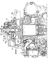
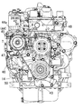
図1に示すように、シリンダブロック(14)の上部にシリンダヘッド(1)を組み付け、シリンダヘッド(1)の上部にヘッドカバー(2)を着脱自在に取り付けている。ヘッドカバー(2)内に位置するシリンダヘッド(1)のノズル取付孔(3)に燃料噴射ノズル(4)を取り付け、燃料噴射ノズル(4)に燃料入口(5)と燃料戻し出口(6)とを設けている。燃料タンクから燃料供給ポンプ(7)とコモンレール(8)と燃料供給パイプ(9)とを順に介して燃料噴射ノズル(4)の燃料入口(5)に燃料を供給し、燃料噴射ノズル(4)に供給した燃料の一部を燃料戻し出口(6)から燃料戻しパイプ(10)を介して燃料タンクに戻すように構成している。燃料は燃料供給ポンプ(7)に戻すようにしてもよい。
The outline of this engine is as follows.
As shown in FIG. 1, the cylinder head (1) is assembled to the upper part of the cylinder block (14), and the head cover (2) is detachably attached to the upper part of the cylinder head (1). A fuel injection nozzle (4) is attached to the nozzle mounting hole (3) of the cylinder head (1) located in the head cover (2), and a fuel inlet (5) and a fuel return outlet (6) are connected to the fuel injection nozzle (4). Is provided. Fuel is supplied from the fuel tank to the fuel inlet (5) of the fuel injection nozzle (4) through the fuel supply pump (7), the common rail (8) and the fuel supply pipe (9) in this order. A part of the fuel supplied to the fuel is returned from the fuel return outlet (6) to the fuel tank via the fuel return pipe (10). The fuel may be returned to the fuel supply pump (7).
燃料噴射ノズル(4)に対する配管は、次の通りである。
図1に示すように、燃料供給パイプ(9)を燃料噴射ノズル(4)の燃料入口(5)に接続し、燃料噴射ノズル(4)の燃料戻し出口(6)に燃料戻しパイプ(10)を接続するに当たり、燃料噴射ノズル(4)の燃料入口(5)と燃料戻し出口(6)とをヘッドカバー(2)内に配置している。燃料供給パイプ(9)の出口にノズル接続部(9a)を設け、ヘッドカバー(2)の壁に接続部貫通孔(11)を設け、接続部貫通孔(11)に貫通させたノズル接続部(9a)を燃料噴射ノズル(4)の燃料入口(5)に着脱自在に接続している。接続部貫通孔(11)はヘッドカバー(2)の周壁に形成されている。燃料噴射ノズル(4)の燃料入口(5)と燃料戻し出口(6)とは、燃料噴射ノズル(4)の周側から同じ方向に向けて突出させている。この燃料噴射ノズル(4)はインジェクタとも呼ばれるものである。
The piping for the fuel injection nozzle (4) is as follows.
As shown in FIG. 1, the fuel supply pipe (9) is connected to the fuel inlet (5) of the fuel injection nozzle (4), and the fuel return pipe (10) is connected to the fuel return outlet (6) of the fuel injection nozzle (4). Are connected, the fuel inlet (5) and the fuel return outlet (6) of the fuel injection nozzle (4) are arranged in the head cover (2). A nozzle connection portion (9a) is provided at the outlet of the fuel supply pipe (9), a connection portion through hole (11) is provided in the wall of the head cover (2), and a nozzle connection portion (through the connection portion through hole (11)) ( 9a) is detachably connected to the fuel inlet (5) of the fuel injection nozzle (4). The connecting portion through hole (11) is formed in the peripheral wall of the head cover (2). The fuel inlet (5) and the fuel return outlet (6) of the fuel injection nozzle (4) are projected in the same direction from the peripheral side of the fuel injection nozzle (4). This fuel injection nozzle (4) is also called an injector.
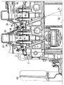
図2〜3に示すように、燃料戻しパイプ(10)をヘッドカバー(2)内に収容し、シリンダヘッド(1)内にヘッド内燃料戻し通路(12)を形成し、燃料戻しパイプ(10)の出口(10a)をヘッド内燃料戻し通路(12)の入口に接続する。これにより、図1に示すように、燃料供給パイプ(9)のノズル接続部(9a)を燃料噴射ノズル(4)の燃料入口(5)から取り外して、ヘッドカバー(2)の接続部貫通孔(11)からヘッドカバー(2)外に抜き取った場合に、燃料噴射ノズル(4)と燃料戻しパイプ(10)を取り外すことなく、ヘッドカバー(2)をシリンダヘッド(1)から取り外すことができるようにしている。このエンジンは、動弁カム軸(13)をシリンダブロック(14)に配置した頭上弁エンジンである。ヘッド内燃料戻し通路(12)の出口は燃料タンクと連通させている。 As shown in FIGS. 2 to 3, the fuel return pipe (10) is accommodated in the head cover (2), the in-head fuel return passage (12) is formed in the cylinder head (1), and the fuel return pipe (10). The outlet (10a) is connected to the inlet of the in-head fuel return passage (12). Thereby, as shown in FIG. 1, the nozzle connection part (9a) of the fuel supply pipe (9) is removed from the fuel inlet (5) of the fuel injection nozzle (4), and the connection part through hole ( 11) When the head cover (2) is removed from the head cover (2), the head cover (2) can be removed from the cylinder head (1) without removing the fuel injection nozzle (4) and the fuel return pipe (10). Yes. This engine is an overhead valve engine in which a valve camshaft (13) is arranged in a cylinder block (14). The outlet of the in-head fuel return passage (12) communicates with the fuel tank.
グロープラグ(16)の取付構造は、次の通りである。
図2に示すように、ヘッドカバー(2)の壁にグロープラグ挿通孔(15)をあけ、このグロープラグ挿通孔(15)にグロープラグ(16)を挿通し、グロープラグ挿通孔(15)とグロープラグ(16)との間を環状シール(17)で封止するに当たり、環状シール(17)をグロープラグ(16)に外嵌固定し、グロープラグ(16)のうち、ヘッドカバー(2)の外に突出する部分(18)の外径をグロープラグ挿通孔(15)の内径よりも小さくする。これにより、シリンダヘッド(1)からグロープラグ(16)を取り外すことなく、ヘッドカバー(2)をシリンダヘッド(1)に対して着脱できるようにしている。グロープラグ挿通孔(15)はヘッドカバー(2)の天井壁に形成している。
The attachment structure of the glow plug (16) is as follows.
As shown in FIG. 2, a glow plug insertion hole (15) is formed in the wall of the head cover (2), a glow plug (16) is inserted into the glow plug insertion hole (15), and a glow plug insertion hole (15) is formed. In sealing the gap between the glow plug (16) with the annular seal (17), the annular seal (17) is fitted and fixed to the glow plug (16), and the head cover (2) of the glow plug (16) is fixed. The outer diameter of the protruding portion (18) is made smaller than the inner diameter of the glow plug insertion hole (15). Thus, the head cover (2) can be attached to and detached from the cylinder head (1) without removing the glow plug (16) from the cylinder head (1). The glow plug insertion hole (15) is formed in the ceiling wall of the head cover (2).
グロープラグ(16)に関連する構造は、次の通りである。
図2に示すように、グロープラグ(16)のうち、ヘッドカバー(2)の外に突出する部分(18)に工具係合部(19)を設けている。シリンダヘッド(1)に複数のグロープラグ(16)を取り付けるに当たり、各グロープラグ(16)をシリンダ中心軸線(20)に対して所定角度(21)だけ同じ方向に傾け、ヘッドカバー(2)の壁にグロープラグ(16)と平行な向きのグロープラグ挿通孔(15)をあけている。グロープラグ(16)のうち、ヘッドカバー(2)の外に突出する部分(18)に端子(22)を設けている。ヘッドカバー(2)の壁のうち、グロープラグ(16)を貫通させた部分(23)をシリンダヘッド(1)に向けて後退させ、この壁の部分(23)の後退に伴ってヘッドカバー(2)外に形成された凹部空間(24)内にグロープラグ(16)の端子(22)を配置している。
The structure related to the
As shown in FIG. 2, a tool engaging portion (19) is provided on a portion (18) of the glow plug (16) that protrudes outside the head cover (2). When attaching a plurality of glow plugs (16) to the cylinder head (1), each glow plug (16) is inclined in the same direction by a predetermined angle (21) with respect to the cylinder center axis (20), and the wall of the head cover (2) A glow plug insertion hole (15) is formed in a direction parallel to the glow plug (16). A terminal (22) is provided on a portion (18) of the glow plug (16) protruding outside the head cover (2). Of the wall of the head cover (2), the portion (23) through which the glow plug (16) has passed is retracted toward the cylinder head (1), and as the wall portion (23) is retracted, the head cover (2) A terminal (22) of the glow plug (16) is disposed in a recessed space (24) formed outside.
部品配置は、次の通りである。
図1に示すように、エンジンの幅方向を横方向として、エンジンの横一側方にコモンレール(8)を配置するに当たり、燃料噴射ノズル(4)の燃料入口(5)を有する入口管(5a)と、燃料戻し出口(6)を有する出口管(6a)とを、いずれもコモンレール(8)を配置したエンジンの横一側方に向けて突出させている。この出口管(6a)には、燃料戻しパイプ(10)の環状継手を取り付けている。また、コモンレール(8)を配置したエンジンの横一側方にコモンレール(8)用の燃料供給ポンプ(7)を配置している。コモンレール(8)は、前後方向に向けて架設され、その前端部には圧力センサが配置され、その後端部にはリリーフ弁が配置されている。
The component arrangement is as follows.
As shown in FIG. 1, when a common rail (8) is arranged on one side of the engine with the width direction of the engine as a lateral direction, an inlet pipe (5a) having a fuel inlet (5) of a fuel injection nozzle (4) is provided. ) And an outlet pipe (6a) having a fuel return outlet (6), both project toward the lateral side of the engine on which the common rail (8) is disposed. An annular joint of the fuel return pipe (10) is attached to the outlet pipe (6a). Further, a fuel supply pump (7) for the common rail (8) is arranged on one lateral side of the engine on which the common rail (8) is arranged. The common rail (8) is erected in the front-rear direction, a pressure sensor is disposed at the front end thereof, and a relief valve is disposed at the rear end thereof.
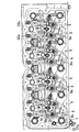
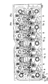
図3に示すように、ヘッド内燃料戻し通路(12)の通路出口を有する通路出口管(12a)を、コモンレール(8)を配置したエンジンの横一側方に配置している。図3、図4に示すように、複数のバルブ(31)(31)(32)(32)を同期させて開閉するバルブブリッジ(33)(34)に各バルブ(31)(31)(32)(32)の当たり面の高さを調節するブリッジ調整部(33a)(34a)を設け、ロッカアーム(35)(36)にロッカアーム(35)(36)とブッシュロッド(37)(38)との隙間を調節するアーム調節部(35a)(36a)を設け、コモンレール(8)を配置したエンジンの横一側方寄りにブリッジ調節部(33a)(34a)を配置し、横他側方寄りにアーム調節部(35a)(36a)を配置し、アーム調節部(35a)(36a)の調節操作部(35b)(36b)をブリッジ調節部(33a)(34a)の調節操作部(33b)(34b)よりも高い位置に配置している。図中の符号(31)は吸気バルブ、(32)は排気バルブ、(33)は吸気バルブブリッジ、(35)は吸気用ロッカアーム、(36)は排気用ロッカアーム、(37)は吸気用プッシュロッド、(38)は排気用プッシュロッドである。吸気バルブ(31)と排気バルブ(32)は1気筒毎に2個ずつ配置されている。ブリッジ調節部(33a)(34a)とアーム調節部(35a)(36a)とは、いずれもオネジ杆とロックナットからなり、これらの各調整操作部とは、オネジ杆の上端のすり割りとロックナットとをいう。 As shown in FIG. 3, a passage outlet pipe (12a) having a passage outlet of the in-head fuel return passage (12) is arranged on one lateral side of the engine on which the common rail (8) is arranged. As shown in FIGS. 3 and 4, each valve (31) (31) (32) is connected to a valve bridge (33) (34) that opens and closes a plurality of valves (31) (31) (32) (32) in synchronization. ) (32) is provided with a bridge adjusting portion (33a) (34a) for adjusting the height of the contact surface, and the rocker arms (35) (36) are provided with the rocker arms (35) (36) and bush rods (37) (38). Arm adjustment part (35a) (36a) that adjusts the clearance of the rail is provided, and the bridge adjustment part (33a) (34a) is arranged near the lateral side of the engine on which the common rail (8) is arranged, and the lateral side of the engine The arm adjusting portions (35a) and (36a) are arranged in the arm adjusting portions (35a) and (36a), and the adjusting operation portions (35b) and (36b) of the arm adjusting portions (35a) and (36a) are adjusted. It is arranged at a position higher than (34b). In the figure, reference numeral (31) is an intake valve, (32) is an exhaust valve, (33) is an intake valve bridge, (35) is an intake rocker arm, (36) is an exhaust rocker arm, and (37) is an intake push rod. , (38) are exhaust push rods. Two intake valves (31) and two exhaust valves (32) are arranged for each cylinder. Each of the bridge adjusting portions (33a) (34a) and the arm adjusting portions (35a) (36a) is composed of a male screw rod and a lock nut, and each of these adjusting operation portions is divided and locked at the upper end of the male screw rod. A nut.
図1に示すように、吸気分配手段(39)をコモンレール(8)の上方に配置している。吸気分配手段(39)に代えて、排気合流手段(48) をコモンレール(8)の上方に配置してもよい。すなわち、吸気分配手段(39)と排気合流手段(48)のいずれかから選択される通路形成手段(49)をコモンレール(8)の上方に配置すればよい。コモンレール(8)上方の通路形成手段(49)を、分岐管のない箱型構造としている。図5〜図7に示すように、クランク軸(28)の架設方向を前後方向とし、その一方を前、他方を後とし、コモンレール(8)の前方にエンジン冷却ファン(42)を配置し、コモンレール(8)上方の通路形成手段(49)の下方を風が通過するようにしている。 As shown in FIG. 1, the intake air distribution means (39) is disposed above the common rail (8). Instead of the intake air distribution means (39), the exhaust gas merging means (48) may be arranged above the common rail (8). That is, the passage forming means (49) selected from either the intake distribution means (39) or the exhaust merging means (48) may be disposed above the common rail (8). The passage forming means (49) above the common rail (8) has a box structure without a branch pipe. As shown in FIGS. 5 to 7, the installation direction of the crankshaft (28) is the front-rear direction, one of which is the front and the other is the rear, and the engine cooling fan (42) is disposed in front of the common rail (8), The wind passes below the passage forming means (49) above the common rail (8).
吸気分配手段(39)は吸気マニホルドに相当するものであるが、分岐管がないため、このような部品名とした。排気合流手段(48)は、排気マニホルドに相当するものであるが、吸気分配手段という部品名に合わせるため、このような部品名とした。図7に示すように、コモンレール(8)の前方には、ベルトテンショナ(44)となる発電機(45)やそのステー(44a)が配置されているが、エンジン冷却ファン(42)で後向きに送られる風は、発電機(45)とシリンダブロック(14)との隙間やステー(44a)の上方を通過して、通路形成手段(49)の下方に供給される。このエンジン冷却ファン(42)はラジエータファンである。 The intake air distribution means (39) corresponds to an intake manifold, but since there is no branch pipe, it is given such a part name. The exhaust merging means (48) is equivalent to an exhaust manifold, but in order to match the part name of the intake air distributing means, such a part name is used. As shown in FIG. 7, a generator (45) serving as a belt tensioner (44) and its stay (44a) are arranged in front of the common rail (8), and the engine cooling fan (42) faces backward. The wind to be sent passes through the gap between the generator (45) and the cylinder block (14) and the upper part of the stay (44a) and is supplied below the passage forming means (49). The engine cooling fan (42) is a radiator fan.
図1、図4(A)、図6、図7に示すように、コモンレール(8)上方の通路形成手段(49)を、分岐管のない箱型構造とし、その下壁(39a)に取付ボルト(30)のボス(30a)を設け、このボス(30a)を通路形成手段(49)の下壁(39a)から下向きに突出させるとともに、このボス(30a)が通路形成手段(49)の下壁(39a)を横向きに横断するようにしている。 As shown in FIG. 1, FIG. 4 (A), FIG. 6, and FIG. 7, the passage forming means (49) above the common rail (8) has a box structure without a branch pipe and is attached to the lower wall (39a). A boss (30a) of the bolt (30) is provided, and this boss (30a) protrudes downward from the lower wall (39a) of the passage forming means (49), and this boss (30a) serves as the passage forming means (49). The lower wall (39a) is traversed sideways.
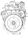
図5に示すように、エンジンの後部にコモンレール(8)用の燃料供給ポンプ(7)を連動するギヤトレイン(40)を配置し、ギヤトレイン(40)をギヤトレイン収容部(41)に収容し、ギヤトレイン収容部(41)の一部を横向きに突出させ、この突出部(41a)の前面にコモンレール(8)用の燃料供給ポンプ(7)を取り付け、図8に示すように、コモンレール(8)の後端部にその後方からギヤトレイン収容部(41)の突出部(41a)を臨ませている。 As shown in FIG. 5, a gear train (40) interlocking with a fuel supply pump (7) for the common rail (8) is disposed at the rear of the engine, and the gear train (40) is accommodated in the gear train accommodating portion (41). Then, a part of the gear train housing part (41) is projected sideways, and a fuel supply pump (7) for the common rail (8) is attached to the front surface of the projecting part (41a), and as shown in FIG. (8) The protrusion part (41a) of the gear train accommodating part (41) is made to face from the rear to the rear end part.
図6に示すように、エンジンの前部にベルト伝動装置(43)を配置し、エンジンの後部にコモンレール(8)用の燃料供給ポンプ(7)を連動するギヤトレイン(40)を配置し、ギヤトレイン(40)をギヤトレイン収容部(41)に収容し、ギヤトレイン収容部(41)の一部を横向きに突出させ、この突出部(41a)の前面にコモンレール(8)用の燃料供給ポンプ(7)を取り付け、この燃料供給ポンプ(7)の前方にベルト伝動装置(43)のベルトテンショナ(44)を配置している。この実施形態では、発電機(45)をベルトテンショナ(44)としている。 As shown in FIG. 6, a belt transmission (43) is arranged at the front part of the engine, and a gear train (40) interlocking with the fuel supply pump (7) for the common rail (8) is arranged at the rear part of the engine. The gear train (40) is accommodated in the gear train accommodating part (41), a part of the gear train accommodating part (41) is projected sideways, and fuel for the common rail (8) is supplied to the front surface of the projecting part (41a). A pump (7) is attached, and a belt tensioner (44) of the belt transmission (43) is disposed in front of the fuel supply pump (7). In this embodiment, the generator (45) is a belt tensioner (44).
図6に示すように、コモンレール(8)のある側で、コモンレール(8)用の燃料供給ポンプ(7)を、シリンダブロック(14)の上寄り部分(14a)の横一側方に配置している。また、コモンレール(8)のある側で、シリンダブロック(14)の上下方向中央部(14b)の横一側に、オイルクーラ(46)とスタータモータ(47)とを前後に振り分けて配置している。また、コモンレール(8)のある側には、オイルクーラ(46)の後部に取り付けたオイルフィルタ(51)、スタータモータ(47)とオイルフィルタ(51)との間に配置されたオイルレベルゲージ(52)や燃料フィルタ(53)等がある。 As shown in FIG. 6, the fuel supply pump (7) for the common rail (8) is arranged on one side of the upper portion (14a) of the cylinder block (14) on the side with the common rail (8). ing. Also, on the side where the common rail (8) is located, the oil cooler (46) and the starter motor (47) are arranged in the front-rear direction on one side of the vertical center (14b) of the cylinder block (14). Yes. Further, on the side where the common rail (8) is located, an oil filter (51) attached to the rear part of the oil cooler (46), an oil level gauge (between the starter motor (47) and the oil filter (51)) ( 52) and a fuel filter (53).
上記のエンジンを製造する方法は、次の通りである。
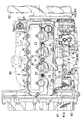
図9〜図10に示す燃料噴射カムで燃料噴射を行う機械制御噴射式ディーゼルエンジンのヘッドカバー(2)とシリンダヘッド(1)とシリンダブロック(14)を転用して、図1〜図8に示すコモンレール式ディーゼルエンジンを製造する。
機械制御噴射式ディーゼルエンジンとコモンレール式ディーゼルエンジンとは、いずれも次の構造を備えている。
シリンダヘッド(1)にヘッドカバー(2)を着脱自在に取り付け、ヘッドカバー(2)内に位置するシリンダヘッド(1)のノズル取付孔(3)に燃料噴射ノズル(4)を取り付け、燃料噴射ノズル(4)に燃料入口(5)と燃料戻し出口(6)とを設け、燃料供給パイプ(9)を介して燃料噴射ノズル(4)の燃料入口(5)に燃料を供給し、燃料噴射ノズル(4)に供給した燃料の一部を燃料戻し出口(6)から燃料戻しパイプ(10)を介して燃料タンクに戻すように構成している。燃料は燃料供給ポンプ(7)や燃料噴射ポンプ(54)に戻すようにしてもよい。
The method for manufacturing the engine is as follows.
A head cover (2), a cylinder head (1), and a cylinder block (14) of a mechanically controlled injection type diesel engine that performs fuel injection with the fuel injection cam shown in FIGS. 9 to 10 are shown in FIGS. Manufactures common rail diesel engines.
Both the machine-controlled injection diesel engine and the common rail diesel engine have the following structure.
The head cover (2) is detachably attached to the cylinder head (1), the fuel injection nozzle (4) is attached to the nozzle mounting hole (3) of the cylinder head (1) located in the head cover (2), and the fuel injection nozzle ( 4) is provided with a fuel inlet (5) and a fuel return outlet (6). Fuel is supplied to the fuel inlet (5) of the fuel injection nozzle (4) via the fuel supply pipe (9), and the fuel injection nozzle ( Part of the fuel supplied to 4) is returned from the fuel return outlet (6) to the fuel tank via the fuel return pipe (10). The fuel may be returned to the fuel supply pump (7) or the fuel injection pump (54).
燃料供給パイプ(9)を燃料噴射ノズル(4)の燃料入口(5)に接続し、燃料噴射ノズル(4)の燃料戻し出口(6)に燃料戻しパイプ(10)を接続するに当たり、燃料噴射ノズル(4)の燃料入口(5)と燃料戻し出口(6)とをヘッドカバー(2)内に配置し、燃料供給パイプ(9)の出口にノズル接続部(9a)を設け、ヘッドカバー(2)の壁に接続部貫通孔(11)を設け、接続部貫通孔(11)に貫通させたノズル接続部(9a)を燃料噴射ノズル(4)の燃料入口(5)に着脱自在に接続している。 In connecting the fuel supply pipe (9) to the fuel inlet (5) of the fuel injection nozzle (4) and connecting the fuel return pipe (10) to the fuel return outlet (6) of the fuel injection nozzle (4), the fuel injection A fuel inlet (5) and a fuel return outlet (6) of the nozzle (4) are arranged in the head cover (2), and a nozzle connecting portion (9a) is provided at the outlet of the fuel supply pipe (9), so that the head cover (2) A connecting part through hole (11) is provided in the wall of the nozzle, and a nozzle connecting part (9a) penetrating the connecting part through hole (11) is detachably connected to the fuel inlet (5) of the fuel injection nozzle (4). Yes.
燃料戻しパイプ(10)をヘッドカバー(2)内に収容し、シリンダヘッド(1)内にヘッド内燃料戻し通路(12)を形成し、燃料戻しパイプ(10)の出口(10a)をヘッド内燃料戻し通路(12)の入口に接続することにより、燃料供給パイプ(9)のノズル接続部(9a)を燃料噴射ノズル(4)の燃料入口(5)から取り外して、ヘッドカバー(2)の接続部貫通孔(11)からヘッドカバー(2)外に抜き取った場合に、燃料噴射ノズル(4)と燃料戻しパイプ(10)を取り外すことなく、ヘッドカバー(2)をシリンダヘッド(1)から取り外すことができるようにしている。なお、図9、図10中、コモンレール式ディーゼルエンジンと同じ要素には、同じ符号を付しておく。 The fuel return pipe (10) is accommodated in the head cover (2), the in-head fuel return passage (12) is formed in the cylinder head (1), and the outlet (10a) of the fuel return pipe (10) is connected to the fuel in the head. By connecting to the inlet of the return passage (12), the nozzle connecting part (9a) of the fuel supply pipe (9) is removed from the fuel inlet (5) of the fuel injection nozzle (4), and the connecting part of the head cover (2) When the head cover (2) is extracted from the through hole (11), the head cover (2) can be removed from the cylinder head (1) without removing the fuel injection nozzle (4) and the fuel return pipe (10). I am doing so. In FIG. 9 and FIG. 10, the same reference numerals are given to the same elements as those of the common rail type diesel engine.
この製造方法においては、図1に示すように、ヘッドカバー(2)の壁にコネクタ挿通孔(25)をあけ、このコネクタ挿通孔(25)から燃料噴射ノズル(4)のコネクタ(26)をヘッドカバー(2)外に突出させ、このコネクタ(26)をヘッドカバー(2)の壁に取り付けたコネクタカバー(27)で覆う。コネクタ(26)は燃料噴射ノズル(4)の電磁弁に通電と制御のための電気回路を接続するためのものである。 In this manufacturing method, as shown in FIG. 1, a connector insertion hole (25) is formed in the wall of the head cover (2), and the connector (26) of the fuel injection nozzle (4) is connected to the head cover through the connector insertion hole (25). (2) Project outside and cover this connector (26) with a connector cover (27) attached to the wall of the head cover (2). The connector (26) is for connecting an electric circuit for energization and control to the solenoid valve of the fuel injection nozzle (4).
(1)…シリンダヘッド、(2)…ヘッドカバー、(3)…ノズル取付孔、(4)…燃料噴射ノズル、(5)…燃料入口、(5a)…入口管、(6)…燃料戻し出口、(6a)…出口管、(7)…燃料供給ポンプ、(8)…コモンレール、(9)…燃料供給パイプ、(9a)…ノズル接続部、(10)…燃料戻しパイプ、(10a)…出口、(11)…接続部貫通孔、(12)…ヘッド内燃料戻し通路、(12a)…通路出口管、(13)…動弁カム軸、(14)…シリンダブロック、(14a)…上寄り部分、(14b)…上下方向中央部、(15)…グロープラグ挿通孔、(16)…グロープラグ、(17)…環状シール、(18)…外に突出する部分、(19)…工具係合部、(20)…シリンダ中心軸線、(21)…所定角度、(22)…端子、(23)…壁の部分、(24)…凹部空間、(25)…コネクタ挿通孔、(26)…コネクタ、(27)…コネクタカバー、(28)…クランク軸、(30)…取付ボルト、(30a)…ボス、(31)吸気バルブ、(32)排気バルブ、(33)吸気バルブブリッジ、(33a)…ブリッジ調節部、(33b)…調節操作部、(34)排気バルブブリッジ、(34a)…ブリッジ調節部、(34b)…調節操作部、(35)吸気用ロッカアーム、(35a)…アーム調節部、(35b)…調節操作部、(36)排気用ロッカアーム、(36a)…アーム調節部、(36b)…調節操作部、(37)吸気用プッシュロッド、(38)排気用プッシュロッド、(39)吸気分配手段、(39a)…下壁、(40)ギヤトレイン、(41)ギヤトレイン収容部、(41a)…突出部、(42)…エンジン冷却ファン、(43)…ベルト伝動装置、(44)…ベルトテンショナ、(45)…発電機、(46)…オイルクーラ、(47)…スタータモータ、(49)…通路形成手段。
(1) ... Cylinder head, (2) ... Head cover, (3) ... Nozzle mounting hole, (4) ... Fuel injection nozzle, (5) ... Fuel inlet, (5a) ... Inlet pipe, (6) ... Fuel return outlet (6a) ... exit pipe, (7) ... fuel supply pump, (8) ... common rail, (9) ... fuel supply pipe, (9a) ... nozzle connection, (10) ... fuel return pipe, (10a) ... Outlet, (11) ... Connector through hole, (12) ... In-head fuel return passage, (12a) ... Passage outlet pipe, (13) ... Valve camshaft, (14) ... Cylinder block, (14a) ... Up (14b) ... Center part in the vertical direction, (15) ... Glow plug insertion hole, (16) ... Glow plug, (17) ... Ring seal, (18) ... Part protruding outward, (19) ... Tool (20) ... Cylinder center axis, (21) ... Predetermined angle, (22) ... Terminal, (23) ... Wall portion, (24) ... Recessed space, (25) ... Connector insertion hole, (26 ) ... (27) ... connector cover, (28) ... crankshaft, (30) ... mounting bolt, (30a) ... boss, (31) intake valve, (32) exhaust valve, (33) intake valve bridge, (33a ) ... Bridge adjustment part, (33b) ... Adjustment operation part, (34) Exhaust valve bridge, (34a) ... Bridge adjustment part, (34b) ... Adjustment operation part, (35) Intake rocker arm, (35a) ... Arm adjustment (35b) ... adjustment operation part, (36) exhaust rocker arm, (36a) ... arm adjustment part, (36b) ... adjustment operation part, (37) intake push rod, (38) exhaust push rod, 39) Intake distribution means, (39a) ... lower wall, (40) gear train, (41) gear train housing, (41a) ... projecting part, (42) ... engine cooling fan, (43) ... belt transmission, (44) ... Belt tensioner, (45) ... Generator, (46) ... Oil cooler , (47) ... starter motor, (49) ... passage forming means.
Claims (22)
燃料供給パイプ(9)を燃料噴射ノズル(4)の燃料入口(5)に接続し、燃料噴射ノズル(4)の燃料戻し出口(6)に燃料戻しパイプ(10)を接続するに当たり、燃料噴射ノズル(4)の燃料入口(5)と燃料戻し出口(6)とをヘッドカバー(2)内に配置し、
燃料供給パイプ(9)の出口にノズル接続部(9a)を設け、ヘッドカバー(2)の壁に接続部貫通孔(11)を設け、接続部貫通孔(11)に貫通させたノズル接続部(9a)を燃料噴射ノズル(4)の燃料入口(5)に着脱自在に接続し、
燃料戻しパイプ(10)をヘッドカバー(2)内に収容し、シリンダヘッド(1)内にヘッド内燃料戻し通路(12)を形成し、燃料戻しパイプ(10)の出口(10a)をヘッド内燃料戻し通路(12)の入口に接続することにより、
燃料供給パイプ(9)のノズル接続部(9a)を燃料噴射ノズル(4)の燃料入口(5)から取り外して、ヘッドカバー(2)の接続部貫通孔(11)からヘッドカバー(2)外に抜き取った場合に、燃料噴射ノズル(4)と燃料戻しパイプ(10)を取り外すことなく、ヘッドカバー(2)をシリンダヘッド(1)から取り外すことができるようにした、ことを特徴するコモンレール式ディーゼルエンジン。 The head cover (2) is detachably attached to the cylinder head (1), the fuel injection nozzle (4) is attached to the nozzle mounting hole (3) of the cylinder head (1) located in the head cover (2), and the fuel injection nozzle ( 4) is provided with a fuel inlet (5) and a fuel return outlet (6), and a fuel injection nozzle (4) from the fuel tank through a fuel supply pump (7), a common rail (8) and a fuel supply pipe (9) in this order. ) Is supplied to the fuel inlet (5), and a part of the fuel supplied to the fuel injection nozzle (4) is supplied from the fuel return outlet (6) to the fuel tank or the fuel supply pump (10) via the fuel return pipe (10). In the common rail diesel engine configured to return to 7),
In connecting the fuel supply pipe (9) to the fuel inlet (5) of the fuel injection nozzle (4) and connecting the fuel return pipe (10) to the fuel return outlet (6) of the fuel injection nozzle (4), the fuel injection The fuel inlet (5) and the fuel return outlet (6) of the nozzle (4) are arranged in the head cover (2),
A nozzle connection portion (9a) is provided at the outlet of the fuel supply pipe (9), a connection portion through hole (11) is provided in the wall of the head cover (2), and a nozzle connection portion (through the connection portion through hole (11)) ( 9a) is detachably connected to the fuel inlet (5) of the fuel injection nozzle (4),
The fuel return pipe (10) is accommodated in the head cover (2), the in-head fuel return passage (12) is formed in the cylinder head (1), and the outlet (10a) of the fuel return pipe (10) is connected to the fuel in the head. By connecting to the entrance of the return passage (12)
The nozzle connection part (9a) of the fuel supply pipe (9) is removed from the fuel inlet (5) of the fuel injection nozzle (4), and is pulled out of the head cover (2) from the connection part through hole (11) of the head cover (2). In this case, the common rail diesel engine is characterized in that the head cover (2) can be removed from the cylinder head (1) without removing the fuel injection nozzle (4) and the fuel return pipe (10).
動弁カム軸(13)をシリンダブロック(14)に配置した頭上弁エンジンに適用する、ことを特徴とするコモンレール式ディーゼルエンジン。 In the common rail type diesel engine according to claim 1,
A common rail diesel engine characterized by being applied to an overhead valve engine in which a valve camshaft (13) is arranged in a cylinder block (14).
ヘッドカバー(2)の壁にグロープラグ挿通孔(15)をあけ、このグロープラグ挿通孔(15)にグロープラグ(16)を挿通し、グロープラグ挿通孔(15)とグロープラグ(16)との間を環状シール(17)で封止するに当たり、
環状シール(17)をグロープラグ(16)に外嵌固定し、グロープラグ(16)のうち、ヘッドカバー(2)の外に突出する部分(18)の外径をグロープラグ挿通孔(15)の内径よりも小さくすることにより、シリンダヘッド(1)からグロープラグ(16)を取り外すことなく、ヘッドカバー(2)をシリンダヘッド(1)に対して着脱できるようにした、ことを特徴するコモンレール式ディーゼルエンジン。 In the common rail type diesel engine according to claim 1 or 2,
A glow plug insertion hole (15) is formed in the wall of the head cover (2), the glow plug (16) is inserted into the glow plug insertion hole (15), and the glow plug insertion hole (15) and the glow plug (16) are connected to each other. When sealing the space with the annular seal (17),
The annular seal (17) is fitted and fixed to the glow plug (16), and the outer diameter of the portion (18) protruding out of the head cover (2) of the glow plug (16) is set in the glow plug insertion hole (15). The common rail diesel, characterized in that the head cover (2) can be attached to and detached from the cylinder head (1) without removing the glow plug (16) from the cylinder head (1) by making it smaller than the inner diameter. engine.
グロープラグ(16)のうち、ヘッドカバー(2)の外に突出する部分(18)に工具係合部(19)を設けた、ことを特徴とするコモンレール式ディーゼルエンジン。 In the common rail type diesel engine according to claim 3,
A common rail type diesel engine characterized in that a tool engaging portion (19) is provided on a portion (18) of the glow plug (16) protruding outside the head cover (2).
シリンダヘッド(1)に複数のグロープラグ(16)を取り付けるに当たり、
各グロープラグ(16)をシリンダ中心軸線(20)に対して所定角度(21)だけ同じ方向に傾け、ヘッドカバー(2)の壁にグロープラグ(16)と平行な向きのグロープラグ挿通孔(15)をあけた、ことを特徴とするコモンレール式ディーゼルエンジン。 In the common rail type diesel engine according to claim 3 or 4,
In attaching a plurality of glow plugs (16) to the cylinder head (1),
Each glow plug (16) is inclined in the same direction by a predetermined angle (21) with respect to the cylinder center axis (20), and a glow plug insertion hole (15) parallel to the glow plug (16) is formed in the wall of the head cover (2). ), A common rail diesel engine characterized by that.
グロープラグ(16)のうち、ヘッドカバー(2)の外に突出する部分(18)に端子(22)を設けた、ことを特徴とするコモンレール式ディーゼルエンジン。 In the common rail type diesel engine according to any one of claims 3 to 6,
A common rail type diesel engine characterized in that a terminal (22) is provided on a portion (18) of the glow plug (16) protruding outside the head cover (2).
ヘッドカバー(2)の壁のうち、グロープラグ(16)を貫通させた部分(23)をシリンダヘッド(1)に向けて後退させ、この壁の部分(23)の後退に伴ってヘッドカバー(2)外に形成された凹部空間(24)内にグロープラグ(16)の端子(22)を配置した、ことを特徴とするコモンレール式ディーゼルエンジン。 In the common rail type diesel engine according to claim 6,
Of the wall of the head cover (2), the portion (23) through which the glow plug (16) has passed is retracted toward the cylinder head (1), and as the wall portion (23) is retracted, the head cover (2) A common rail diesel engine characterized in that a terminal (22) of a glow plug (16) is disposed in a recessed space (24) formed outside.
エンジンの幅方向を横方向として、
エンジンの横一側方にコモンレール(8)を配置するに当たり、
燃料噴射ノズル(4)の燃料入口(5)を有する入口管(5a)と、燃料戻し出口(6)を有する出口管(6a)とを、いずれもコモンレール(8)を配置したエンジンの横一側方に向けて突出させた、ことを特徴とするコモンレール式ディーゼルエンジン。 In the common rail type diesel engine according to any one of claims 1 to 7,
With the width direction of the engine as the horizontal direction,
When placing the common rail (8) on one side of the engine,
The inlet pipe (5a) having the fuel inlet (5) of the fuel injection nozzle (4) and the outlet pipe (6a) having the fuel return outlet (6) are all arranged side by side in the engine in which the common rail (8) is arranged. A common rail type diesel engine that protrudes to the side.
コモンレール(8)を配置したエンジンの横一側方にコモンレール(8)用の燃料供給ポンプ(7)を配置した、ことを特徴とするコモンレール式ディーゼルエンジン。 In the common rail type diesel engine according to claim 8,
A common rail type diesel engine, characterized in that a fuel supply pump (7) for the common rail (8) is arranged on one lateral side of the engine on which the common rail (8) is arranged.
エンジンの幅方向を横方向として、
エンジンの横一側方にコモンレール(8)を配置するに当たり、
ヘッド内燃料戻し通路(12)の通路出口を有する通路出口管(12a)を、コモンレール(8)を配置したエンジンの横一側方に配置した、ことを特徴とするコモンレール式ディーゼルエンジン。 In the common rail type diesel engine according to any one of claims 1 to 9,
With the width direction of the engine as the horizontal direction,
When placing the common rail (8) on one side of the engine,
A common rail type diesel engine, characterized in that a passage outlet pipe (12a) having a passage outlet of a fuel return passage (12) in the head is arranged on one side of the engine on which the common rail (8) is arranged.
エンジンの幅方向を横方向として、
エンジンの横一側方にコモンレール(8)を配置するに当たり、
複数のバルブ(31)(31)(32)(32)を同期させて開閉するバルブブリッジ(33)(34)に各バルブ(31)(31)(32)(32)の当たり面の高さを調節するブリッジ調整部(33a)(34a)を設け、ロッカアーム(35)(36)にロッカアーム(35)(36)とブッシュロッド(37)(38)との隙間を調節するアーム調節部(35a)(36a)を設け、コモンレール(8)を配置したエンジンの横一側方寄りにブリッジ調節部(33a)(34a)を配置し、横他側方寄りにアーム調節部(35a)(36a)を配置し、アーム調節部(35a)(36a)の調節操作部(35b)(36b)をブリッジ調節部(33a)(34a)の調節操作部(33b)(34b)よりも高い位置に配置した、ことを特徴とするコモンレール式ディーゼルエンジン。 In the common rail type diesel engine according to any one of claims 1 to 10,
With the width direction of the engine as the horizontal direction,
When placing the common rail (8) on one side of the engine,
The height of the contact surface of each valve (31) (31) (32) (32) to the valve bridge (33) (34) that opens and closes the plurality of valves (31) (31) (32) (32) in synchronization. Bridge adjusting portions (33a) and (34a) for adjusting the arm and adjusting the clearance between the rocker arms (35) and (36) and the bush rods (37) and (38) in the rocker arms (35 and 36). ) (36a), a bridge adjustment part (33a) (34a) is arranged near one side of the engine where the common rail (8) is arranged, and an arm adjustment part (35a) (36a) is arranged near the other side. The adjustment operation portions (35b) and (36b) of the arm adjustment portions (35a) and (36a) are arranged at positions higher than the adjustment operation portions (33b) and (34b) of the bridge adjustment portions (33a) and (34a). This is a common rail diesel engine.
エンジンの幅方向を横方向として、
エンジンの横側方にコモンレール(8)を配置するに当たり、
吸気分配手段(39)と排気合流手段(48)のいずれかから選択される通路形成手段(49)をコモンレール(8)の上方に配置した、ことを特徴とするコモンレール式ディーゼルエンジン。 In the common rail type diesel engine according to any one of claims 1 to 11,
With the width direction of the engine as the horizontal direction,
When placing the common rail (8) on the side of the engine,
A common rail type diesel engine, characterized in that a passage forming means (49) selected from either an intake air distributing means (39) or an exhaust merging means (48) is disposed above the common rail (8).
コモンレール(8)上方の通路形成手段(49)を、分岐管のない箱型構造とした、ことを特徴とするコモンレール式ディーゼルエンジン。 In the common rail type diesel engine according to claim 12,
A common rail diesel engine characterized in that the passage forming means (49) above the common rail (8) has a box-type structure without a branch pipe.
クランク軸(28)の架設方向を前後方向とし、その一方を前、他方を後とし、
コモンレール(8)の前方にエンジン冷却ファン(42)を配置し、コモンレール(8)上方の通路形成手段(49)の下方を冷却風が通過するようにした、ことを特徴とするコモンレール式ディーゼルエンジン。 In the common rail type diesel engine according to claim 12 or 13,
The installation direction of the crankshaft (28) is the front-rear direction, one of which is the front, the other is the rear,
An engine cooling fan (42) is arranged in front of the common rail (8), and the cooling air passes below the passage forming means (49) above the common rail (8). .
コモンレール(8)上方の通路形成手段(49)を、分岐管のない箱型構造とし、その下壁(39a)に取付ボルト(30)のボス(30a)を設け、このボス(30a)を通路形成手段(49)の下壁(39a)から下向きに突出させるとともに、このボス(30a)が通路形成手段(49)の下壁(39a)を横向きに横断するようにした、ことを特徴とするコモンレール式ディーゼルエンジン。 In the common rail type diesel engine according to claim 14,
The passage forming means (49) above the common rail (8) has a box structure without a branch pipe, and a boss (30a) of a mounting bolt (30) is provided on the lower wall (39a), and this boss (30a) is connected to the passage. The boss (30a) protrudes downward from the lower wall (39a) of the forming means (49) and crosses the lower wall (39a) of the passage forming means (49) laterally. Common rail diesel engine.
エンジンの幅方向を横方向として、
エンジンの横一側方にコモンレール(8)を配置するに当たり、
クランク軸(28)の架設方向を前後方向とし、その一方を前、他方を後とし、
エンジンの後部にコモンレール(8)用の燃料供給ポンプ(7)を連動するギヤトレイン(40)を配置し、ギヤトレイン(40)をギヤトレイン収容部(41)に収容し、ギヤトレイン収容部(41)の一部を横向きに突出させ、この突出部(41a)の前面にコモンレール(8)用の燃料供給ポンプ(7)を取り付け、コモンレール(8)の後端部にその後方からギヤトレイン収容部(41)の突出部(41a)を臨ませた、ことを特徴とするコモンレール式ディーゼルエンジン。 In the common rail type diesel engine according to any one of claims 1 to 15,
With the width direction of the engine as the horizontal direction,
When placing the common rail (8) on one side of the engine,
The installation direction of the crankshaft (28) is the front-rear direction, one of which is the front, the other is the rear,
A gear train (40) interlocking with the fuel supply pump (7) for the common rail (8) is disposed at the rear of the engine, the gear train (40) is accommodated in the gear train accommodating portion (41), and the gear train accommodating portion ( 41) is protruded sideways, a fuel supply pump (7) for the common rail (8) is attached to the front surface of the protruding portion (41a), and a gear train is accommodated at the rear end of the common rail (8) from behind. A common rail type diesel engine having a protruding portion (41a) facing the portion (41).
エンジンの幅方向を横方向として、
エンジンの横一側方にコモンレール(8)を配置するに当たり、
クランク軸(28)の架設方向を前後方向とし、その一方を前、他方を後とし、
エンジンの前部にベルト伝動装置(43)を配置し、エンジンの後部にコモンレール(8)用の燃料供給ポンプ(7)を連動するギヤトレイン(40)を配置し、ギヤトレイン(40)をギヤトレイン収容部(41)に収容し、ギヤトレイン収容部(41)の一部を横向きに突出させ、この突出部(41a)の前面にコモンレール(8)用の燃料供給ポンプ(7)を取り付け、この燃料供給ポンプ(7)の前方にベルト伝動装置(43)のベルトテンショナ(44)を配置した、ことを特徴とするコモンレール式ディーゼルエンジン。 In the common rail type diesel engine according to any one of claims 1 to 16,
With the width direction of the engine as the horizontal direction,
When placing the common rail (8) on one side of the engine,
The installation direction of the crankshaft (28) is the front-rear direction, one of which is the front, the other is the rear,
A belt transmission device (43) is arranged at the front of the engine, a gear train (40) interlocking with the fuel supply pump (7) for the common rail (8) is arranged at the rear of the engine, and the gear train (40) is geared. It is accommodated in the train accommodating part (41), a part of the gear train accommodating part (41) is projected sideways, and a fuel supply pump (7) for the common rail (8) is attached to the front surface of the projecting part (41a), A common rail type diesel engine having a belt tensioner (44) of a belt transmission (43) disposed in front of the fuel supply pump (7).
発電機(45)をベルトテンショナ(44)とした、ことを特徴とするコモンレール式ディーゼルエンジン。 In the common rail type diesel engine according to claim 17,
A common rail diesel engine characterized in that the generator (45) is a belt tensioner (44).
コモンレール(8)のある側で、コモンレール(8)用の燃料供給ポンプ(7)を、シリンダブロック(14)の上寄り部分(14a)の横一側方に配置した、ことを特徴とするコモンレール式ディーゼルエンジン。 In the common rail type diesel engine according to claim 17 or 18,
A common rail characterized in that a fuel supply pump (7) for the common rail (8) is arranged on one side of the upper portion (14a) of the cylinder block (14) on the side where the common rail (8) is located. Diesel engine.
コモンレール(8)のある側で、シリンダブロック(14)の上下方向中央部(14b)の横一側に、オイルクーラ(46)とスタータモータ(47)とを前後に振り分けて配置した、ことを特徴とするコモンレール式ディーゼルエンジン。 In the common rail type diesel engine according to claim 19,
The oil cooler (46) and the starter motor (47) are arranged on the side with the common rail (8) on the lateral side of the vertical center (14b) of the cylinder block (14). A common rail type diesel engine that is characterized.
機械制御噴射式ディーゼルエンジンとコモンレール式ディーゼルエンジンとは、いずれもシリンダヘッド(1)にヘッドカバー(2)を着脱自在に取り付け、ヘッドカバー(2)内に位置するシリンダヘッド(1)のノズル取付孔(3)に燃料噴射ノズル(4)を取り付け、燃料噴射ノズル(4)に燃料入口(5)と燃料戻し出口(6)とを設け、燃料供給パイプ(9)を介して燃料噴射ノズル(4)の燃料入口(5)に燃料を供給し、燃料噴射ノズル(4)に供給した燃料の一部を燃料戻し出口(6)から燃料戻しパイプ(10)を介して所定部に戻すように構成し、
燃料供給パイプ(9)を燃料噴射ノズル(4)の燃料入口(5)に接続し、燃料噴射ノズル(4)の燃料戻し出口(6)に燃料戻しパイプ(10)を接続するに当たり、
燃料噴射ノズル(4)の燃料入口(5)と燃料戻し出口(6)とをヘッドカバー(2)内に配置し、燃料供給パイプ(9)の出口にノズル接続部(9a)を設け、ヘッドカバー(2)の壁に接続部貫通孔(11)を設け、接続部貫通孔(11)に貫通させたノズル接続部(9a)を燃料噴射ノズル(4)の燃料入口(5)に着脱自在に接続し、
燃料戻しパイプ(10)をヘッドカバー(2)内に収容し、シリンダヘッド(1)内にヘッド内燃料戻し通路(12)を形成し、燃料戻しパイプ(10)の出口(10a)をヘッド内燃料戻し通路(12)の入口に接続することにより、
燃料供給パイプ(9)のノズル接続部(9a)を燃料噴射ノズル(4)の燃料入口(5)から取り外して、ヘッドカバー(2)の接続部貫通孔(11)からヘッドカバー(2)外に抜き取った場合に、燃料噴射ノズル(4)と燃料戻しパイプ(10)を取り外すことなく、ヘッドカバー(2)をシリンダヘッド(1)から取り外すことができるようにした、ことを特徴とするコモンレール式ディーゼルエンジンの製造方法。 When diverting the head cover (2) of a mechanically controlled diesel engine that injects fuel with a fuel injection cam to a common rail diesel engine,
In both the machine-controlled injection diesel engine and the common rail diesel engine, the head cover (2) is detachably attached to the cylinder head (1), and the nozzle mounting holes (in the cylinder head (1) located in the head cover (2)) ( The fuel injection nozzle (4) is attached to 3), the fuel injection nozzle (4) is provided with a fuel inlet (5) and a fuel return outlet (6), and the fuel injection nozzle (4) is connected via a fuel supply pipe (9). The fuel is supplied to the fuel inlet (5), and a part of the fuel supplied to the fuel injection nozzle (4) is returned from the fuel return outlet (6) to the predetermined part via the fuel return pipe (10). ,
In connecting the fuel supply pipe (9) to the fuel inlet (5) of the fuel injection nozzle (4) and connecting the fuel return pipe (10) to the fuel return outlet (6) of the fuel injection nozzle (4),
A fuel inlet (5) and a fuel return outlet (6) of the fuel injection nozzle (4) are arranged in the head cover (2), and a nozzle connecting portion (9a) is provided at the outlet of the fuel supply pipe (9) to provide a head cover ( 2) A connecting part through hole (11) is provided in the wall of 2), and a nozzle connecting part (9a) penetrated through the connecting part through hole (11) is detachably connected to the fuel inlet (5) of the fuel injection nozzle (4). And
The fuel return pipe (10) is accommodated in the head cover (2), the in-head fuel return passage (12) is formed in the cylinder head (1), and the outlet (10a) of the fuel return pipe (10) is connected to the fuel in the head. By connecting to the entrance of the return passage (12)
The nozzle connection part (9a) of the fuel supply pipe (9) is removed from the fuel inlet (5) of the fuel injection nozzle (4), and is pulled out of the head cover (2) from the connection part through hole (11) of the head cover (2). In this case, the common rail diesel engine is characterized in that the head cover (2) can be removed from the cylinder head (1) without removing the fuel injection nozzle (4) and the fuel return pipe (10). Manufacturing method.
ヘッドカバー(2)の壁にコネクタ挿通孔(25)をあけ、このコネクタ挿通孔(25)から燃料噴射ノズル(4)のコネクタ(26)をヘッドカバー(2)外に突出させ、このコネクタ(26)をヘッドカバー(2)の壁に取り付けたコネクタカバー(27)で覆った、ことを特徴とするコモンレール式ディーゼルエンジンの製造方法。
In the manufacturing method of the common rail type diesel engine according to claim 21,
A connector insertion hole (25) is formed in the wall of the head cover (2), and the connector (26) of the fuel injection nozzle (4) is projected out of the head cover (2) from the connector insertion hole (25). Is covered with a connector cover (27) attached to the wall of the head cover (2).
Priority Applications (1)
| Application Number | Priority Date | Filing Date | Title |
|---|---|---|---|
| JP2004079673A JP2005171981A (en) | 2003-11-18 | 2004-03-19 | Common rail type diesel engine and manufacturing method therefor |
Applications Claiming Priority (2)
| Application Number | Priority Date | Filing Date | Title |
|---|---|---|---|
| JP2003388189 | 2003-11-18 | ||
| JP2004079673A JP2005171981A (en) | 2003-11-18 | 2004-03-19 | Common rail type diesel engine and manufacturing method therefor |
Related Child Applications (1)
| Application Number | Title | Priority Date | Filing Date |
|---|---|---|---|
| JP2007250862A Division JP2008069786A (en) | 2003-11-18 | 2007-09-27 | Common rail diesel engine |
Publications (1)
| Publication Number | Publication Date |
|---|---|
| JP2005171981A true JP2005171981A (en) | 2005-06-30 |
Family
ID=34741882
Family Applications (1)
| Application Number | Title | Priority Date | Filing Date |
|---|---|---|---|
| JP2004079673A Pending JP2005171981A (en) | 2003-11-18 | 2004-03-19 | Common rail type diesel engine and manufacturing method therefor |
Country Status (1)
| Country | Link |
|---|---|
| JP (1) | JP2005171981A (en) |
Cited By (7)
| Publication number | Priority date | Publication date | Assignee | Title |
|---|---|---|---|---|
| JP2007092595A (en) * | 2005-09-28 | 2007-04-12 | Kubota Corp | Multicylinder engine |
| WO2010082418A1 (en) * | 2009-01-13 | 2010-07-22 | ヤンマー株式会社 | Engine device |
| JP2010229990A (en) * | 2009-03-30 | 2010-10-14 | Yanmar Co Ltd | Combine harvester |
| CN103256159A (en) * | 2013-05-13 | 2013-08-21 | 安徽华菱汽车有限公司 | Diesel engine electronic control common rail system and diesel engine |
| KR101306451B1 (en) * | 2005-09-28 | 2013-09-09 | 가부시끼 가이샤 구보다 | Multi-cylinder engine |
| EP2295783A3 (en) * | 2009-09-15 | 2015-08-26 | Kubota Corporation | Multi-cylinder diesel engine |
| JP2018155230A (en) * | 2017-03-21 | 2018-10-04 | 株式会社Subaru | Engine system |
-
2004
- 2004-03-19 JP JP2004079673A patent/JP2005171981A/en active Pending
Cited By (14)
| Publication number | Priority date | Publication date | Assignee | Title |
|---|---|---|---|---|
| JP2007092595A (en) * | 2005-09-28 | 2007-04-12 | Kubota Corp | Multicylinder engine |
| KR101306451B1 (en) * | 2005-09-28 | 2013-09-09 | 가부시끼 가이샤 구보다 | Multi-cylinder engine |
| KR101285449B1 (en) * | 2005-09-28 | 2013-07-12 | 가부시끼 가이샤 구보다 | Multi-cylinder engine |
| JP4551852B2 (en) * | 2005-09-28 | 2010-09-29 | 株式会社クボタ | Multi-cylinder engine |
| CN102282357A (en) * | 2009-01-13 | 2011-12-14 | 洋马株式会社 | Engine device |
| EP2381085A1 (en) * | 2009-01-13 | 2011-10-26 | Yanmar Co., Ltd. | Engine device |
| EP2381085A4 (en) * | 2009-01-13 | 2012-07-25 | Yanmar Co Ltd | Engine device |
| JP2010163878A (en) * | 2009-01-13 | 2010-07-29 | Yanmar Co Ltd | Engine device |
| WO2010082418A1 (en) * | 2009-01-13 | 2010-07-22 | ヤンマー株式会社 | Engine device |
| US9091236B2 (en) | 2009-01-13 | 2015-07-28 | Yanmar Co., Ltd. | Engine device |
| JP2010229990A (en) * | 2009-03-30 | 2010-10-14 | Yanmar Co Ltd | Combine harvester |
| EP2295783A3 (en) * | 2009-09-15 | 2015-08-26 | Kubota Corporation | Multi-cylinder diesel engine |
| CN103256159A (en) * | 2013-05-13 | 2013-08-21 | 安徽华菱汽车有限公司 | Diesel engine electronic control common rail system and diesel engine |
| JP2018155230A (en) * | 2017-03-21 | 2018-10-04 | 株式会社Subaru | Engine system |
Similar Documents
| Publication | Publication Date | Title |
|---|---|---|
| US7461635B2 (en) | Vertical multi-cylinder diesel engine | |
| EP0870918B1 (en) | Cooling structure for a fuel injection valve of an internal combustion engine and an internal combustion engine | |
| JP4551852B2 (en) | Multi-cylinder engine | |
| JP4439452B2 (en) | Vertical in-line multi-cylinder engine | |
| CN103628969A (en) | Pre-combustion chamber of an internal combustion engine and method of operating the same | |
| CN203081529U (en) | Engine lubrication system | |
| JP2008075508A (en) | Water-cooled engine | |
| JP2005171981A (en) | Common rail type diesel engine and manufacturing method therefor | |
| JP2726702B2 (en) | Fuel injection device drainage device | |
| US6526933B2 (en) | Multi-cylinder internal combustion engine | |
| JP2008069786A (en) | Common rail diesel engine | |
| GB2338515B (en) | Fuel injection valve for internal combustion engines | |
| US6269797B1 (en) | Cylinder head and manifold arrangement for injected engine | |
| EP1303688A4 (en) | Internal combustion engine | |
| US10598122B2 (en) | Cylinder head cooling structure | |
| JPH0335873Y2 (en) | ||
| JP4224417B2 (en) | Vertical engine | |
| GB9919697D0 (en) | Fuel injection valve for internal combustion engines | |
| JP2007192041A (en) | Lubricating oil supply device for internal combustion engine | |
| JP2005264845A5 (en) | ||
| JP2007321636A (en) | Outboard motor | |
| JP3997211B2 (en) | engine | |
| JPH08210200A (en) | Intake device of internal combustion engine | |
| JP2001193553A (en) | Intake device for engine | |
| KR200156538Y1 (en) | Joint structure of spark plug for an automobile |
Legal Events
| Date | Code | Title | Description |
|---|---|---|---|
| A621 | Written request for application examination |
Free format text: JAPANESE INTERMEDIATE CODE: A621 Effective date: 20060323 |
|
| A131 | Notification of reasons for refusal |
Free format text: JAPANESE INTERMEDIATE CODE: A131 Effective date: 20070731 |
|
| A521 | Written amendment |
Free format text: JAPANESE INTERMEDIATE CODE: A523 Effective date: 20070927 |
|
| A131 | Notification of reasons for refusal |
Free format text: JAPANESE INTERMEDIATE CODE: A131 Effective date: 20080304 |
|
| A521 | Written amendment |
Free format text: JAPANESE INTERMEDIATE CODE: A523 Effective date: 20080425 |
|
| A131 | Notification of reasons for refusal |
Free format text: JAPANESE INTERMEDIATE CODE: A131 Effective date: 20081028 |
|
| A131 | Notification of reasons for refusal |
Free format text: JAPANESE INTERMEDIATE CODE: A131 Effective date: 20090224 |
|
| A521 | Written amendment |
Free format text: JAPANESE INTERMEDIATE CODE: A523 Effective date: 20090417 |
|
| A02 | Decision of refusal |
Free format text: JAPANESE INTERMEDIATE CODE: A02 Effective date: 20090623 |