JP2005168884A - Respiration examination device - Google Patents
Respiration examination device Download PDFInfo
- Publication number
- JP2005168884A JP2005168884A JP2003414746A JP2003414746A JP2005168884A JP 2005168884 A JP2005168884 A JP 2005168884A JP 2003414746 A JP2003414746 A JP 2003414746A JP 2003414746 A JP2003414746 A JP 2003414746A JP 2005168884 A JP2005168884 A JP 2005168884A
- Authority
- JP
- Japan
- Prior art keywords
- respiratory
- sensor
- ear
- examination apparatus
- respiration
- Prior art date
- Legal status (The legal status is an assumption and is not a legal conclusion. Google has not performed a legal analysis and makes no representation as to the accuracy of the status listed.)
- Pending
Links
Images


Abstract
Description
本発明は、睡眠中の被検者の呼吸状態を検査する呼吸検査装置に関する。 The present invention relates to a respiratory examination apparatus that examines a respiratory state of a subject during sleep.
現在、被検者の呼吸状態を検査する呼吸検査装置は、各種提供されており、呼吸不全や睡眠時無呼吸状態等の進行具合を検査するための有効な手段として注目されている。また、この種の呼吸検査装置は、被検者の様々な生体情報を取得し、該生体情報に基づいて呼吸状態を検査している。例えば、呼吸する際の息の温度、湿度、空気圧や、呼吸する際に含まれる二酸化炭素量や濃度、或いは呼吸音を測定するもの等が知られている。また、このような呼吸検査装置の1つとして、睡眠中の呼吸状態を検査することができる生体情報測定装置が知られている(例えば、特許文献1参照)。 At present, various respiratory inspection apparatuses for inspecting the respiratory state of a subject have been provided and are attracting attention as effective means for inspecting the progress of respiratory failure, sleep apnea, and the like. Also, this type of respiratory examination apparatus acquires various biological information of the subject and examines the respiratory state based on the biological information. For example, there are known devices that measure the temperature, humidity, and air pressure of breath when breathing, the amount and concentration of carbon dioxide contained when breathing, or the breathing sound. Further, as one of such respiratory examination apparatuses, a biological information measurement apparatus that can inspect a respiratory state during sleep is known (for example, see Patent Document 1).
上記生体情報測定装置は、指先に取り付けて酸素飽和度や脈拍数等を測定する酸素飽和度指センサ、鼻又は口の呼吸を検知して呼吸気の温度変化を検出する鼻息用温度検出部及び口息用温度検出部を有するフローセンサ、喉に取り付けて気管音やイビキ音を検出するマイクロフォン等を備えており、これらの各検出結果に基づいて酸素飽和度平均値、脈拍数平均値、単位時間当たりの無呼吸回数等を解析するものである。
従って、上記生体情報測定装置によれば、睡眠中における無呼吸回数等を容易に把握することができ、睡眠時無呼吸状態の進行具合を検査するのに有効な手段とされている。
Therefore, according to the biological information measuring device, the number of apneas during sleep can be easily grasped, and is an effective means for examining the progress of sleep apnea.
しかしながら上記特許文献1に記載の生体情報測定装置は、鼻息用温度検出部を鼻孔入口に位置させると共に、口息用温度検出部を口中央部に位置するようにフローセンサを粘着テープ等で鼻の下に取り付ける必要がある。そのため、被検者の拘束性が高いものであった。また、寝返り等によっては、取れてしまう可能性があると共に、体動や周囲環境の影響を受け易いという不都合があった。 However, in the biological information measuring apparatus described in Patent Document 1, the temperature sensor for nasal breathing is located at the nostril entrance, and the flow sensor is attached to the nose with an adhesive tape or the like so that the temperature sensing part for breathing is located at the center of the mouth. It is necessary to install it under. Therefore, the subject's restraint was high. In addition, there is a problem that it may be removed depending on a turnover or the like, and it is easily affected by body movements and surrounding environment.
本発明は、このような事情を考慮してなされたものであって、その目的は、被検者に与える拘束性が低く、体動の影響が低減した状態で呼吸状態を検査することができる呼吸検査装置を提供する。 The present invention has been made in consideration of such circumstances, and its purpose is to check the respiratory state in a state where the restraint given to the subject is low and the influence of body movement is reduced. A respiratory examination device is provided.
上記目的を達成するために、本発明は、以下の手段を提供する。
請求項1に係る発明は、耳内に装着するための装着部と、呼吸に対応した生体信号を検出するセンサを有する検出部と、該検出部により検出された前記生体信号に基づいて、呼吸状態を測定する測定手段とを備える呼吸検査装置を提供する。
In order to achieve the above object, the present invention provides the following means.
According to a first aspect of the present invention, there is provided a mounting unit for mounting in an ear, a detection unit having a sensor for detecting a biological signal corresponding to respiration, and a respiration based on the biological signal detected by the detection unit. There is provided a respiratory examination device comprising a measuring means for measuring a state.
この発明に係る呼吸検査装置においては、検出部により耳内の呼吸に対応した生体信号、例えば、空気圧、空気振動の変化を検出し、該検出部で検出した生体信号に基づいて測定手段が被検者の呼吸状態の測定を行う。このように、睡眠中に検出部を耳内に装着するだけで、容易に呼吸状態の検査を行うことができる。特に、従来のように口や鼻の周辺に装着するのではなく、耳内に検出部を装着して呼吸状態を検査できるので、拘束感を低減することができると共に、寝返り等により取れる可能性が低減する。また、従来の口息等の温度を測定するものとは違い、検出部を耳内に装着するので、周囲環境、例えば、周囲の温度や体動の影響を受け難くい状態で確実に呼吸状態を検出することができる。 In the respiratory examination apparatus according to the present invention, a detection unit detects a change in a biological signal corresponding to respiration in the ear, for example, a change in air pressure or air vibration, and the measuring means is covered based on the biological signal detected by the detection unit. Measure the examiner's respiratory condition. As described above, the respiratory state can be easily inspected simply by mounting the detection unit in the ear during sleep. In particular, instead of wearing around the mouth and nose as in the past, it is possible to check the breathing state by wearing a detection unit in the ear, so that the sense of restraint can be reduced and the possibility of being removed by turning over etc. Is reduced. In addition, unlike the conventional measurement of breathing temperature etc., the detector is mounted in the ear, so that it is surely in a breathing state in a state that is not easily affected by the surrounding environment, for example, ambient temperature or body movement. Can be detected.
請求項2に係る発明は、請求項1に記載の呼吸検査装置において、前記センサが、耳内の振動を検出する振動センサである呼吸検査装置を提供する。
この発明に係る呼吸検査装置においては、検出部が、振動センサにより、呼吸に対応した耳内の空気振動、例えば、周波数0KHzから50KHz帯の振動の検出を行える。
The invention according to
In the respiratory examination apparatus according to the present invention, the detection unit can detect air vibration in the ear corresponding to respiration, for example, vibration in a frequency band of 0 KHz to 50 KHz, by the vibration sensor.
請求項3に係る発明は、請求項1に記載の呼吸検査装置において、前記センサが、耳内の空気圧を検出する空気圧センサである呼吸検査装置を提供する。
この発明に係る呼吸検査装置においては、検出部が、空気圧センサにより、呼吸に対応した耳内の空気圧の検出を行える。
According to a third aspect of the present invention, there is provided the respiratory examination apparatus according to the first aspect, wherein the sensor is an air pressure sensor for detecting an air pressure in the ear.
In the respiratory examination apparatus according to the present invention, the detection unit can detect the air pressure in the ear corresponding to respiration by the air pressure sensor.
請求項4に係る発明は、請求項1に記載の呼吸検査装置において、前記センサが、耳内の音を検出する音センサである呼吸検査装置を提供する。
この発明に係る呼吸検査装置においては、検出部が、音センサにより、呼吸に対応した耳内の空気振動、例えば、周波数20Hzから20KHz帯の振動の検出を行える。
According to a fourth aspect of the present invention, there is provided the respiratory examination device according to the first aspect, wherein the sensor is a sound sensor that detects an in-ear sound.
In the respiratory examination apparatus according to the present invention, the detection unit can detect air vibrations in the ear corresponding to respiration, for example, vibrations in the frequency range of 20 Hz to 20 KHz, using the sound sensor.
請求項5に係る発明は、請求項1に記載の呼吸検査装置において、前記センサが、異なる複数の前記生体信号を検出する複合センサである呼吸検査装置を提供する。
この発明に係る呼吸検査装置においては、検出部が、複合センサにより、呼吸に対応した耳内の音や空気圧等の複数の生体信号の検出を行える。従って、より正確な呼吸状態の検査を行うことができる。
According to a fifth aspect of the present invention, there is provided the respiratory examination apparatus according to the first aspect, wherein the sensor is a composite sensor that detects a plurality of different biological signals.
In the respiratory examination apparatus according to the present invention, the detection unit can detect a plurality of biological signals such as in-ear sound and air pressure corresponding to respiration by the composite sensor. Therefore, a more accurate examination of the respiratory state can be performed.
請求項6に係る発明は、請求項1から5のいずれか1項に記載の呼吸検査装置において、前記検出部が、体動を検出する加速度センサを備え、前記測定手段が、前記加速度センサにより検出された検出値に基づいて、呼吸状態の補正を行う呼吸検査装置を提供する。
この発明に係る呼吸検査装置においては、加速度センサにより、被検者の睡眠中の体動を検出でき、検出した体動に基づいて呼吸状態の補正が行えるので、さらに正確な呼吸状態の検査を行うことができる。
According to a sixth aspect of the present invention, in the respiratory examination apparatus according to any one of the first to fifth aspects, the detection unit includes an acceleration sensor that detects a body movement, and the measurement unit is configured by the acceleration sensor. Provided is a respiratory examination device that corrects a respiratory state based on a detected value detected.
In the respiratory examination apparatus according to the present invention, the body movement during sleep of the subject can be detected by the acceleration sensor, and the respiratory state can be corrected based on the detected body movement. It can be carried out.
この発明に係る呼吸検査装置によれば、睡眠中に検出部を耳内に装着するだけで、容易に呼吸状態の検査を行うことができる。この際、耳内に検出部を装着して呼吸状態を検査できるので、拘束感を低減することができると共に、寝返り等により取れる可能性が低減する。また、周囲環境、例えば、周囲の温度や体動の影響を受け難くい状態で確実に呼吸状態を検出することができる。 According to the respiratory examination apparatus according to the present invention, the respiratory state can be easily inspected simply by mounting the detection unit in the ear during sleep. At this time, since the breathing state can be inspected by mounting the detection unit in the ear, the sense of restraint can be reduced and the possibility of being removed by turning over or the like is reduced. In addition, the respiratory state can be reliably detected in a state that is hardly affected by the surrounding environment, for example, ambient temperature and body movement.
本発明に係る呼吸検査装置の一実施形態について、図1から図5を参照して説明する。
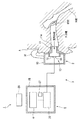
本実施形態の呼吸検査装置1は、図1に示すように、挿入部(装着部)11、検出部3及び本体部5を備えている。呼吸検査装置1は、挿入部11を介して被検者Aの耳内に装着される。検出部3は、呼吸に対応した生体信号を検出する振動センサ部(振動センサ)2を有する。本体部5は、検出部3により検出された生体信号に基づいて呼吸状態を測定する信号分析回路(測定手段)4を有する。
なお、本実施形態においては、被検者Aの耳内の呼吸に対応した空気振動を、上記生体信号として説明する。
An embodiment of a respiratory examination apparatus according to the present invention will be described with reference to FIGS.
As shown in FIG. 1, the respiratory examination apparatus 1 of the present embodiment includes an insertion part (mounting part) 11, a
In the present embodiment, air vibration corresponding to respiration in the ear of the subject A will be described as the biological signal.
上記振動センサ部3は、筐体10により箱状に形成されると共に、該筐体10の一端面には外耳道内に挿入可能な挿入部11が設けられている。即ち、振動センサ部3は、挿入部11を外耳道内に挿入することで、被検者Aの耳内に装着できるようになっている。また、挿入部11は、外耳道内に挿入されたときに、外耳道を密閉するようにゴム等の弾性材料により形成されると共に、先端に開口11aを有している。更に、筐体10は、外部からの音を遮断して該筐体10の内部に音を伝達しない材料により形成されている。
筐体10の内部には、耳内の空気振動を受信する受信手段12が設けられている。例えば、この受信手段12は、筐体10内部に設けられた薄膜13に水晶14を取り付けることにより構成される。水晶14は、耳内の空気振動により薄膜13が振動したときに、該薄膜13の振動状態に応じた電気信号(波形)を上記本体部5に送る機能を有している。これにより、振動センサ部3は、耳内の空気振動を検出することが可能である。
The
A receiving
なお、上記受信手段12は、上記構成に限られるものではない。例えば、図2に示すように構成することがより好ましい。即ち、筐体10内部の挿入部11側に、複数の微小な開口15aが形成された中間壁15を設けると共に、該中間壁15との間でV字状の空間を形成する斜壁部16を設ける。なお、該斜壁部16には、中間壁15と同様に複数の上記開口15aが形成されている。中間壁15と斜壁部16とで囲まれた空間内には、アルミニウム等の金属材料でV字状に形成された振動板17が配置されている。また、中間壁15及び斜壁部16の内側には、開口15aを覆うように音響抵抗18が配されている。また、筐体10の内部には、ロッド19を介して振動板17に接続するセラミックス素子20が取り付けられている。該セラミックス素子20は、例えば、ジルコン−チタン酸鉛系フェライト(PZT)等の圧電素子であり、バイモルフといわれる構造で曲げの応力に対して電荷を発生するようになっている。
こうすることで、受信手段12は、インピーダンスの低い空気の振動変化をより正確に捕らえて振動板17が振動し、該振動に応じた電気信号をセラミックス素子20が本体部5に送るようになっている。
The
By doing so, the receiving means 12 more accurately captures the vibration change of the low-impedance air, the
上記本体部5は、図1に示すように、筐体25により箱状に形成され、例えば、ベルト等により、被検者Aの腕等に装着できるようになっている。また、腕時計のように手首に装着できるように構成しても構わない。なお、本体部5は、振動センサ部2と電気的に接続されている。
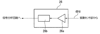
また、本体部5は、筐体25内に、信号検出回路26、信号分析回路4及びメモリ27を備えている。信号分析回路26は、上記受信手段12から送られてきた電気信号を検出する。信号分析回路4は、信号検出回路26から送られてきた電気信号に基づいて呼吸状態を測定する。メモリ27は、信号分析回路4により検出された呼吸状態を記録する。更に、筐体25の外表面には、メモリ27に記録されている各情報を表示する表示器28が設けられている。
As shown in FIG. 1, the main body 5 is formed in a box shape by a
Further, the main body 5 includes a
上記信号検出回路26は、図3に示すように、増幅部26aとローパスフィルタ26bとを有している。増幅部26aは、受信手段12から送られてきた電子信号を増幅する。
ローパスフィルタ26bは、例えば、心拍数に起因する電気信号を削除するもので、増幅部26aにより増幅された電気信号から、該電気信号に含まれる被検者Aの心拍等により生じた不要な信号を除去する。即ち、信号検出回路26及び上記振動センサ部3は、上記検出部3を構成している。
上記信号分析回路4は、信号検出回路26から送られてきた信号を解析して、呼吸状態の正常、異常を判断する。例えば、予め設定されている閾値等と比較し、信号レベルが閾値以上である場合には、呼吸状態が正常でない、例えば、無呼吸状態であると判断するようになっている。そして、信号分析回路4は、呼吸状態が正常でないと判断したときに、その旨を呼吸情報をメモリ27に送るようになっている。
As shown in FIG. 3, the
The low-
The
上記メモリ27は、タイマ機能を内蔵しており、上記信号分析回路4から送られてきた呼吸状態の情報を時間と合わせて記録できるようになっている
上記表示器28は、液晶モニタやLED等でメモリ27に記録された各情報を、図示しないスイッチにより任意に表示できるモニタとされている。なお、本実施形態においては、表示器28は、筐体25の外表面に設けた一体構成としたが、これに限られず、別個に設けても構わない。
The
このように構成された呼吸検査装置1により、被検者Aの呼吸状態を検出する場合について、以下に説明する。
まず、振動センサ部2及び本体部5を所定位置に装着する。装着後、被検者Aは、本体部5の図示しない電源スイッチを入れて就寝する。一方、耳内に装着された振動センサ部2は、被検者Aの呼吸に対応した耳内の空気振動、例えば、周波数0KHzから20KHz帯の空気振動を検出する。即ち、被検者Aが呼吸を行う毎に、骨や耳管等を介して音や圧力の変化が伝達され、外耳道内の空気が振動する。この空気振動は、挿入部11の開口11aから筐体10内に入り、受信手段12により受信される。また、受信手段12は、空気振動を検出すると、振動状態に応じた電気信号、例えば、図4に示すような波形の電気信号を信号検出回路26に送る。この際、信号検出回路26に送られてくる電気信号には、呼吸によって生じた電気信号とは別に、心拍等によって生じた電気信号等も含まれている。
The case where the respiratory state of the subject A is detected by the respiratory examination device 1 configured as described above will be described below.
First, the
信号検出回路26は、送られてきた電気信号を、図3に示すように、増幅部26aによって増幅する。その後、ローパスフィルタ26bによって上述した呼吸以外の要因、即ち、心拍等により生じた電気信号をカットする。これにより、信号検出回路26は、図5に示すように、呼吸に対応した電気信号を得ることができる。そして、信号検出回路26は、検出した電気信号を信号分析回路4に送る。
信号分析回路4は、送られてきた電気信号の信号レベルを、予め設定された閾値等と比較する。比較した結果、閾値以下である場合には、呼吸状態が正常であると判断する。また、閾値以上である場合には呼吸状態が異常、例えば、被検者Aが無呼吸状態等になったと判断して、その旨をメモリ27に知らせる。
メモリ27は、送られてきた呼吸状態の情報を、タイマ機能による時間と合わせて記録を随時記録する。
As shown in FIG. 3, the
The
The
呼吸検査装置1は、本体部5の電源が切られるまで上述したことを繰り返し、睡眠中の被検者Aの呼吸状態の検査を行う。
起床後、被検者Aは、表示器28のスイッチを操作してメモリ27に記録されている各情報、例えば、何時何分に呼吸状態の変化(無呼吸状態)があったことや、一晩に生じた呼吸異常の回数等を容易に確認することができる。
The respiratory examination apparatus 1 repeats the above until the main unit 5 is turned off, and examines the respiratory state of the subject A during sleep.
After getting up, the subject A operates the switch of the
上述した呼吸検査装置1によれば、振動センサ部2より耳内の呼吸に対応した空気振動の変化を検出でき、この空気振動に対応した生体信号に基づいて信号分析回路4が被検者Aの呼吸状態の測定を行う。このように、振動センサ部2を耳内に装着するだけで、容易に呼吸状態の検査を行うことができる。特に、耳内に振動センサ部2を装着して呼吸状態を検査できるので、被検者Aの拘束感を低減することができると共に、寝返り等により外れる可能性が低減する。また、周囲の温度や体動の影響を受け難くい状態で確実に呼吸状態を検出することができる。
更に、信号検出回路26は、ローパスフィルタ26bによって、心拍等により生じた不要な信号を除去するので、正確な呼吸情報を得ることができる。
According to the respiratory examination apparatus 1 described above, the
Furthermore, since the
なお、本発明の技術範囲は上記実施の形態に限定されるものではなく、本発明の趣旨を逸脱しない範囲において種々の変更を加えることが可能である。 The technical scope of the present invention is not limited to the above embodiment, and various modifications can be made without departing from the spirit of the present invention.
例えば、上記実施形態においては、耳内の空気振動(例えば、周波数0KHzから20KHz帯)を生体信号としたが、該生体信号は空気振動に限られるものではない。例えば、呼吸に対応した耳内の空気圧を生体信号としても構わない。この場合には、振動センサ部に変えて空気圧を検出する空気圧センサを耳内に装着すれば良い。また、呼吸に対応した耳内の音を生体信号としても構わない。この場合には、振動センサ部に変えて音を検出する音センサを耳内に装着すれば良い。特に、音センサによれば、周波数20Hzから20KHz帯の振動の検出に適している。更には、生体信号として、上述した各情報、即ち、呼吸に対応した空気圧や空気振動を組み合わせたものにしても構わない。この場合には、これらの異なる各情報を複数検出することができる複合センサを採用すれば良い。 For example, in the above-described embodiment, the air vibration in the ear (for example, the frequency of 0 KHz to 20 KHz band) is the biological signal, but the biological signal is not limited to the air vibration. For example, the air pressure in the ear corresponding to respiration may be used as the biological signal. In this case, an air pressure sensor that detects air pressure instead of the vibration sensor unit may be mounted in the ear. Moreover, the sound in the ear corresponding to respiration may be used as a biological signal. In this case, a sound sensor that detects sound instead of the vibration sensor unit may be mounted in the ear. In particular, the sound sensor is suitable for detecting vibrations in the frequency range of 20 Hz to 20 KHz. Furthermore, the biological information may be a combination of the above-described information, that is, air pressure or air vibration corresponding to respiration. In this case, a composite sensor that can detect a plurality of these different pieces of information may be employed.
また、振動センサ部に体動を検出する加速度センサを取り付けても構わない。この場合には、加速度センサは、受信手段に影響を与えないように、筐体の内側に直接取り付けるようにすることが好ましい。そして、加速度センサで検出した被検者Aの睡眠中の体動情報を信号検出回路に送り、ローパスフィルタ後の信号をさらに補正して体動の影響をなくすように構成すると良い。このように構成することで、さらに正確な被検者Aの呼吸状態の検査を行えることができる。 Moreover, you may attach the acceleration sensor which detects a body movement to a vibration sensor part. In this case, it is preferable that the acceleration sensor is directly attached to the inside of the housing so as not to affect the receiving means. And it is good to comprise so that the body movement information of the subject A in sleep detected by the acceleration sensor may be sent to the signal detection circuit, and the signal after the low-pass filter may be further corrected to eliminate the influence of the body movement. By comprising in this way, the test | inspection of the subject's A respiratory state can be performed more correctly.
また、振動センサ部は、被検者Aの片側の耳内だけに装着するだけでなく、両耳に装着することがより好ましい。こうすることで、例えば、睡眠中に被検者Aが寝返り等で横向きの体勢になったとしても、両耳で測定した生体信号の平均値を取ることができ、体勢の影響を受け難い。従って、呼吸状態の検査の正確性が向上する。 Moreover, it is more preferable that the vibration sensor unit is mounted not only in the ear on one side of the subject A but also in both ears. By doing so, for example, even if the subject A turns to a horizontal posture during sleep, for example, the average value of the biological signals measured by both ears can be taken and is not easily affected by the posture. Therefore, the accuracy of the examination of the respiratory state is improved.
1 呼吸検査装置
2 振動センサ部(振動センサ)
3 検出部
4 信号分析回路(測定手段)
11 挿入部(装着部)
1
3
11 Insertion part (mounting part)
Claims (6)
呼吸に対応した生体信号を検出するセンサを有する検出部と、
該検出部により検出された前記生体信号に基づいて呼吸状態を測定する測定手段とを備えることを特徴とする呼吸検査装置。 A mounting part for mounting in the ear;
A detection unit having a sensor for detecting a biological signal corresponding to respiration;
A respiratory examination apparatus comprising: a measuring unit that measures a respiratory state based on the biological signal detected by the detection unit.
前記センサが、耳内の振動を検出する振動センサであることを特徴とする呼吸検査装置。 The respiratory examination apparatus according to claim 1,
The respiratory test apparatus, wherein the sensor is a vibration sensor that detects vibration in an ear.
前記センサが、耳内の空気圧を検出する空気圧センサであることを特徴とする呼吸検査装置。 The respiratory examination apparatus according to claim 1,
The respiratory test apparatus, wherein the sensor is an air pressure sensor that detects an air pressure in an ear.
前記センサが、耳内の音を検出する音センサであることを特徴とする呼吸検査装置。 The respiratory examination apparatus according to claim 1,
A respiratory examination apparatus, wherein the sensor is a sound sensor that detects sound in an ear.
前記センサが、異なる複数の前記生体信号を検出する複合センサであることを特徴とする呼吸検査装置。 The respiratory examination apparatus according to claim 1,
The respiratory test apparatus, wherein the sensor is a composite sensor that detects a plurality of different biological signals.
前記検出部が、体動を検出する加速度センサを備え、
前記測定手段が、前記加速度センサにより検出された検出値に基づいて、呼吸状態の補正を行うことを特徴とする呼吸検査装置。 The respiratory examination apparatus according to any one of claims 1 to 5,
The detection unit includes an acceleration sensor for detecting body movement,
The respiratory examination apparatus, wherein the measuring unit corrects a respiratory state based on a detection value detected by the acceleration sensor.
Priority Applications (4)
| Application Number | Priority Date | Filing Date | Title |
|---|---|---|---|
| JP2003414746A JP2005168884A (en) | 2003-12-12 | 2003-12-12 | Respiration examination device |
| PCT/JP2004/014829 WO2005034750A1 (en) | 2003-10-07 | 2004-10-07 | Sleep aspiration state measurement device |
| EP04792127A EP1681018A1 (en) | 2003-10-07 | 2004-10-07 | Sleep aspiration state measurement device |
| US11/398,454 US20060270941A1 (en) | 2003-10-07 | 2006-04-05 | Device for measuring respiration during sleep |
Applications Claiming Priority (1)
| Application Number | Priority Date | Filing Date | Title |
|---|---|---|---|
| JP2003414746A JP2005168884A (en) | 2003-12-12 | 2003-12-12 | Respiration examination device |
Publications (2)
| Publication Number | Publication Date |
|---|---|
| JP2005168884A true JP2005168884A (en) | 2005-06-30 |
| JP2005168884A5 JP2005168884A5 (en) | 2007-02-01 |
Family
ID=34734455
Family Applications (1)
| Application Number | Title | Priority Date | Filing Date |
|---|---|---|---|
| JP2003414746A Pending JP2005168884A (en) | 2003-10-07 | 2003-12-12 | Respiration examination device |
Country Status (1)
| Country | Link |
|---|---|
| JP (1) | JP2005168884A (en) |
Cited By (7)
| Publication number | Priority date | Publication date | Assignee | Title |
|---|---|---|---|---|
| JP2008237847A (en) * | 2007-03-29 | 2008-10-09 | Toyo Univ | Biological information aquisition system |
| JP2009150565A (en) * | 2007-12-19 | 2009-07-09 | Mitsubishi Electric Corp | Air conditioner |
| JP2010022572A (en) * | 2008-07-18 | 2010-02-04 | Aloka Co Ltd | Biological information detection device |
| JP2012179398A (en) * | 2012-05-22 | 2012-09-20 | Hitachi Aloka Medical Ltd | Bioinformation detection device |
| WO2014021335A1 (en) | 2012-07-30 | 2014-02-06 | 株式会社三菱ケミカルホールディングス | Subject information detection unit, subject information processing device, electric toothbrush device, electric shaver device, subject information detection device, aging degree evaluation method, and aging degree evaluation device |
| JP2015024072A (en) * | 2013-07-29 | 2015-02-05 | ビフレステック株式会社 | Analyte information processor |
| JPWO2019230234A1 (en) * | 2018-05-28 | 2021-07-01 | 株式会社 資生堂 | Information processing equipment, programs, and sensing devices |
-
2003
- 2003-12-12 JP JP2003414746A patent/JP2005168884A/en active Pending
Cited By (8)
| Publication number | Priority date | Publication date | Assignee | Title |
|---|---|---|---|---|
| JP2008237847A (en) * | 2007-03-29 | 2008-10-09 | Toyo Univ | Biological information aquisition system |
| JP2009150565A (en) * | 2007-12-19 | 2009-07-09 | Mitsubishi Electric Corp | Air conditioner |
| JP2010022572A (en) * | 2008-07-18 | 2010-02-04 | Aloka Co Ltd | Biological information detection device |
| JP2012179398A (en) * | 2012-05-22 | 2012-09-20 | Hitachi Aloka Medical Ltd | Bioinformation detection device |
| WO2014021335A1 (en) | 2012-07-30 | 2014-02-06 | 株式会社三菱ケミカルホールディングス | Subject information detection unit, subject information processing device, electric toothbrush device, electric shaver device, subject information detection device, aging degree evaluation method, and aging degree evaluation device |
| JP2015024072A (en) * | 2013-07-29 | 2015-02-05 | ビフレステック株式会社 | Analyte information processor |
| JPWO2019230234A1 (en) * | 2018-05-28 | 2021-07-01 | 株式会社 資生堂 | Information processing equipment, programs, and sensing devices |
| JP7216084B2 (en) | 2018-05-28 | 2023-01-31 | 株式会社 資生堂 | Information processing device, program, and sensing device |
Similar Documents
| Publication | Publication Date | Title |
|---|---|---|
| US20060270941A1 (en) | Device for measuring respiration during sleep | |
| US20180338743A1 (en) | Acoustic detection mask systems and/or methods | |
| JP5808909B2 (en) | Passive monitoring sensor system using mattress | |
| JP5055502B2 (en) | Biopsy device | |
| JPH10155755A (en) | Medical apparatus | |
| JP2007202939A (en) | Biological information detecting apparatus | |
| US20060212273A1 (en) | Real-time snoring assessment apparatus and method | |
| EP1879501A2 (en) | Cough detector | |
| US9820694B2 (en) | Devices for diagnosing sleep apnea or other conditions and related systems and methods | |
| US20170035350A1 (en) | System and method for detecting bruxism | |
| JP4253568B2 (en) | Respiratory data collection system | |
| JP2011004968A (en) | Deglutition activity monitoring device, deglutition activity monitoring system, biological information recording device and deglutition activity monitoring program | |
| KR102220150B1 (en) | Respiratory sensing device and respiratory monitoring system | |
| JP2005168884A (en) | Respiration examination device | |
| JP2008110138A (en) | Breathing program, recording medium, and apparatus for breath determination | |
| WO2012165427A1 (en) | Respiration detection device | |
| KR101871285B1 (en) | Respiratory sensing device and respiratory monitoring system | |
| KR101726235B1 (en) | Ear-insertion Type Health Monitoring Device with Piezo Sensor | |
| GB2214302A (en) | An apnoea monitor for use during sleep | |
| JP6896209B2 (en) | Swallowing function measurement system | |
| JPWO2008152989A1 (en) | Respiratory state detection system, program, and recording medium | |
| WO2007144626A1 (en) | Breathing monitor apparatus | |
| KR101999359B1 (en) | Respiratory sensing device and respiratory monitoring system | |
| WO2009103111A1 (en) | Patient's breathing detection and monitoring | |
| KR20080068483A (en) | Sleep monitoring device |
Legal Events
| Date | Code | Title | Description |
|---|---|---|---|
| A521 | Written amendment |
Free format text: JAPANESE INTERMEDIATE CODE: A523 Effective date: 20061211 |
|
| A621 | Written request for application examination |
Free format text: JAPANESE INTERMEDIATE CODE: A621 Effective date: 20061211 |
|
| A521 | Written amendment |
Free format text: JAPANESE INTERMEDIATE CODE: A821 Effective date: 20061212 |
|
| A131 | Notification of reasons for refusal |
Free format text: JAPANESE INTERMEDIATE CODE: A131 Effective date: 20091104 |
|
| A02 | Decision of refusal |
Free format text: JAPANESE INTERMEDIATE CODE: A02 Effective date: 20100302 |