JP2005166375A - Battery pack - Google Patents
Battery pack Download PDFInfo
- Publication number
- JP2005166375A JP2005166375A JP2003402174A JP2003402174A JP2005166375A JP 2005166375 A JP2005166375 A JP 2005166375A JP 2003402174 A JP2003402174 A JP 2003402174A JP 2003402174 A JP2003402174 A JP 2003402174A JP 2005166375 A JP2005166375 A JP 2005166375A
- Authority
- JP
- Japan
- Prior art keywords
- battery
- battery pack
- covering material
- thermal
- control board
- Prior art date
- Legal status (The legal status is an assumption and is not a legal conclusion. Google has not performed a legal analysis and makes no representation as to the accuracy of the status listed.)
- Pending
Links
- 239000000463 material Substances 0.000 claims abstract description 21
- WABPQHHGFIMREM-UHFFFAOYSA-N lead(0) Chemical compound [Pb] WABPQHHGFIMREM-UHFFFAOYSA-N 0.000 claims abstract description 13
- 239000002648 laminated material Substances 0.000 claims description 5
- 238000009826 distribution Methods 0.000 claims description 4
- 238000004519 manufacturing process Methods 0.000 abstract description 7
- 238000010030 laminating Methods 0.000 abstract 1
- 239000000758 substrate Substances 0.000 abstract 1
- 229920001296 polysiloxane Polymers 0.000 description 6
- 238000001514 detection method Methods 0.000 description 3
- 238000010586 diagram Methods 0.000 description 3
- 230000005669 field effect Effects 0.000 description 2
- 238000009434 installation Methods 0.000 description 2
- 229920002050 silicone resin Polymers 0.000 description 2
- 229910000679 solder Inorganic materials 0.000 description 2
- 238000005476 soldering Methods 0.000 description 2
- HBBGRARXTFLTSG-UHFFFAOYSA-N Lithium ion Chemical compound [Li+] HBBGRARXTFLTSG-UHFFFAOYSA-N 0.000 description 1
- 230000007175 bidirectional communication Effects 0.000 description 1
- 238000009529 body temperature measurement Methods 0.000 description 1
- OJIJEKBXJYRIBZ-UHFFFAOYSA-N cadmium nickel Chemical compound [Ni].[Cd] OJIJEKBXJYRIBZ-UHFFFAOYSA-N 0.000 description 1
- 239000011248 coating agent Substances 0.000 description 1
- 238000000576 coating method Methods 0.000 description 1
- 230000006854 communication Effects 0.000 description 1
- 238000005520 cutting process Methods 0.000 description 1
- 238000013500 data storage Methods 0.000 description 1
- 238000007599 discharging Methods 0.000 description 1
- 230000000694 effects Effects 0.000 description 1
- 229910001416 lithium ion Inorganic materials 0.000 description 1
- 238000007726 management method Methods 0.000 description 1
- 238000000034 method Methods 0.000 description 1
- 238000003860 storage Methods 0.000 description 1
Images
Classifications
-
- Y—GENERAL TAGGING OF NEW TECHNOLOGICAL DEVELOPMENTS; GENERAL TAGGING OF CROSS-SECTIONAL TECHNOLOGIES SPANNING OVER SEVERAL SECTIONS OF THE IPC; TECHNICAL SUBJECTS COVERED BY FORMER USPC CROSS-REFERENCE ART COLLECTIONS [XRACs] AND DIGESTS
- Y02—TECHNOLOGIES OR APPLICATIONS FOR MITIGATION OR ADAPTATION AGAINST CLIMATE CHANGE
- Y02E—REDUCTION OF GREENHOUSE GAS [GHG] EMISSIONS, RELATED TO ENERGY GENERATION, TRANSMISSION OR DISTRIBUTION
- Y02E60/00—Enabling technologies; Technologies with a potential or indirect contribution to GHG emissions mitigation
- Y02E60/10—Energy storage using batteries
Landscapes
- Secondary Cells (AREA)
- Battery Mounting, Suspending (AREA)
Abstract
Description
本発明は、サーミスタ等の感熱素子を備えたパック電池に関する。 The present invention relates to a battery pack provided with a thermal element such as a thermistor.
ノートPC等の携帯型電子機器には、繰り返し充放電可能な二次電池を素電池として内蔵するパック電池がその電源として利用されている。パック電池には、素電池の他に、携帯型電子機器と素電池との間で電力流通制御が行われる制御回路を形成している制御基板、さらには電池温度の感知用感熱素子として複数個(例えば2個)のサーミスタが内蔵されている。複数個のサーミスタは素電池の外装缶に熱接触するように別々に配されており、各サーミスタは2本のリード線で制御基板に接続されている。そして、一方のサーミスタによる素電池の温度情報は、制御回路に入力され、これを受けた制御回路は電池に対する過充電・過放電の防止を図る。もう一方のサーミスタによる電池の温度情報は、PCなどの機器に出力される(例えば、特許文献1、2)。
In portable electronic devices such as notebook PCs, a pack battery that incorporates a rechargeable secondary battery as a unit cell is used as a power source. In addition to the unit cell, the battery pack includes a control board that forms a control circuit that controls power distribution between the portable electronic device and the unit cell, and a plurality of thermosensitive elements for sensing the battery temperature. (For example, two) thermistors are incorporated. The plurality of thermistors are separately arranged so as to be in thermal contact with the outer can of the unit cell, and each thermistor is connected to the control board by two lead wires. Then, the temperature information of the unit cell by one thermistor is input to the control circuit, and the control circuit that receives this information prevents overcharge / overdischarge of the battery. The temperature information of the battery by the other thermistor is output to a device such as a PC (for example,
このように、温度情報の出力先の数に応じたサーミスタを備えるのは、1個のサーミスタから複数の出力先に温度情報を出力することがその特性上困難なためである。
しかしながら、上記従来技術では各サーミスタのリード線を制御基板に個別に接続するため、計4本のリード線の接続作業が必要になる。一般に、N個の感熱素子を制御基板に接続しようとする場合には、少なくとも2N本のリード線を制御基板の導電ランドにハンダ付けする必要があり、その分、作業工数が増大する。
また近年のように、パック電池自体が縮小化・軽量化の傾向にあると感熱素子の設置スペースの縮小化が要求され、設置自体の難化に繋がることとなる。
However, in the above prior art, since the lead wires of each thermistor are individually connected to the control board, it is necessary to connect a total of four lead wires. In general, when N thermal elements are to be connected to the control board, it is necessary to solder at least 2N lead wires to the conductive land of the control board, which increases the number of work steps.
Further, as in recent years, when the battery pack itself tends to be reduced in size and weight, a reduction in the installation space for the thermal element is required, which leads to difficulty in installation.
加えて、N個の感熱素子はディスクリートな部品であるので、それらを電池の外装缶にシリコーン樹脂で取り付ける場合には、シリコーン樹脂使用量を均一化させることが困難であり、そのため熱感知性能の面でばらつきを生じる原因ともなる。
本発明は、上記課題に鑑みなされたものであって、複数の感熱素子を備えたパック電池において製造作業を簡素化し、低コストなパック電池を提供することを目的とする。
In addition, since the N heat sensitive elements are discrete components, it is difficult to equalize the amount of silicone resin used when attaching them to the battery outer can with silicone resin. This also causes variations in the surface.
The present invention has been made in view of the above problems, and it is an object of the present invention to simplify a manufacturing operation and provide a low-cost pack battery in a pack battery including a plurality of thermal elements.
上記課題を解決するために、本発明は以下の構成を採る。
N個の感熱素子を別々にパック電池内に配するのではなく、N個の感熱素子をラミネートなどの被覆材を用いて一体的に覆う。ただし、当該被覆材部分内において、各感熱素子の第1の電極同士を共通電極として互いに接続する。
そして、この共通端子からリード線が被覆材外部へ延出されており、さらに各感熱素子の第2の電極から、独立したN本のリード線も被覆材外部に延出されており、これら計(N+1)本のリード線を制御基板に接続し、当該被覆材部分を電池に熱接触するように配する。
In order to solve the above problems, the present invention adopts the following configuration.
Rather than separately arranging the N thermal elements in the battery pack, the N thermal elements are integrally covered with a covering material such as a laminate. However, in the said coating | coated material part, 1st electrodes of each thermosensitive element are mutually connected as a common electrode.
A lead wire extends from the common terminal to the outside of the covering material, and N independent lead wires extend from the second electrode of each thermal element to the outside of the covering material. (N + 1) lead wires are connected to the control board, and the covering material portion is arranged so as to be in thermal contact with the battery.
このパック電池によれば、製造する時に、感熱素子を取り付ける工程において、素電池と電池装着対象機器との間における電力流通を制御する制御基板等との接続に係る工数が、上述した従来技術と比べて(N−1)回分少なくなるので、作業面ひいてはコスト面で優位性を有する。
上記パック電池において、各感熱素子における共通電極からの第1のリードの延出部を制御基板を介してGROUND接続する構成とすると、制御基板へ装着するリード線の数が低減されるので、回路の簡略化にも繋がる。
According to this battery pack, in the process of attaching the thermal element at the time of manufacture, the man-hours related to the connection with the control board or the like that controls the power distribution between the unit cell and the battery mounting target device are the same as the prior art described above. Since it is reduced by (N-1) times as compared with this, it has an advantage in terms of work and cost.
In the battery pack described above, when the extended portion of the first lead from the common electrode in each thermal element is configured to be GROUND connected via the control board, the number of lead wires attached to the control board is reduced. It also leads to simplification.
なお、本発明においては、N個の感熱素子が被覆材によって一体化されたもの(以下、「感熱素子ユニット」という)をあらかじめ作成しておく必要があるが、上記のように、手作業による細かな接続の回数を減らすことができるため、パック電池の製造工程全体としても簡略化に効果がある。
これらのことから、本発明に関するパック電池では、従来と同様に複数のサーミスタなどの感熱素子から別々にデータ出力をするので、電池対象機器が少なくとも1個の感熱素子からの温度情報を取得することができるとともに、製造時間やコスト面での優位性を有するものとなる。
In the present invention, it is necessary to prepare in advance an N heat-sensitive elements integrated with a covering material (hereinafter referred to as a “heat-sensitive element unit”). Since the number of fine connections can be reduced, the entire manufacturing process of the battery pack is effective for simplification.
For these reasons, the battery pack according to the present invention outputs data separately from the thermal elements such as a plurality of thermistors as in the prior art, so that the battery target device acquires temperature information from at least one thermal element. In addition, it has advantages in terms of manufacturing time and cost.
さらに上記パック電池によれば、N個の感熱素子が1つの感熱素子ユニットに含まれているので、N個の感熱素子からのばらつきが無くなる。 Furthermore, according to the battery pack, since N thermal elements are included in one thermal element unit, variations from the N thermal elements are eliminated.
(パック電池10の全体構成)
以下では、図1を用いて、本発明の一適用例であるパック電池の全体構成について説明する。
(Overall configuration of the battery pack 10)
Below, the whole structure of the pack battery which is one application example of this invention is demonstrated using FIG.
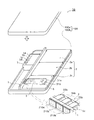
まず、パック電池10は、PC(Personal Computer)用のものであって、制御基板1と3個の素電池2a、2b、2cで構成された電池2とが、上側ケース100aと下側ケース100bとで形成される内部空間に収納された構成を有している。
制御基板1には、両主表面に配線パターン(不図示)が形成されており、感熱素子ユニット3を含む複数の電子部品が、この配線パターンにおける所定箇所の導電ランドに各々ハンダ付けにより実装されている。なお、感熱素子ユニット3のリード線延出部は、導電ランド210a、210b、210cに接続されている。また、制御基板1の片側の主表面に、外部接続コネクタ5が装着されており、外部接続コネクタ5の一面が下側ケース100bの側面に開けられた窓部から外側に露出するようになっている。
First, the
On the
上記外部コネクタ5には、PC本体へ電力を出力する端子5a、PC本体への通信端子5b、PC本体が電池2の温度を読みとる端子5c、パック電池10のGROUND端子5dが装備されている。そして、感熱素子ユニット3は電池2の外装缶の主表面に熱接触するように配設された状態で載置されている。
N=2個の場合の例として、サーミスタ31a、31bを有する感熱素子ユニット3は、その温度検知機能部分となるサーミスタ31a、31bが素電池2cに近接配置となるように、かつシリコーン6を介して素電池2cに熱接触するように配されており、素電池2cで生じた熱が伝達されるようになっている。素電池2a、2b、2cは角形の外観形状を有しており、その配置の関係から便宜上、それぞれ図1に示すように直列に接続されている。図1においては、説明の便宜上、感熱素子ユニット3は誇張して描かれている。
(感熱素子ユニット3の構成及び装着作業)
感熱素子ユニット3の構成については、図3を用いて、また感熱素子ユニットの装着作業については図4、図5も併用して説明する。
The
As an example in the case of N = 2, the
(Configuration and mounting work of thermal element unit 3)
The configuration of the
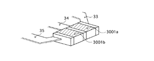
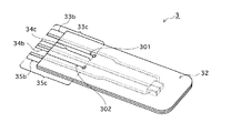
この感熱素子ユニット3は、2個のサーミスタ31a、31bと3つのリード33、34、35(それぞれ図3における斜線部分)、そしてそれらを覆う被覆材によって構成されている。被覆材としては、ラミネート材32a、32bを用いている。
サーミスタ31aはその一面がリード線33の基端部33aと接合され、その反対面がリード線34の基端部34aと接合されている。同様に、サーミスタ31bの一面がリード線34の基端部34bと接合し、その反対面がリード線35の基端部35aと接合している。リード線34はサーミスタ31aと31bの一方の電極に共通に接続された共通端子とされている。2個のサーミスタ31a、31bと3本のリード線33、34、35の基端部分は、ラミネート材32aと32bで挟み込むようにして一体的に覆われている。
The
One surface of the
なお、ラミネート材32aと32bにはそれぞれスリット301a、302aと301b、302bを有している。
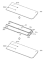
次に、図4、図5を用いて感熱素子ユニット3の装着作業について説明する。
図4に示すように、接合されたサーミスタ31aの一面3001a(斜線部分)とサーミスタ31bの一面3001b(斜線部分)、もしくはそれらの反対の面が、電池2の温度感知部分である。つまり、これら2つの面3001a、3001b、もしくはその反対の面が電池2の外装缶と平行になるように、感熱素子ユニット3は電池2に熱接触するように配される。
The
Next, the mounting operation of the
As shown in FIG. 4, one
なお、制御基板1をケース100bに装着する前に、被覆材部分32からの延出部33b、34b、35bを制御基板1の導電ランド210a、210c、210bにそれぞれハンダ付けする必要がある。そして、制御基板1をケース100bに装着した後にシリコーンで感熱素子ユニット3と電池2を熱接触させる。
(パック電池10の回路構成)
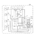
不図示の配線パターンについては、図2のブロック回路図に基づいて各電子部品関連の接続がなされるように施されている。
Before mounting the
(Circuit configuration of the battery pack 10)
A wiring pattern (not shown) is provided so that connection related to each electronic component is made based on the block circuit diagram of FIG.
まず、感熱素子ユニット3に備えられているサーミスタ31aの温度情報を出力する端子は、パック電池10の機能を主にコントロールするためのメインのIC(以下、「MCU」という。)12に導電ランド210aを介して接続されている。また、サーミスタ31bの温度情報を出力する端子は、導電ランド210bを介して制御基板1からPC本体がパック電池10内の電池2の温度を読みとるための出力端子5cに接続されている。共通端子34は、導電ランド210cを介して感熱素子ユニット3のGROUND端子として出力端子5dに接続されている。
First, a terminal for outputting temperature information of the
他にも、パック電池の設定値や電池の残容量などのデータを格納し、MCU12により制御されている素子13や、様々な保護素子が装備された保護回路200や、パック電池内の回路を流れる電流値を読みとるための抵抗22が設置されている。MCU12もPC本体との双方向の通信用出力端子5bを介して、電池の温度情報の出力も受け取りながら、パック電池全体を適切にコントロールしている。また、保護回路200は、電池2の両端電圧を検出して過電圧・過放電を監視したり、抵抗22の両端の値を検出して過電流を監視する素子14や、設定温度を超える温度上昇により温度ヒューズを自ら溶接する電界効果トランジスタ(以下、「FET」と呼ぶ)15、温度または電流で溶断する保護素子16、そして充放電をコントロールするFET17で構成されている。こうした各素子を装備していることにより、保護回路200は、サーミスタ31aからの出力信号で電池温度を知ることができるので、電池2の温度が設定温度よりも高くなった場合に、電池2の電流を遮断したり、電池2が過充電・過放電状態になる前に、PCと電池2での電力流通を遮断する指示信号、さらには外部端子のショート等により過電流が流れた場合にも、PCと電池2での電力流通を遮断する指示信号をFET17に出力する。同時に、サーミスタ31bからの出力信号でPC本体にも電池の温度情報が伝えられ、その情報を基にしてPC本体やPCユーザーによるデータ把握・管理に役立てられている。
(パック電池の優位性)
上記のように、感熱素子ユニット3においては、サーミスタ31aと31bの共通端子がGROUND接続されていることにより、被覆材部分32からの延出部の数が1本(一般的には(N−1)本)減少しているので、制御基板1に形成されている配線パターンにおける導電ランドへのハンダ付け作業量を低減することができる。同様に、感熱素子ユニット3を電池2cにシリコーン6で熱接触するように配設させることによって、シリコーン6によってサーミスタ31a、31bの2個を熱接触するように配設させる場合と比べて作業量の低減にも繋がると共に、電池2における最適かつ同一箇所の温度を測定することができ、2個のサーミスタ31a、31bによる温度検知のばらつきを低減させることができるという利点もある。
In addition, data such as the set value of the battery pack and the remaining capacity of the battery is stored, and the
(Advantages of battery pack)
As described above, in the
そして、感熱素子ユニット3を、1箇所のみのシリコーン使用で電池2の外装缶に熱接触するように配設可能である。そのため、従来のように2個のサーミスタ31a、31bを取り付ける場合と比較して、シリコーン6の不均一性による温度検知のばらつきを低減させることができるという利点もある。
また、ラミネート材32a、32bのスリット301a、302aと301b、302bにより被覆材部分32にスリット301と302が形成されるので、リード線33、34、35における可動部33c、34c、35cが形成される。その結果、制御基板1に感熱素子ユニット3の出力部33b、34b、35bを導電ランドに接合するときに、接合可能な範囲が大きく拡大されるという効果を奏する。
The
Further, since the
これらのことから、パック電池10において、感熱素子ユニット3は2個のサーミスタによる温度情報の精度の向上に寄与し、同じ温度情報数を出力しつつ、製造工程でのコストの優位性を有することとなる。
なお、上記ではN=2個の場合での説明だが、1つのパック電池10内における温度計測点数が多いほど、つまりサーミスタの数Nが多いほど、GROUND端子の共通化により感熱素子ユニット3からの出力端子に用いるリード線の数を減少させることができるために、上記内容について効果が増大する。
(その他の事項)
なお、本発明において、感熱素子としてサーミスタ以外でもPTC、NTC、ブレーカ、ヒューズなどもパック電池10の構造に適用でき、またその数も2個だけではなく様々な数でも適用できる。また、電池の種類としてはリチウムイオン電池以外にニッケルカドミウム蓄電池などでも適用可能であるし、その電池の数も3個に限定されず、例えば2個でも、4個以上でもパック電池10の構造に適用できる。さらに、素電池の接続についても直列に限定されずにパック電池10に適用できる。
For these reasons, in the
In the above description, N = 2. However, as the number of temperature measurement points in one
(Other matters)
In the present invention, PTC, NTC, breaker, fuse, etc. can be applied to the structure of the
本発明は、パック電池内における回路の簡略化や製造コストの削減に繋げつつも、縮小・軽量化されているパック電池において、複数の感熱素子によるデータを有することで、二次電池の正確な温度表示、かつ二次電池使用機器への適切な電力流通に大変有効となるものである。 The present invention has the data of a plurality of thermal elements in a pack battery which is reduced in size and weight while reducing the circuit in the battery pack and reducing the manufacturing cost. This is very effective for temperature display and for proper power distribution to devices using secondary batteries.
1:制御基板
2:電池
3:感熱素子ユニット
5:外部コネクタ
5a:電力供給出力端子
5b:データ出力端子
5c:温度情報出力端子
5d:GROUND端子
12:パック電池のメインIC
13:容量等のデータ格納素子
15:電界効果トランジスタ
32:被覆材
33、34、35:リード線
1: control board 2: battery 3: thermal element unit 5:
13:
Claims (5)
前記N個の感熱素子は、被覆材によって一体的に覆われており、
且つ前記被覆材の中において、前記各感熱素子の第1の電極同士が共通電極として互いに接続されているとともに、この共通電極から第1のリード線が前記被覆材の外部へ延出されており、
さらに前記各感熱素子の第2の電極から、独立したN本の第2のリード線が前記被覆材の外部に延出されており、
前記第1のリード線及び第2のリード線の延出部分が前記制御基板に接続されている
ことを特徴とするパック電池。 A unit cell, a control board for controlling power distribution between the unit cell and the battery mounting target device, and N heat sensors (N is an integer of 2 or more) arranged to be in thermal contact with the unit cell. A battery pack having an element,
The N thermal elements are integrally covered with a covering material,
In the covering material, the first electrodes of the thermal elements are connected to each other as a common electrode, and a first lead wire extends from the common electrode to the outside of the covering material. ,
Furthermore, N second lead wires independent from the second electrode of each of the thermal elements are extended to the outside of the covering material,
An extended portion of the first lead wire and the second lead wire is connected to the control board.
ことを特徴とする請求項1に記載のパック電池。 The battery pack according to claim 1, wherein the thermal element is a thermistor.
ことを特徴とする請求項1に記載のパック電池。 The battery pack according to claim 1, wherein the covering material is a laminate material.
ことを特徴とする請求項1に記載のパック電池。 2. The battery pack according to claim 1, wherein the extension portion of the first lead wire is GROUND-connected through the control board in a state of being attached to the battery attachment target device.
前記外部端子に前記N個の感熱素子の少なくとも1個が接続されている
ことを特徴とする請求項1〜4のいずれかに記載のパック電池。 It has an external terminal for connecting to the battery mounting target device,
The battery pack according to any one of claims 1 to 4, wherein at least one of the N heat sensitive elements is connected to the external terminal.
Priority Applications (1)
| Application Number | Priority Date | Filing Date | Title |
|---|---|---|---|
| JP2003402174A JP2005166375A (en) | 2003-12-01 | 2003-12-01 | Battery pack |
Applications Claiming Priority (1)
| Application Number | Priority Date | Filing Date | Title |
|---|---|---|---|
| JP2003402174A JP2005166375A (en) | 2003-12-01 | 2003-12-01 | Battery pack |
Publications (1)
| Publication Number | Publication Date |
|---|---|
| JP2005166375A true JP2005166375A (en) | 2005-06-23 |
Family
ID=34725851
Family Applications (1)
| Application Number | Title | Priority Date | Filing Date |
|---|---|---|---|
| JP2003402174A Pending JP2005166375A (en) | 2003-12-01 | 2003-12-01 | Battery pack |
Country Status (1)
| Country | Link |
|---|---|
| JP (1) | JP2005166375A (en) |
Cited By (1)
| Publication number | Priority date | Publication date | Assignee | Title |
|---|---|---|---|---|
| JP2012182133A (en) * | 2011-03-02 | 2012-09-20 | Samsung Sdi Co Ltd | Battery pack |
-
2003
- 2003-12-01 JP JP2003402174A patent/JP2005166375A/en active Pending
Cited By (2)
| Publication number | Priority date | Publication date | Assignee | Title |
|---|---|---|---|---|
| JP2012182133A (en) * | 2011-03-02 | 2012-09-20 | Samsung Sdi Co Ltd | Battery pack |
| US9269946B2 (en) | 2011-03-02 | 2016-02-23 | Samsung Sdi Co., Ltd. | Battery pack having protection circuit module |
Similar Documents
| Publication | Publication Date | Title |
|---|---|---|
| US11050096B2 (en) | Battery protection circuit and battery pack including same | |
| EP0629017B1 (en) | Improvements in or relating to battery pack arrangements | |
| JP4882235B2 (en) | Battery protection module | |
| US9876377B2 (en) | Multichip, battery protection apparatus, and battery pack | |
| US7638977B2 (en) | Battery pack protective circuit for detecting overcharge or wire disconnect | |
| CN104167572B (en) | Battery pack | |
| KR101382942B1 (en) | Protection element, battery control device, and battery pack | |
| CN103840228B (en) | Battery | |
| KR101193173B1 (en) | Circuit module and battery pack including the same | |
| KR102505615B1 (en) | Battery pack | |
| EP3644473B1 (en) | Battery protection circuit and battery pack comprising same | |
| KR100782101B1 (en) | Protective circuit and battery pack including same | |
| KR102512068B1 (en) | Battery module with thermocouple unit | |
| US12062933B2 (en) | Battery protection circuit and battery pack including same | |
| KR20190032882A (en) | Battery protection circuit | |
| US9893519B1 (en) | Substrate providing electrical communication between power sources | |
| JP2005166375A (en) | Battery pack | |
| JP2003346920A (en) | Battery overheating detecting device and battery pack including the same | |
| JP2004087851A (en) | Circuit board and battery pack | |
| KR20180049456A (en) | Battery proction circuit using a currnt sensing resistor | |
| KR20150005288A (en) | Battery pack and Protective circuit module applied for the same | |
| JP2009076231A (en) | Battery pack | |
| JP2012043710A (en) | Secondary battery device | |
| KR101746729B1 (en) | apparatus for protecting battery charge/discharge with non wire cross | |
| KR20220037793A (en) | Battery protection circuit and battery pack including same |
Legal Events
| Date | Code | Title | Description |
|---|---|---|---|
| A621 | Written request for application examination |
Free format text: JAPANESE INTERMEDIATE CODE: A621 Effective date: 20051011 |
|
| A131 | Notification of reasons for refusal |
Free format text: JAPANESE INTERMEDIATE CODE: A131 Effective date: 20090428 |
|
| A02 | Decision of refusal |
Free format text: JAPANESE INTERMEDIATE CODE: A02 Effective date: 20090908 |