JP2005166330A - Terminal caulking device and terminal caulking method - Google Patents
Terminal caulking device and terminal caulking method Download PDFInfo
- Publication number
- JP2005166330A JP2005166330A JP2003401164A JP2003401164A JP2005166330A JP 2005166330 A JP2005166330 A JP 2005166330A JP 2003401164 A JP2003401164 A JP 2003401164A JP 2003401164 A JP2003401164 A JP 2003401164A JP 2005166330 A JP2005166330 A JP 2005166330A
- Authority
- JP
- Japan
- Prior art keywords
- terminal
- temperature
- electrode
- caulking
- thickness
- Prior art date
- Legal status (The legal status is an assumption and is not a legal conclusion. Google has not performed a legal analysis and makes no representation as to the accuracy of the status listed.)
- Granted
Links
Images

Landscapes
- Manufacturing Of Electrical Connectors (AREA)
Abstract
【課題】 電極部の温度を測定して、電極部を目標温度まで上昇させることにより、電線の絶縁被膜を確実に溶かして接続端子に電線を接続することができる端子かしめ装置および端子かしめ方法を提供すること。
【解決手段】 端子かしめ装置1では、赤外線温度センサ54により端子45の温度が測定され、コントローラ5によりその測定温度がかしめ端子温度TP2(500℃)に達したときに、電極38,39に対する通電が終了する。また、通電終了後に、電磁スケール51および電磁センサ53により端子45の厚さが測定され、コントローラ5によりその厚さが所定厚LF(3.60mm)以下になったときに、端子45に対する加圧が終了する。
【選択図】 図1
PROBLEM TO BE SOLVED: To provide a terminal caulking device and a terminal caulking method capable of reliably melting an insulating film of an electric wire and connecting the electric wire to a connection terminal by measuring the temperature of the electrode portion and raising the electrode portion to a target temperature. To provide.
In a terminal caulking device 1, the temperature of a terminal 45 is measured by an infrared temperature sensor 54. When the measured temperature reaches a caulking terminal temperature TP2 (500 ° C.) by a controller 5, energization to electrodes 38 and 39 is performed. Ends. Further, after energization is completed, the thickness of the terminal 45 is measured by the electromagnetic scale 51 and the electromagnetic sensor 53, and when the thickness becomes equal to or less than the predetermined thickness LF (3.60 mm) by the controller 5, the pressure applied to the terminal 45 is increased. Ends.
[Selection] Figure 1
Description
本発明は、接続端子に電線を挿入した状態で通電加熱して接続端子を押し潰すことにより、接続端子に電線をかしめる通電かしめを行う装置および方法に関する。より詳細には、電線の絶縁被膜を確実に溶かして接続端子に電線を接続することができる端子かしめ装置および端子かしめ方法に関するものである。 The present invention relates to an apparatus and method for energizing and caulking an electric wire to a connection terminal by energizing and heating the connection terminal while the electric wire is inserted into the connection terminal to crush the connection terminal. More specifically, the present invention relates to a terminal caulking device and a terminal caulking method that can reliably melt an insulating coating of an electric wire and connect the electric wire to a connection terminal.
エナメル等の絶縁被膜が施された電線を束ねて、そこに接続端子をかしめる場合には、電極を通電加熱して接続端子を押し潰すことにより接続端子に電線をかしめる通電かしめが行われている。この通電かしめの方法の1つとして、例えば、特開2002−224841号公報に開示されたものがある。 When bundling an electric wire with an insulating coating such as enamel and caulking the connection terminal there, energizing and caulking the electric wire to the connection terminal is performed by energizing and heating the electrode and crushing the connection terminal. ing. As one of the energization caulking methods, for example, there is one disclosed in JP-A-2002-224841.
この方法は、接続端子の円筒状の接続部に絶縁被膜で被覆した電線を挿入する挿入工程と、接続部に電線を密着させるために、接続部を押し潰す予備圧潰工程と、接続部に電線を接続するために、接続部及び電線を通電加熱しつつ押し潰して絶縁被膜を溶解又は剥離する通電加熱・加圧工程とからなることを特徴とする。 This method includes an insertion step of inserting an electric wire covered with an insulating film into a cylindrical connection portion of a connection terminal, a preliminary crushing step of crushing the connection portion in order to bring the electric wire into close contact with the connection portion, and an electric wire in the connection portion. In order to connect, the connection part and the electric wire are energized and heated, and the process is characterized by comprising an energizing heating / pressurizing step of crushing and melting or peeling off the insulating coating.
これにより、この方法では、接続部を予備的に押し潰して接続部に電線を密着させ、その後、接続部及び電線を通電加熱しつつ押し潰して絶縁被膜を溶解又は剥離することで、電線の中央部までムラなく発熱させ、十分に絶縁被膜を溶かして接続部に電線を接続し、接続部の品質の安定化を図るようになっている。
しかしながら、上記した特開2002−224841号公報に開示された方法では、かしめ時における電極部(電極または接続端子)の温度については何等制御されていない。つまり、電極部の温度が安定して上昇していることを確認することができない。そのため、端子かしめ中に所定の通電電流を印加する場合には、環境温度の違いあるいは電極の劣化などによる抵抗値の変化などによって、かしめ時における電極部の最高温度が異なってしまう。このため、電線の絶縁被膜が完全に溶けないおそれがある。すなわち、通電が正常であっても、環境の変化や電極の劣化などによる抵抗値の変化などによって、電極の温度が目標温度まで上昇しないおそれがある。 However, in the method disclosed in Japanese Patent Application Laid-Open No. 2002-224841, the temperature of the electrode portion (electrode or connection terminal) at the time of caulking is not controlled at all. That is, it cannot be confirmed that the temperature of the electrode portion has risen stably. For this reason, when a predetermined energization current is applied during terminal caulking, the maximum temperature of the electrode portion during caulking varies due to a difference in environmental temperature or a change in resistance value due to electrode degradation. For this reason, there exists a possibility that the insulating film of an electric wire may not melt | dissolve completely. That is, even if the energization is normal, the temperature of the electrode may not rise to the target temperature due to a change in resistance value due to a change in environment or electrode deterioration.
そこで、本発明は上記した問題点を解決するためになされたものであり、電極部の温度を測定して、電極部を目標温度まで上昇させることにより、電線の絶縁被膜を確実に溶かして接続端子に電線を接続することができる端子かしめ装置および端子かしめ方法を提供することを課題とする。 Therefore, the present invention has been made to solve the above-described problems, and by measuring the temperature of the electrode part and raising the electrode part to the target temperature, the insulating coating of the wire is reliably melted and connected. It is an object of the present invention to provide a terminal crimping apparatus and a terminal crimping method capable of connecting an electric wire to a terminal.
上記課題を解決するためになされた本発明に係る端子かしめ装置は、電線を挿入した端子を一対の電極で挟み、荷重をかけて加圧しながら通電加熱することにより、前記端子に前記電線をかしめる端子かしめ装置において、通電加熱中における前記電極の温度を測定する電極温度センサ、あるいは通電加熱中における前記端子の温度を測定する端子温度センサの少なくとも一方と、前記電極温度センサまたは前記端子温度センサで測定される温度が所定温度に達したか否か判断する温度判断手段と、前記温度判断手段で前記所定温度に達したと判断された場合に、前記電極への通電を終了する通電制御手段と、を有することを特徴とするものである。 The terminal caulking device according to the present invention, which has been made to solve the above-mentioned problems, sandwiches a terminal into which a wire is inserted between a pair of electrodes, and heats the wire while applying pressure while applying a load. In a crimping device for crimping, at least one of an electrode temperature sensor for measuring the temperature of the electrode during energization heating, a terminal temperature sensor for measuring the temperature of the terminal during energization heating, and the electrode temperature sensor or the terminal temperature sensor Temperature determining means for determining whether or not the temperature measured in (i) has reached a predetermined temperature, and energization control means for ending energization to the electrode when the temperature determining means determines that the predetermined temperature has been reached. It is characterized by having.
この端子かしめ装置では、通電加熱中に電極の温度を測定する電極温度センサ、あるいは通電加熱中における端子の温度を測定する端子温度センサの少なくとも一方が備わっている。これにより、この端子かしめ装置は、電極部(電極あるいは端子)の温度をモニタリングすることができる。そして、この端子かしめ装置では、温度判断手段により、電極温度センサまたは端子温度センサで測定される温度が所定温度に達したか否かが判断される。 This terminal caulking device includes at least one of an electrode temperature sensor that measures the temperature of the electrode during energization heating and a terminal temperature sensor that measures the temperature of the terminal during energization heating. Thereby, this terminal caulking device can monitor the temperature of the electrode part (electrode or terminal). In this terminal caulking device, the temperature determining means determines whether the temperature measured by the electrode temperature sensor or the terminal temperature sensor has reached a predetermined temperature.
ここで、電極温度センサを設けた場合の所定温度としては約700〜900℃、端子温度センサを設けた場合の所定温度としては約400〜600℃に設定するとよい。この温度範囲まで電極部の温度を上昇させれば、電線の絶縁被膜を確実に溶かすことができるからである。 Here, the predetermined temperature when the electrode temperature sensor is provided may be set to about 700 to 900 ° C., and the predetermined temperature when the terminal temperature sensor is provided may be set to about 400 to 600 ° C. This is because if the temperature of the electrode part is raised to this temperature range, the insulating coating of the electric wire can be reliably melted.
そして、通電制御手段により、温度判断手段で上記所定温度に達したと判断された場合に、電極への通電が終了させられる。このように、この通電かしめ装置では、電極部の温度が所定温度に達したことを確認して電極への通電を終了する。このため、環境温度の違いあるいは電極の劣化などによる抵抗値の変化などに影響されることなく、かしめ時に電極部の温度が所定温度(最適最高温度)まで確実に上昇するので、電線の絶縁被膜を完全に溶かして端子に電線を接続することができる。 When the energization control means determines that the predetermined temperature has been reached by the temperature determination means, the energization to the electrode is terminated. Thus, in this energization caulking device, it is confirmed that the temperature of the electrode portion has reached a predetermined temperature, and energization to the electrode is terminated. This ensures that the electrode temperature rises to the specified temperature (optimum maximum temperature) during caulking without being affected by changes in resistance due to environmental temperature differences or electrode deterioration. Can be completely melted to connect the wire to the terminal.
また、従来は電極部の温度が安定して上昇していることを確認することができなかったので、通電電流値を低めに設定して複数回の通電を行っていた。通電電流値を大きくして短時間で通電すると、電極部の温度が過度に上昇してしまい、絶縁被覆が必要な箇所まで絶縁被覆が溶けてしまうおそれがあったからである。 Further, conventionally, since it has not been possible to confirm that the temperature of the electrode portion has risen stably, energization is performed a plurality of times with the energization current value set low. This is because if the energization current value is increased and energization is performed in a short time, the temperature of the electrode portion is excessively increased and the insulation coating may be melted to a location where the insulation coating is necessary.
これに対して、本発明に係る端子かしめ装置では、通電制御手段により、温度判断手段で上記所定温度に達したと判断された場合に、電極への通電が終了させられる。つまり、電極部の温度が過度に上昇することがない。このため、通電電流値を大きくして短時間通電を行うことができるので、かしめ加工時間の短縮を図ることができる。 On the other hand, in the terminal caulking device according to the present invention, the energization to the electrode is terminated when the energization control unit determines that the predetermined temperature is reached by the temperature determining unit. That is, the temperature of the electrode portion does not rise excessively. For this reason, the energizing current value can be increased and energization can be performed for a short time, so that the caulking time can be shortened.
また、本発明に係る端子かしめ装置においては、前記電極の間の距離から前記端子の厚さを測定するストロークセンサと、前記ストロークセンサで測定される前記端子の厚さが所定厚さ以下になったか否かを判断する端子厚さ判断手段と、前記端子厚さ判断手段で前記所定厚さ以下になったと判断された場合に、前記電極による前記端子への加圧を終了する加圧制御手段と、を有することが望ましい。 In the terminal caulking device according to the present invention, the stroke sensor that measures the thickness of the terminal from the distance between the electrodes, and the thickness of the terminal that is measured by the stroke sensor is equal to or less than a predetermined thickness. Terminal thickness determining means for determining whether or not the terminal thickness determining means determines that the terminal thickness determining means determines that the predetermined thickness or less has been reached. It is desirable to have.
この端子かしめ装置では、ストロークセンサにより、電極の間の距離から端子の厚さが測定される。そして、端子厚さ判断手段により、ストロークセンサで測定される端子の厚さが所定厚さ以下になったと判断されたときに、加圧制御手段によって、電極による端子への加圧が終了させられる。ここで、上記したように、電極部の最高温度は常に一定であるので、室温へ冷却される際の熱収縮量は同じとなるから、端子かしめ量を一定に管理することができる。これにより、確実にかしめ不良を発生させないことができる。 In this terminal caulking device, the thickness of the terminal is measured from the distance between the electrodes by a stroke sensor. Then, when it is determined by the terminal thickness determining means that the thickness of the terminal measured by the stroke sensor has become equal to or less than the predetermined thickness, the pressurization control means ends the pressurization to the terminal by the electrode. . Here, as described above, since the maximum temperature of the electrode portion is always constant, the amount of thermal shrinkage when cooled to room temperature is the same, so that the terminal caulking amount can be managed constant. Thereby, it is possible to reliably prevent caulking defects.
また、上記課題を解決するためになされた本発明に係る端子かしめ方法は、電線を挿入した端子を一対の電極で挟み、荷重をかけて加圧しながら通電加熱することにより、前記端子に前記電線をかしめる端子かしめ方法において、通電加熱中における前記電極あるいは前記端子の少なくとも一方の温度を測定し、その測定された温度が所定温度に達した場合に、前記電極への通電を終了することを特徴とする。 In addition, the terminal caulking method according to the present invention made to solve the above-described problem is that the terminal into which the electric wire is inserted is sandwiched between a pair of electrodes, and the electric wire is heated to the terminal while applying pressure while applying the load. In the terminal caulking method, the temperature of at least one of the electrode or the terminal during energization heating is measured, and the energization to the electrode is terminated when the measured temperature reaches a predetermined temperature. Features.
この端子かしめ方法では、電極部(電極あるいは端子)の温度がモニタリングされ、その温度が所定温度に達したときに、電極への通電が終了する。このため、環境温度の違いあるいは電極の劣化などによる抵抗値の変化などに影響されることなく、かしめ時に電極部の温度が所定温度(最適最高温度)まで上昇するので、電線の絶縁被膜を完全に溶かして端子に電線を接続することができる。 In this terminal caulking method, the temperature of the electrode part (electrode or terminal) is monitored, and when the temperature reaches a predetermined temperature, energization of the electrode is terminated. For this reason, the temperature of the electrode rises to the specified temperature (optimum maximum temperature) during caulking without being affected by changes in resistance due to environmental temperature differences or electrode deterioration. The wire can be connected to the terminal by dissolving in
なお、電極の所定温度(最適最高温度)としては約700〜900℃、端子の所定温度(最適最高温度)としては約400〜600℃に設定すればよい。 In addition, what is necessary is just to set about 700-900 degreeC as predetermined temperature (optimum maximum temperature) of an electrode, and about 400-600 degreeC as predetermined temperature (optimum maximum temperature) of a terminal.
また、本発明に係る端子かしめ方法でも、電極部の温度が異常に上昇することがないので、通電電流値を大きくして短時間通電を行うことができるため、かしめ加工時間の短縮を図ることができる。 Also, with the terminal caulking method according to the present invention, since the temperature of the electrode portion does not rise abnormally, the energizing current value can be increased and energization can be performed for a short time, thereby reducing the caulking time. Can do.
そして、本発明に係る端子かしめ方法においては、前記電極の間の距離に基づき前記端子の厚さを測定し、その測定された厚さが所定値以下になった場合に、前記電極による前記端子への加圧を終了することが望ましい。 In the terminal caulking method according to the present invention, when the thickness of the terminal is measured based on the distance between the electrodes, and the measured thickness becomes a predetermined value or less, the terminal by the electrode is used. It is desirable to end the pressurization.
電極部の最高温度は常に一定であるので、室温へ冷却される際の熱収縮量は同じとなるから、こうすることにより、端子かしめ量を一定に管理することができ、かしめ不良を確実に発生させないことができるからである。 Since the maximum temperature of the electrode part is always constant, the amount of thermal shrinkage when cooled to room temperature is the same. By doing this, the terminal caulking amount can be managed to be constant, and caulking defects can be reliably ensured. This is because it cannot be generated.
本発明に係る端子かしめ装置および端子かしめ方法によれば、電極あるいは端子の少なくとも一方の温度を測定して、その測定結果に基づき通電を制御するため、電極部の温度を安定して上昇させることができるので、電線の絶縁被膜を完全に溶かして接続端子に電線を接続することができる。 According to the terminal caulking device and the terminal caulking method according to the present invention, the temperature of at least one of the electrode and the terminal is measured, and energization is controlled based on the measurement result. Therefore, it is possible to completely melt the insulating film of the electric wire and connect the electric wire to the connection terminal.
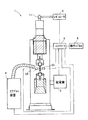
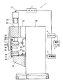
以下、本発明の端子かしめ装置および端子かしめ方法を具体化した最も好適な実施の形態について、図面に基づき詳細に説明する。そこで、本実施の形態に係る端子かしめ装置の概略構成を図1および図2に示す。図1は端子かしめ装置の概略構成を示す正面図であり、図2は端子かしめ装置の概略構成を示す側面図である。 BEST MODE FOR CARRYING OUT THE INVENTION Hereinafter, a most preferred embodiment embodying a terminal caulking device and a terminal caulking method of the present invention will be described in detail with reference to the drawings. Therefore, a schematic configuration of the terminal caulking device according to the present embodiment is shown in FIGS. FIG. 1 is a front view showing a schematic configuration of a terminal caulking device, and FIG. 2 is a side view showing a schematic configuration of the terminal caulking device.
この端子かしめ装置1には、図1に示すように、端子かしめ装置1を統括的に制御するコントローラ5が接続されている。このコントローラが、本発明の「温度判断手段」および「端子厚さ判断手段」の役割を担っている。そして、このコントローラ5には、各種制御を行うために、配電盤2、レギュレータ3、エアブロー装置4、操作パネル6、電磁センサ53、および赤外線温度センサ54が接続されている。配電盤2は、電極38,39に対する通電を制御するものであり、本発明の「通電制御手段」に相当する。また、レギュレータ3は、加圧シリンダ23への供給エア圧力を調整するものであり、これにより加圧シリンダ23による加圧動作が制御されるようになっている。つまり、このレギュレータ3が、本発明の「加圧制御手段」に相当する。
As shown in FIG. 1, a
端子かしめ装置1の本体部20には、図2に示すように、ガイド支持部21を介してガイド部22が支持され、ガイド部22には加圧シリンダ23が固定されるとともに、加圧シリンダ23と向き合うように下台19が設置されている。また、本体部20には配電盤2が接続されている。
As shown in FIG. 2, a
加圧シリンダ23には、エアパイプ11を介してレギュレータ3が接続されている。そして、加圧シリンダ23のピストン軸24は、ガイド部22の下方に突き出て設置されている。
The
ガイド部22には、透明に作られてなる前面カバー30が上下にスライド可能に設けられている。銅製の上部台座26は、ピストン軸24の下面に接するように固定され、銅製の下部台座27は、下台19の上面に固定されている。本体部20には、電流の経路であり弾性変形可能な一対の銅バー25が設けられ、それらが上部台座26および下部台座27にボルトで固定されている。
The
上部台座26には銅製の上部丸棒13が丸棒固定部28によって締着され、下部台座27には銅製の下部丸棒12が丸棒固定部28によって締着されている。そして、上部丸棒13の下端には上電極台座36が、下部丸棒12の上端には下電極台座35が各々向き合うようにボルトによって固定され、電極部10が形成されている。なお、上部丸棒13の上端および下部丸棒12の下端には冷却水入出孔33が備えられ、冷却水ホース(不図示)が接続されている。
A copper
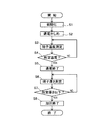
ここで、電極部10について図3を参照しながら説明する。図3は、電極部10の断面拡大図である。上部丸棒13、下部丸棒12の端部には、上電極台座36および下電極台座35がはめ込まれ、ボルト37により固定されている。タングステン製の上電極39、下電極38が、それぞれ上電極台座36、下電極台座35にはめ込まれ、ろう付けによって接着され固定されている。上電極39および下電極38は、平面で構成される当接面39a、当接面38aをそれぞれ備えている。
Here, the
上部丸棒13および下部丸棒12の内部には、冷却水路41が形成され、冷却水が循環している。下電極38の当接面38a上には、通電かしめされる対象である端子45が載置されている。端子45には、導電性の円環形状スリーブ46内にエナメル線束47が挿入されている。本実施の形態では、厚み1.0mmで直径10mmのスリーブ内に、直径0.85mmのエナメル線を45本挿入している。
A cooling
また、非接触状態で温度測定が可能な赤外線温度センサ54が、端子45近傍に固定され、端子45の端子温度TPが測定されるようになっている。この赤外線温度センサ54はコントローラ5に接続され、その測定値はリアルタイムにコントローラ5へ送られるようになっている。これにより、端子45の温度をモニタリングすることができるのである。
In addition, an
また、電磁スケール51が上電極39の上下動と共に移動するように、スケール取付部52によって上部丸棒13に取り付けられ、磁極を読み取る電磁センサ53が電磁スケール51の近傍に固定されている。この電磁センサ53はコントローラ5に接続され、その測定値はリアルタイムにコントローラ5へ送られるようになっている。電磁スケール51はS極とN極とが交互に備えられており、電磁センサ53により磁極の反転を検知することにより、上電極39の位置を測定することができるようになっている。そして、電磁スケール51、電磁センサ53により電極間距離測定機構(ストロークセンサ)が構成されている。
The
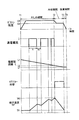
次に、上記した端子かしめ装置1の動作について、図4および図5を参照しながら説明する。図4は、かしめ方法の内容を示すフローチャートである。図5は、通電かしめのタイミングチャートである。
Next, the operation of the
まず、電極間距離測定機構の初期化が行われる(S1)。すなわち、操作パネル6を操作して初期化を行うと、電極間に何も存在しない状態で、図3において、上電極の当接面39aと下電極の当接面38aとが当接させられ、この時の上電極39の初期位置が電磁センサ53により測定されコントローラ5へ送られて記憶される。この初期位置と上電極の当接面39aとの距離を電極間距離Lと定義する。そして、前面カバー30を手動で上方にスライドさせカバー開状態とし、端子45を下電極の当接面38a上に載置した後、前面カバー30を下方にスライドさせカバー閉状態とする。この前面カバー30は、作業員の安全を確保するものである。
First, the inter-electrode distance measuring mechanism is initialized (S1). That is, when initialization is performed by operating the
続いて、通電かしめが行われる(S2)。すなわち、図5に示すように、時刻T1において操作パネル6を操作して通電かしめを開始すると、レギュレータ3によりエアがエアパイプ11を介して加圧シリンダ23に送り込まれ、ピストン軸24が下方へ伸び出る。そして、ピストン軸24の動作に応じて上部台座26および上部丸棒13が下方へ移動する。なお、上部台座26は、本体部20と弾力性のある銅バー25で接続されているため、上下移動が可能である。
Subsequently, energization caulking is performed (S2). That is, as shown in FIG. 5, when the
これにより、図3に示すように、上電極39の当接面39aと下電極38の当接面38aとによって、端子45が挟まれる。この端子45を挟んだときの電極間距離Lは、端子45の初期端子厚さL1である。そして、ピストン軸24に予熱時荷重D1がかけられる。このとき、予熱時荷重D1の調節はレギュレータ3から加圧シリンダ23に送られるエア圧力の調整により行われる。なお、本実施の形態では、かしめ時荷重D1は例えば約10kNの荷重が用いられる。
Thereby, as shown in FIG. 3, the terminal 45 is sandwiched between the
そして、予熱時荷重D1がかけられ加圧状態とされると、次に通電が開始される。図2において、配電盤2から端子かしめ装置1の本体部20に電源が供給され、上側の銅バー25、上部台座26、上部丸棒13、上電極台座36、下電極台座35、下部丸棒12、下部台座27、下側の銅バー25によって形成される経路を電流が流れる。このとき、図3において、タングステン製の上電極39、下電極38の電気抵抗は、他の銅製の経路の電気抵抗に比して高いため発熱する。なお、電極38,39に対する通電は、通電電流I(kA)をX秒間流した後にX0秒間停止するというサイクルを繰り返すことにより行われる。本実施形態では通電電流Iは10(kA)、Xは1秒間、X0は1/6秒間に設定している。
And if the preheating load D1 is applied and it will be in a pressurization state, electricity supply will be started next. In FIG. 2, power is supplied from the
これにより、端子45のエナメル線束47のエナメル被覆が溶融・気化して除去され導電性が確保された上で、エナメル被覆が除去された部位とスリーブ46とがかしめられる。このとき、端子45の温度が赤外線温度センサ54に測定されており(S3)、コントローラ5によって、端子45の温度が所定温度(かしめ端子温度TP2)に達したか否かが判断される(S4)。端子45の温度がかしめ端子温度TP2に達していない場合には(S4:NO)、S3および54の処理が繰り返される。そして、端子45の温度がかしめ端子温度TP2に達すると(S4:YES)、コントローラ5から配電盤2へ電源供給を停止する信号が発信され、電極38,39への通電が終了する(S5)。本実施の形態では、図5に示すように、端子45の温度が時刻T2にかしめ端子温度TP2に達しているので、時刻T2にかしめ期間が終了する。
As a result, the enamel coating of the
ここで、かしめ端子温度TP2は、約400〜600℃の範囲に設定すればよい。この温度範囲に設定することにより、端子45の温度を確実にこの温度まで上昇させられるので、エナメル線束47のエナメル被覆を確実に溶かして除去すことができるからである。本実施の形態では、かしめ端子温度TP2を「500℃」に設定している。
Here, the caulking terminal temperature TP2 may be set in a range of about 400 to 600 ° C. By setting the temperature within this temperature range, the temperature of the terminal 45 can be reliably raised to this temperature, so that the enamel coating of the
このように、本実施の形態では通電かしめ時において、端子45の温度をモニタリングしているので、端子45の初期温度TP1に関わらず、端子45の温度をエナメル線束47のエナメル被覆を完全に溶かして除去すことができる温度(かしめ端子温度TP2)まで安定して上昇させることができる。したがって、環境温度の違いあるいは電極の劣化などによる抵抗値の変化などによって、通電かしめ時における端子45の最高温度が変化することがない。よって、エナメル線束47のエナメル被覆を完全に溶かして除去すことができるので、かしめ不良が発生しない。
Thus, in this embodiment, since the temperature of the terminal 45 is monitored during the caulking, the temperature of the terminal 45 is completely dissolved in the enamel coating of the
また、端子45の温度をモニタリングしているので、端子45の温度が過度に上昇することがないから、通電電流値を大きくして短時間通電を行うことができる。例えば、通電電流20(kA)を数秒間(端子45の温度がかしめ端子温度TP2に達するまでの時間)だけ流せばよい。これにより、通電停止時間がなくなり端子45の温度上昇速度が早まるので、かしめ加工時間の短縮を図ることができる。 Moreover, since the temperature of the terminal 45 is monitored, the temperature of the terminal 45 does not rise excessively, so that the energization current value can be increased and the energization can be performed for a short time. For example, the energizing current 20 (kA) may be allowed to flow for several seconds (the time until the temperature of the terminal 45 reaches the terminal temperature TP2). As a result, the energization stop time is eliminated and the temperature rise rate of the terminal 45 is increased, so that the caulking time can be shortened.
そして時刻T2において、電極38,39への通電が終了すると、端子45の厚さ、つまり電極間距離が測定される(S6)。このとき、図5に示すように、かしめ期間から冷却期間(時刻T2からT3までの期間)へと移行する。冷却期間においては、ピストン荷重をかしめ時荷重D1から冷却時荷重D2へ下げる信号がコントローラ5からレギュレータ3へ発せられるとともに、コントローラ5からエアブロー装置4へエアブロー開始の信号が発信されエアブロー装置4が作動し、エアブロー管50を介して端子45および上電極39、下電極38に送風される。これにより、端子45および上下電極38,39が冷却される。
When the energization of the
このとき、端子45が、上電極39と下電極38とで冷却時荷重D2で挟まれる状態で冷却されることにより、端子45が送風により動くことを防止することができる。また端子45だけでなく、上電極39および下電極38もあわせて冷却する効果を得ることができる。
At this time, the terminal 45 is cooled while being sandwiched by the cooling load D2 between the
そして、冷却期間の終了の検知は、端子45の厚さが所定厚LF以下になったことを電磁センサ53で検出、コントローラ5が判断したことにより行われる。このため、コントローラ5により、端子45の厚さが所定厚LF以下になったか否かが判断されており(S7)、端子45の厚さが所定厚LF以下になるまで、S6およびS7の処理が繰り返し行われる(S7:NO)。そして、端子45の厚さが所定厚LF以下になると(S7:YES)、コントローラ5からエアブロー装置4へ送風を停止する信号が発信され、エアブロー管50からの送風が停止されるとともに、端子45の加圧が終了する(S8)。かくして、冷却期間が終了する。図5に示すように、本実施の形態では冷却期間の終了は、時刻T3の時点となる。なお、本実施の形態では、所定厚LFを「3.60mm」に設定している。
The end of the cooling period is detected when the
端子45への加圧が終了して、冷却期間から抜重期間(時刻T3からT4までの期間)へ移行すると、上電極39と端子45とを離間させる信号がコントローラ5からレギュレータ3へ発せられ、ピストン荷重は冷却時荷重D2からゼロになる。そして、最後に前面カバー30を上方にスライドさせカバー開状態とし、通電かしめ後の端子45を下電極の当接面38a上から取り除くことで全工程が終了する。
When the pressurization to the terminal 45 is finished and the transition from the cooling period to the extraction period (period from time T3 to T4) is made, a signal for separating the
このように、本実施の形態では、端子45の厚さが所定厚LF以下になったときに、端子45に対する加圧が終了する。そして、上記したように、端子45の最高温度は常に一定(かしめ端子温度TP2)であるので、室温へ冷却される際の熱収縮量は常に一定となるから、端子かしめ量を常に一定に管理することができる。これにより、かしめ不良を確実に発生させないことができる。 As described above, in the present embodiment, when the thickness of the terminal 45 becomes equal to or less than the predetermined thickness LF, the pressurization to the terminal 45 is finished. As described above, since the maximum temperature of the terminal 45 is always constant (caulking terminal temperature TP2), the amount of thermal shrinkage when cooling to room temperature is always constant, so the terminal caulking amount is always managed constant. can do. Thereby, it is possible to reliably prevent caulking defects.
以上、詳細に説明したように本実施の形態に係る端子かしめ装置1によれば、赤外線温度センサ54により端子45の温度を測定し、コントローラ5によりその測定温度がかしめ端子温度TP2(500℃)に達したときに、電極38,39に対する通電が終了する。このため、環境温度の違いあるいは電極の劣化などによる抵抗値の変化などに影響されることなく、かしめ時に端子45の温度がかしめ端子温度TP2(最適最高温度)まで確実に上昇する。したがって、エナメル線束47のエナメル被覆を確実に溶かして除去することができるので、かしめ不良が発生しない。
As described above, according to the
また、本発明に係る端子かしめ装置1においては、通電終了後に電磁スケール12および電磁センサ53により端子45の厚さを測定し、コントローラ5によりその厚さが所定厚LF(3.60mm)以下になったときに、端子45に対する加圧が終了する。そして、上記したように、端子45の最高温度は常に一定であるので、室温へ冷却される際の熱収縮量は常に一定となるから、端子かしめ量を一定に管理することができる。これにより、確実にかしめ不良を発生させないことができる。
In the
なお、上記した実施の形態は単なる例示にすぎず、本発明を何ら限定するものではなく、その要旨を逸脱しない範囲内で種々の改良、変形が可能であることはもちろんである。例えば、上記した実施の形態では、赤外線温度センサ54により、端子45の端子温度TPを測定しているが、測定する部位は端子に限られず上電極39、下電極38等を測定するようにしてもよい。この場合の通電終了判断温度(かしめ端子温度TP2に相当)は、約700〜900℃の範囲内で設定すればよい。もちろん、端子45の温度と、電極38,39の両方の温度を測定して、通電終了時を判断するようにしてもよい。
It should be noted that the above-described embodiment is merely an example and does not limit the present invention in any way, and various improvements and modifications can be made without departing from the scope of the invention. For example, in the above-described embodiment, the terminal temperature TP of the terminal 45 is measured by the
また、上記した実施の形態では、電磁スケール51、電磁センサ53により電極間距離測定機構(ストロークセンサ)が構成されるとしたが、レーザ発光部、レーザ受光部およびレーザを通すスリットを有するスケールにより電極間距離測定機構を構成してもよい。
In the above-described embodiment, the inter-electrode distance measuring mechanism (stroke sensor) is configured by the
1 端子かしめ装置
2 配電盤
3 レギュレータ
5 コントローラ
6 操作パネル
23 加圧シリンダ
38 下電極
39 上電極
45 端子
51 磁気スケール
53 電磁センサ
54 赤外線温度センサ
TP1 初期端子温度
TP2 かしめ端子温度
D1 かしめ時荷重
D2 冷却時荷重
LF 所定厚
1
Claims (4)
通電加熱中における前記電極の温度を測定する電極温度センサ、あるいは通電加熱中における前記端子の温度を測定する端子温度センサの少なくとも一方と、
前記電極温度センサまたは前記端子温度センサで測定される温度が所定温度に達したか否か判断する温度判断手段と、
前記温度判断手段で前記所定温度に達したと判断された場合に、前記電極への通電を終了する通電制御手段と、を有することを特徴とする端子かしめ装置。 In a terminal caulking device for caulking the electric wire to the terminal, by sandwiching the terminal into which the electric wire is inserted between a pair of electrodes and heating and applying pressure while applying a load,
At least one of an electrode temperature sensor that measures the temperature of the electrode during current heating, or a terminal temperature sensor that measures the temperature of the terminal during current heating,
Temperature determining means for determining whether the temperature measured by the electrode temperature sensor or the terminal temperature sensor has reached a predetermined temperature;
A terminal caulking device comprising: energization control means for terminating energization of the electrodes when the temperature determination means determines that the predetermined temperature has been reached.
前記電極の間の距離から前記端子の厚さを測定するストロークセンサと、
前記ストロークセンサで測定される前記端子の厚さが所定厚さ以下になったか否かを判断する端子厚さ判断手段と、
前記端子厚さ判断手段で前記所定厚さ以下になったと判断された場合に、前記電極による前記端子への加圧を終了する加圧制御手段と、を有することを特徴とする端子かしめ装置。 In the terminal caulking device according to claim 1,
A stroke sensor that measures the thickness of the terminal from the distance between the electrodes;
Terminal thickness determining means for determining whether the thickness of the terminal measured by the stroke sensor is equal to or less than a predetermined thickness;
A terminal caulking device comprising pressurizing control means for ending pressurization of the terminal by the electrode when the terminal thickness judging means judges that the predetermined thickness or less is reached.
通電加熱中における前記電極あるいは前記端子の少なくとも一方の温度を測定し、
その測定された温度が所定温度に達した場合に、前記電極への通電を終了することを特徴とする端子かしめ方法。 In the terminal caulking method for caulking the electric wire to the terminal, by sandwiching the terminal into which the electric wire is inserted between a pair of electrodes, and applying heat while applying pressure while applying a load,
Measure the temperature of at least one of the electrode or the terminal during current heating,
A terminal caulking method characterized in that energization of the electrode is terminated when the measured temperature reaches a predetermined temperature.
前記電極の間の距離に基づき前記端子の厚さを測定し、
その測定された厚さが所定値以下になった場合に、前記電極による前記端子への加圧を終了することを特徴とする端子かしめ方法。
In the terminal caulking method according to claim 3,
Measuring the thickness of the terminal based on the distance between the electrodes;
A terminal caulking method, wherein pressurization of the terminal by the electrode is terminated when the measured thickness becomes a predetermined value or less.
Priority Applications (1)
| Application Number | Priority Date | Filing Date | Title |
|---|---|---|---|
| JP2003401164A JP4259294B2 (en) | 2003-12-01 | 2003-12-01 | Terminal caulking device and terminal caulking method |
Applications Claiming Priority (1)
| Application Number | Priority Date | Filing Date | Title |
|---|---|---|---|
| JP2003401164A JP4259294B2 (en) | 2003-12-01 | 2003-12-01 | Terminal caulking device and terminal caulking method |
Publications (2)
| Publication Number | Publication Date |
|---|---|
| JP2005166330A true JP2005166330A (en) | 2005-06-23 |
| JP4259294B2 JP4259294B2 (en) | 2009-04-30 |
Family
ID=34725177
Family Applications (1)
| Application Number | Title | Priority Date | Filing Date |
|---|---|---|---|
| JP2003401164A Expired - Fee Related JP4259294B2 (en) | 2003-12-01 | 2003-12-01 | Terminal caulking device and terminal caulking method |
Country Status (1)
| Country | Link |
|---|---|
| JP (1) | JP4259294B2 (en) |
Cited By (5)
| Publication number | Priority date | Publication date | Assignee | Title |
|---|---|---|---|---|
| JP2009170227A (en) * | 2008-01-15 | 2009-07-30 | Yazaki Corp | Terminal crimping method and terminal crimping apparatus |
| JP2009190060A (en) * | 2008-02-14 | 2009-08-27 | Denso Corp | Fusing control method and fusing device |
| JP2009208128A (en) * | 2008-03-05 | 2009-09-17 | Denso Corp | Method and apparatus for fusing quality control |
| WO2015014647A1 (en) * | 2013-07-29 | 2015-02-05 | Siemens Aktiengesellschaft | Crimped connection |
| JP2015199090A (en) * | 2014-04-08 | 2015-11-12 | 日産自動車株式会社 | Thermal caulking device and thermal caulking control method |
Citations (8)
| Publication number | Priority date | Publication date | Assignee | Title |
|---|---|---|---|---|
| JPH0878131A (en) * | 1994-06-27 | 1996-03-22 | Seiko Epson Corp | Conductor connection method and conductor connection end structure |
| JPH1110351A (en) * | 1997-06-19 | 1999-01-19 | Kyoshin Kogyo Kk | Resistance welding apparatus |
| JPH1140310A (en) * | 1997-05-19 | 1999-02-12 | Toyota Motor Corp | Electric caulking device |
| JPH11138275A (en) * | 1997-11-06 | 1999-05-25 | Toyota Motor Corp | Bonding method of coated conductive member |
| JP2000150104A (en) * | 1998-11-09 | 2000-05-30 | Kodera Denshi Seisakusho:Kk | Temperature compensator for terminal crimping machine |
| JP2002111195A (en) * | 2000-09-29 | 2002-04-12 | Nippon Avionics Co Ltd | Coated fine wire reflow device |
| JP2002134246A (en) * | 2000-10-27 | 2002-05-10 | Dengensha Mfg Co Ltd | Method and apparatus for electrical thermal caulking of insulated wire |
| JP2004208347A (en) * | 2002-12-24 | 2004-07-22 | Aisin Seiki Co Ltd | Stripping equipment for coated wire |
-
2003
- 2003-12-01 JP JP2003401164A patent/JP4259294B2/en not_active Expired - Fee Related
Patent Citations (8)
| Publication number | Priority date | Publication date | Assignee | Title |
|---|---|---|---|---|
| JPH0878131A (en) * | 1994-06-27 | 1996-03-22 | Seiko Epson Corp | Conductor connection method and conductor connection end structure |
| JPH1140310A (en) * | 1997-05-19 | 1999-02-12 | Toyota Motor Corp | Electric caulking device |
| JPH1110351A (en) * | 1997-06-19 | 1999-01-19 | Kyoshin Kogyo Kk | Resistance welding apparatus |
| JPH11138275A (en) * | 1997-11-06 | 1999-05-25 | Toyota Motor Corp | Bonding method of coated conductive member |
| JP2000150104A (en) * | 1998-11-09 | 2000-05-30 | Kodera Denshi Seisakusho:Kk | Temperature compensator for terminal crimping machine |
| JP2002111195A (en) * | 2000-09-29 | 2002-04-12 | Nippon Avionics Co Ltd | Coated fine wire reflow device |
| JP2002134246A (en) * | 2000-10-27 | 2002-05-10 | Dengensha Mfg Co Ltd | Method and apparatus for electrical thermal caulking of insulated wire |
| JP2004208347A (en) * | 2002-12-24 | 2004-07-22 | Aisin Seiki Co Ltd | Stripping equipment for coated wire |
Cited By (7)
| Publication number | Priority date | Publication date | Assignee | Title |
|---|---|---|---|---|
| JP2009170227A (en) * | 2008-01-15 | 2009-07-30 | Yazaki Corp | Terminal crimping method and terminal crimping apparatus |
| JP2009190060A (en) * | 2008-02-14 | 2009-08-27 | Denso Corp | Fusing control method and fusing device |
| JP2009208128A (en) * | 2008-03-05 | 2009-09-17 | Denso Corp | Method and apparatus for fusing quality control |
| WO2015014647A1 (en) * | 2013-07-29 | 2015-02-05 | Siemens Aktiengesellschaft | Crimped connection |
| CN105324889A (en) * | 2013-07-29 | 2016-02-10 | 西门子公司 | crimp connection |
| CN105324889B (en) * | 2013-07-29 | 2018-06-26 | 西门子公司 | crimp connection |
| JP2015199090A (en) * | 2014-04-08 | 2015-11-12 | 日産自動車株式会社 | Thermal caulking device and thermal caulking control method |
Also Published As
| Publication number | Publication date |
|---|---|
| JP4259294B2 (en) | 2009-04-30 |
Similar Documents
| Publication | Publication Date | Title |
|---|---|---|
| JP4259294B2 (en) | Terminal caulking device and terminal caulking method | |
| JP4344397B1 (en) | Thermal caulking method and apparatus using electrothermal welding tip | |
| US20070262058A1 (en) | Welding system and method having power controller with workpiece sensor | |
| JP6813298B2 (en) | Joining device | |
| JP2005059025A (en) | Terminal crimping apparatus and terminal crimping method | |
| JP2007178166A (en) | Heater disconnection detection method | |
| JP4582162B2 (en) | Fusing quality control method and apparatus | |
| JP4281459B2 (en) | Terminal crimping method | |
| JP5666973B2 (en) | Fusing method and fusing apparatus | |
| EP0480301A2 (en) | Fusing apparatus with temperature control | |
| JP2003320454A (en) | Method and apparatus for hot wire welding | |
| JPH1110351A (en) | Resistance welding apparatus | |
| JPS63317621A (en) | Electrical heating method | |
| CN114713954B (en) | Welding equipment and welding method | |
| JP7561922B1 (en) | Resistance welding machine and method for controlling resistance welding machine | |
| JP3438338B2 (en) | Energization control method of electrofusion type pipe joint | |
| JP2005063710A (en) | Terminal crimping device | |
| JPH0371982A (en) | Resistance welding method | |
| JPH02231127A (en) | Method and apparatus for fusion of electrofusion joint | |
| JPH02309382A (en) | Control device for heat fixing device | |
| JP4313445B2 (en) | Fusion fusion control method and fusion control device for electric fusion joint | |
| JP5000286B2 (en) | Heat caulking method and heat caulking device | |
| JPH0631811A (en) | Method for controlling electric welding machine | |
| JPH07256761A (en) | Method of controlling energization of electric fusion joint | |
| JP2023105604A (en) | THERMAL SHOCK TEST SYSTEM AND THERMAL SHOCK TEST METHOD |
Legal Events
| Date | Code | Title | Description |
|---|---|---|---|
| A621 | Written request for application examination |
Free format text: JAPANESE INTERMEDIATE CODE: A621 Effective date: 20060925 |
|
| A977 | Report on retrieval |
Free format text: JAPANESE INTERMEDIATE CODE: A971007 Effective date: 20081006 |
|
| A131 | Notification of reasons for refusal |
Free format text: JAPANESE INTERMEDIATE CODE: A131 Effective date: 20081014 |
|
| A521 | Written amendment |
Free format text: JAPANESE INTERMEDIATE CODE: A523 Effective date: 20081119 |
|
| TRDD | Decision of grant or rejection written | ||
| A01 | Written decision to grant a patent or to grant a registration (utility model) |
Free format text: JAPANESE INTERMEDIATE CODE: A01 Effective date: 20090120 |
|
| A01 | Written decision to grant a patent or to grant a registration (utility model) |
Free format text: JAPANESE INTERMEDIATE CODE: A01 |
|
| A61 | First payment of annual fees (during grant procedure) |
Free format text: JAPANESE INTERMEDIATE CODE: A61 Effective date: 20090202 |
|
| FPAY | Renewal fee payment (event date is renewal date of database) |
Free format text: PAYMENT UNTIL: 20120220 Year of fee payment: 3 |
|
| R151 | Written notification of patent or utility model registration |
Ref document number: 4259294 Country of ref document: JP Free format text: JAPANESE INTERMEDIATE CODE: R151 |
|
| FPAY | Renewal fee payment (event date is renewal date of database) |
Free format text: PAYMENT UNTIL: 20120220 Year of fee payment: 3 |
|
| FPAY | Renewal fee payment (event date is renewal date of database) |
Free format text: PAYMENT UNTIL: 20120220 Year of fee payment: 3 |
|
| FPAY | Renewal fee payment (event date is renewal date of database) |
Free format text: PAYMENT UNTIL: 20130220 Year of fee payment: 4 |
|
| FPAY | Renewal fee payment (event date is renewal date of database) |
Free format text: PAYMENT UNTIL: 20130220 Year of fee payment: 4 |
|
| FPAY | Renewal fee payment (event date is renewal date of database) |
Free format text: PAYMENT UNTIL: 20140220 Year of fee payment: 5 |
|
| LAPS | Cancellation because of no payment of annual fees |