JP2005143630A - Double container - Google Patents
Double container Download PDFInfo
- Publication number
- JP2005143630A JP2005143630A JP2003382276A JP2003382276A JP2005143630A JP 2005143630 A JP2005143630 A JP 2005143630A JP 2003382276 A JP2003382276 A JP 2003382276A JP 2003382276 A JP2003382276 A JP 2003382276A JP 2005143630 A JP2005143630 A JP 2005143630A
- Authority
- JP
- Japan
- Prior art keywords
- container
- inner container
- outer container
- glass
- fitting
- Prior art date
- Legal status (The legal status is an assumption and is not a legal conclusion. Google has not performed a legal analysis and makes no representation as to the accuracy of the status listed.)
- Pending
Links
Images


Abstract
Description
本発明は、例えばアイスクリームやシャーベット等の氷菓子を作ったり、ビールに代表される飲料を保冷したりする有底筒形の二重容器に関する。 The present invention relates to a bottomed cylindrical double container for making ice confectionery such as ice cream or sherbet or for keeping a beverage typified by beer cold.
従来の二重容器としては、内容器と外容器の双方を硬質樹脂で作り、内容器と外容器の上部に有するリング状の凹凸を嵌め合わせることによって内容器と外容器を密着させ、内容器と外容器の間に形成される断熱空間を密閉するものが知られている(特許文献1)。ちなみに、二重容器は、断熱空間の密閉度によって保温性に差ができることから、密閉度を確保することは重要である。また、内容器と外容器に硬質樹脂を用いたのは、二重容器の中に液体等を入れた場合にでもその重量に耐えて容器形状を維持するためである。ところが、硬質樹脂の二重容器は、その素材ゆえ口を付けたときの感触がガラス製の二重容器よりも悪い。
また、従来の二重容器としては、内容器と外容器の双方をガラスで作り、内容器と外容器の上部をOリングを介して密着したものもあるが、Oリングの分だけ部品点数が増える。 In addition, as a conventional double container, both the inner container and the outer container are made of glass, and the upper part of the inner container and the outer container are in close contact with each other through an O-ring. Increase.
そこで本発明者は、内容器をガラス製にすると共に外容器を硬質樹脂製にし、凹凸を利用して内外の容器を嵌め合わせ、ガラス製の内容器を外容器よりも上方に突き出す構造にすることによって、上記問題を解決できないかと考えた。しかし、ガラス製の内容器は変形しないことから、嵌め合わせの際に硬質樹脂製の外容器が能力以上に広がって割れることになった。ちなみに、内容器と外容器の双方が硬質樹脂製の場合は、外容器が広がるだけでなく、内容器が縮むことによって、破損することなく嵌め合わせが可能であった。 Therefore, the present inventor makes the inner container made of glass and the outer container made of a hard resin, fits the inner and outer containers using the unevenness, and projects the inner container made of glass upward from the outer container. I thought that the above problem could be solved. However, since the inner container made of glass is not deformed, the outer container made of hard resin spreads beyond its capacity and cracks during fitting. By the way, when both the inner container and the outer container are made of hard resin, not only the outer container spreads but also the inner container shrinks and can be fitted without being damaged.
本発明は上記実情を考慮して創作されたもので、ガラス製の内容器と硬質樹脂製の外容器を破損することなく嵌め合わせて密着させることを解決課題とする。 The present invention has been created in view of the above circumstances, and an object of the present invention is to fit the glass inner container and the hard resin outer container together without causing damage.
本発明は、有底筒形の内容器の外側を断熱空間を介して外容器で覆い、内容器の上部と外容器の上部のうち一方に凸条を、他方に凹溝をそれぞれ設け、凸条と凹溝の嵌り合いによって内容器と外容器の上部を周方向に沿って密着させる二重容器を前提とする。 The present invention covers the outer side of a bottomed cylindrical inner container with an outer container through a heat-insulating space, and provides a convex groove on one of the upper part of the inner container and the upper part of the outer container, and a concave groove on the other. It is premised on a double container in which the inner container and the upper part of the outer container are brought into close contact with each other in the circumferential direction by fitting the groove and the groove.
そして、請求項1の発明は、内容器の素材にはガラスを用いると共に、外容器の素材には容器形状を維持する硬質性と嵌め合わせの際の柔軟性を兼備した樹脂を用い、熱収縮可能な温度の外容器に内容器を圧入し、ガラスの内容器の上端部を外容器よりも上方に突出させて口部とし、熱収縮を利用して凸条と凹溝を密着させることを特徴とする。 The invention of claim 1 uses glass as the material of the inner container, and uses heat-shrinkable resin as the material of the outer container that has both the rigidity to maintain the shape of the container and the flexibility at the time of fitting. The inner container is press-fitted into the outer container at a possible temperature, the upper end of the glass inner container protrudes upward from the outer container to form a mouth, and the ridges and the grooves are brought into close contact using heat shrinkage. Features.
外容器は不透明であっても良いが、二重容器の中に入れた飲料物等が容器越しに見えるようにするには、透明なものを用いる。このようにすれば、凹溝と凸条との密着には熱収縮を利用し、Oリングや接着剤を使ってないので、体裁の良い透明な外観性が保たれる。 The outer container may be opaque, but a transparent one is used so that beverages or the like placed in the double container can be seen through the container. In this way, heat shrinkage is used for the close contact between the groove and the ridge, and no O-ring or adhesive is used, so that a transparent appearance with good appearance can be maintained.
凸条を樹脂製の外容器に、凹溝をガラス製の内容器にそれぞれ設けた場合、ガラス製の内容器はその内周面の凹溝に対応する箇所が成形後の固化中のヒケによって窪むことになる。内周面にリング状に窪む箇所があると、汚れが溜まりやすいし、二重容器の内面を洗い難くなる。これを防ぐには、請求項2の発明のように凸条をガラス製の内容器に、凹溝を樹脂製の外容器にそれぞれ設けることが望ましい。凸条をガラス製の内容器に設ければ、内容器の内周面がでこぼこの無い滑らかな筒状曲面となる。 When the ridge is provided on the resin outer container and the concave groove is provided on the glass inner container, the glass inner container has a portion corresponding to the concave groove on the inner peripheral surface thereof due to sinking during solidification after molding. It will be depressed. If there is a ring-shaped recess on the inner peripheral surface, dirt tends to accumulate and it becomes difficult to wash the inner surface of the double container. In order to prevent this, it is desirable to provide the ridges in the glass inner container and the grooves in the resin outer container as in the second aspect of the invention. If the ridges are provided on the inner container made of glass, the inner peripheral surface of the inner container becomes a smooth cylindrical curved surface with no bumps.
請求項1の発明は、外容器の材料に硬質性と柔軟性を兼備した樹脂を用い、しかも、熱収縮可能な温度の外容器に内容器を圧入するという、工夫を組み合わせることによって、ガラス製の内容器を樹脂製の外容器に圧入しても、外容器が割れることなく嵌り合うことが可能となった。そして、ガラス製の口部により、口を付けた時に良好な感触が得られる。また、熱収縮によって凹溝と凸条を密着させて断熱空間を形成するので、従来のようなOリングが不要となり、その結果、部品点数が少なくてすみ、生産コストが安くなる。 The invention of claim 1 is made of glass by combining a device that uses a resin having both rigidity and flexibility as the material of the outer container, and press-fitting the inner container into the outer container having a heat shrinkable temperature. Even if the inner container is press-fitted into the resin-made outer container, the outer container can be fitted without breaking. Then, the glass mouth provides a good feel when the mouth is attached. In addition, since the heat insulating shrinkage space is formed by closely contacting the grooves and the ridges by heat shrinkage, the conventional O-ring is unnecessary, and as a result, the number of parts is reduced and the production cost is reduced.
請求項2の発明は、凸条をガラス製の内容器に設けてあるので、内容器の内周面の凸条に対応する箇所が成形後の固化中に窪まずに、内周面全域がでこぼこの無い滑らかな筒状曲面となる。従って、内容器の内面に汚れが溜まりにくいし、洗いやすい。 In the invention of claim 2, since the ridges are provided in the inner container made of glass, the portion corresponding to the ridges on the inner peripheral surface of the inner container is not depressed during solidification after molding, and the entire inner peripheral surface is not formed. A smooth cylindrical curved surface without bumps. Therefore, it is difficult for dirt to collect on the inner surface of the inner container and it is easy to wash.
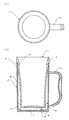
本発明の二重容器の第一例は図1、図2に示すように透明なガラス製の内容器1と透明な樹脂製の外容器2とからなるジョッキ形態のものである。 As shown in FIGS. 1 and 2, the first example of the double container of the present invention is a mug-shaped one comprising a transparent glass inner container 1 and a transparent resin outer container 2.
内容器1は有底円筒形であって、その上端部を口部3とし、口部3をそれよりも下側より段差状に外側に張り出している。また、内容器1の外周面であって口部3の下側近傍にはリング状の凸条4を外周方向に沿って突出してある。一方、内容器1の内周面は、段差の殆ど無い滑らかな筒状の曲面である。 The inner container 1 has a bottomed cylindrical shape, and an upper end portion of the inner container 1 serves as a mouth portion 3, and the mouth portion 3 projects outwardly in a step shape from the lower side. A ring-shaped ridge 4 is projected along the outer peripheral direction on the outer peripheral surface of the inner container 1 and in the vicinity of the lower side of the mouth 3. On the other hand, the inner peripheral surface of the inner container 1 is a smooth cylindrical curved surface with almost no steps.
外容器2は内容器1よりも一回り大きな有底円筒形であって、その内周面の上端部には凸条4を嵌め込むリング状の凹溝5が内周方向に沿って形成してある。また、凹溝5と凸条4を利用して外容器2と内容器1を嵌め合わせて密着させると、外容器2と内容器1の間に断熱空間6が形成されると共に、外容器2の上端が内容器1の口部3の下に隙間無く密着する。外容器2の底壁7の周縁部には上方に突き出す位置決めリブ8を周方向に間隔をあけて設け、これら位置決めリブ8に内容器1の下端部外周面が当たることになる。外容器2の底壁7には空気抜孔9をあけ、空気抜孔9に栓10を詰めて断熱空間6を密閉する。符号11は持ち手である。
The outer container 2 has a bottomed cylindrical shape that is slightly larger than the inner container 1, and a ring-shaped
外容器2の素材には、スチロールと、株式会社旭化成が製造販売している商品名アサフレックス(登録商標)を50:50〜70:30(重量%)の割合で混合したものを用いる。容器形状を維持するための硬質性をスチロールによって持たせ、凹溝5と凸条4を嵌め合わせる際に必要な柔軟性をアサフレックスによって持たせてある。スチロールの配合割合を上述した範囲の上限よりも増やすと、外容器2が硬くなって圧入時に割れる。一方、アサフレックスの配合割合を上述した範囲の上限よりも増やすと、外容器2が柔らかくなって容器形状を維持できなくなる。アサフレックスは、スチレン・ブタジエンブロックコポリマーで、高い透明性、優れた耐衝撃性、優れたヒンジ特性を発揮し、スチレン系樹脂との相容性に優れ、耐衝撃性を改良するものである。
As the material of the outer container 2, a mixture of styrene and the trade name Asaflex (registered trademark) manufactured and sold by Asahi Kasei Co., Ltd. at a ratio of 50:50 to 70:30 (% by weight) is used. Stiffness for maintaining the container shape is provided by styrene, and flexibility necessary for fitting the
第一例の二重容器の作り方は、外容器2に内容器1を圧入する仕方である。ここでの注意点の一つ目は、外容器2には成形直後の熱いもの、60℃〜100℃のものを用いる点である。この点を注意すれば、圧入時の凹凸の嵌め合わせによって外容器2が瞬間的に広がっても割れるおそれはない。そして、自然冷却によって外容器2が熱収縮するので、外容器2と内容器1が完全に一体化する。注意点の二つ目は、外容器2の空気抜孔9をあけたまま圧入し、圧入後に栓10を詰めることである。空気抜孔9に栓10が詰めてあると、内容器1を外容器2に圧入する際に空気が抜けないことから圧入ができなくなる。なお、ガラス製の内容器1の成形は、プレスブロー成形を用いる。つまり、溶融したガラスを金型内に投入し、プレスによって金型に溶融ガラスをある程度沿わせ、その後、エアブローすることによって金型に溶融ガラスを正確に沿わせて所望の形状とする成形方法である。
In the first example, the double container is made by press-fitting the inner container 1 into the outer container 2. The first point to be noted here is that the outer container 2 is a hot one immediately after molding, that is 60 ° C to 100 ° C. If attention is paid to this point, there is no possibility of cracking even if the outer container 2 spreads momentarily due to the fitting of irregularities during press-fitting. Since the outer container 2 is thermally contracted by natural cooling, the outer container 2 and the inner container 1 are completely integrated. The second point of caution is to press fit with the air vent hole 9 of the outer container 2 open, and to plug the
本発明の二重容器の第二例は図3に示すように、内容器1と外容器2の間の断熱空間6に保冷剤12を充填してあることを特徴とする。これによって、保冷効果が長時間に亘って持続する。
As shown in FIG. 3, the second example of the double container according to the present invention is characterized in that the
また、外容器2は、持ち手が付いた筒状の外周壁13と、底壁7を別々に成形し、外周壁13の下端に底壁7を超音波溶着したものを用い、底壁7には第一例よりも大きな空気抜孔9をあけて、その大きさに合わせた栓10を使用してある。
The outer container 2 is formed by separately forming a cylindrical outer
保冷剤12としては、例えば小麦澱粉などの有機増粘剤に水を加えてペースト状物を調整し、これに塩化ナトリウムを主成分とする塩を5〜16重量%添加して粘度を2〜3000ポイズにしてなるものを用いる。このような保冷剤は−200℃程度に冷却されてもペースト状態を保ち、その温度低下に伴う膨張が小さく、このため内容器1や外容器2が変形したり破損したりするのを防止できる。なお、保冷剤の代わりに、保温材を用いても良い。
As the
1 内容器
2 外容器
3 口部
4 凸条
5 凹溝
6 断熱空間
DESCRIPTION OF SYMBOLS 1 Inner container 2 Outer container 3 Mouth part 4
Claims (2)
内容器(1)の素材にはガラスを用いると共に、外容器(2)の素材には容器形状を維持する硬質性と嵌め合わせの際の柔軟性を兼備した樹脂を用い、熱収縮可能な温度の外容器(2)に内容器(1)を圧入し、ガラスの内容器(1)の上端部を外容器(2)よりも上方に突出させて口部(3)とし、熱収縮を利用して凸条(4)と凹溝(5)を密着させることを特徴とする二重容器。 The outer side of the bottomed cylindrical inner container (1) is covered with the outer container (2) through the heat insulating space (6), and a convex line is formed on one of the upper part of the inner container (1) and the upper part of the outer container (2). (4), a concave groove (5) is provided on the other side, and the upper portions of the inner container (1) and the outer container (2) are arranged along the circumferential direction by fitting the ridges (4) and the concave grooves (5). In the double container to be closely attached,
Glass is used for the material of the inner container (1), and the material for the outer container (2) is made of a resin that has the rigidity to maintain the shape of the container and the flexibility at the time of fitting. The inner container (1) is press-fitted into the outer container (2), and the upper end of the glass inner container (1) protrudes upward from the outer container (2) to form the mouth part (3). And a double container characterized by sticking a protruding line (4) and a ditch | groove (5) closely.
Priority Applications (1)
| Application Number | Priority Date | Filing Date | Title |
|---|---|---|---|
| JP2003382276A JP2005143630A (en) | 2003-11-12 | 2003-11-12 | Double container |
Applications Claiming Priority (1)
| Application Number | Priority Date | Filing Date | Title |
|---|---|---|---|
| JP2003382276A JP2005143630A (en) | 2003-11-12 | 2003-11-12 | Double container |
Publications (2)
| Publication Number | Publication Date |
|---|---|
| JP2005143630A true JP2005143630A (en) | 2005-06-09 |
| JP2005143630A5 JP2005143630A5 (en) | 2006-09-28 |
Family
ID=34691395
Family Applications (1)
| Application Number | Title | Priority Date | Filing Date |
|---|---|---|---|
| JP2003382276A Pending JP2005143630A (en) | 2003-11-12 | 2003-11-12 | Double container |
Country Status (1)
| Country | Link |
|---|---|
| JP (1) | JP2005143630A (en) |
Cited By (14)
| Publication number | Priority date | Publication date | Assignee | Title |
|---|---|---|---|---|
| JP2008213930A (en) * | 2007-02-09 | 2008-09-18 | Hario Glass Kk | Eating and drinking cup |
| JP2009268757A (en) * | 2008-05-08 | 2009-11-19 | Yasuharu Shidosawa | Keep-warm or keep-cold container, lid, saucer, plate, vacuum bottle |
| CN103637626A (en) * | 2013-12-20 | 2014-03-19 | 大连大学 | Multifunctional cup |
| CN104473527A (en) * | 2014-12-30 | 2015-04-01 | 石明 | Heat exchange water cup |
| CN105029993A (en) * | 2015-07-22 | 2015-11-11 | 中山火炬职业技术学院 | Double-layer heat-preservation thermal-insulation cylindrical cup |
| CN105455563A (en) * | 2015-12-22 | 2016-04-06 | 苏州征之魂专利技术服务有限公司 | Teacup |
| CN105476376A (en) * | 2015-12-22 | 2016-04-13 | 征茂德 | Temperature control cup |
| CN105476385A (en) * | 2015-12-22 | 2016-04-13 | 苏州征之魂专利技术服务有限公司 | Heat insulation cup |
| CN105640220A (en) * | 2015-12-22 | 2016-06-08 | 苏州征之魂专利技术服务有限公司 | Water containing cup |
| CN105852579A (en) * | 2016-06-20 | 2016-08-17 | 乐清市高科环保电子有限公司 | Vacuum cup capable of rapidly cooling hot water |
| CN106510380A (en) * | 2016-12-30 | 2017-03-22 | 乐清市高科环保电子有限公司 | Vacuum cup cover structure and vacuum cup |
| CN106510379A (en) * | 2016-12-30 | 2017-03-22 | 乐清市高科环保电子有限公司 | Heat-insulation cup |
| JP2017538631A (en) * | 2014-11-27 | 2017-12-28 | ピーアイ デザイン アーゲー | Double wall beverage container |
| JP2020089532A (en) * | 2018-12-05 | 2020-06-11 | 株式会社トミタ | Heat insulation/cold insulation plate |
Citations (10)
| Publication number | Priority date | Publication date | Assignee | Title |
|---|---|---|---|---|
| JPS6134080U (en) * | 1984-07-31 | 1986-03-01 | 恵庸 豊村 | cooling container |
| JPH02139349A (en) * | 1988-11-09 | 1990-05-29 | Yoshito Yoshida | Double vessel |
| JPH034753U (en) * | 1989-06-02 | 1991-01-17 | ||
| JPH0613647U (en) * | 1992-07-29 | 1994-02-22 | 幸雄 児玉 | Double tube cup |
| JPH0634577U (en) * | 1992-10-16 | 1994-05-10 | 恵庸 豊村 | Double walled cold mug |
| JPH10218174A (en) * | 1997-02-12 | 1998-08-18 | Yoshinobu Toyomura | Double container |
| JPH11221667A (en) * | 1997-12-03 | 1999-08-17 | Nippon Sanso Kk | Manufacture of metallic vacuum double container |
| JP2001080677A (en) * | 1999-09-13 | 2001-03-27 | Kao Corp | Composite container |
| WO2002028243A1 (en) * | 2000-10-04 | 2002-04-11 | John D. Brush & Co., Inc. | Blow-molded snapped-together hinge for double-walled body and lid |
| JP2003033264A (en) * | 2001-07-19 | 2003-02-04 | Thermos Kk | Insulated beverage container |
-
2003
- 2003-11-12 JP JP2003382276A patent/JP2005143630A/en active Pending
Patent Citations (10)
| Publication number | Priority date | Publication date | Assignee | Title |
|---|---|---|---|---|
| JPS6134080U (en) * | 1984-07-31 | 1986-03-01 | 恵庸 豊村 | cooling container |
| JPH02139349A (en) * | 1988-11-09 | 1990-05-29 | Yoshito Yoshida | Double vessel |
| JPH034753U (en) * | 1989-06-02 | 1991-01-17 | ||
| JPH0613647U (en) * | 1992-07-29 | 1994-02-22 | 幸雄 児玉 | Double tube cup |
| JPH0634577U (en) * | 1992-10-16 | 1994-05-10 | 恵庸 豊村 | Double walled cold mug |
| JPH10218174A (en) * | 1997-02-12 | 1998-08-18 | Yoshinobu Toyomura | Double container |
| JPH11221667A (en) * | 1997-12-03 | 1999-08-17 | Nippon Sanso Kk | Manufacture of metallic vacuum double container |
| JP2001080677A (en) * | 1999-09-13 | 2001-03-27 | Kao Corp | Composite container |
| WO2002028243A1 (en) * | 2000-10-04 | 2002-04-11 | John D. Brush & Co., Inc. | Blow-molded snapped-together hinge for double-walled body and lid |
| JP2003033264A (en) * | 2001-07-19 | 2003-02-04 | Thermos Kk | Insulated beverage container |
Cited By (15)
| Publication number | Priority date | Publication date | Assignee | Title |
|---|---|---|---|---|
| JP2008213930A (en) * | 2007-02-09 | 2008-09-18 | Hario Glass Kk | Eating and drinking cup |
| JP2009268757A (en) * | 2008-05-08 | 2009-11-19 | Yasuharu Shidosawa | Keep-warm or keep-cold container, lid, saucer, plate, vacuum bottle |
| CN103637626A (en) * | 2013-12-20 | 2014-03-19 | 大连大学 | Multifunctional cup |
| JP2017538631A (en) * | 2014-11-27 | 2017-12-28 | ピーアイ デザイン アーゲー | Double wall beverage container |
| CN104473527A (en) * | 2014-12-30 | 2015-04-01 | 石明 | Heat exchange water cup |
| CN105029993A (en) * | 2015-07-22 | 2015-11-11 | 中山火炬职业技术学院 | Double-layer heat-preservation thermal-insulation cylindrical cup |
| CN105476376A (en) * | 2015-12-22 | 2016-04-13 | 征茂德 | Temperature control cup |
| CN105476385A (en) * | 2015-12-22 | 2016-04-13 | 苏州征之魂专利技术服务有限公司 | Heat insulation cup |
| CN105640220A (en) * | 2015-12-22 | 2016-06-08 | 苏州征之魂专利技术服务有限公司 | Water containing cup |
| CN105455563A (en) * | 2015-12-22 | 2016-04-06 | 苏州征之魂专利技术服务有限公司 | Teacup |
| CN105852579A (en) * | 2016-06-20 | 2016-08-17 | 乐清市高科环保电子有限公司 | Vacuum cup capable of rapidly cooling hot water |
| CN106510380A (en) * | 2016-12-30 | 2017-03-22 | 乐清市高科环保电子有限公司 | Vacuum cup cover structure and vacuum cup |
| CN106510379A (en) * | 2016-12-30 | 2017-03-22 | 乐清市高科环保电子有限公司 | Heat-insulation cup |
| JP2020089532A (en) * | 2018-12-05 | 2020-06-11 | 株式会社トミタ | Heat insulation/cold insulation plate |
| JP7227596B2 (en) | 2018-12-05 | 2023-02-22 | 株式会社トミタ | Heat/cold plate |
Similar Documents
| Publication | Publication Date | Title |
|---|---|---|
| JP2005143630A (en) | Double container | |
| US2715326A (en) | Dual shell drinking vessels | |
| WO2006041965A3 (en) | Closure for a container | |
| JPH05201486A (en) | Food container | |
| WO2007053173A1 (en) | Insulating container | |
| JP2006136549A (en) | Double container | |
| JP3228050U (en) | Heat insulation container for combination inner cylinder | |
| JP4496481B2 (en) | Container sealing structure | |
| JP2010030679A (en) | Lid for liquid container | |
| JP2019119516A (en) | Double container | |
| CN206218453U (en) | A kind of sealed membrane suitable for cup food | |
| JP2003104443A (en) | Composite container | |
| JP3091241U (en) | Cooling vessel | |
| CN213503466U (en) | Beverage bottle with cold accumulation function | |
| JP4178707B2 (en) | Plastic cap | |
| JP2004037009A (en) | Cooling container | |
| JP3112878U (en) | Cup | |
| JP3957913B2 (en) | Blow molding bottle | |
| JP4769450B2 (en) | Stopper cap | |
| CN107640422A (en) | Dixie cup | |
| JP2573266Y2 (en) | Prize resin cap | |
| JP3196092U (en) | cap | |
| US20100119660A1 (en) | Chocolate With Flavor Cell Received Therein And Method For Making The Same | |
| JP4799309B2 (en) | Plastic cap capable of opening with a straw | |
| KR100532360B1 (en) | Production method of zipper bag having easily tearable structure |
Legal Events
| Date | Code | Title | Description |
|---|---|---|---|
| A521 | Written amendment |
Effective date: 20060810 Free format text: JAPANESE INTERMEDIATE CODE: A523 |
|
| A621 | Written request for application examination |
Effective date: 20060912 Free format text: JAPANESE INTERMEDIATE CODE: A621 |
|
| RD02 | Notification of acceptance of power of attorney |
Effective date: 20090128 Free format text: JAPANESE INTERMEDIATE CODE: A7422 |
|
| A977 | Report on retrieval |
Free format text: JAPANESE INTERMEDIATE CODE: A971007 Effective date: 20100201 |
|
| A131 | Notification of reasons for refusal |
Free format text: JAPANESE INTERMEDIATE CODE: A131 Effective date: 20100216 |
|
| A02 | Decision of refusal |
Effective date: 20100615 Free format text: JAPANESE INTERMEDIATE CODE: A02 |