JP2005140366A - Air conditioning system - Google Patents
Air conditioning system Download PDFInfo
- Publication number
- JP2005140366A JP2005140366A JP2003375544A JP2003375544A JP2005140366A JP 2005140366 A JP2005140366 A JP 2005140366A JP 2003375544 A JP2003375544 A JP 2003375544A JP 2003375544 A JP2003375544 A JP 2003375544A JP 2005140366 A JP2005140366 A JP 2005140366A
- Authority
- JP
- Japan
- Prior art keywords
- air
- booth
- outside air
- conditioning system
- duct
- Prior art date
- Legal status (The legal status is an assumption and is not a legal conclusion. Google has not performed a legal analysis and makes no representation as to the accuracy of the status listed.)
- Pending
Links
Images


Abstract
Description
本発明は、有料道路の料金収受ブースに使用される空調システムに関するものである。
The present invention relates to an air conditioning system used in a toll collection booth on a toll road.
従来、高速道路等の有料道路の料金所施設に於ける空調システムは、外部からの新鮮外気を一旦、管理事務所側に設置された外気処理装置に取り入れ、季節や気温に応じて冷気又は暖気に調整した上で、地下道や地下に埋設されたダクトを介して、各料金収受ブースの室内に供給していた。このような、管理事務所側で調整された空気を複数の個室(ブース)に供給する空調方式は一般に中央熱源方式ないしは集中制御方式と呼ばれ、特許文献1等にも開示されているように、商業施設やオフィスビル等の建築物内の空調方式としても知られる。 Conventionally, air conditioning systems in toll road facilities such as expressways have taken fresh outside air from the outside into an outside air treatment device installed on the management office side, and cool or warm air depending on the season and temperature. In addition, it was supplied to the inside of each toll collection booth via an underground passage or a duct buried underground. Such an air conditioning system for supplying air adjusted at the management office to a plurality of private rooms (booths) is generally called a central heat source system or a centralized control system, as disclosed in Patent Document 1 and the like. It is also known as an air conditioning system in buildings such as commercial facilities and office buildings.
尚、それ以前の料金収受ブースの空調システムとしては、特許文献2に開示されているように、ブースの屋根ないしは大屋根の上に空調機を設置し、ブース天井から冷暖気を吹き出すことによって、ブース個別に空気調整を行うものもあった。
In addition, as the air conditioning system of the toll collection booth before that, as disclosed in
しかし、これらの空調方式を用いた料金収受ブースの空調システムには以下のような問題点があった。
However, the toll collection booth air conditioning system using these air conditioning systems has the following problems.
まず、中央熱源方式の空調システムで用いられる地下道やダクトは、地熱の影響を受けやすく熱損失が大きいため、ブースには夏季・冬季ともに外気温に近い温度の調整空気が供給されることになり、冷暖房効果はほとんど得られなかった。そのため、従来の中央熱源方式による空調システムでは、結局ブース毎に補助的にパッケージエアコンを設置して併用せざるを得ず、イニシャルコスト及びランニングコストが増大していた。 First, underpasses and ducts used in the central heat source air conditioning system are susceptible to geothermal heat and have a large heat loss, so the booth will be supplied with conditioned air at a temperature close to the outside temperature in summer and winter. The air conditioning effect was hardly obtained. For this reason, in the conventional air-conditioning system using the central heat source method, a packaged air-conditioner is inevitably installed at each booth, and the initial cost and running cost are increased.
又、中央熱源方式で使用する外気処理装置は、全ブースの全稼動に対応可能なように大容量に設計されなければならないが、実際には全ブースが稼動することはなく、無駄な設備投資となっていた。更に、このような外気処理装置は、料金所施設毎にカスタマイズが必要な特殊機器であり、量産不可能であり市販されていないため、高価なものであった。 In addition, the outside air treatment equipment used in the central heat source method must be designed to have a large capacity so that it can handle all operations at all booths. It was. Furthermore, such an outside air processing apparatus is a special device that needs to be customized for each toll gate facility, and is expensive because it cannot be mass-produced and is not commercially available.
そして、特許文献2に開示されているような空調システムの場合、冷暖気はブースの上方から吹き出すため、冬季等の低温時には暖気がブース内料金収受員の頭に直接あたり作業能率を悪化させる原因となり、夏季等の高温時には冷気がブースの下方に滞留し料金収受員の足元の冷え過ぎの原因となり、1年を通じて快適なブース内環境が維持されなかった。
In the case of an air conditioning system such as that disclosed in
本発明は、このような従来の問題点に鑑みてなされたものであって、従来の中央熱源方式による空調をやめ、従来の地下道やダクトによる給気方式はそのままに、必要かつ十分な量の新鮮外気を取り入れることが出来、季節を問わず効率的かつ快適にブース内の空気調整を行うことが出来る空調システムを提供することにある。
The present invention has been made in view of the above-described conventional problems, and the air conditioning by the conventional central heat source method is stopped, and a necessary and sufficient amount of air supply by the conventional underground passage and duct is left as it is. An object of the present invention is to provide an air conditioning system that can take in fresh outside air and can efficiently and comfortably adjust the air in the booth regardless of the season.
上記目的を達成するため、本発明の空調システムは、有料道路の料金所に設けられた料金徴収ブース内に新鮮外気を供給し、かつ、前記ブース内の空気調整を行う空調システムであって、ファンを介して送り込まれた前記新鮮外気を前記ブースの下方側から放出させる外気吹出口と、前記外気吹出口近傍に配置され、冬季等の低温時に稼動して前記新鮮外気を暖気に変換するヒータと、夏季等の高温時に稼動する冷房機能を少なくとも有し、冷気ないしは冷暖気の吹出口を前記ブースの上方側に有する空調機とを備えるようにした。 In order to achieve the above object, an air conditioning system of the present invention is an air conditioning system that supplies fresh outside air into a toll collection booth provided in a toll booth on a toll road and adjusts the air in the booth, An outside air outlet that discharges the fresh outside air sent through a fan from the lower side of the booth, and a heater that is disposed in the vicinity of the outside air outlet and that operates at a low temperature such as in winter to convert the fresh outside air into warm air And an air conditioner having at least a cooling function that operates at a high temperature such as in summer, and having an air outlet for cold air or cold air on the upper side of the booth.
上記構成による空調システムによれば、外気吹出口を介してブース内に十分かつ必要な量の外気をブース内に供給することが出来、かつ、高温時は天井からの冷気と床面からの外気との混合により冷気の滞留による料金収受員の足元の冷えを防止し、低温時は料金収受員の足元から直接身体を暖めることが出来、季節を問わず1年を通して快適なブース内環境が維持される。 According to the air conditioning system having the above configuration, a sufficient and necessary amount of outside air can be supplied into the booth through the outside air outlet, and cold air from the ceiling and outside air from the floor can be supplied at high temperatures. Mixing with the refrigeration system prevents the toll collector's feet from getting cold due to stagnation of the cold air, and the body can be warmed directly from the toll collector's feet at low temperatures, maintaining a comfortable booth environment throughout the year regardless of the season. Is done.
請求項2に記載の発明は、
前記空調機は、コントローラを備えた、家庭用のルームエアコンないしは業務用のパッケージエアコンである空調システムである。
The invention described in
The air conditioner is an air conditioning system that is a room air conditioner for home use or a package air conditioner for business use provided with a controller.
請求項2の発明により、従来のように大容量かつ高価な空調機や外気処理装置を使用する必要がなく、低コストな市販品を使用することが出来、環境や好みに応じて空調機選択の幅が広がる。 又、ルームエアコンやパッケージエアコンは、付属のコントローラにより個別調整が行なえるので、ブース個別に好みの調整を行うことが可能となり、中央熱源方式のように過剰な空調制御を行う必要がなく省エネ及びランニングコストの削減に貢献する。 According to the second aspect of the present invention, it is not necessary to use a large-capacity and expensive air conditioner or an outside air treatment device as in the past, and a low-cost commercial product can be used. The width of. In addition, room air conditioners and packaged air conditioners can be individually adjusted with the attached controller, making it possible to make individual adjustments for each booth, eliminating the need for excessive air conditioning control unlike the central heat source method, and saving energy and Contributes to reducing running costs.
請求項3に記載の発明は、
前記外気吹出口は、風向を変えることが可能な可変式ガラリである空調システムである。
The invention according to
The outside air outlet is an air conditioning system that is a variable louver capable of changing the wind direction.
請求項3の発明により、料金収受員が好みに応じて新鮮外気の風向を自由に変えることが可能となる。
According to the invention of
請求項4に記載の発明は、
前記ヒータは、抵抗発熱体から構成されるシーズヒータである空調システムである。
The invention according to claim 4
The heater is an air conditioning system that is a sheathed heater composed of a resistance heating element.
請求項4の発明により、熱触媒を介さずに外気を暖気に変換するため、熱変換効率が高い。 According to the invention of claim 4, since the outside air is converted into warm air without using a thermal catalyst, the heat conversion efficiency is high.
請求項5に記載の発明は、
前記ヒータは、前記外気吹出口が側面に形成された筐体内に収容されている空調システムである。
The invention described in
The heater is an air conditioning system in which the outside air outlet is housed in a casing formed on a side surface.
請求項5の発明により、外気吹出口とヒータとを一体化させることが出来、ブース内設置や持ち運びが容易となる。
According to the invention of
請求項6に記載の発明は、
前記ブース床面に対して垂直に設置され、前記新鮮外気を導入するダクトを備え、前記筐体は、上面又は下面が前記ダクトと連通開口し、前記ダクト内に設置される空調システムである。
The invention described in claim 6
It is an air conditioning system that is installed perpendicularly to the booth floor surface, includes a duct for introducing the fresh outside air, and the casing has an upper surface or a lower surface that communicates with the duct and is installed in the duct.
請求項6の発明により、筐体の上面又は下面が開口して新鮮外気の取入口を兼用しているので、ダクトが既設されているブースへのシステム導入が容易となる。 According to the invention of claim 6, since the upper surface or the lower surface of the housing is opened and also serves as a fresh air intake, the system can be easily introduced into the booth where the duct is already installed.
請求項7に記載の発明は、
前記外気吹出口と連通し、前記ブースの遠方から前記新鮮外気を導入する地下埋設ダクトを備える空調システムである。
The invention described in claim 7
It is an air-conditioning system provided with an underground buried duct that communicates with the outside air outlet and introduces the fresh outside air from a distance from the booth.
請求項8に記載の発明は、
前記外気吹出口と連通し、前記ブースの遠方から前記新鮮外気を導入する地下道を備える空調システムである。
The invention according to claim 8 provides:
It is an air-conditioning system provided with an underpass that communicates with the outside air outlet and introduces the fresh outside air from a distance of the booth.
請求項9に記載の発明は、
前記外気吹出口と連通する煙突型ダクトを備え、前記煙突型ダクトは、前記ブースの上方に設置された大屋根を貫通しており、前記大屋根の上方から前記新鮮外気を導入する開口部を有する空調システムである。
The invention according to claim 9 is:
A chimney duct communicating with the outside air outlet is provided. The chimney duct penetrates a large roof installed above the booth, and has an opening for introducing the fresh outside air from above the large roof. It is an air conditioning system.
上記いずれの手段によっても、排気ガス等による汚染度がより低い新鮮外気をブース内に供給し、料金収受員の健康面の保護を図ることが可能となる。
By any of the above means, it is possible to supply fresh outside air having a lower degree of pollution by exhaust gas or the like into the booth, thereby protecting the health of the toll collector.
本発明にかかる空調システムによれば、外気吹出口を介してブース内に十分かつ必要な量の外気をブース内に供給することが出来、かつ、高温時は天井からの冷気と床面からの外気との混合により冷気の滞留による料金収受員の足元の冷えを防止し、低温時は料金収受員の足元から直接身体を暖めることが出来、季節を問わず1年を通して快適なブース内環境が維持される。 According to the air conditioning system of the present invention, a sufficient and necessary amount of outside air can be supplied into the booth through the outside air outlet, and cold air from the ceiling and from the floor surface can be supplied at high temperatures. Mixing with the outside air prevents chillers from getting cold due to stagnation of the cold air. When the temperature is low, the body can be warmed directly from the feet of the fare collector, providing a comfortable booth environment throughout the year regardless of the season. Maintained.
市販の低価格ルームエアコンやパッケージエアコンによりブース個別に空気調整が行われ、熱変換効率の高いシーズヒータが用いられることにより、省エネに貢献するとともに、イニシャルコスト及びランニングコストを抑えることが可能となる。 Air conditioning is performed individually for each booth using a commercially available low-priced room air conditioner or packaged air conditioner, and the use of a sheathed heater with high heat conversion efficiency contributes to energy savings and can reduce initial costs and running costs. .
給気方式は従来のままでよいので、地下道やダクト等の既存設備を有効利用出来、かつ、大容量の外気処理装置が不要となるので、イニシャルコストを抑えることが出来る。
Since the conventional air supply method may be used as it is, existing facilities such as underground passages and ducts can be used effectively, and a large-capacity outside air processing device is not required, so that the initial cost can be suppressed.
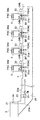
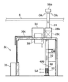
以下、本発明の好適な実施の形態について、添付図面に基づいて詳細に説明する。図1は、本発明の空調システムの一実施例を示す全体構成図であり、図中、符号2は高速道路等の有料道路脇に設置された管理事務所、符号3は道路の走行車線5の横に設置された料金収受用のブースである。ブース3は、図1に示したように複数(2箇所以上)設置されるのが一般的であるが、車両の通行量の少ない地域等に於いては1箇所のみの場合もある。
DESCRIPTION OF EXEMPLARY EMBODIMENTS Hereinafter, preferred embodiments of the invention will be described in detail with reference to the accompanying drawings. FIG. 1 is an overall configuration diagram showing an embodiment of an air conditioning system according to the present invention. In the figure,
管理事務所2には、外気取入口21、外気取入口21から取り入れられた新鮮外気(OA=Outdoor Air)を清浄化する空気清浄機(OAC)23、空気清浄機23やブース3内設置機器の出力制御や、各種の警報出力を行う制御盤25が備えられている。
The
外気取入口21は、ガラリや網目状カバー等で構成され新鮮外気を導入する。外気取入口21は、ブース3の遠方に設置されており、排気ガス等による汚染度の低い新鮮外気を導入することが可能である。外気取入口21は、空気清浄機23と一体化され設置されている場合もある。
The
空気清浄機23は、本実施例では、床置型オゾン触媒方式で、オゾンの分解作用により外気に含まれる排気ガス等の汚染空気を脱臭、殺菌し、同時にMOハニカム触媒でオゾンを脱臭し、MCハニカム触媒で余剰オゾンやNOx、SOx等の酸性ガスを吸収除去する。
In the present embodiment, the
更に、空気清浄機23にはオゾンセンサ(図示せず)が内蔵され、このセンサがオゾン濃度を監視し、所定量(例えば0.05ppm)以上のオゾンを検出すると放電を停止し環境基準を遵守する仕組みが採用されている。この他、空気清浄機23は、抗菌・抗ウィルスフィルター、中性能フィルター、イオン集塵機能等を備えていてもよい。
Further, the
更に、本実施例に於ける空気清浄機23はシロッコファン等の送風機23aを備えており、清浄化された新鮮外気が、地下に埋設されたダクト27を介して各ブース3に所定量(図1に於いては2ブースに600m3/h)供給されるようになっている。
Further, the
尚、交通量の少ない有料道路や外気環境の良い場所に於いては、空気清浄機23に代えて、フィルター機能を有するフィルターボックス及び送風機23aのみの構成としてもよい。又、空気清浄機23又はフィルターボックスは、後述する各ブース3に個別に備えられていてもよく、その場合はブース3毎に新鮮外気の清浄化が行われる。
In addition, in a toll road with a small traffic volume or a place where the outside air environment is good, instead of the
制御盤25は、本実施例では壁掛式であり、空気清浄機23の制御も行っている。制御盤25には、管理事務所2及びブース3に設置される装置や設備の制御回路が集中化されていてもよく、システムの円滑かつ安全な運転のためインターロック(防御)回路や、安全回路、異常信号・警報出力回路(例えば、空気清浄機23のフィルターの目詰まりを検出する差圧スイッチ等からの検出信号に基づいて警報出力を行う回路)等が組み込まれていてもよい。
The control panel 25 is a wall-hanging type in this embodiment, and also controls the
更に、制御盤25によりインバータ制御を行えば、周囲状況に応じた新鮮外気の清浄化、給気量の最適化を行うことが出来、又、無駄な消費電力の削減を図ることが出来る。 Further, if inverter control is performed by the control panel 25, fresh outside air can be cleaned and the amount of air supplied can be optimized according to the surrounding conditions, and wasteful power consumption can be reduced.
ダクト27は、管理事務所2及びブース3の地中に埋設され、管理事務所2から全てのブース3に接続されており、清浄化された新鮮外気を各ブース3に供給するための経路を構成する。
The
ダクト27は、本実施例では薄型塩ビ管で構成され、ブース数や給気量に応じて管径が異なる。例えば、ダクト27の内、図1のAで示された部分は、直径200mmの塩ビ管で構成されているが、Bで示された部分は、Aの部分の管径より小さく、直径150mmの塩ビ管が用いられている。これは、全てに渡って同径のダクトを配管すると、送風源から遠くなるに従って風がダクトを通る時に生じる抵抗により風量が低下することに伴い、全てのブース3に均一の風量を供給するためにダクトの径を順次小さくしていく必要があるためである。
In this embodiment, the
ブース3への給気方法は、図1に示したようなダクト27を介してのみならず、図2に示すような地下道29を介してでもよい。図2は、本発明の空調システムの他の実施例を示す全体構成図であり、ブース3は4箇所設置されている。図1と図2の主な相違点は、ダクト27又は地下道29の有無、空気清浄機23の形態の相違(図2に於いては点吊型)、空気清浄機23や送風機23aの送風量の相違であり、空調システムの基本構成は変わらないため、同一機能を有する装置、手段には、図1、図2ともに同一符号を付している。
The air supply method to the
図2に示す空調システムの場合、密閉状態が維持された地下道29の管理事務所2側には、ダクト27aを介して外気取入口21と接続された空気清浄機23、空気清浄機23や送風機23a等を制御する制御盤25が設置されており、空気清浄機23によって清浄化された新鮮外気は、送風機23aから地下道29を通って各ブース3に供給される。このような地下道29を利用した給気方法では、地下道29そのものがダクトの役目を果たすため、図1に示したようなダクト27の配管が不要となる。
In the case of the air conditioning system shown in FIG. 2, an
尚、図1、図2に示した給気方法の他、図2に示した地下道29内に図1に示したようなダクト27を設置し、ダクト27を介して給気する場合もある。
In addition to the air supply method shown in FIGS. 1 and 2, a
いずれにせよ、本発明の空調システムでは既設のダクト27や地下道29をそのまま利用することも可能である。
In any case, in the air conditioning system of the present invention, the existing
次に、ブース3は、ブースターファン(BF)31、ブース内ダクト32、ブース3内給気(SA=Supply Air)用の外気吹出口33、空調機34とにより構成される。
Next, the
ブースターファン31は、ダクト27又は地下道29との接続口に設けられ、図2に示すように、新鮮外気を取り入れる外気取入口31aを有し、図1に於いてはダクト27と、図2に於いては地下道29と連通している。外気取入口31aから取り入れられた新鮮外気は、ブースターファン31によって所定量がブース内ダクト32に送り込まれる。
The
各ブース3への新鮮外気の供給量は、1ブース(室内容積約7m3)当り300m3/h以上とすることが日本道路公団仕様で定められており、当然のことながら、ブースターファン31は少なくとも規定量の新鮮外気をブース3に送り込むことが出来る性能を有している必要があり、本実施例のブースターファン31の容量は、300m3/h×100Pa×150φ以上である。
The supply amount of fresh outside air to each
尚、ブース3への給気量が定められているのは、以下の理由によるものである。すなわち、ブース3内料金収受員は、有料道路への進入車両からの料金収受のため、1年を通じほぼ全日かつ終日に渡り、ブース3の窓や扉を開放した状態で当該作業を行っているが、車両から排出される排気ガスによりブース3周辺の空気は大変汚染されており、料金収受員の健康面の安全確保が必要とされる。そこで、ブース3内に所定量の新鮮外気を導入することにより、ブース3内の見かけ上の気圧も下げられ、汚染空気の侵入を防止し、料金収受員の健康が維持されるのである。
The air supply amount to the
尚、本発明の空調システムに於いて、上述したブースターファン31とブース内ダクト32についても既設のものを利用することが可能である。
In the air conditioning system of the present invention, the
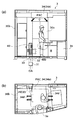
ここで、外気吹出口33と空調機34については図3を参照しながら説明する。図3は、図1、図2に示したブース3内の詳細構成図であり、図3(a)は側面図、図3(b)は上面図である。
Here, the
図3に示すブース3は、縦1.6m、横2.8m、高さ2.5m、容積10.8m3で、料金収受員約一人分の着席及び起立が可能な収容スペースを有している。又、料金収受員が進入車両から料金収受を行うための窓30a、料金収受員がブース3に出入りするための扉30bが設けられており、いずれも年間を通じてほぼ全日、かつ終日に渡り開放された状態となっている。
図3中、符号35は、排気ガス等の汚染空気がブース3内に侵入するのを防止するための飛散送風機である。尚、汚染空気のブース3内侵入防止策としては、飛散送風機35の他、エアカーテン(図示せず)等も用いられる。
In FIG. 3,
図3に示す外気吹出口33は、ブースターファン31及びブース内ダクト32を介して送り込まれた新鮮外気をブース3の下方側から放出させる。本実施例では、外気吹出口33は、料金収受員の後方部に配置されている。
The
更に、外気吹出口33の近傍には、冬季等の低温時に稼動して新鮮外気を暖気に変換するヒータ42(図3には示さず)が配置されている。これにより、寒冷時には、新鮮外気がヒータ42によって暖められて、床面の外気吹出口33から排出されるので、料金収受員は足元から身体を暖めることが出来、寒冷時以外には、ブースターファン31を介して送り込まれた新鮮外気がそのまま外気吹出口33から排出される。
Further, a heater 42 (not shown in FIG. 3) that operates at a low temperature such as in winter and converts fresh outside air into warm air is disposed near the
尚、ブース内ダクト32が、ブース3の床面に対して垂直にブースターファン31から天井部までの間、既に配管されている場合には、ブース内ダクト32の床面近傍に、ブース3室内に面する外気吹出口33を嵌め込み可能な開口部を設け、ブース内ダクト32内にヒータ42を介装させてもよい。ブース内ダクト32とブース3室内との間に壁が介装されている場合には、壁にも当該開口部と同位置に開口部を設け、外気吹出口33をブース3室内に対して露出させる必要がある。
If the
図3に示す空調機34は、夏季等の高温時に稼動する冷房機能を少なくとも有し、冷暖気吹出口34dをブースの上方側に有している。これにより、暑い時には、上方から冷気が排出され、かつ、床面から特別な冷暖気調整が施されていない新鮮外気が排出されるので、これら冷気と新鮮外気とが混合され、冷気が足元に滞留しにくくなり、快適なブース内環境が維持される。
The
本実施例に於ける空調機34は、図1に示すように、室内機34aと室外機34bが分離しており、冷暖気吹出口34dを有する室内機34aはブース3内天井に、室外機34bはブース3の外脇に設置される。室内機34aと室外機34bは冷媒管(R)34cを介して接続されているが、これらが一体となった空調機であってもよい。
As shown in FIG. 1, the
空調機34は、個々のブース3に備えられ、個々のブース3の空気調整を行う能力を有していればよいので、家庭用のルームエアコンや、業務用のパッケージエアコンでもよい。
The
本実施例では、市販のカセットタイプのヒートポンプ式パッケージエアコンが使用されており、室内機34aには車両進入方向の前後2方向の冷暖気吹出口34dを備えており、個別調整が可能なコントローラ(図示せず)が付属している。
In the present embodiment, a commercially available cassette type heat pump type package air conditioner is used, and the
本実施例に於ける空調機34の冷房能力は4.5kW、暖房能力は5.0kW、圧縮機出力は1.0kWであるが、ブース3の容積や設置場所の気候、稼動率等に応じて適宜態様の変更も可能であり、冷暖房機能の他、除湿・加湿・清浄機能等を有していてもよく、冷媒の使用有無も問わない。温度・風量・風向等の調整を行うためのコントローラの態様についても限定せず、リモコンタイプ、壁面固定タイプでもよい。
In this embodiment, the cooling capacity of the
又、詳細は後述するように、ブース3の設置地域によっては冬季はヒータ42の稼動のみで耐寒可能であるため、その場合の空調機34は冷房専用の空調機であってもよい。もちろん、冷暖房の両方が可能な市販の空調機を用い、暖房の機能を使用しない、といった使用方法でもよい。これらの場合、冷暖気吹出口34dは冷気吹出口となることは言うまでもない。
Further, as will be described in detail later, depending on the area where the
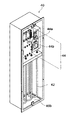
図5は外気吹出口33の外観図である。本実施例に於ける外気吹出口33は、ヒータ42を内部に収容する筐体40の一側面に形成されている。この筐体40を、図3に示すように、ブースターファン31及びブース内ダクト32と連通するようにブース3内の下方側に設置すればよい。ヒータ42を外気吹出口33付きの筐体40に収容することにより、外気吹出口33とヒータ42が一体化され、ヒータ42が外気吹出口33の直近に設けられヒータ42で変換された暖気が効率的に外気吹出口33から排出されるとともに、これらのブース3内設置や持ち運びが容易となる。
FIG. 5 is an external view of the
外気吹出口33は、本実施例では、図5に示したように風向を変えることが可能な可変式吹出ガラリで構成されているが、ガラリの他、適正量の暖気排出が可能な網目状カバーで構成されてもよい。
In the present embodiment, the
又、外気吹出口33が形成された当該一側面には、側面パネル40aが形成されており、料金収受員が操作可能なように、ヒータ42の内部回路への作動電力の入切を行う電源スイッチ44a、排出される暖気の温度を設定する温度設定スイッチ44bが露出している。
Further, a
図6は外気吹出口33と一体化された側面パネル40aを取り外した状態の筐体40の内部構造図である。外気吹出口33の筐体40内部には、ヒータ42が収容されており、側面パネル40aの内部には、電源スイッチ44aや温度設定スイッチ44bを含む制御部44が収容されている。
FIG. 6 is an internal structure diagram of the
又、外気吹出口33が形成された側面以外の筐体40側面のいずれかは、ブースターファン31から新鮮外気を直接取り入れるために開口しており連通口40bを形成している。本実施例では、筐体40の上下面は、ブース内ダクト32の断面形状に合わせて作られており、下面に設けられた連通口40bが新鮮外気の取入口を兼用しているので、ブース内ダクト32が既設されている場合にも、筐体40をブース内ダクト32に介装させることが可能である。又、ブース内ダクト32の断面積相当が開口していることにより、ブースターファン31から送り込まれた新鮮外気を漏れなく取り入れることが出来る。
Any one of the side surfaces of the
ヒータ42は、筐体40内の、外気吹出口33に対向する位置に収容されている。本実施例に於けるヒータ42はシーズヒータであり、公称出力3kW、9〜25℃degの範囲での暖気の温度調節が可能である。尚、5m3/minの風量の空気を3kWで暖めると当該空気の温度は約25℃上昇する。
The
シーズヒータは、コイル状に巻いた発熱線を金属パイプの中に挿入し、絶縁粉末を充填した抵抗発熱体であり、熱触媒を介さずに新鮮外気を暖気に変換するため熱変換効率が高く空気が汚れない、又、高絶縁の絶縁粉末の使用により安全、長寿命、形状加工容易等というメリットがある。尚、ヒータ42は、シーズヒータのような抵抗発熱体の他、石英管、ニクロム線、半導体等種々の発熱体で構成されてもよい。
A sheathed heater is a resistance heating element filled with insulating powder by inserting a coiled heating wire into a metal pipe, and has high heat conversion efficiency because it converts fresh outside air into warm air without using a thermal catalyst. The air does not get dirty, and the use of insulating powder with high insulation has advantages such as safety, long life, and easy shape processing. The
制御部44には、電源スイッチ44aや温度設定スイッチ44bからの入力を受けてヒータ42の発熱を制御するヒータ制御部の他、外部とのインターフェースとして制御入力及び制御出力を可能とする端子台や、他の機器に電力を供給するための電力取出部(アウトレット)等が設けられている。本実施例の制御部44は、電子温度調整器による電源回路遮断機能、温度ヒューズによる電源回路遮断機能を有している。更に、ヒータ42の制御を、電子温度調整器によるPID制御により行うことにより、安定に、かつ、きめ細かい温度管理が可能となる。
In addition to the heater controller that receives heat input from the
制御部44内に設けられた端子台には、ヒータ42の外部に設置された夏季・冬季切替スイッチから出力された信号線やブースターファンスイッチから出力された信号線が接続され、これら信号線が制御部44に入力されてもよい。これにより、例えば、夏季・冬季切替スイッチが夏季側になっている場合には、ヒータ42には電力供給がなされず、ブース内ダクト32から供給された新鮮外気はそのまま外気吹出口33を通過して、ブース3室内に導入される。又、ブースターファンスイッチがOFF側になっている場合には、そもそもブース3内に新鮮外気が供給されない状態であるので、安全のためヒータ42の動作を停止させる。
The signal block output from the summer / winter selector switch installed outside the
図7は、室内機34aと室外機34bが一体となった空調機34が設置されたブース3bの内部詳細構成図を示している。尚、先の実施例と同一機能を有する装置、手段には、先の実施例と同一符号を付し、詳細説明を省略することとする。
FIG. 7 shows an internal detailed configuration diagram of the
図7に示す空調機34はブース3bの平屋根30cの上に設置され、空調機34とブース3b室内を連通させるように介装されるチャンバー38が、室内機34aの冷暖気吹出口34d兼室内空気取入口となる。チャンバー38は、手動開閉式の他、ブース3b室内に設置された制御ボックス(図示せず)での制御が可能なように電磁開閉式でもよい。
The
給気方式は、図1に示した空調システムに於ける方式と同様であり、管理事務所2側のフィルター23bによって清浄化された新鮮外気(OA)が給気ファン23cによって地下に埋設されたダクト27を介して送風され、ブースターファン31によってブース内ダクト32に送り込まれた後、ブース内ダクト32に介装された筐体40の底部連通口40bを介して外気吹出口33からブース3b内に供給される。
The air supply method is the same as that in the air conditioning system shown in FIG. 1, and fresh outside air (OA) purified by the
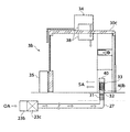
図8は、ブース内詳細構成図の他の一例を示すブース3cである。尚、先の実施例と同一機能を有する装置、手段には、先の実施例と同一符号を付し、詳細説明を省略することとする。 FIG. 8 is a booth 3c showing another example of the detailed configuration diagram in the booth. It should be noted that devices and means having the same functions as those of the previous embodiment are denoted by the same reference numerals as those of the previous embodiment, and detailed description thereof is omitted.
図8に示すブース3cの平屋根30cの上には、室内機34aと室外機34bが一体化された空調機34が設置され、図7同様、チャンバー38を介して室内機34aの冷暖気吹出口34d兼室内空気取入口とブース3c室内とが連通している。
On the
但し、図8に示すブース3c内への給気は、ダクト27や地下道29を介してではなく、ブース3c毎に設置された煙突型ダクト39を介して行われる。煙突型ダクト39は、複数連立するブース3の上方を横断するように設置された大屋根6を貫通しており、天頂部39aは、大屋根6を貫通して上空遠方まで伸びている。これにより、天頂部39aから排気ガス等に汚染されていない新鮮外気(OA)をブース3内に導入することが可能である。
However, the supply of air into the booth 3c shown in FIG. 8 is performed not via the
煙突型ダクト39の天頂部39aの開口部から導入された新鮮外気は、ブース3cの平屋根30cの上に設置され、煙突型ダクト39と連通しているフィルター23bによって清浄化された上で、給気ファン23c(ブースターファン31と同じ)によりブース3c内の壁面に沿って設置されたブース内ダクト32に所定量送風される。
Fresh fresh air introduced from the opening of the
ブース内ダクト32の終端である最下部には、ヒータ42及び外気吹出口33が一体化された筐体40が介装されている。ブース内ダクト32のブース内壁面側には開口部が設けられ、この開口部からは外気吹出口33がブース3c室内に露出している。更に、筐体40の上面には、ブース内ダクト32との連通口40bが設けられており、連通口40bを介して外気吹出口33からブース3c内に新鮮外気が供給される。
A
ブース3c内には制御ボックス(図示せず)が設置されており、給気ファン23cを制御して給気量を調整することが可能である。制御ボックスには、ヒータ42や空調機34の制御回路が含まれていてもよい。尚、制御ボックスは、管理事務所2側に設けられていてもよい。
A control box (not shown) is installed in the booth 3c, and the air supply amount can be adjusted by controlling the
尚、図7及び図8で用いられている空調機34は、冷房能力4.0kW、圧縮機出力1.1kW、冷却器ファン形式がシロッコファン、凝縮器ファン形式がプロペラファンの冷媒式冷房専用スポットエアコンであるが、冷暖房の両機能を備えた家庭用ルームエアコンや業務用パッケージエアコンであってもよい。
The
図9は、ブース内詳細構成図の他の一例を示すブース3dである。尚、先の実施例と同一機能を有する装置、手段には、先の実施例と同一符号を付し、詳細説明を省略することとする。
FIG. 9 is a
図9に示すブース3dの平屋根30cの上には、煙突型ダクト39及び煙突型ダクト39と連通するフィルター23bや給気ファン23cが設置され、ブース3d内への新鮮外気(OA)の給気がこの煙突型ダクト39及びブース内ダクト32を経由して、筐体40の一側面に形成された外気吹出口33から筐体40の上面連通口40bを介して行われる点は図8に示したブース3cと同様である。
A
図9に示したブース3dと、図8に示したブース3cとの構成上の相違は、図9の空調機34が平屋根30cの上に設置された室外機34bとブース3d室内の壁面に設置された室内機34aの分離タイプである点である。尚、室内機34aと室外機34bは冷媒管(R)34cで接続されている。図9に示したように、室内機34aと室外機34bを分離することによって、各々を任意に選択して自由に組合わせることが出来、いずれかが故障した場合にも迅速に修理の対応がしやすい。又、一体型の空調機34よりも、室内機34aの冷暖気吹出口34dの位置や向きを比較的調整しやすい。但し、本考案に於ける空調効果やイニシャルコスト、ランニングコストは、図8、図9ともほとんど変わらないので、ブース周囲の環境や好み等に応じて、いずれを選択しても構わない。
The difference in configuration between the
尚、図9に示したブース3dで使用されている空調機34は、冷房能力2.8kW、暖房能力3.6kW、圧縮機出力750Wの冷暖房用壁掛形ルームエアコンである。室内機34a側の送風はラインフローファンによって行われ、冷房時風量は670m3/h、暖房時風量は750m3/hである。室外機34b側の送風はプロペラファンによって行われ、風量は冷房時、暖房時ともに1765m3/hである。
The
又、寒冷地等の特殊地域を除く一般的な地域に於いては、空調機34として、上記冷暖房用壁掛形ルームエアコンの他、冷房専用壁掛形ルームエアコンを用いることも可能である。冷房専用壁掛形ルームエアコンの仕様の一例は、冷房能力2.2kW、圧縮機出力650W、室内機34aの送風方式はラインフローファンで風量は480m3/h、室外機34bの送風方式はプロペラファンで風量は1680m3/hであるが、必ずしもこの仕様に限定されることはない。
In a general area excluding special areas such as cold districts, the
以下、上記構成による空調システムの各種運転モードについて、図3、図4に示すブース3内詳細構成図と、図10に示す従来のブース3内詳細構成図とを対比させながら、詳細に説明する。
Hereinafter, various operation modes of the air conditioning system having the above configuration will be described in detail while comparing the detailed configuration diagram in the
尚、従来の空調システムに於けるブース3の詳細構成図は、図10に示す通りである。従来の空調システムの主な特徴は、(1)ヒータ42がないこと、(2)空調方式は中央熱源方式を採用しており、管理事務所2側の外気処理装置で冷気、暖気に調整された新鮮外気がブース内ダクト32を介して天井給気口36からブース3内に排出され、ブース3個別には4方向の冷暖気吹出口34dを有する補助空調機37を備えていることである。
In addition, the detailed block diagram of the
尚、図10に示した補助空調機37は、冷房能力3.6kW、暖房能力4.0kW、圧縮機出力1.3kWのパッケージエアコンであり、管理事務所2側の外気処理装置は、2箇所のブース3に対応可能な能力を有し、外気処理送風量600MCH、冷房能力14.0kW、暖房能力16.0kW、圧縮機出力3.5kWを有する大型エアコンである。
The
(1)冬季等の低温時に於ける暖房運転モード
図10に示す従来の空調システムに於ける暖房時の空気の流れは以下の通りである。まず、管理事務所2の外気取入口21から取り入れられた新鮮外気(OA)は、管理事務所2内にある外気処理装置によって暖気に調整され、ダクト27を介して送風され、ブース3に設けられたブース内ダクト32を通って天井給気口36から排出される。
(1) Heating operation mode at low temperature such as in winter The air flow during heating in the conventional air conditioning system shown in FIG. 10 is as follows. First, fresh outside air (OA) taken from the
この場合、図10に示されるように暖気の排出口は天井のみであるため、外気処理装置側で強運転を行うと、料金収受員の頭に直接暖気があたり、これが不快感、頭痛等の原因となる。逆に、弱運転を行うと、料金収受員の足元まで暖気が届かず暖房効果が得られないため、結局はブース3個別に補助空調機37を稼動せざるを得ず、ランニングコストが増大する。更に、補助空調機37から吹き出される暖気の向きは4方向に渡っており、特に、ブース3の窓30aに向かって吹き出す暖気はブース3外に吹き出すため、無駄が多かった。
In this case, as shown in FIG. 10, the warm air outlet is only on the ceiling, so if the outside air treatment device is operated strongly, warm air directly hits the head of the toll collector, which causes discomfort, headaches, etc. Cause. On the other hand, if a weak driving is performed, the warm air does not reach the feet of the toll collector and the heating effect cannot be obtained. Consequently, the
そこで、本考案の空調装置では、図3に示したように、ブース3の床面に、ブース内ダクト32と連通する外気吹出口33が側面に形成された筐体40を設置し、更に、筐体40内の外気吹出口33に対向する位置にヒータ42を収容した。又、空調機34の冷暖気吹出口34dを車両進入方向の前後2方向とした。
Therefore, in the air conditioner of the present invention, as shown in FIG. 3, a
この構成により、管理事務所2で取り入れられた新鮮外気は、空気清浄機23によって清浄化された後、地下のダクト27からファンを介して各ブース3のブース内ダクト32に供給されるとともに、ブース内ダクト32との連通口40bから導入され、ヒータ42によって暖められ、熱損失の発生なく暖気として、十分かつ必要な量だけ足元近傍の外気吹出口33からブース3内に吹き出す。これにより、料金収受員は、足元から直接的に身体を暖めることが出来、汚染外気からも保護される。
With this configuration, fresh outside air taken in by the
特に本実施例では、ブース3内の窓30aに対向する壁面の床上にヒータ42が設置されているので、1日の内の7〜8割程度が窓口での立ち業務となる料金収受員にとっても快適な環境が維持される。
In particular, in the present embodiment, since the
又、新鮮外気が、従来のようにブース3の天井裏に介さず、地下から直接足元に送風されるので、空気の漏れや逃げがなく規定通りの新鮮外気をブース3内に供給することが出来、又、ダクトを天井裏まで配管する必要がなくなる。
Also, fresh outside air is blown directly from the basement to the feet without going through the ceiling of the
更に、空調機34を稼動させることで、室内機34aの室内空気取入口(図示せず)から取り入れられたブース3内の空気が暖気に変換され、2箇所の冷暖気吹出口34dより高速な風がブース3内に吹き出す。熱交換された空気は室外機34bから排出される。これにより、特にヒータ42の発熱容量が小さい場合や寒冷地に於いても、料金収受員の身体全体を十分に暖めることが可能となる。
Furthermore, by operating the
尚、一般的な容量のヒータ42の使用時や寒冷地以外の土地では、空調機34を稼動させなくてもヒータ42の稼動のみで快適な暖房効果を得ることが可能である。
It should be noted that a comfortable heating effect can be obtained only by operating the
ヒータ42と空調機34の併用が必要であったとしても、空調機34は従来よりも弱い暖房強度で十分に耐寒可能であり、又、コントローラによって、ブース3個別に空調機34の調整が可能であるから、従来中央熱源方式により外気処理装置で行われていた暖気の調整よりも熱変換効率が高く、ダクト27や地下道29を通過する際の熱損失も発生しないので、ランニングコストは安くなる。
Even if it is necessary to use both the
いずれにせよ、冬季に於ける空調機34は、ヒータ42の暖房効果の補助的役割を果たせば十分であるから、従来のようにブース3専用に設計された空調機や外気処理装置を使用する必要はなく、市販のルームエアコンやパッケージエアコンを使用することが出来、地域や料金収受員の好みに応じて空調機選択の幅が広がる。
In any case, since it is sufficient for the
(2)夏季等の高温時に於ける冷房運転モード
図10に示す従来の空調システムに於ける冷房時の空気の流れは以下の通りである。まず、管理事務所2の外気取入口21から取り入れられた新鮮外気(OA)は、管理事務所2内にある外気処理装置によって冷気に調整され、ダクト27を介して送風され、ブース3に設けられたブース内ダクト32を通って天井給気口36から排出される。
(2) Cooling operation mode at high temperature such as in summer The air flow during cooling in the conventional air conditioning system shown in FIG. 10 is as follows. First, fresh outside air (OA) taken from the
この場合、冷気はブース3の下方に滞留しやすく、これが料金収受員の足元の冷え過ぎの原因となる。更に中央熱源方式では、外気処理装置で処理された冷気は、ダクト27や地下道29を通過する際の熱損失に伴いブース3に供給される時点では地上の外気温とほとんど変わらない状態となるため、その分だけ外気処理装置側で大幅に低温化させた冷気に調整する必要があり、更には、ブース3個別に設けられた補助空調機37の併用稼動が必要であり、ランニングコストが増大するばかりか、省エネに貢献していなかった。
In this case, the cold air is likely to stay below the
そこで、本発明の空調システムでは、図4に示したように、暖房時に使用するヒータ42の稼動を行わず、ブースターファン31からブース内ダクト32に送り込まれた新鮮外気を筐体40の連通口40bを介して外気吹出口33からブース3室内に送風し、更にブース3個別に設置された空調機34で、室内機34aの室内空気取入口から取り入れられたブース3内の空気を冷気に変換し、天井の冷暖気吹出口34dからブース3内に吹き出すようにした。
Therefore, in the air conditioning system of the present invention, as shown in FIG. 4, the
この構成により、地下のダクト27、ブース内ダクト32を経由して供給された新鮮外気は、十分かつ必要な量だけ、外気吹出口33からブース3内に吹き出し、空調機34はこの空気を利用して料金収受員の設定した温度、風量、風向で、天井から冷気を排出する。床面からは冷暖調整がされていない新鮮外気が排出されるので、新鮮外気と冷気とが混合されて快適なブース3内環境が維持され、又、足元の冷え過ぎを防止することが出来る。
With this configuration, fresh and fresh air supplied via the
以上のように、本発明の空調システムは、外気吹出口33を介してブース内に十分かつ必要な量の新鮮外気をブース内に供給することが出来、かつ、高温時は天井からの冷気と床面からの新鮮外気との混合により冷気の滞留による料金収受員の足元の冷えを防止し、低温時は料金収受員の足元から直接身体を暖めることが出来、季節を問わず1年を通して快適なブース内環境が維持される。
As described above, the air conditioning system of the present invention can supply a sufficient and necessary amount of fresh outside air into the booth through the
又、従来のように大容量かつ高価な空調機や外気処理装置を使用する必要がなく、低コストな市販品でも対応可能であり、環境や好みに応じて空調機選択の幅が広がる。 又、ルームエアコンやパッケージエアコンには、コントローラが備えられており、ブース個別に好みの調整を行うことが可能となり、中央熱源方式のように過剰な空調制御を行う必要がなく省エネ及びランニングコストの削減に貢献する。 In addition, it is not necessary to use a large-capacity and expensive air conditioner or an outside air processing device as in the conventional case, and it is possible to cope with a low-cost commercial product, and the range of air conditioner selection is expanded according to the environment and preference. In addition, room air conditioners and packaged air conditioners are equipped with controllers, and it is possible to make individual adjustments for each booth, eliminating the need for excessive air conditioning control unlike the central heat source method, saving energy and running costs. Contributes to reduction.
又、筐体40によって、外気吹出口33とヒータ42とを一体化させることが出来、ブース内設置や持ち運びが容易となる。
Further, the
又、筐体40の上面又は下面が開口して新鮮外気の取入口を兼用しているので、ダクトが既設されているブースへのシステム導入が容易となる。
Further, since the upper surface or the lower surface of the
又、遠方からの新鮮外気を取り入れることにより、排気ガス等による汚染度が低い新鮮外気をブース内に供給することが可能となる。
Further, by taking in fresh outside air from a distance, it becomes possible to supply fresh outside air having a low degree of contamination with exhaust gas or the like into the booth.
以上、本発明の実施例について説明したが、本発明は必ずしも上述した構成及び実施例に限定されるものではなく、各種の変更及び修正が可能であり、かかる変更及び修正についても本発明の特許請求の範囲に属することはいうまでもない。 Although the embodiments of the present invention have been described above, the present invention is not necessarily limited to the configurations and embodiments described above, and various changes and modifications are possible. Needless to say, it belongs to the scope of claims.
又、ここでは、図3、図4の実施例に基づき、ダクト給気方式で、空調機34が室内機34aと室外機34b分離タイプの空調システムの実施例について説明したが、図7で説明した一体型空調機34を用いた空調システムや、図8や図9で説明した煙突型ダクト39による給気方式の空調システムでも、上記同様の実施例となり、同様の作用効果が得られるので、これらの実施例の説明を省略する。
Here, based on the embodiment of FIG. 3 and FIG. 4, the embodiment of the air conditioning system in which the
2:管理事務所
21:外気取入口
23:空気清浄機
23a:送風機
23b:フィルター
23c:給気ファン
25:制御盤
27:ダクト
29:地下道
3:ブース
30a:窓
30b:扉
30c:平屋根
31:ブースターファン
31a:外気取入口
32:ブース内ダクト
33:外気吹出口
34:空調機
34a:室内機
34b:室外機
34c:冷媒管
34d:冷暖気吹出口
35:飛散送風機
36:天井給気口
37:補助空調機
38:チャンバー
39:煙突型ダクト
40:筐体
40a:側面パネル
40b:連通口
42:ヒータ
44:制御部
44a:電源スイッチ
44b:温度設定スイッチ
5:走行車線
6:大屋根
2: Management office 21: Outside air inlet 23:
Claims (9)
ファンを介して送り込まれた前記新鮮外気を前記ブースの下方側から放出させる外気吹出口と、
前記外気吹出口近傍に配置され、冬季等の低温時に稼動して前記新鮮外気を暖気に変換するヒータと、
夏季等の高温時に稼動する冷房機能を少なくとも有し、冷気ないしは冷暖気の吹出口を前記ブースの上方側に有する空調機と
を備えることを特徴とする空調システム。 An air conditioning system that supplies fresh outside air into a toll collection booth provided at a toll gate on a toll road, and adjusts the air in the booth,
An outside air outlet for releasing the fresh outside air sent through a fan from the lower side of the booth;
A heater that is disposed in the vicinity of the outside air outlet, operates at a low temperature such as in winter, and converts the fresh outside air into warm air;
An air conditioning system comprising: an air conditioner having at least a cooling function that operates at a high temperature such as in summer, and having a cold air outlet or a warm air outlet above the booth.
コントローラを備えた、家庭用のルームエアコンないしは業務用のパッケージエアコンである
ことを特徴とする請求項1に記載の空調システム。 The air conditioner
The air conditioning system according to claim 1, wherein the air conditioner is a room air conditioner for home use or a packaged air conditioner for business use provided with a controller.
風向を変えることが可能な可変式ガラリである
ことを特徴とする請求項1又は請求項2に記載の空調システム。 The outside air outlet is
The air-conditioning system according to claim 1 or 2, wherein the air-conditioning system is a variable louver capable of changing a wind direction.
抵抗発熱体から構成されるシーズヒータである
ことを特徴とする請求項1から請求項3のいずれかに記載の空調システム。 The heater is
It is a sheathed heater comprised from a resistance heating element. The air conditioning system in any one of Claims 1-3 characterized by the above-mentioned.
前記外気吹出口が側面に形成された筐体内に収容されている
ことを特徴とする請求項1から請求項4のいずれかに記載の空調システム。 The heater is
The air conditioning system according to any one of claims 1 to 4, wherein the outside air outlet is housed in a housing formed on a side surface.
前記ブース床面に対して垂直に設置され、前記新鮮外気を導入するダクトを備え、
前記筐体は、
上面又は下面が前記ダクトと連通開口し、前記ダクト内に設置される
ことを特徴とする請求項5に記載の空調システム。 The air conditioning system
It is installed perpendicular to the booth floor, and includes a duct for introducing the fresh outside air,
The housing is
The air conditioning system according to claim 5, wherein an upper surface or a lower surface opens to communicate with the duct and is installed in the duct.
前記外気吹出口と連通し、前記ブースの遠方から前記新鮮外気を導入する地下埋設ダクトを備える
ことを特徴とする請求項1から請求項6のいずれかに記載の空調システム。 The air conditioning system
The air conditioning system according to any one of claims 1 to 6, further comprising an underground duct that communicates with the outside air outlet and introduces the fresh outside air from a distance of the booth.
前記外気吹出口と連通し、前記ブースの遠方から前記新鮮外気を導入する地下道を備える
ことを特徴とする請求項1から請求項6のいずれかに記載の空調システム。 The air conditioning system
The air conditioning system according to any one of claims 1 to 6, further comprising an underpass communicating with the outside air outlet and introducing the fresh outside air from a distance of the booth.
前記外気吹出口と連通する煙突型ダクトを備え、
前記煙突型ダクトは、
前記ブースの上方に設置された大屋根を貫通しており、前記大屋根の上方から前記新鮮外気を導入する開口部を有する
ことを特徴とする請求項1から請求項6のいずれかに記載の空調システム。
The air conditioning system
Comprising a chimney-type duct communicating with the outside air outlet;
The chimney duct is
It has penetrated the big roof installed above the booth, and has an opening part which introduces the fresh fresh air from the upper part of the big roof. The claim according to any one of claims 1 to 6 characterized by things. Air conditioning system.
Priority Applications (1)
| Application Number | Priority Date | Filing Date | Title |
|---|---|---|---|
| JP2003375544A JP2005140366A (en) | 2003-11-05 | 2003-11-05 | Air conditioning system |
Applications Claiming Priority (1)
| Application Number | Priority Date | Filing Date | Title |
|---|---|---|---|
| JP2003375544A JP2005140366A (en) | 2003-11-05 | 2003-11-05 | Air conditioning system |
Publications (2)
| Publication Number | Publication Date |
|---|---|
| JP2005140366A true JP2005140366A (en) | 2005-06-02 |
| JP2005140366A5 JP2005140366A5 (en) | 2006-10-26 |
Family
ID=34686888
Family Applications (1)
| Application Number | Title | Priority Date | Filing Date |
|---|---|---|---|
| JP2003375544A Pending JP2005140366A (en) | 2003-11-05 | 2003-11-05 | Air conditioning system |
Country Status (1)
| Country | Link |
|---|---|
| JP (1) | JP2005140366A (en) |
Cited By (3)
| Publication number | Priority date | Publication date | Assignee | Title |
|---|---|---|---|---|
| KR100717202B1 (en) | 2005-10-06 | 2007-05-15 | 주식회사 휴먼센추리 | Toll Booth for Road |
| CN106369682A (en) * | 2016-10-27 | 2017-02-01 | 苏州艾尔新净化科技有限公司 | Air purification system for toll booth |
| JP2017106676A (en) * | 2015-12-10 | 2017-06-15 | ハイウェイ・トール・システム株式会社 | Air conditioning system |
-
2003
- 2003-11-05 JP JP2003375544A patent/JP2005140366A/en active Pending
Cited By (3)
| Publication number | Priority date | Publication date | Assignee | Title |
|---|---|---|---|---|
| KR100717202B1 (en) | 2005-10-06 | 2007-05-15 | 주식회사 휴먼센추리 | Toll Booth for Road |
| JP2017106676A (en) * | 2015-12-10 | 2017-06-15 | ハイウェイ・トール・システム株式会社 | Air conditioning system |
| CN106369682A (en) * | 2016-10-27 | 2017-02-01 | 苏州艾尔新净化科技有限公司 | Air purification system for toll booth |
Similar Documents
| Publication | Publication Date | Title |
|---|---|---|
| KR100628205B1 (en) | air-conditioner system with ventilation and control method | |
| US20160298863A1 (en) | Air Purification Device With Ozone And Fine Dust Cleaning | |
| CN102705912B (en) | Personalized environment control system for expressway toll booth | |
| US6938434B1 (en) | Cooling system | |
| KR101280661B1 (en) | Indoor unit with hybrid air condition mode, hybrid air condition system having the same | |
| JPH10274425A (en) | Air conditioner with ventilating function and ventilation air conditioning system using air conditioner thereof | |
| JPH0960981A (en) | Heating apparatus for building | |
| CN208442986U (en) | Intelligent aeration air-conditioning system applied to Environmental Control System of Metro | |
| US5913723A (en) | Process and apparatus for air conditioning and/or heating, especially for apartment buildings | |
| DE102006001724A1 (en) | Solid heat exchanger structure is used in building walls to recover heat energy when air exchange is as part of climate control | |
| JP2005140366A (en) | Air conditioning system | |
| JP3101423U (en) | Air conditioner | |
| JP2006105422A (en) | Ventilating device and building | |
| JPH0735419A (en) | Building, utilizing solar heat | |
| US20110263192A1 (en) | Attic Ventilation System | |
| JP2006220325A (en) | Air conditioning structure of building | |
| CN204717850U (en) | Multifunctional air gas disposal all-in-one | |
| KR100506405B1 (en) | Ventilation Apparatus Using Heat Exchange by Double Duct | |
| KR100670668B1 (en) | Supply system of air | |
| US7698903B1 (en) | Energy efficient ventilation system | |
| CN205536160U (en) | Formula of taking a breath air conditioner | |
| JP2989022B2 (en) | Heat recovery type air conditioning equipment | |
| JP2826270B2 (en) | Perimeter air conditioning load reduction system | |
| CN213713336U (en) | System for adjusting physical environment inside building | |
| WO2023017581A1 (en) | Outside air conditioner, outside air conditioning system, and method for operating outside air conditioning system |
Legal Events
| Date | Code | Title | Description |
|---|---|---|---|
| A521 | Written amendment |
Free format text: JAPANESE INTERMEDIATE CODE: A523 Effective date: 20060907 |
|
| A621 | Written request for application examination |
Effective date: 20060907 Free format text: JAPANESE INTERMEDIATE CODE: A621 |
|
| A977 | Report on retrieval |
Effective date: 20090525 Free format text: JAPANESE INTERMEDIATE CODE: A971007 |
|
| A131 | Notification of reasons for refusal |
Free format text: JAPANESE INTERMEDIATE CODE: A131 Effective date: 20090825 |
|
| A02 | Decision of refusal |
Free format text: JAPANESE INTERMEDIATE CODE: A02 Effective date: 20100119 |