JP2005139516A - Plating method and plating device - Google Patents
Plating method and plating device Download PDFInfo
- Publication number
- JP2005139516A JP2005139516A JP2003377719A JP2003377719A JP2005139516A JP 2005139516 A JP2005139516 A JP 2005139516A JP 2003377719 A JP2003377719 A JP 2003377719A JP 2003377719 A JP2003377719 A JP 2003377719A JP 2005139516 A JP2005139516 A JP 2005139516A
- Authority
- JP
- Japan
- Prior art keywords
- plating
- leveler
- plating solution
- dechlorination
- tank
- Prior art date
- Legal status (The legal status is an assumption and is not a legal conclusion. Google has not performed a legal analysis and makes no representation as to the accuracy of the status listed.)
- Pending
Links
- 238000007747 plating Methods 0.000 title claims abstract description 165
- 238000000034 method Methods 0.000 title claims abstract description 28
- RYGMFSIKBFXOCR-UHFFFAOYSA-N Copper Chemical compound [Cu] RYGMFSIKBFXOCR-UHFFFAOYSA-N 0.000 claims abstract description 37
- 229910052802 copper Inorganic materials 0.000 claims abstract description 37
- 239000010949 copper Substances 0.000 claims abstract description 37
- 238000006298 dechlorination reaction Methods 0.000 claims abstract description 32
- QJGQUHMNIGDVPM-UHFFFAOYSA-N nitrogen group Chemical group [N] QJGQUHMNIGDVPM-UHFFFAOYSA-N 0.000 claims abstract description 23
- 150000001875 compounds Chemical class 0.000 claims abstract description 21
- 229920000642 polymer Polymers 0.000 claims abstract description 20
- VEXZGXHMUGYJMC-UHFFFAOYSA-M Chloride anion Chemical compound [Cl-] VEXZGXHMUGYJMC-UHFFFAOYSA-M 0.000 claims abstract description 10
- 239000000460 chlorine Substances 0.000 claims description 35
- -1 chlorine ions Chemical class 0.000 claims description 35
- 239000000758 substrate Substances 0.000 claims description 35
- 229910052801 chlorine Inorganic materials 0.000 claims description 34
- 239000000654 additive Substances 0.000 claims description 12
- 238000012546 transfer Methods 0.000 claims description 10
- 230000000996 additive effect Effects 0.000 claims description 9
- 238000004140 cleaning Methods 0.000 claims description 5
- 230000000382 dechlorinating effect Effects 0.000 claims description 4
- 238000005868 electrolysis reaction Methods 0.000 claims description 3
- 238000009713 electroplating Methods 0.000 claims description 3
- 229910052751 metal Inorganic materials 0.000 claims description 3
- 239000002184 metal Substances 0.000 claims description 3
- 238000001556 precipitation Methods 0.000 claims description 3
- 238000000151 deposition Methods 0.000 claims description 2
- 239000007788 liquid Substances 0.000 abstract 2
- 238000005660 chlorination reaction Methods 0.000 abstract 1
- 239000000243 solution Substances 0.000 description 46
- 239000004094 surface-active agent Substances 0.000 description 13
- 238000012545 processing Methods 0.000 description 12
- 239000002994 raw material Substances 0.000 description 8
- 238000010586 diagram Methods 0.000 description 7
- 230000002829 reductive effect Effects 0.000 description 6
- 239000000463 material Substances 0.000 description 5
- 239000004065 semiconductor Substances 0.000 description 5
- XUIMIQQOPSSXEZ-UHFFFAOYSA-N Silicon Chemical compound [Si] XUIMIQQOPSSXEZ-UHFFFAOYSA-N 0.000 description 4
- IJGRMHOSHXDMSA-UHFFFAOYSA-N nitrogen Substances N#N IJGRMHOSHXDMSA-UHFFFAOYSA-N 0.000 description 4
- 229920002717 polyvinylpyridine Polymers 0.000 description 4
- 229910052710 silicon Inorganic materials 0.000 description 4
- 239000010703 silicon Substances 0.000 description 4
- 238000004090 dissolution Methods 0.000 description 3
- 238000005259 measurement Methods 0.000 description 3
- 229910052757 nitrogen Inorganic materials 0.000 description 3
- KZBUYRJDOAKODT-UHFFFAOYSA-N Chlorine Chemical compound ClCl KZBUYRJDOAKODT-UHFFFAOYSA-N 0.000 description 2
- 230000004888 barrier function Effects 0.000 description 2
- 230000007797 corrosion Effects 0.000 description 2
- 238000005260 corrosion Methods 0.000 description 2
- 230000006866 deterioration Effects 0.000 description 2
- 238000002360 preparation method Methods 0.000 description 2
- 150000003839 salts Chemical group 0.000 description 2
- SQGYOTSLMSWVJD-UHFFFAOYSA-N silver(1+) nitrate Chemical compound [Ag+].[O-]N(=O)=O SQGYOTSLMSWVJD-UHFFFAOYSA-N 0.000 description 2
- 239000000126 substance Substances 0.000 description 2
- LMPMFQXUJXPWSL-UHFFFAOYSA-N 3-(3-sulfopropyldisulfanyl)propane-1-sulfonic acid Chemical compound OS(=O)(=O)CCCSSCCCS(O)(=O)=O LMPMFQXUJXPWSL-UHFFFAOYSA-N 0.000 description 1
- NIXOWILDQLNWCW-UHFFFAOYSA-M Acrylate Chemical compound [O-]C(=O)C=C NIXOWILDQLNWCW-UHFFFAOYSA-M 0.000 description 1
- 229910000838 Al alloy Inorganic materials 0.000 description 1
- VEXZGXHMUGYJMC-UHFFFAOYSA-N Hydrochloric acid Chemical compound Cl VEXZGXHMUGYJMC-UHFFFAOYSA-N 0.000 description 1
- 239000002202 Polyethylene glycol Substances 0.000 description 1
- 229920002873 Polyethylenimine Polymers 0.000 description 1
- 229910004298 SiO 2 Inorganic materials 0.000 description 1
- ATJFFYVFTNAWJD-UHFFFAOYSA-N Tin Chemical compound [Sn] ATJFFYVFTNAWJD-UHFFFAOYSA-N 0.000 description 1
- 239000002253 acid Substances 0.000 description 1
- 229910052782 aluminium Inorganic materials 0.000 description 1
- XAGFODPZIPBFFR-UHFFFAOYSA-N aluminium Chemical compound [Al] XAGFODPZIPBFFR-UHFFFAOYSA-N 0.000 description 1
- 239000007864 aqueous solution Substances 0.000 description 1
- 238000006243 chemical reaction Methods 0.000 description 1
- 238000005530 etching Methods 0.000 description 1
- 150000003840 hydrochlorides Chemical class 0.000 description 1
- 230000010354 integration Effects 0.000 description 1
- 150000002500 ions Chemical group 0.000 description 1
- 150000002894 organic compounds Chemical class 0.000 description 1
- 238000005498 polishing Methods 0.000 description 1
- 229920000083 poly(allylamine) Polymers 0.000 description 1
- 229920001223 polyethylene glycol Polymers 0.000 description 1
- 125000001453 quaternary ammonium group Chemical group 0.000 description 1
- 229910001961 silver nitrate Inorganic materials 0.000 description 1
- 238000003756 stirring Methods 0.000 description 1
- 238000012360 testing method Methods 0.000 description 1
- XLYOFNOQVPJJNP-UHFFFAOYSA-N water Substances O XLYOFNOQVPJJNP-UHFFFAOYSA-N 0.000 description 1
Images


Abstract
Description
本発明は、銅めっき方法、さらに詳しくは、脱塩素処理されたレベラを用いる銅めっき方法およびそれに用いるレベラ、めっき装置に関する。 The present invention relates to a copper plating method, and more particularly to a copper plating method using a dechlorinated leveler, and a leveler and a plating apparatus used therefor.
従来、半導体基板上に配線する回路の形成材料としては、アルミニウムまたはアルミニウム合金が用いられている。しかし、集積度の向上に伴い、より高い導電性を有する材料が求められるようになってきた。そして、この要求を満たす材料として銅が注目され、めっき処理により銅を基板上に形成することが行われている。 Conventionally, aluminum or an aluminum alloy is used as a material for forming a circuit to be wired on a semiconductor substrate. However, as the degree of integration increases, a material having higher conductivity has been demanded. Copper is attracting attention as a material that satisfies this requirement, and copper is formed on a substrate by plating.
そして、均一なめっき膜を得るために、銅めっきにおいては、界面活性剤、不飽和有機化合物、塩素イオン等の種々の添加剤が用いられている。これらの添加剤の中で、塩素イオンは、アノードの溶解と光沢剤の作用を助けるために必要であると言われている(非特許文献1)。また、添加剤の中には、めっき成長を平坦化させるレベラと呼ばれるものがあり、これらのレベラとしては、含窒素高分子化合物が一般的に用いられている。そして、これらの含窒素高分子化合物は、溶解性を向上させるために、3級窒素、または4級窒素の塩として塩酸塩の形態で供給されるものが多く、したがってレベラには、含窒素高分子化合物の他に塩素イオンが含まれることとなる。 In order to obtain a uniform plating film, various additives such as surfactants, unsaturated organic compounds, and chlorine ions are used in copper plating. Among these additives, chlorine ions are said to be necessary to aid the dissolution of the anode and the action of the brightener (Non-patent Document 1). Some additives are called levelers that flatten plating growth, and nitrogen-containing polymer compounds are generally used as these levelers. Many of these nitrogen-containing polymer compounds are supplied in the form of hydrochloride as tertiary nitrogen or a salt of quaternary nitrogen in order to improve the solubility. Chlorine ions will be included in addition to molecular compounds.
上記のように、塩素イオンは、めっき液において重要な役割を果たすものである一方、銅めっきされためっき膜中に塩素イオンが取り込まれた場合、導電性が低下するという問題があった。さらに塩素イオンは、腐食性を有しているため、めっきされた配線の腐食、劣化が生じるという問題もあった。
本発明の課題は、めっき膜中に取り込まれる塩素イオンを減少させることにある。 An object of the present invention is to reduce chlorine ions taken into the plating film.
本発明者らは、後述するように、めっき膜中に取り込まれる塩素イオンは、めっき液に意図して添加される塩素イオンに由来するものではなく、レベラに含まれる微量の塩素イオンに由来するものであることを見出し、かかる知見に基づいて本発明を完成するに至った。 As will be described later, the inventors of the present invention are not derived from chlorine ions intentionally added to the plating solution, but from trace amounts of chlorine ions contained in the leveler. As a result, the present invention has been completed based on this finding.
即ち、本発明は、含窒素高分子化合物を含むレベラを用いる銅めっき方法において、めっき処理前にあらかじめレベラを脱塩素処理することを特徴とする銅めっき方法である。 That is, the present invention is a copper plating method using a leveler containing a nitrogen-containing polymer compound, wherein the leveler is dechlorinated in advance before the plating treatment.
また、本発明は、含窒素高分子化合物1gに対する塩素イオンの重量比が0.1g以下である、含窒素高分子化合物を含む銅めっき用レベラである。 Moreover, this invention is a leveler for copper plating containing the nitrogen-containing polymer compound whose weight ratio of the chlorine ion with respect to 1 g of nitrogen-containing polymer compound is 0.1 g or less.
さらに、本発明は、めっき液調整槽、レベラを脱塩素処理する脱塩素装置、脱塩素処理されたレベラをめっき液調整槽に供給するレベラ供給部、およびめっき処理部を備えためっき装置である。 Furthermore, the present invention is a plating solution adjustment tank, a dechlorination device for dechlorinating the leveler, a leveler supply unit for supplying the dechlorinated leveler to the plating solution adjustment vessel, and a plating apparatus comprising a plating treatment unit. .
また、本発明は、基板表面のシード層上に電気めっきにより金属膜を成膜するめっき装置であって、ロード・アンロード部、基板搬送装置、洗浄ユニット、めっき槽、めっき槽へめっき液を供給するめっき液調整槽、添加剤の濃度を測定する濃度測定部、レベラを脱塩素処理する脱塩素装置、脱塩素処理されたレベラをめっき液へ供給するレベラ供給部を備え、該濃度測定部はめっき液中のレベラ濃度を測定し、その測定された結果に基づいて該レベラ供給部が脱塩素処理されたレベラをめっき液に添加することを特徴とするめっき装置である。 The present invention also relates to a plating apparatus for depositing a metal film on a seed layer on a substrate surface by electroplating, wherein a plating solution is applied to a load / unload unit, a substrate transfer device, a cleaning unit, a plating tank, and a plating tank. A plating solution adjusting tank to be supplied, a concentration measuring unit for measuring the concentration of the additive, a dechlorination device for dechlorinating the leveler, and a leveler supplying unit for supplying the dechlorinated leveler to the plating solution, the concentration measuring unit Is a plating apparatus characterized in that the leveler concentration in the plating solution is measured, and based on the measurement result, the leveler supply unit adds the leveler that has been dechlorinated to the plating solution.
本発明の銅めっき方法、レベラ、またはめっき装置を用いることにより、銅めっき膜中に取り込まれる塩素イオンを減少させることができ、銅めっき配線の腐食、劣化を少なくすることができる。 By using the copper plating method, the leveler, or the plating apparatus of the present invention, chlorine ions taken into the copper plating film can be reduced, and corrosion and deterioration of the copper plating wiring can be reduced.
通常銅めっきに用いられるレベラは、めっき成長を平坦化させるために用いられるものであり、一般的に含窒素高分子化合物を含むものである。ここで用いられる含窒素高分子化合物としては、分子内に窒素分子を含んだ高分子化合物であれば特に制限はないが、例えば、ポリジアルキルアミノエチルアクリレート、ポリジアリルジメチルアンモニウム、ポリエチレンイミン、ポリビニルピリジン、ポリビニルアミジン、ポリアリルアミン、ポリアミンスルホン酸等を挙げることができる。これらの含窒素高分子化合物は、水への溶解性を向上させるために、3級窒素または4級窒素の塩として、塩酸塩の形態とされている。したがって、レベラには、含窒素高分子化合物と塩素イオンが含まれることとなる。 The leveler usually used for copper plating is used for flattening the plating growth and generally contains a nitrogen-containing polymer compound. The nitrogen-containing polymer compound used here is not particularly limited as long as it is a polymer compound containing a nitrogen molecule in the molecule. For example, polydialkylaminoethyl acrylate, polydiallyldimethylammonium, polyethyleneimine, polyvinylpyridine , Polyvinylamidine, polyallylamine, polyaminesulfonic acid and the like. These nitrogen-containing polymer compounds are in the form of hydrochlorides as tertiary nitrogen or quaternary nitrogen salts in order to improve the solubility in water. Therefore, the leveler contains a nitrogen-containing polymer compound and chloride ions.
通常これらのレベラは、水溶液として提供され、その中には、一般的に含窒素高分子化合物が5〜20g/L、塩素イオンが3〜10g/L程度含まれている。 Usually, these levelers are provided as an aqueous solution, which generally contains about 5 to 20 g / L of a nitrogen-containing polymer compound and about 3 to 10 g / L of chlorine ions.
そして、これらのレベラをめっき液に添加し、めっき液中に含まれる含窒素高分子化合物が通常5〜20mg/Lとなるように調整される。このとき、レベラに含まれる塩素イオンもめっき液中にキャリーオーバーとして溶解することとなり、その濃度は、通常数mg/Lとなる。 Then, these levelers are added to the plating solution, and the nitrogen-containing polymer compound contained in the plating solution is usually adjusted to 5 to 20 mg / L. At this time, the chlorine ions contained in the leveler are also dissolved in the plating solution as carry-over, and the concentration is usually several mg / L.
一方、銅めっきに用いられる他の添加剤として、塩素イオンがある。この塩素イオンは、アノードの溶解と光沢剤の作用を助けるために必要であると言われており、めっき液中に通常40〜80mg/L添加される。 On the other hand, there is a chlorine ion as another additive used for copper plating. This chloride ion is said to be necessary to aid the dissolution of the anode and the action of the brightener, and is usually added in an amount of 40 to 80 mg / L in the plating solution.
このように、レベラからのキャリーオーバーとしてめっき液に持ち込まれる塩素イオンの量は、アノードの溶解と光沢剤の作用を助けるためにめっき液に添加される塩素イオンの量と比べ非常に少なく、これらのキャリーオーバーとして持ち込まれる塩素イオンは、めっき処理に影響を及ぼさないと考えられてきた。 In this way, the amount of chlorine ions brought into the plating solution as carryover from the leveler is very small compared to the amount of chlorine ions added to the plating solution to aid the dissolution of the anode and the action of the brightener. It has been considered that the chlorine ions brought in as carry-over of the metal does not affect the plating process.
しかし、後述する実施例に示すように、レベラからのキャリーオーバーとしてめっき液に持ち込まれる塩素イオンが、めっき膜中に優先的に取り込まれることが本発明者らの研究により明らかとなった。したがって、レベラに含まれる塩素イオンを脱塩素処理することにより、めっき膜に取り込まれる塩素イオンを減少させることができることとなる。 However, as shown in the examples described later, it has been clarified by the present inventors that chlorine ions brought into the plating solution as carry-over from the leveler are preferentially taken into the plating film. Therefore, chlorine ions taken into the plating film can be reduced by dechlorinating chlorine ions contained in the leveler.
本発明に用いるレベラの脱塩素処理方法としては、塩素イオンを減少させることができるものであれば特に制限はないが、沈殿または電気分解によるものが好ましい。 The leveler dechlorination treatment method used in the present invention is not particularly limited as long as chlorine ions can be reduced, but precipitation or electrolysis is preferred.
沈殿による脱塩素処理方法としては、例えば、式(I)で示されるように、硝酸銀などの塩素イオンと難溶性の塩を形成する物質をレベラに添加することにより行うことができる。

電気分解による脱塩素処理方法としては、例えば、式(II)で示されるように、アノードにおいて塩素ガスとして除去するものを挙げることができる。
本発明に用いる脱塩素処理後のレベラに含まれる塩素イオンの濃度としては、含窒素高分子化合物1gに対して、0.1g以下であることが好ましく、0.05g以下であることがより好ましく、0.01g以下であることが最も好ましい。塩素イオンの濃度が、含窒素高分子化合物1gに対して0.1gを超えると、めっき膜中に取り込まれる塩素イオンが多くなる場合がある。 The concentration of chlorine ions contained in the leveler after the dechlorination treatment used in the present invention is preferably 0.1 g or less, more preferably 0.05 g or less, with respect to 1 g of the nitrogen-containing polymer compound. And most preferably 0.01 g or less. When the concentration of chlorine ions exceeds 0.1 g with respect to 1 g of the nitrogen-containing polymer compound, chlorine ions taken into the plating film may increase.
また、本発明に用いる脱塩素処理後のレベラに含まれる塩素イオンの濃度としては、1g/L以下であることが好ましい。この濃度を超えると、めっき膜中に取り込まれる塩素イオンが多くなる場合がある。 Moreover, it is preferable that it is 1 g / L or less as a density | concentration of the chlorine ion contained in the leveler after the dechlorination process used for this invention. When this concentration is exceeded, chlorine ions taken into the plating film may increase.
以下、図面を参照して本発明をさらに詳しく説明するが、本発明は、これらの図面に限定されるものではない。 Hereinafter, the present invention will be described in more detail with reference to the drawings. However, the present invention is not limited to these drawings.
本発明のめっき方法、めっき用レベラおよびめっき装置は、主として、半導体基板のめっき面に電解銅めっきを施して、銅層からなる配線を形成するために使用される。まず、ここでめっき工程の一例を図1を参照して説明する。 The plating method, the plating leveler and the plating apparatus of the present invention are mainly used for forming a wiring made of a copper layer by performing electrolytic copper plating on a plating surface of a semiconductor substrate. First, an example of the plating process will be described with reference to FIG.
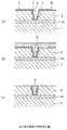
半導体基板Wには、図1(a)に示すように、半導体素子が形成された基板1上の導電層1aの上に、SiO2からなる絶縁膜2が堆積され、リソグラフィ・エッチング技術によりコンタクトホール3と配線用の溝4が形成され、その上にTiN等からなるバリア層5、さらにその上に電解めっきの供給層としてシード層7が形成されている。
The semiconductor the substrate W, as shown in FIG. 1 (a), a contact on a
そして、図1(b)に示すように、前記半導体基板Wの表面に銅めっきを施すことで、基板1のコンタクトホール3および溝4内に銅を充填させると共に、絶縁膜2上に銅層6を堆積させる。その後、化学的機械研磨(CMP)により、絶縁膜2上の銅層6を除去して、コンタクトホール3および配線用の溝4に充填させた銅層6の表面と絶縁膜2の表面とをほぼ同一平面にする。これにより、図1(c)に示すように銅層6からなる配線が形成される。
Then, as shown in FIG. 1B, the surface of the semiconductor substrate W is plated with copper so that the
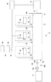
図2は、本発明のめっき装置10の一例を示す図である。図2に示すように、本発明のめっき装置10は、めっき液14を収容するめっき液調整槽12、めっき液調整槽12にそれぞれ、配管15を介してつながる濃度測定部16、配管48を介してつがなるキャリア供給部40、配管58を介してつながる界面活性剤供給部50、配管38を介してつながるレベラ供給部30を備え、さらにレベラ供給部30に配管67を介してつながる脱塩素装置60、脱塩素装置60に配管94を介してつながるレベラ原料槽90を備え、また、濃度測定部16、レベラ供給部30、キャリア供給部40、界面活性剤供給部50にそれぞれつながる制御部18を備え、さらに、めっき液調整槽12と配管100、ポンプ102、フィルタ104、および、配管108、ポンプ106をそれぞれ介してつながるめっき処理部70から構成されている。
また、図2に示すように、レベラ供給部30は、脱塩素されたレベラ34を収容したレベラ槽32、制御部18と接続するポンプ36を、キャリア供給部40は、キャリア44を収容したキャリア槽42、制御部18と接続するポンプ46を、界面活性剤供給部50は、界面活性剤54を収容した界面活性剤槽52、制御部18と接続するポンプ56を、それぞれ備えている。
FIG. 2 is a diagram showing an example of the
Further, as shown in FIG. 2, the
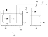
図3は、脱塩素装置60およびレベラ原料槽90の一例を示す図である。図3に示すように、脱塩素装置60は、脱塩素槽62、カソード64、アノード65、撹拌子66を備えている。また、レベラ原料槽90は、レベラ原料92を収容し、配管94、ポンプ96を介して脱塩素槽62とつながっている。
FIG. 3 is a diagram illustrating an example of the
図4は、めっき処理部70の一例を示す図である。図4に示すように、めっき槽76には、めっき液14が収容され、めっき液14には、治具に装着された基板Wとアノード72とが対向して配置され、基板Wとアノードとの間には電源74が接続され、めっき槽76は、配管100および配管108につながっている。
FIG. 4 is a diagram illustrating an example of the
図5は、めっき処理部50の一例の全体平面図である。図5に示すように、このめっき処理部70は、内部に複数の基板Wを収納する四基のロード・アンロード部80と、めっき処理およびその付帯処理を行う四基のめっき施工装置82と、ロード・アンロード部80とめっき施工装置82との間で基板Wの受渡を行う二基の搬送ロボット84、85と、二基のベベル・裏面洗浄ユニット86、86と、一基の膜厚測定装置87と、基板仮置台88とを備えている。ここで、めっき施工装置82は、一部図示を省略するが、各々配管100および108につながっている。なお、図5において、搬送ロボット84、85は、本発明の基板搬送装置を構成する。
FIG. 5 is an overall plan view of an example of the
なお、図2に記載のめっき液調製に関するすべての装置を図5のめっき処理部の枠内に収容し、一体となるように構成してもよい。 Note that all the apparatuses relating to the preparation of the plating solution shown in FIG. 2 may be accommodated in the frame of the plating processing unit shown in FIG.
本発明のめっき装置は、上記のように構成されており、以下その作用について説明する。
レベラ原料槽90に保持されている脱塩素処理前のレベラ原料92は、配管94を介してポンプ96により脱塩素装置60に送られ、脱塩素処理が行われる。脱塩素槽62に投入されたレベラ原料92は、撹拌子66により均一に撹拌される。そして、アノード65、カソード64に電圧が印加されると、式(II)で示す反応がアノード65で起こり、塩素ガス(Cl2)が発生する。これにより、レベラの脱塩素処理が行われる。脱塩素処理後のレベラ34は、配管67を介してポンプ69により、レベラ供給部30のレベラ槽32に送られる。
The unsealed leveler
めっき液調整槽12に収容されているめっき液14は、濃度測定部16に送られ、レベラ、キャリア、界面活性剤の各々の添加剤の濃度が測定される。次に、各々の添加剤の測定結果は、制御部18に送られ、ここであらかじめ設定した管理濃度よりも各々のめっき液成分の濃度が低い場合は、対応するレベラ供給部30、キャリア供給部40、界面活性剤供給部50からそれぞれ脱塩素処理されたレベラ34、キャリア44、界面活性剤54がめっき液調整槽12に、それぞれポンプ36、46、56により、配管38、48、58を介して供給され、各々の添加剤が管理濃度範囲内になるように制御部18により制御される。
The
そして、このように添加剤濃度が管理されためっき液14は、配管100を介してポンプ102により、フィルタ104を通過して、めっき処理部70に送られ、めっき槽76またはめっき施工装置82において基板Wのめっき処理に用いられる。めっき処理により、界面活性剤、キャリア、レベラが消費されて、これらの濃度が低下しためっき液が、再び、配管108を介してポンプ106により、めっき液調整槽12に戻される。
Then, the
次に、めっき処理部70の作用について説明する。まず、めっき処理部70の一例として、図4において、添加剤濃度の管理されためっき液14が配管100を介して、ポンプ102により、フィルタ104を通過してめっき槽76に供給される。そして、電源74によりアノード72および基板W間に電圧が印加されることにより、基板W表面に銅めっきが形成される。そして、めっき処理後のめっき液は、配管108を介してポンプ106により、再びめっき液調製槽12に戻される。
Next, the operation of the
また、めっき処理部70の他の例として、図5において、何れかのロード・アンロード部80に装着したウエハカセットからめっき処理前の基板Wを搬送ロボット84が取り出し、この基板Wを膜厚測定装置87に搬送することでめっき前の基板Wのめっき膜厚を測定する。次に膜厚測定装置87内の基板Wを搬送ロボット84が取り出して基板仮置台88に載置する。次にもう一方の搬送ロボット85のハンドが基板仮置台88上の基板Wを取り出して被めっき面を上向きにした状態で、何れかのめっき施工装置82に設けた基板搬出入口からその内部に搬入する。そして、めっき液調整槽12から添加剤濃度の管理されためっき液14が、配管100を介してポンプ102により、フィルタ104を通過してめっき施工装置88に供給され、めっき処理が行われる。めっき処理後のめっき液は、配管108を介してポンプ106により、再びめっき液調整槽12に戻される。
As another example of the
めっき処理が終了後、搬送ロボット85によって基板Wをめっき施工装置85から取り出される。取り出された基板Wは、何れか一方のベベル・裏面洗浄ユニット86に搬送されて洗浄・乾燥された後、搬送ロボット85によって基板仮置台88に載置され、搬送ロボット84によって膜厚測定装置87に搬送されてめっき後の基板Wのめっき膜厚を測定した後、搬送ロボット84によって何れかのロード・アンロード部80に取り付けたウエハカセットに収納される。これによって、一枚の基板Wのめっき工程がすべて完了する。
After the plating process is completed, the substrate W is taken out from the
めっき膜中に取り込まれる塩素イオンがレベラ由来であることを確認するために、以下の試験を行った。 In order to confirm that the chlorine ions taken into the plating film are derived from the leveler, the following test was performed.
まず、CuSO4・5H2Oを200g、H2SO4を10g、塩素イオンを60mg、ポリエチレングリコール(分子量約3000)を200mg、ビス(3−スルホプロピル)ジスルフィドを5mg含むめっき液1Lを調製した。 First, 1 g of a plating solution containing 200 g of CuSO 4 .5H 2 O, 10 g of H 2 SO 4 , 60 mg of chloride ions, 200 mg of polyethylene glycol (molecular weight of about 3000) and 5 mg of bis (3-sulfopropyl) disulfide was prepared. .
これに、レベラとして脱塩素処理前のポリビニルピリジン4級アンモニウム塩酸塩を用い、めっき液中にポリビニルピリジンが10mg/Lとなるようにめっき液に添加した。なお、脱塩素処理前のレベラには、ポリビニルピリジンが16g/L、塩素イオンが4g/L含まれていた。このめっき液を用いてシリコンウエハに銅めっきを施した。
同様にして、レベラを添加しないめっき液を用いてシリコンウエハに銅めっきを施した。
To this, polyvinyl pyridine quaternary ammonium hydrochloride before dechlorination treatment was used as a leveler, and added to the plating solution so that polyvinyl pyridine was 10 mg / L in the plating solution. The leveler before dechlorination treatment contained 16 g / L of polyvinyl pyridine and 4 g / L of chlorine ions. Copper plating was performed on the silicon wafer using this plating solution.
Similarly, copper plating was performed on the silicon wafer using a plating solution to which no leveler was added.
次に、銅めっきを施したシリコンウエハをSIMS(2次イオン質量分析装置)により、銅めっき膜中に取り込まれた塩素イオンを測定した。この結果、塩素イオンを含むレベラを用いた場合の銅めっき膜中に含まれる塩素イオンの量は、レベラを用いない場合とくらべ、約10倍多いことが確認された。 Next, chlorine ions taken into the copper plating film were measured by SIMS (secondary ion mass spectrometer) on the silicon wafer subjected to copper plating. As a result, it was confirmed that the amount of chlorine ions contained in the copper plating film when a leveler containing chlorine ions was used was about 10 times higher than that when no leveler was used.
したがって、レベラからのキャリーオーバーとしてめっき液に持ち込まれる塩素イオンが、めっき膜中に優先的に取り込まれることが明らかとなった。 Therefore, it has been clarified that chlorine ions brought into the plating solution as carry-over from the leveler are preferentially taken into the plating film.
次に、実施例1で用いたレベラを脱塩素処理し、塩素イオン濃度を1g/Lに減少させたレベラを製造した。 Next, the leveler used in Example 1 was dechlorinated to produce a leveler having a chlorine ion concentration reduced to 1 g / L.
この脱塩素処理後のレベラを用いて、実施例1と同様のめっき液を用いて、シリコンウエハに銅めっきを施した。 Using this leveler after dechlorination, copper plating was applied to the silicon wafer using the same plating solution as in Example 1.
この銅めっき膜中に取り込まれた塩素イオンを、実施例1と同様にSIMSにより測定することにより、銅めっき膜中の塩素イオン量が減少していることが確認できる。 It can be confirmed that the amount of chlorine ions in the copper plating film is reduced by measuring the chlorine ions taken into the copper plating film by SIMS in the same manner as in Example 1.
W 基板
1 基板
1a 導電層
2 絶縁膜
3 コンタクトホール
4 溝
5 バリア層
6 銅層
7 シード層
10 めっき装置
12 めっき液調整槽
14 めっき液
15 配管
16 濃度測定部
18 制御部
30 レベラ供給部
32 レベラ槽
34 脱塩素されたレベラ
36、46、56 ポンプ
38、48、58 配管
40 キャリア供給部
42 キャリア槽
44 キャリア
50 界面活性剤供給部
52 界面活性剤槽
54 界面活性剤
60 脱塩素装置
62 脱塩素槽
64 カソード
65 アノード
66 撹拌子
67 配管
69 ポンプ
70 めっき処理部
72 アノード
74 電源
76 めっき槽
80 ロード・アンロード部
82 めっき施工装置
84、85 搬送ロボット
86 洗浄ユニット
87 膜厚測定装置
88 基板仮置台
90 レベラ原料槽
92 レベラ原料
94 配管
96 ポンプ
100、108 配管
102、106 ポンプ
104 フィルタ
Claims (7)
A plating apparatus for depositing a metal film on a seed layer on a substrate surface by electroplating, and a plating solution adjusting tank for supplying a plating solution to a load / unload unit, a substrate transfer device, a cleaning unit, a plating tank, and a plating tank A concentration measuring unit that measures the concentration of the additive, a dechlorination device that dechlorinates the leveler, and a leveler supply unit that supplies the dechlorinated leveler to the plating solution, the concentration measuring unit being a leveler in the plating solution A plating apparatus characterized by measuring a concentration and adding a leveler from which the leveler supply section has been dechlorinated based on the measured result to a plating solution.
Priority Applications (2)
| Application Number | Priority Date | Filing Date | Title |
|---|---|---|---|
| JP2003377719A JP2005139516A (en) | 2003-11-07 | 2003-11-07 | Plating method and plating device |
| US10/980,320 US20050126919A1 (en) | 2003-11-07 | 2004-11-04 | Plating method, plating apparatus and a method of forming fine circuit wiring |
Applications Claiming Priority (1)
| Application Number | Priority Date | Filing Date | Title |
|---|---|---|---|
| JP2003377719A JP2005139516A (en) | 2003-11-07 | 2003-11-07 | Plating method and plating device |
Publications (2)
| Publication Number | Publication Date |
|---|---|
| JP2005139516A true JP2005139516A (en) | 2005-06-02 |
| JP2005139516A5 JP2005139516A5 (en) | 2007-01-11 |
Family
ID=34688323
Family Applications (1)
| Application Number | Title | Priority Date | Filing Date |
|---|---|---|---|
| JP2003377719A Pending JP2005139516A (en) | 2003-11-07 | 2003-11-07 | Plating method and plating device |
Country Status (1)
| Country | Link |
|---|---|
| JP (1) | JP2005139516A (en) |
Cited By (4)
| Publication number | Priority date | Publication date | Assignee | Title |
|---|---|---|---|---|
| JP2007100113A (en) * | 2005-09-30 | 2007-04-19 | Meiko:Kk | Copper plating method and apparatus for electrolytically removing chlorine ion, which is used in the method |
| JP2007138265A (en) * | 2005-11-21 | 2007-06-07 | C Uyemura & Co Ltd | Electrolytic copper plating bath |
| JP2007146285A (en) * | 2005-09-30 | 2007-06-14 | Rohm & Haas Electronic Materials Llc | Leveler compound |
| US8679317B2 (en) | 2007-05-21 | 2014-03-25 | C. Uyemura & Co., Ltd. | Copper electroplating bath |
-
2003
- 2003-11-07 JP JP2003377719A patent/JP2005139516A/en active Pending
Cited By (4)
| Publication number | Priority date | Publication date | Assignee | Title |
|---|---|---|---|---|
| JP2007100113A (en) * | 2005-09-30 | 2007-04-19 | Meiko:Kk | Copper plating method and apparatus for electrolytically removing chlorine ion, which is used in the method |
| JP2007146285A (en) * | 2005-09-30 | 2007-06-14 | Rohm & Haas Electronic Materials Llc | Leveler compound |
| JP2007138265A (en) * | 2005-11-21 | 2007-06-07 | C Uyemura & Co Ltd | Electrolytic copper plating bath |
| US8679317B2 (en) | 2007-05-21 | 2014-03-25 | C. Uyemura & Co., Ltd. | Copper electroplating bath |
Similar Documents
| Publication | Publication Date | Title |
|---|---|---|
| KR102509652B1 (en) | Pretreatment of nickel and cobalt liners for electrodeposition of copper into through silicon vias | |
| KR102546220B1 (en) | Chemistry additives and process for cobalt film electrodeposition | |
| JP3510141B2 (en) | Electroplating method | |
| US6610192B1 (en) | Copper electroplating | |
| US6808611B2 (en) | Methods in electroanalytical techniques to analyze organic components in plating baths | |
| KR102439386B1 (en) | Process for optimizing cobalt electrofill using sacrificial oxidants | |
| JP5504147B2 (en) | Electroplating method | |
| KR102249530B1 (en) | Low copper electroplating solutions for fill and defect control | |
| TWI692555B (en) | Bottom-up fill in damascene features | |
| KR20060061395A (en) | Improved copper bath for electroplating fine circuitry on semiconductor chips | |
| TW201943896A (en) | Copper electrofill on non-copper liner layers | |
| US8268155B1 (en) | Copper electroplating solutions with halides | |
| US20020074242A1 (en) | Seed layer recovery | |
| US7918983B2 (en) | Substrate plating method and apparatus | |
| JP2005139516A (en) | Plating method and plating device | |
| US20050126919A1 (en) | Plating method, plating apparatus and a method of forming fine circuit wiring | |
| US20230178430A1 (en) | Electroplating cobalt, nickel, and alloys thereof | |
| KR20220030267A (en) | Electrodeposition of cobalt tungsten films | |
| US20230227992A1 (en) | Electrofill from alkaline electroplating solutions |
Legal Events
| Date | Code | Title | Description |
|---|---|---|---|
| A621 | Written request for application examination |
Free format text: JAPANESE INTERMEDIATE CODE: A621 Effective date: 20061106 |
|
| A521 | Written amendment |
Free format text: JAPANESE INTERMEDIATE CODE: A523 Effective date: 20061120 |
|
| A977 | Report on retrieval |
Free format text: JAPANESE INTERMEDIATE CODE: A971007 Effective date: 20090129 |
|
| A131 | Notification of reasons for refusal |
Effective date: 20090203 Free format text: JAPANESE INTERMEDIATE CODE: A131 |
|
| A02 | Decision of refusal |
Effective date: 20090602 Free format text: JAPANESE INTERMEDIATE CODE: A02 |