JP2005137125A - Power output device and automobile equipped with the same. - Google Patents
Power output device and automobile equipped with the same. Download PDFInfo
- Publication number
- JP2005137125A JP2005137125A JP2003370514A JP2003370514A JP2005137125A JP 2005137125 A JP2005137125 A JP 2005137125A JP 2003370514 A JP2003370514 A JP 2003370514A JP 2003370514 A JP2003370514 A JP 2003370514A JP 2005137125 A JP2005137125 A JP 2005137125A
- Authority
- JP
- Japan
- Prior art keywords
- power
- voltage
- storage means
- power storage
- motor
- Prior art date
- Legal status (The legal status is an assumption and is not a legal conclusion. Google has not performed a legal analysis and makes no representation as to the accuracy of the status listed.)
- Pending
Links
Images


Classifications
-
- H—ELECTRICITY
- H02—GENERATION; CONVERSION OR DISTRIBUTION OF ELECTRIC POWER
- H02M—APPARATUS FOR CONVERSION BETWEEN AC AND AC, BETWEEN AC AND DC, OR BETWEEN DC AND DC, AND FOR USE WITH MAINS OR SIMILAR POWER SUPPLY SYSTEMS; CONVERSION OF DC OR AC INPUT POWER INTO SURGE OUTPUT POWER; CONTROL OR REGULATION THEREOF
- H02M1/00—Details of apparatus for conversion
- H02M1/0067—Converter structures employing plural converter units, other than for parallel operation of the units on a single load
- H02M1/007—Plural converter units in cascade
-
- H—ELECTRICITY
- H02—GENERATION; CONVERSION OR DISTRIBUTION OF ELECTRIC POWER
- H02M—APPARATUS FOR CONVERSION BETWEEN AC AND AC, BETWEEN AC AND DC, OR BETWEEN DC AND DC, AND FOR USE WITH MAINS OR SIMILAR POWER SUPPLY SYSTEMS; CONVERSION OF DC OR AC INPUT POWER INTO SURGE OUTPUT POWER; CONTROL OR REGULATION THEREOF
- H02M3/00—Conversion of DC power input into DC power output
- H02M3/02—Conversion of DC power input into DC power output without intermediate conversion into AC
- H02M3/04—Conversion of DC power input into DC power output without intermediate conversion into AC by static converters
- H02M3/10—Conversion of DC power input into DC power output without intermediate conversion into AC by static converters using discharge tubes with control electrode or semiconductor devices with control electrode
- H02M3/145—Conversion of DC power input into DC power output without intermediate conversion into AC by static converters using discharge tubes with control electrode or semiconductor devices with control electrode using devices of a triode or transistor type requiring continuous application of a control signal
- H02M3/155—Conversion of DC power input into DC power output without intermediate conversion into AC by static converters using discharge tubes with control electrode or semiconductor devices with control electrode using devices of a triode or transistor type requiring continuous application of a control signal using semiconductor devices only
- H02M3/156—Conversion of DC power input into DC power output without intermediate conversion into AC by static converters using discharge tubes with control electrode or semiconductor devices with control electrode using devices of a triode or transistor type requiring continuous application of a control signal using semiconductor devices only with automatic control of output voltage or current, e.g. switching regulators
- H02M3/158—Conversion of DC power input into DC power output without intermediate conversion into AC by static converters using discharge tubes with control electrode or semiconductor devices with control electrode using devices of a triode or transistor type requiring continuous application of a control signal using semiconductor devices only with automatic control of output voltage or current, e.g. switching regulators including plural semiconductor devices as final control devices for a single load
- H02M3/1582—Buck-boost converters
-
- Y—GENERAL TAGGING OF NEW TECHNOLOGICAL DEVELOPMENTS; GENERAL TAGGING OF CROSS-SECTIONAL TECHNOLOGIES SPANNING OVER SEVERAL SECTIONS OF THE IPC; TECHNICAL SUBJECTS COVERED BY FORMER USPC CROSS-REFERENCE ART COLLECTIONS [XRACs] AND DIGESTS
- Y02—TECHNOLOGIES OR APPLICATIONS FOR MITIGATION OR ADAPTATION AGAINST CLIMATE CHANGE
- Y02E—REDUCTION OF GREENHOUSE GAS [GHG] EMISSIONS, RELATED TO ENERGY GENERATION, TRANSMISSION OR DISTRIBUTION
- Y02E60/00—Enabling technologies; Technologies with a potential or indirect contribution to GHG emissions mitigation
- Y02E60/10—Energy storage using batteries
Landscapes
- Hybrid Electric Vehicles (AREA)
- Secondary Cells (AREA)
- Electric Propulsion And Braking For Vehicles (AREA)
Abstract
【課題】 直流電動機に直流発電機からの発電電力より大きな電力を供給したり内燃機関を停止した状態でも直流電動機から十分な動力を出力する。
【解決手段】 前輪に動力を出力する内燃機関からの動力を用いて発電する直流発電機30と後輪に動力を出力する直流電動機32とが接続された駆動系の電力ラインを昇降圧チョッパ34を介してキャパシタ36に接続し、昇降圧チョッパ34を作動させてキャパシタ36に蓄えた電力を用いて直流電動機32に電力供給する。これにより、直流発電機30からの発電電力以上の電力を直流電動機32に供給したり、内燃機関を停止した状態のときでも直流電動機32に電力供給を行なうことができる。また、制動時には直流電動機32を発電機として駆動して車両の運動エネルギを電力としてキャパシタ36に蓄えることができる。
【選択図】 図2
PROBLEM TO BE SOLVED: To supply sufficient power from a direct current motor even when a power larger than the generated power from the direct current generator is supplied to the direct current motor or an internal combustion engine is stopped.
A step-up / down chopper 34 is connected to a power line of a drive system in which a DC generator 30 that generates power using power from an internal combustion engine that outputs power to front wheels and a DC motor 32 that outputs power to rear wheels are connected. Is connected to the capacitor 36, and the step-up / step-down chopper 34 is operated to supply power to the DC motor 32 using the power stored in the capacitor 36. As a result, it is possible to supply power to the DC motor 32 even when it is in a state where the electric power more than the generated power from the DC generator 30 is supplied to the DC motor 32 or the internal combustion engine is stopped. Further, during braking, the DC motor 32 can be driven as a generator, and the kinetic energy of the vehicle can be stored in the capacitor 36 as electric power.
[Selection] Figure 2
Description
本発明は、動力出力装置およびこれを搭載する自動車に関する。 The present invention relates to a power output apparatus and an automobile equipped with the same.
従来、この種の動力出力装置としては、前輪または後輪の一方に動力を出力する内燃機関と、この内燃機関からの動力により直流電力を発電する直流発電機と、直流発電機からの電力を用いて前輪または後輪の他方に動力を出力する二つの電動機と、直流発電機の出力端子にトランジスタを介して接続された定格12Vのバッテリとを搭載する自動車が提案されている(例えば、特許文献1参照)。この自動車では、トランジスタのゲートに対してパルス幅変調電圧(PWM信号)を出力することにより、直流発電機や直流電動機側の電力によりバッテリを充電したり、逆にバッテリからの電力により直流電動機を駆動するものとしている。
しかしながら、上述の動力出力装置では、バッテリから直流電動機への電力供給についてはトランジスタのPMW制御によって行なわれるから、直流電動機側の電圧がバッテリ電圧を超えるときにはバッテリからの電力供給を行なうことはできない。このため、直流電動機側の電圧がバッテリ電圧より高いときには直流電動機に直流発電機により発電される電力以上の電力を供給することができない。また、バッテリからの電力だけで直流電動機を駆動する場合、バッテリ電圧が低いことから、直流電動機から十分な駆動力を出力することができず、内燃機関を停止した状態で直流電動機からの動力だけで走行するモータ走行を行なうことが困難になる。 However, in the above-described power output apparatus, power supply from the battery to the DC motor is performed by PMW control of the transistor. Therefore, when the voltage on the DC motor side exceeds the battery voltage, power supply from the battery cannot be performed. For this reason, when the voltage on the DC motor side is higher than the battery voltage, it is not possible to supply more power than the power generated by the DC generator to the DC motor. In addition, when a DC motor is driven only by electric power from the battery, since the battery voltage is low, sufficient driving force cannot be output from the DC motor, and only the power from the DC motor can be output with the internal combustion engine stopped. It becomes difficult to perform motor traveling that travels with
本発明の動力出力装置およびこれを搭載する自動車は、直流電動機に直流発電機による発電電力より大きな電力の供給することを可能とすることを目的の一つとする。また、本発明の動力出力装置およびこれを搭載する自動車は、内燃機関を停止した状態でも直流電動機から十分な動力を出力することを目的の一つとする。さらに、本発明の動力出力装置およびこれを搭載する自動車は、全体としてのエネルギ効率を向上させることを目的の一つとする。あるいは、本発明の動力出力装置およびこれを搭載する自動車は、直流発電機による発電や直流電動機への電力供給に伴って生じ得る電圧変化により他の機器の耐久性が低下するのを抑止することを目的の一つとする。 The power output device of the present invention and a vehicle equipped with the power output device have an object to enable the DC motor to be supplied with electric power larger than the electric power generated by the DC generator. Another object of the power output device of the present invention and a vehicle equipped with the power output device is to output sufficient power from the DC motor even when the internal combustion engine is stopped. Furthermore, it is an object of the power output apparatus of the present invention and a vehicle equipped with the power output apparatus to improve energy efficiency as a whole. Alternatively, the power output device of the present invention and a vehicle equipped with the power output device suppress the deterioration of the durability of other devices due to a voltage change that may occur due to power generation by the DC generator or power supply to the DC motor. Is one of the purposes.
本発明の動力出力装置およびこれを搭載する自動車は、上述の目的の少なくとも一部を達成するために以下の手段を採った。 In order to achieve at least a part of the above-described object, the power output apparatus of the present invention and the automobile equipped with the same have adopted the following means.
本発明の動力出力装置は、
駆動用の動力を出力する動力出力装置であって、
駆動用の動力を出力可能な内燃機関と、
該内燃機関からの動力を用いて発電する直流発電機と、
該直流発電機からの電力を用いて駆動用の動力を出力可能な直流電動機と、
充放電可能な蓄電手段と、
前記直流発電機からの電力を用いて前記蓄電手段を充電するための電圧調整と該蓄電手段からの電力を前記直流電動機へ供給するための電圧調整とが可能な電圧調整手段と、
を備えることを要旨とする。
The power output device of the present invention is
A power output device that outputs driving power,
An internal combustion engine capable of outputting driving power;
A DC generator that generates power using power from the internal combustion engine;
A DC motor capable of outputting driving power using electric power from the DC generator;
Charge / discharge power storage means;
Voltage adjusting means capable of voltage adjustment for charging the power storage means using power from the DC generator and voltage adjustment for supplying power from the power storage means to the DC motor;
It is a summary to provide.
この本発明の動力出力装置では、電圧調整手段により直流発電機からの電力を用いて蓄電手段を充電するための電圧調整を行なうことにより蓄電手段を充電し、蓄電手段からの電力を直流電動機へ供給するための電圧調整を行なうことにより蓄電手段から直流電動機に電力供給する。このように電圧調整により蓄電手段からの電力を直流電動機に供給するから、蓄電手段から直流電動機への供給電圧を直流発電機による発電電圧に調整することにより、直流発電機からの電力と蓄電手段からの電力との和の電力を直流電動機に供給することができる。この結果、直流電動機に直流発電機による発電電力より大きな電力の供給することができる。また、電圧調整により蓄電手段からの電力を直流電動機に供給するから、蓄電手段から直流電動機への供給電圧を十分な電圧に調整することにより、直流電動機から十分な動力を出力することができる。この結果、内燃機関を停止した状態でも直流電動機から十分な動力を出力することができる。ここで、「電圧調整手段」としては昇降圧チョッパを考えることができる。 In the power output apparatus of the present invention, the voltage adjusting means performs voltage adjustment for charging the power storage means using the power from the DC generator, thereby charging the power storage means, and supplying the power from the power storage means to the DC motor. Electric power is supplied from the power storage means to the DC motor by adjusting the voltage for supply. Since the power from the power storage means is supplied to the DC motor by voltage adjustment in this way, the power from the DC generator and the power storage means are adjusted by adjusting the supply voltage from the power storage means to the DC motor to the voltage generated by the DC generator. It is possible to supply the sum of the power from the power to the DC motor. As a result, the DC motor can be supplied with larger power than the power generated by the DC generator. Moreover, since the electric power from the power storage means is supplied to the DC motor by voltage adjustment, sufficient power can be output from the DC motor by adjusting the supply voltage from the power storage means to the DC motor to a sufficient voltage. As a result, sufficient power can be output from the DC motor even when the internal combustion engine is stopped. Here, a step-up / step-down chopper can be considered as the “voltage adjusting means”.
こうした本発明の動力出力装置において、前記直流電動機は発電可能な電動機であり、前記電圧調整手段は前記直流電動機からの発電電力を用いて前記蓄電手段を充電するための電圧調整が可能な手段であるものとすることもできる。こうすれば、運動エネルギなどの状態エネルギを直流電動機によって電力として回収することができる。この結果、装置全体としてのエネルギ効率を向上させることができる。 In such a power output apparatus of the present invention, the DC motor is a motor capable of generating power, and the voltage adjusting means is a means capable of voltage adjustment for charging the power storage means using generated power from the DC motor. It can also be. In this way, state energy such as kinetic energy can be recovered as electric power by the DC motor. As a result, the energy efficiency of the entire apparatus can be improved.
また、本発明の動力出力装置において、前記蓄電手段は第1の電圧範囲で作動する第1蓄電手段であり、前記第1の電圧範囲とは異なる第2の電圧範囲で作動する第2蓄電手段と、前記第1蓄電手段と前記第2蓄電手段との間に配置され該第1蓄電手段側の電圧と該第2蓄電手段側の電圧との不均衡を補償する電圧不均衡補償手段と、を備えるものとすることもできる。こうすれば、電圧不均衡補償手段を介して第1蓄電手段側と第2蓄電手段側との電力授受を行なうことができる。この結果、用途に応じた電力制御における自由度を高めることができる。もとより、電圧不均衡補償手段により第1蓄電手段側の電圧と第2蓄電手段側の電圧との不均衡を補償するから、第1蓄電手段側の直流発電機による発電や直流電動機への電力供給に伴って生じ得る電圧変化により第2蓄電手段やこの第2蓄電手段に接続されて駆動する他の機器の耐久性が低下するのを抑止することができる。 In the power output apparatus of the present invention, the power storage means is a first power storage means that operates in a first voltage range, and a second power storage means that operates in a second voltage range different from the first voltage range. And voltage imbalance compensation means arranged between the first power storage means and the second power storage means to compensate for an imbalance between the voltage on the first power storage means side and the voltage on the second power storage means side; It can also be provided. If it carries out like this, electric power transfer between the 1st electrical storage means side and the 2nd electrical storage means side can be performed via a voltage imbalance compensation means. As a result, the degree of freedom in power control according to the application can be increased. Of course, since the voltage imbalance compensation means compensates for the imbalance between the voltage on the first power storage means side and the voltage on the second power storage means side, power generation by the DC generator on the first power storage means side and power supply to the DC motor It is possible to prevent the durability of the second power storage unit and other devices connected to and driven by the second power storage unit from being reduced due to a voltage change that can occur.
この電圧不均衡補償手段を介して第2蓄電手段を接続してなる態様の本発明の動力出力装置において、前記電圧不均衡補償手段は、前記第2蓄電手段を充電するときには前記第1蓄電手段側の電圧が前記第2の電圧範囲内における該第2蓄電手段を充電可能な電圧のときに前記第1蓄電手段と前記第2蓄電手段とを接続し、前記第2蓄電手段を放電するときには前記第1蓄電手段側の電圧が前記第2の電圧範囲内における該第2蓄電手段を放電可能な電圧のときに前記第1蓄電手段と前記第2蓄電手段とを接続する接続手段であるものとすることもできる。この場合、接続手段としてはリレーを備えるものを考えることができる。 In the power output apparatus of the present invention in which the second power storage means is connected via the voltage imbalance compensation means, the voltage imbalance compensation means is configured to charge the second power storage means when the first power storage means is charged. When connecting the first power storage means and the second power storage means and discharging the second power storage means when the voltage on the side is a voltage capable of charging the second power storage means within the second voltage range A connecting means for connecting the first power storage means and the second power storage means when the voltage on the first power storage means side is a voltage capable of discharging the second power storage means within the second voltage range; It can also be. In this case, the connection means can be considered to have a relay.
また、電圧不均衡補償手段を介して第2蓄電手段を接続してなる態様の本発明の動力出力装置において、前記電圧不均衡補償手段は、前記第2蓄電手段側の電圧を該第2蓄電手段を充放電可能な電圧に調整可能な第2電圧調整手段であるものとすることもできる。この場合、第2電圧調整手段としてはDC/DCコンバータなどを用いることができる。 In the power output apparatus of the present invention in which the second power storage means is connected via the voltage imbalance compensation means, the voltage imbalance compensation means uses the second power storage means side voltage as the second power storage means. The means may be a second voltage adjusting means that can be adjusted to a chargeable / dischargeable voltage. In this case, a DC / DC converter or the like can be used as the second voltage adjusting unit.
電圧調整手段として昇降圧チョッパを用いる態様の本発明の動力出力装置において、前記蓄電手段は第1の電圧範囲で作動する第1蓄電手段であり、前記昇降圧チョッパのリアクトル中間点に接続され前記第1の電圧範囲とは異なる第2の電圧範囲で作動する充放電可能な第2蓄電手段を備えるものとすることもできる。こうすれば、第1蓄電手段の電圧と第2蓄電手段の電圧の不均衡を補償する手段なしに第2蓄電手段を接続することができる。 In the power output apparatus of the present invention using a step-up / step-down chopper as the voltage adjusting means, the power storage means is a first power storage means that operates in a first voltage range, and is connected to a reactor intermediate point of the step-up / step-down chopper. It can also be provided with a chargeable / dischargeable second power storage means that operates in a second voltage range different from the first voltage range. If it carries out like this, a 2nd electrical storage means can be connected without the means which compensates the imbalance of the voltage of a 1st electrical storage means, and the voltage of a 2nd electrical storage means.
この昇降圧チョッパのリアクトル中間点に第2蓄電手段を接続する態様の本発明の動力出力装置において、前記昇降圧チョッパのリアクトル中間点と前記第2蓄電手段との接続および接続の解除を行なう接続解除手段を備えるものとすることもできる。この場合、前記直流電動機の作動電圧が前記第2の電圧範囲を下回るときには前記昇降圧チョッパのリアクトル中間点と前記第2蓄電手段との接続が解除されるよう前記接続解除手段を制御する第1接続制御手段を備えるものとすることもできるし、前記直流電動機により発電しているときには前記昇降圧チョッパのリアクトル中間点と前記第2蓄電手段との接続が解除されるよう前記接続解除手段を制御する第2接続制御手段を備えるものとすることもできる。こうすれば、第2蓄電手段や第2蓄電手段に接続された他の機器の保護をより確実に図ることができる。 In the power output apparatus of the present invention in which the second power storage means is connected to the reactor middle point of the step-up / down chopper, the connection for connecting and releasing the connection between the reactor middle point of the step-up / down chopper and the second power storage means Release means may be provided. In this case, when the operating voltage of the DC motor is lower than the second voltage range, the first means for controlling the connection release means to release the connection between the reactor intermediate point of the step-up / step-down chopper and the second power storage means. A connection control means may be provided, and when the DC motor is generating power, the connection release means is controlled so that the connection between the reactor intermediate point of the step-up / down chopper and the second power storage means is released. It is also possible to provide second connection control means. By so doing, it is possible to more reliably protect the second power storage means and other devices connected to the second power storage means.
電圧不均衡補償手段としての第2電圧調整手段を介して第2蓄電手段を接続する態様や昇降圧チョッパのリアクトル中間点に第2蓄電手段を接続する態様の本発明の動力出力装置において、前記第1蓄電手段は第1の電圧を定格とする二次電池であり、前記第2蓄電手段は第1の電圧より低い第2の電圧を定格とする二次電池であるものとすることもできる。こうすれば、異なる定格電圧の二次電池を第1蓄電手段と第2蓄電手段として用いることができる。 In the power output device of the present invention in a mode in which the second power storage unit is connected via the second voltage adjusting unit as the voltage imbalance compensation unit or a mode in which the second power storage unit is connected to the reactor middle point of the step-up / down chopper. The first power storage means may be a secondary battery rated at a first voltage, and the second power storage means may be a secondary battery rated at a second voltage lower than the first voltage. . If it carries out like this, the secondary battery of a different rated voltage can be used as a 1st electrical storage means and a 2nd electrical storage means.
電圧不均衡補償手段を介して第2蓄電手段を接続する態様や昇降圧チョッパのリアクトル中間点に第2蓄電手段を接続する態様の本発明の動力出力装置において、前記第1蓄電手段はキャパシタであり、前記第2蓄電手段は所定の電圧を定格とする二次電池であるものとすることもできる。こうすれば、第1蓄電手段としてキャパシタを用いると共に第2蓄電手段として二次電池を用いることができる。 In the power output device of the present invention in which the second power storage means is connected via the voltage imbalance compensation means or the second power storage means is connected to the reactor intermediate point of the step-up / down chopper, the first power storage means is a capacitor. In addition, the second power storage means may be a secondary battery rated at a predetermined voltage. If it carries out like this, a secondary battery can be used as a 2nd electrical storage means while using a capacitor as a 1st electrical storage means.
また、電圧不均衡補償手段を介して第2蓄電手段を接続する態様や昇降圧チョッパのリアクトル中間点に第2蓄電手段を接続する態様の本発明の動力出力装置において、前記内燃機関の動力を用いて前記第2の電圧範囲内の直流電力を発電して前記第2蓄電手段を充電可能な第2直流発電機と、前記第2直流発電機からの電力供給と前記第2蓄電手段からの電力供給を受けて駆動する補機と、を備えるものとすることもできる。こうすれば、第2蓄電手段の充電と補機への電力供給を第2直流発電機により行なうことができる。 Further, in the power output apparatus of the present invention in which the second power storage means is connected via the voltage imbalance compensation means or the second power storage means is connected to the reactor middle point of the step-up / down chopper, the power of the internal combustion engine is controlled. A second DC generator capable of generating DC power within the second voltage range and charging the second power storage means, a power supply from the second DC generator, and a power supply from the second power storage means. And an auxiliary machine that is driven by power supply. In this way, the second DC power generator can be charged and the power supplied to the auxiliary machine can be performed by the second DC generator.
本発明の自動車は、上述のいずれかの態様の本発明の動力出力装置、即ち、基本的には、駆動用の動力を出力する動力出力装置であって、駆動用の動力を出力可能な内燃機関と、該内燃機関からの動力を用いて発電する直流発電機と、該直流発電機からの電力を用いて駆動用の動力を出力可能な直流電動機と、充放電可能な蓄電手段と、前記直流発電機からの電力を用いて前記蓄電手段を充電するための電圧調整と該蓄電手段からの電力を前記直流電動機へ供給するための電圧調整とが可能な電圧調整手段と、を備える動力出力装置を搭載し、前記内燃機関からの動力と前記直流電動機からの動力を用いて走行することを要旨とする。 The automobile of the present invention is a power output apparatus of the present invention according to any one of the above-described aspects, that is, basically a power output apparatus that outputs driving power, and an internal combustion engine that can output driving power. An engine, a direct current generator that generates power using power from the internal combustion engine, a direct current motor that can output driving power using power from the direct current generator, charge / discharge power storage means, A power output comprising voltage adjustment means capable of adjusting voltage for charging the power storage means using power from a DC generator and voltage adjustment for supplying power from the power storage means to the DC motor. The gist is that the apparatus is mounted and travels using the power from the internal combustion engine and the power from the DC motor.
本発明の自動車では、上述のいずれかの態様の本発明の動力出力装置を搭載するから、本発明の動力出力装置が奏する効果、例えば、直流発電機からの電力と蓄電手段からの電力との和の電力を直流電動機に供給することができることにより直流電動機に直流発電機による発電電力より大きな電力の供給することができる効果や直流電動機から十分な動力を出力することができることにより内燃機関を停止した状態でも直流電動機から十分な動力を出力することができる効果、運動エネルギなどの状態エネルギを直流電動機によって電力として回収することができることにより車両全体としてのエネルギ効率を向上させることができる効果などと同様な効果を奏することができる。 In the automobile of the present invention, the power output device of the present invention according to any one of the above-described aspects is mounted. The ability to supply the sum of electric power to the DC motor enables the DC motor to supply more power than the power generated by the DC generator, and the ability to output sufficient power from the DC motor stops the internal combustion engine. The effect of being able to output sufficient power from the DC motor even in a state where the motor has been operated, the effect of improving the energy efficiency of the entire vehicle by being able to recover state energy such as kinetic energy as electric power by the DC motor, etc. Similar effects can be achieved.
こうした本発明の自動車において、前記内燃機関からの動力を出力する車軸と前記直流電動機からの動力を出力する車軸とが異なることを特徴とするものとすることもできる。こうすれば、いわゆる4輪駆動自動車とすることができる。 In the automobile according to the present invention, the axle that outputs the power from the internal combustion engine and the axle that outputs the power from the DC motor may be different. In this way, a so-called four-wheel drive vehicle can be obtained.
次に、本発明を実施するための最良の形態を実施例を用いて説明する。 Next, the best mode for carrying out the present invention will be described using examples.
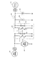
図1は本発明の第1実施例としての動力出力装置を搭載するハイブリッド自動車20の構成の概略を示す構成図であり、図2は第1実施例のハイブリッド自動車20に搭載した動力出力装置の電気的な接続関係を例示する接続関係図である。第1実施例のハイブリッド自動車20は、図1および図2に示すように、ガソリンにより駆動するエンジン22と、エンジンエンジン22からの動力を変速してデファレンシャルギヤ51を介して前輪52a,52bに出力するオートマチックトランスミッション24と、エンジン22の動力を用いて駆動用の直流電力を発電する直流発電機30と、この直流発電機30からの発電電力の供給を受けてデファレンシャルギヤ53を介して後輪54a,54bに動力を出力する直流電動機32と、直流発電機30から直流電動機32への駆動系の電力ラインに接続された昇降圧チョッパ34と、この昇降圧チョッパ34によって充放電されるキャパシタ36と、エンジン22からの動力を用いて補機44a,44b等に供給する電力を発電するオルタネータ40と、オルタネータ40から補機44a,44bへの補機系の電力ラインに接続されて充放電する定格電圧が12Vのバッテリ42と、キャパシタ36とバッテリ42との接続および接続の解除を行なうリレー46と、車両全体をコントロールする電子制御ユニット60と、を備える。
FIG. 1 is a configuration diagram showing an outline of the configuration of a
直流発電機30は、周知の三相交流発電機に全波整流器が取り付けられて構成されており、その回転子の回転軸は図示しないプーリやベルトによりエンジン22のクランクシャフトに接続されており、エンジン22のクランクシャフトの回転に伴って回転する。第1実施例では、直流発電機30としては最大発電電圧が60Vのものを用いた。
The
直流電動機32は、印加される電圧に応じたトルクを出力する発電機としても駆動可能な周知の直流発電電動機として構成されており、その出力軸(回転軸)はデファレンシャルギヤ53を介して後輪54a,54bに接続されている。第1実施例では、直流電動機32としては最大作動電圧60Vのものを用いた。
The
昇降圧チョッパ34は、図2に示すように、直列に接続された二個のトランジスタTr1,Tr2およびTr3,Tr4とこのトランジスタTr1,Tr2およびTr3,Tr4に対して対をなすように逆順方向に直列に接続された2個のダイオードD1,D2およびD3,D4の中間点を結ぶリアクトルLとにより構成されており、直流発電機30側の電力を昇圧または降圧してキャパシタ36側に供給したり、逆にキャパシタ36側の電力を昇圧または降圧して直流発電機30側に供給することができるようになっている。
As shown in FIG. 2, the step-up / step-down
この他、第1実施例では、キャパシタ36としては作動電圧が0V〜50V程度のものを用い、オルタネータ40としては発電電圧が13.5Vのものを用い、バッテリ42としては定格電圧が12Vの鉛蓄電池を用いた。なお、補機44a,44bとしてはエンジン22のスタータモータや前照灯など車両に搭載された種々の機器を挙げることができる。
In addition, in the first embodiment, a capacitor having an operating voltage of about 0V to 50V is used as the
電子制御ユニット60は、CPU62を中心とするマイクロコンピュータとして構成されており、CPU62の他に、処理プログラムなどを記憶するROM64やデータを一時的に記憶するRAM66,図示しない入出力ポートなどを備える。電子制御ユニット60には、直流発電機30から直流電動機32への駆動系の電力ラインに取り付けられた電圧センサ33からの駆動系電圧Vdやキャパシタ36の入出力端子に取り付けられた電圧センサ37からのキャパシタ36の作動電圧Vc,補機系の電力ラインに取り付けられた電圧センサ49からの補機系電圧Vhなどが入力ポートを介して入力されている。また、電子制御ユニット60からは、直流発電機30への駆動信号や昇降圧チョッパ34へのスイッチング制御信号,オルタネータ40への駆動信号,リレー46のアクチュエータ47への駆動信号などが出力ポートを介して出力されている。
The
こうして構成された第1実施例のハイブリッド自動車20は、図1に示すように、エンジン22からの動力がオートマッチックトランスミッション24およびデファレンシャルギヤ51を介して前輪52a,52bに出力可能に構成されていると共に直流電動機32からの動力がデファレンシャルギヤ53を介して後輪54a,54bに出力可能に構成されているから、エンジン22からの動力だけにより走行する前輪駆動走行(エンジン走行)と、エンジン22からの動力と直流電動機32からの動力とにより走行する4輪駆動走行と、直流電動機32からの動力だけにより走行する後輪駆動走行(モータ走行)とが可能である。第1実施例のハイブリッド自動車20の走行状態と各機器の状態との一覧を次表1に示す。なお、表中、丸印は運転または駆動している状態を示し、バツ印は運転停止または駆動停止している状態を示し、三角印は運転または駆動している状態と運転停止または駆動停止している状態のいずれでも構わない状態を示し、黒丸印は回生制御により駆動している状態を示す。また、チョッパ(昇降圧チョッパ34を意味する)の欄の矢印は、その方向への電力の供給が行なわれるよう電圧を昇降圧している状態を示す。キャパシタまたはバッテリの欄の「放電」や「充電」はキャパシタ36やバッテリ42の放電状態や充電状態を示し、「−」印は放電状態であっても充電状態であってもよい状態を示す。以下、この表を参照しながら第1実施例のハイブリッド自動車20の走行状態について説明する。
As shown in FIG. 1, the

前輪駆動走行(エンジン走行)は、表1の前輪駆動に示すように、直流発電機30による発電を停止すると共に昇降圧チョッパ34の作動を停止することにより直流電動機32への電力供給をしない状態でエンジン22を運転することにより行なうことができる。オルタネータ40は、エンジン22が運転されるから、これに伴って駆動する。リレー46はオフされているから、バッテリ42は、オルタネータ40の発電電力と補機44a,44bの消費電力とに伴って放電状態となったり充電状態となったりする。なお、こうした前輪駆動走行の状態で直流発電機30を駆動すると共に直流発電機30からの電力を昇降圧チョッパ34によって昇降圧してキャパシタ36を充電したり(表1の前輪駆動の2段目参照)、更に、リレー46をオンとしてバッテリ42を充電することもできる(表1の前輪駆動の3段目参照)。
In front wheel drive running (engine running), as shown in Table 1 front wheel drive, the power generation by the
4輪駆動走行は、表1の4輪駆動に示すように、エンジン22を運転して前輪52a,52bに動力を出力し、直流発電機30を駆動してエンジン22からの動力の一部を用いて発電すると共にこの発電電力を用いて直流電動機32を駆動することにより行なうことができる。このとき、キャパシタ36からの電力を昇降圧チョッパ34によって昇降圧して直流電動機32に供給することもできる(表1の4輪駆動の2段目参照)。この場合、直流電動機32には直流発電機30からの電力とキャパシタ36からの電力が供給されることになる。逆に、直流発電機30からの電力を昇降圧チョッパ34によって昇降圧してキャパシタ36を充電することもできる(表1の4輪駆動の3段目参照)。さらに、リレー46をオン(接続)として補機系の電力ラインを昇降圧チョッパ34を介して駆動系の電力ラインに接続すれば、バッテリ42からの電力を昇降圧チョッパ34により昇降圧して直流電動機32に供給することもできる(表1の4輪駆動の4段目)。このとき、リレー46をオンするタイミングとしては、電圧センサ37により検出されるキャパシタ36の作動電圧Vcが電圧センサ49により検出される補機系電圧Vhに一致するタイミングとするのが好ましい。これにより、キャパシタ36に蓄えられた電力だけでなく、補機系のバッテリ42に蓄えられた電力をも直流電動機32に供給することができる。この場合、キャパシタ36は、リレー46によりバッテリ42に接続されるから、バッテリ42の端子間電圧に保持される。なお、直流発電機30からの電力を昇降圧チョッパ34によって昇降圧してバッテリ42を充電することもできる(表1の4輪駆動の5段目参照)。
In the four-wheel drive running, as shown in the four-wheel drive in Table 1, the
後輪駆動走行(モータ走行)は、表1の後輪駆動の上段に示すように、エンジン22の運転を停止した状態でキャパシタ36からの電力を昇降圧チョッパ34によって昇降圧して直流電動機32に供給することにより行なうことができる。この場合、リレー46をオン(接続)として補機系の電力ラインを昇降圧チョッパ34を介して駆動系の電力ラインに接続すれば、バッテリ42からの電力を昇降圧チョッパ34により昇降圧して直流電動機32に供給することもできる(表1の後輪駆動の下段参照)。リレー46をオンするタイミングとしては、電圧センサ37により検出されるキャパシタ36の作動電圧Vcが電圧センサ49により検出される補機系電圧Vhに一致するタイミングとするのが好ましい。これにより、キャパシタ36に蓄えられた電力だけでなく、補機系のバッテリ42に蓄えられた電力を用いてモータ走行を行なうことができる。この場合も、キャパシタ36は、リレー46によりバッテリ42に接続されるから、バッテリ42の端子間電圧に保持される。後輪駆動走行では、エンジン22はアイドリング運転状態などで運転されていてもよいし、その運転を停止していてもよい。オルタネータ40は、こうしたエンジン22の運転によりその駆動が決まる。
In the rear wheel drive running (motor running), as shown in the upper stage of the rear wheel drive in Table 1, the electric power from the
また、第1実施例のハイブリッド自動車20は、制動時には、表1の制動時の上段に示すように、車両の運動エネルギを電力として回収してキャパシタ36に蓄えることができる。このときには、直流電動機32を発電機として駆動し、直流電動機32からの発電電力を昇降圧チョッパ34により昇降圧してキャパシタ36に供給すればよい。昇降圧チョッパ34の制御は、昇降圧チョッパ34からキャパシタ36へ供給しようとする電圧が電圧センサ37により検出されるキャパシタ36の作動電圧Vcより若干高い電圧となるよう行なえばよい。更に、リレー46をオン(接続)として補機系の電力ラインを昇降圧チョッパ34を介して駆動系の電力ラインに接続すれば、直流電動機32からの発電電力を昇降圧チョッパ34により昇降圧してバッテリ42を充電することもできる(表1の制動時の下段参照)。このとき、リレー46をオンするタイミングとしては電圧センサ37により検出されるキャパシタ36の作動電圧Vcが電圧センサ49により検出される補機系電圧Vhに一致するタイミングとするのが好ましく、リレー46をオフするタイミングとしてはオルタネータ40の調整電圧に一致するタイミングとするのが好ましい。この場合も、キャパシタ36はバッテリ42の端子間電圧に保持される。制動時には、エンジン22はアイドリング運転状態などで運転されていてもよいし、その運転を停止していてもよい。オルタネータ40は、こうしたエンジン22の運転によりその駆動が決まる。
Further, the
以上説明した第1実施例のハイブリッド自動車20によれば、キャパシタ36に蓄えられた電力やバッテリ42からの電力を昇降圧チョッパ34により昇降圧して直流電動機32に供給することができるから、直流電動機32に直流発電機30による発電電力より大きな電力を供給することができる。また、キャパシタ36からの電力やバッテリ42からの電力を昇降圧チョッパ34により昇降圧して直流電動機32に供給することができるから、エンジン22を停止した状態でも直流電動機32に十分な電力を供給することができる。この結果、直流電動機32からの動力だけにより走行することができる。更に、制動時には、直流電動機32を発電機として駆動し、車両の運動エネルギを電力としてキャパシタ36やバッテリ42に蓄えることができるから、車両全体としてのエネルギ効率を向上させることができる。また、直流発電機30による発電や直流電動機32への電力供給によって駆動系の電力ラインの電圧が変化しても、昇降圧チョッパ34により昇降圧された電圧によりキャパシタ36の充放電を行なうと共にキャパシタ36の作動電圧Vcが補機系の電力ラインに適合する電圧のときにのみリレー46をオン(接続)とするから、キャパシタ36が破損したりバッテリ42や補機44a,44bに高電圧が作用することにより破損するのを抑止することできる。
According to the
第1実施例のハイブリッド自動車20では、昇降圧チョッパ34を介してキャパシタ36を駆動系の電力ラインに接続するものとしたが、図3の変形例に示すように、昇降圧チョッパ34を介して充放電可能なバッテリ42より定格電圧が高い二次電池36bを駆動系の電力ラインに接続するものとしてもよい。この場合、リレー46に代えてDC/DCコンバータ46bを用いるのが好ましい。こうすれば、DC/DCコンバータ46bを制御することより、補機系のバッテリ42をより多くの頻度に亘って用いることができる。この変形例のハイブリッド自動車20の走行状態と各機器の状態との一覧を次表2に示す。基本的には、上述した表1と同様である。なお、表2中、DC/DC(DC/DCコンバータ46bを意味する)の矢印はその方向への電力の供給が行なわれるよう電圧調整をしている状態を示し、「−」印は任意の状態を示す。
In the
第1実施例のハイブリッド自動車20では、昇降圧チョッパ34とリレー46とを介して補機系の電力ラインを駆動系の電力ラインに接続するものとしたが、補機系の電力ラインについては駆動系の電力ラインに接続しないものとしてもよい。
In the
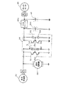
次に、本発明の第2実施例としてのハイブリッド自動車20Bについて説明する。図4は、第2実施例のハイブリッド自動車20Bに搭載した動力出力装置の電気的な接続関係を例示する接続関係図である。第2実施例のハイブリッド自動車20Bは、図示するように、昇降圧チョッパ34のリアクトルLの中間点に補機系の電力ラインが接続されている点やキャパシタ36に代えて二次電池36bを備える点,リレー46を備えない点を除いて図1および図2に例示した第1実施例のハイブリッド自動車20と同一の構成をしている。第2実施例のハイブリッド自動車20Bの構成のうち第1実施例のハイブリッド自動車20の構成と同一の構成については同一の符号を付し、その説明は省略する。
Next, a hybrid vehicle 20B as a second embodiment of the present invention will be described. FIG. 4 is a connection relationship diagram illustrating the electrical connection relationship of the power output apparatus mounted on the hybrid vehicle 20B of the second embodiment. The hybrid vehicle 20B of the second embodiment includes a
第2実施例のハイブリッド自動車20Bでは、昇降圧チョッパ34のリアクトルLの中間点の電圧がバッテリ42を充放電可能な範囲の電圧となるように昇降圧チョッパ34のトランジスタTr1〜Tr4のスイッチング制御が行なわれる。即ち、直流発電機30の発電電力や直流電動機32の発電電力あるいは二次電池36bからの電力によりバッテリ42を充電するときにはリアクトルLの中間点の電圧がバッテリ42の適正な充電電圧となるよう昇降圧チョッパ34のトランジスタTr1〜Tr4のスイッチング制御が行なわれ、バッテリ42からの電力により直流電動機32を駆動したり二次電池36bを充電するときにはリアクトルLの中間点の電圧がバッテリ42の適正な放電電圧となるよう昇降圧チョッパ34のトランジスタTr1〜Tr4のスイッチング制御が行なわれるのである。
In the hybrid vehicle 20B of the second embodiment, switching control of the transistors Tr1 to Tr4 of the step-up / step-down
こうした第2実施例のハイブリッド自動車20Bでも第1実施例のハイブリッド自動車20と同様に、エンジン22からの動力だけにより走行する前輪駆動走行(エンジン走行)やエンジン22からの動力と直流電動機32からの動力とにより走行する4輪駆動走行,直流電動機32からの動力だけにより走行する後輪駆動走行(モータ走行)が可能である。第2実施例のハイブリッド自動車20Bの走行状態と各機器の状態との一覧を次表3に示す。
In the hybrid vehicle 20B of the second embodiment, as in the
第2実施例のハイブリッド自動車20Bでも、前輪駆動走行(エンジン走行)は、直流発電機30と直流電動機32の接続関係が第1実施例のハイブリッド自動車20と同一であることから、表3の前輪駆動に示すように、基本的には第1実施例のハイブリッド自動車20と同様に行なわれる。直流発電機30を駆動すると共に直流発電機30からの電力を昇降圧チョッパ34によって昇降圧して二次電池36bを充電する際やバッテリ42を充電する際にはバッテリ42の充放電の状態に基づいて昇降圧チョッパ34のリアクトルLの中間点が適正な電圧になるよう昇降圧チョッパ34のトランジスタTr1〜Tr4のスイッチング制御が行なわれる。
Also in the hybrid vehicle 20B of the second embodiment, the front wheel drive travel (engine travel) is the same as the
4輪駆動走行は、表3の4輪駆動に示すように、第1実施例のハイブリッド自動車20と同様に、エンジン22を運転して前輪52a,52bに動力を出力し、直流発電機30を駆動してエンジン22からの動力の一部を用いて発電すると共にこの発電電力を用いて直流電動機32を駆動することにより行なうことができる。この他、直流発電機30からの発電電力に加えて二次電池36bからの電力やバッテリ42からの電力を昇降圧チョッパ34によって昇降圧して直流電動機32に供給することにより行なうこともできる(表3の4輪駆動の2段目および4段目参照)。このとき、昇降圧チョッパ34のリアクトルLの中間点の電圧を調整することにより、バッテリ42や二次電池36bの一方または双方からの電力を直流電動機32に供給することができる。また、直流発電機30からの電力を直流電動機32に供給しながら直流発電機30からの電力を昇降圧チョッパ34によって昇降圧して二次電池36bやバッテリ42を充電することもできる(表3の4輪駆動の3段目および5段目参照)。このときも昇降圧チョッパ34のリアクトルLの中間点の電圧を調整することにより、直流発電機30からの発電電力を直流電動機32に供給しながらバッテリ42や二次電池36bの一方または双方を充電することができる。
In the four-wheel drive running, as shown in the four-wheel drive in Table 3, the
後輪駆動走行(モータ走行)は、表3の後輪駆動の1段目および2段目に示すように、エンジン22の運転を停止した状態で二次電池36bからの電力やバッテリ42からの電力を昇降圧チョッパ34によって昇降圧して直流電動機32に供給することにより行なうことができる。このとき、昇降圧チョッパ34のリアクトルLの中間点の電圧を調整することにより、二次電池36bからの電力とバッテリ42からの電力を合わせて直流電動機32に供給することもできるし(表3の後輪駆動の3段目参照)、二次電池36bからの電力を直流電動機32に供給すると共に二次電池36bの電力の一部を用いてバッテリ42を充電することもできる(表3の後輪駆動の4段目参照)。
As shown in the first and second stages of rear wheel drive in Table 3, the rear wheel drive travel (motor travel) is performed with the electric power from the
また、第2実施例のハイブリッド自動車20Bでは、制動時には、表3の制動時に示すように、直流電動機32を発電機として駆動し、直流電動機32からの発電電力を昇降圧チョッパ34により昇降圧して二次電池36bやバッテリ42の一方または双方を充電することができる。このとき、昇降圧チョッパ34のリアクトルLを調整することによりバッテリ42については充電されないようにすることもできる。
Further, in the hybrid vehicle 20B of the second embodiment, during braking, as shown in braking in Table 3, the
以上説明した第2実施例のハイブリッド自動車20Bによれば、二次電池36bからの電力やバッテリ42からの電力を昇降圧チョッパ34により昇降圧して直流電動機32に供給することができるから、直流電動機32に直流発電機30による発電電力より大きな電力を供給することができる。また、二次電池36bからの電力やバッテリ42からの電力を昇降圧チョッパ34により昇降圧して直流電動機32に供給することができるから、エンジン22を停止した状態でも直流電動機32に十分な電力を供給することができる。この結果、直流電動機32からの動力だけにより走行することができる。更に、制動時には、直流電動機32を発電機として駆動し、車両の運動エネルギを電力として二次電池36bやバッテリ42に蓄えることができるから、車両全体としてのエネルギ効率を向上させることができる。また、昇降圧チョッパ34のリアクトルLの中間点に補機系の電力ラインを接続すると共にリアクトルLの中間点の電圧を調整することにより、バッテリ42の充放電を自由に行なうことができると共に第1実施例のハイブリッド自動車20が備えるリレー46やその変形例が備えるDC/DCコンバータ46bなどの電圧の不均衡を補償する回路などを設ける必要がない。
According to the hybrid vehicle 20B of the second embodiment described above, the electric power from the
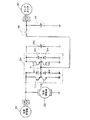
第2実施例のハイブリッド自動車20Bでは、補機系の電力ラインを昇降圧チョッパ34のリアクトルLの中間点に直接接続したが、図5の変形例に示すように、補機系の電力ラインをリレー46を介して昇降圧チョッパ34のリアクトルLの中間点に接続するものとしてもよい。この場合、表3に例示した状態に加えてリレー46のオンオフの状態を考えることができる。この変形例のハイブリッド自動車では、第2実施例のハイブリッド自動車20Bと異なり、昇降圧チョッパ34のリアクトルLの中間点の電圧を常にバッテリ42の充放電可能な範囲の電圧になるように昇降圧チョッパ34のトランジスタTr1〜Tr4をスイッチング制御する必要はない。即ち、昇降圧チョッパ34のリアクトルLの中間点の電圧がバッテリ42の充放電可能な電圧範囲外となるときやその可能性があるときにはリレー46により接続を解除すればよい。例えば、駆動系の電力ラインの電圧がバッテリ42の電圧より低いときや直流電動機32を発電機として駆動するときなどにはリレー46をオフ(接続の解除)とすればよい。こうすることにより、補機系の電力ラインに接続された補機44a,44bなどを保護することができる。このように、リレー46を設けることにより、電力制御の自由度が高くなると共に機器の保護を容易に且つ効果的に行なうことができる。
In the hybrid vehicle 20B of the second embodiment, the auxiliary power line is directly connected to the intermediate point of the reactor L of the step-up / down
上述した第1実施例や第2実施例あるいはその変形例では、エンジン22や直流発電機30,直流電動機32,昇降圧チョッパ34,キャパシタ36などにより構成される動力出力装置を自動車に搭載するものとしたが、自動車以外の車両や船舶,航空機などの移動体に搭載するものとしてもよく、あるいは建設機械などの移動しない機器に適用するものとしてもよい。
In the first embodiment, the second embodiment, or a modification thereof described above, a power output device including the
以上、本発明を実施するための最良の形態について実施例を用いて説明したが、本発明はこうした実施例に何等限定されるものではなく、本発明の要旨を逸脱しない範囲内において、種々なる形態で実施し得ることは勿論である。 The best mode for carrying out the present invention has been described with reference to the embodiments. However, the present invention is not limited to these embodiments, and various modifications can be made without departing from the gist of the present invention. Of course, it can be implemented in the form.
本発明は、自動車産業に利用可能である。 The present invention is applicable to the automobile industry.
20,20B ハイブリッド自動車、22 エンジン、24 オートマチックトランスミッション、30 直流発電機、32 直流電動機、33 電圧センサ、34 昇降圧チョッパ、36 キャパシタ、36b 二次電池、37 電圧センサ、40 オルタネータ、42 バッテリ、44a,44b 補機、46 リレー、46b DC/DCコンバータ、47 アクチュエータ、49 電圧センサ、51 デファレンシャルギヤ、52a,52b 前輪、53 デファレンシャルギヤ、54a,54b 後輪、60 電子制御ユニット、62 CPU、64 ROM、66 RAM。
20, 20B Hybrid car, 22 engine, 24 automatic transmission, 30 DC generator, 32 DC motor, 33 voltage sensor, 34 buck-boost chopper, 36 capacitor, 36b secondary battery, 37 voltage sensor, 40 alternator, 42 battery, 44a , 44b Auxiliary machine, 46 Relay, 46b DC / DC converter, 47 Actuator, 49 Voltage sensor, 51 Differential gear, 52a, 52b Front wheel, 53 Differential gear, 54a, 54b Rear wheel, 60 Electronic control unit, 62 CPU, 64
Claims (15)
駆動用の動力を出力可能な内燃機関と、
該内燃機関からの動力を用いて発電する直流発電機と、
該直流発電機からの電力を用いて駆動用の動力を出力可能な直流電動機と、
充放電可能な蓄電手段と、
前記直流発電機からの電力を用いて前記蓄電手段を充電するための電圧調整と該蓄電手段からの電力を前記直流電動機へ供給するための電圧調整とが可能な電圧調整手段と、
を備える動力出力装置。 A power output device that outputs driving power,
An internal combustion engine capable of outputting driving power;
A DC generator that generates power using power from the internal combustion engine;
A DC motor capable of outputting driving power using electric power from the DC generator;
Charge / discharge power storage means;
Voltage adjusting means capable of voltage adjustment for charging the power storage means using power from the DC generator and voltage adjustment for supplying power from the power storage means to the DC motor;
A power output device comprising:
前記直流電動機は発電可能な電動機であり、
前記電圧調整手段は、前記直流電動機からの発電電力を用いて前記蓄電手段を充電するための電圧調整が可能な手段である
動力出力装置。 The power output device according to claim 1,
The DC motor is a motor capable of generating power,
The voltage adjusting means is a means capable of adjusting a voltage for charging the power storage means by using generated power from the DC motor.
前記蓄電手段は、第1の電圧範囲で作動する第1蓄電手段であり、
前記第1の電圧範囲とは異なる第2の電圧範囲で作動する第2蓄電手段と、
前記第1蓄電手段と前記第2蓄電手段との間に配置され、該第1蓄電手段側の電圧と該第2蓄電手段側の電圧との不均衡を補償する電圧不均衡補償手段と、
を備える動力出力装置。 The power output device according to any one of claims 1 to 3,
The power storage means is a first power storage means operating in a first voltage range;
Second power storage means operating in a second voltage range different from the first voltage range;
A voltage imbalance compensation unit disposed between the first power storage unit and the second power storage unit to compensate for an imbalance between the voltage on the first power storage unit side and the voltage on the second power storage unit side;
A power output device comprising:
前記蓄電手段は、第1の電圧範囲で作動する第1蓄電手段であり、
前記昇降圧チョッパのリアクトル中間点に接続され前記第1の電圧範囲とは異なる第2の電圧範囲で作動する充放電可能な第2蓄電手段を備える
動力出力装置。 The power output device according to claim 3,
The power storage means is a first power storage means operating in a first voltage range;
A power output apparatus comprising: chargeable / dischargeable second power storage means connected to a reactor midpoint of the step-up / down chopper and operating in a second voltage range different from the first voltage range.
前記第1蓄電手段は、第1の電圧を定格とする二次電池であり、
前記第2蓄電手段は、第1の電圧より低い第2の電圧を定格とする二次電池である
動力出力装置。 The power output device according to any one of claims 6 to 10,
The first power storage means is a secondary battery rated at a first voltage;
The second power storage means is a secondary battery rated at a second voltage lower than the first voltage.
前記第1蓄電手段は、キャパシタであり、
前記第2蓄電手段は、所定の電圧を定格とする二次電池である
動力出力装置。 The power output device according to any one of claims 4 to 10,
The first power storage means is a capacitor;
The second power storage means is a secondary battery rated at a predetermined voltage.
前記内燃機関の動力を用いて前記第2の電圧範囲内の直流電力を発電して前記第2蓄電手段を充電可能な第2直流発電機と、
前記第2直流発電機からの電力供給と前記第2蓄電手段からの電力供給を受けて駆動する補機と、
を備える動力出力装置。 The power output device according to any one of claims 4 to 12,
A second DC generator capable of generating DC power within the second voltage range using the power of the internal combustion engine and charging the second power storage means;
An auxiliary machine driven by receiving power supply from the second DC generator and power supply from the second power storage means;
A power output device comprising:
15. The automobile according to claim 14, wherein an axle for outputting power from the internal combustion engine is different from an axle for outputting power from the DC motor.
Priority Applications (1)
| Application Number | Priority Date | Filing Date | Title |
|---|---|---|---|
| JP2003370514A JP2005137125A (en) | 2003-10-30 | 2003-10-30 | Power output device and automobile equipped with the same. |
Applications Claiming Priority (1)
| Application Number | Priority Date | Filing Date | Title |
|---|---|---|---|
| JP2003370514A JP2005137125A (en) | 2003-10-30 | 2003-10-30 | Power output device and automobile equipped with the same. |
Publications (1)
| Publication Number | Publication Date |
|---|---|
| JP2005137125A true JP2005137125A (en) | 2005-05-26 |
Family
ID=34647506
Family Applications (1)
| Application Number | Title | Priority Date | Filing Date |
|---|---|---|---|
| JP2003370514A Pending JP2005137125A (en) | 2003-10-30 | 2003-10-30 | Power output device and automobile equipped with the same. |
Country Status (1)
| Country | Link |
|---|---|
| JP (1) | JP2005137125A (en) |
Cited By (3)
| Publication number | Priority date | Publication date | Assignee | Title |
|---|---|---|---|---|
| US7088595B2 (en) * | 2004-03-31 | 2006-08-08 | Denso Corporation | Reversible buck-boost chopper circuit, and inverter circuit with the same |
| RU2348541C2 (en) * | 2007-08-08 | 2009-03-10 | Фархат Умарович Ашрапов | Braking energy recuperator |
| EP3264577A1 (en) * | 2016-06-29 | 2018-01-03 | WABCO GmbH | Voltage regulator unit, vehicle controller and method for pre-regulating a supply voltage |
-
2003
- 2003-10-30 JP JP2003370514A patent/JP2005137125A/en active Pending
Cited By (3)
| Publication number | Priority date | Publication date | Assignee | Title |
|---|---|---|---|---|
| US7088595B2 (en) * | 2004-03-31 | 2006-08-08 | Denso Corporation | Reversible buck-boost chopper circuit, and inverter circuit with the same |
| RU2348541C2 (en) * | 2007-08-08 | 2009-03-10 | Фархат Умарович Ашрапов | Braking energy recuperator |
| EP3264577A1 (en) * | 2016-06-29 | 2018-01-03 | WABCO GmbH | Voltage regulator unit, vehicle controller and method for pre-regulating a supply voltage |
Similar Documents
| Publication | Publication Date | Title |
|---|---|---|
| AU2002302166B2 (en) | Hybrid vehicle and control method therefor | |
| JP3410022B2 (en) | Control device for hybrid vehicle | |
| EP2292488B1 (en) | Control apparatus for hybrid vehicle | |
| CN101336173B (en) | Power supply apparatus for vehicle, and method of controlling power supply apparatus | |
| CN101020424B (en) | Control device and control method for electric vehicle | |
| EP1531078B1 (en) | Control system and control method for motor powered four wheel drive vehicle | |
| CN100358746C (en) | Control system and controlling method for motor drive four wheel drive vehicle | |
| US5714851A (en) | Serial hybrid drive arrangement for a motor vehicle | |
| US9266525B2 (en) | Vehicle, method for controlling vehicle, and control device of vehicle | |
| US20180105043A1 (en) | Power supply system | |
| JP2000245009A (en) | Hybrid vehicle | |
| US8091666B2 (en) | Electrically powered vehicle, control device for electrically powered vehicle, and computer readable medium | |
| JP2008306795A (en) | Discharge control device for power circuit | |
| CN107415684A (en) | Hybrid electric drive system | |
| CN108099700A (en) | The motor of vehicle with multiple motors is controlled | |
| JP2007098981A (en) | Vehicle power supply | |
| US7253573B2 (en) | Power source for a hybrid vehicle | |
| JP2006312352A (en) | Control device for drive system | |
| JP2000224709A (en) | Power supply | |
| JP2000245008A (en) | Hybrid vehicle | |
| JP2005532777A (en) | Power transmission method and apparatus for a motor vehicle including a heat engine and at least one electric machine | |
| CN1618645A (en) | Control device and control method of motor-driven 4wd vehicle | |
| JP2009060725A (en) | Vehicle and vehicle control method | |
| JP2005137125A (en) | Power output device and automobile equipped with the same. | |
| JP4010085B2 (en) | Electric and hybrid vehicles |
Legal Events
| Date | Code | Title | Description |
|---|---|---|---|
| A621 | Written request for application examination |
Free format text: JAPANESE INTERMEDIATE CODE: A621 Effective date: 20060522 |
|
| A131 | Notification of reasons for refusal |
Free format text: JAPANESE INTERMEDIATE CODE: A131 Effective date: 20070220 |
|
| A521 | Request for written amendment filed |
Free format text: JAPANESE INTERMEDIATE CODE: A523 Effective date: 20070420 |
|
| A131 | Notification of reasons for refusal |
Free format text: JAPANESE INTERMEDIATE CODE: A131 Effective date: 20071204 |
|
| A521 | Request for written amendment filed |
Free format text: JAPANESE INTERMEDIATE CODE: A523 Effective date: 20080116 |
|
| A02 | Decision of refusal |
Free format text: JAPANESE INTERMEDIATE CODE: A02 Effective date: 20080708 |