JP2005123747A - Audio reproducing apparatus - Google Patents
Audio reproducing apparatus Download PDFInfo
- Publication number
- JP2005123747A JP2005123747A JP2003354235A JP2003354235A JP2005123747A JP 2005123747 A JP2005123747 A JP 2005123747A JP 2003354235 A JP2003354235 A JP 2003354235A JP 2003354235 A JP2003354235 A JP 2003354235A JP 2005123747 A JP2005123747 A JP 2005123747A
- Authority
- JP
- Japan
- Prior art keywords
- audio
- output
- speaker
- maximum output
- power supply
- Prior art date
- Legal status (The legal status is an assumption and is not a legal conclusion. Google has not performed a legal analysis and makes no representation as to the accuracy of the status listed.)
- Pending
Links
Images
Landscapes
- Stereophonic System (AREA)
- Circuit For Audible Band Transducer (AREA)
- Amplifiers (AREA)
Abstract
Description
本発明は、5.1CH等の複数の出力チャンネルを有するオーディオ再生装置に関する。 The present invention relates to an audio reproducing apparatus having a plurality of output channels such as 5.1CH.
近年デジタルオーディオ技術やスピーカ等の音響技術の進展に伴い、マルチチャンネルによるオーディオ再生装置が開発されてきており、原音に忠実で臨場感に優れた音響効果を有することから、広く普及してきている。 In recent years, with the progress of digital audio technology and acoustic technology such as speakers, multi-channel audio playback devices have been developed and have become widely used because they have an acoustic effect that is faithful to the original sound and excellent in realism.
こうしたオーディオ再生装置では、デジタル信号処理回路から各チャンネル毎に音声信号が出力されて、各チャンネルに対応したD/A変換器及び音声増幅器に伝送されてそれぞれのスピーカから音声が再生出力される。マルチチャンネル化に伴い、それぞれの出力チャンネルの役割が多様化してきている。例えば、5.1CHのマルチチャンネル・オーディオ再生装置の場合、中央及び左右のフロントスピーカ、左右のリアスピーカ並びに低音用のウーハーが設けられており、それぞれの出力チャンネルの役割に対応して音声信号の処理やスピーカの特性の設定等が行われてきている。 In such an audio reproducing apparatus, an audio signal is output for each channel from the digital signal processing circuit, transmitted to a D / A converter and an audio amplifier corresponding to each channel, and audio is reproduced and output from each speaker. The role of each output channel has been diversified along with the multi-channel. For example, in the case of a 5.1CH multi-channel audio playback device, a center and left and right front speakers, left and right rear speakers, and a low-frequency woofer are provided, and an audio signal corresponding to the role of each output channel is provided. Processing, setting of speaker characteristics, and the like have been performed.
例えば、特許文献1では、2つのスピーカにそれぞれ接続された音声増幅器に供給される電源電圧を可変とすることで、各音声増幅器の駆動電力を可変とし、2つのスピーカのパワー配分を容易に変更できるようにした点が記載されている。また、特許文献2では、スピーカの入力インピーダンスを演算し、この演算結果に基づいてスピーカに接続された増幅回路に供給される電源トランスのタップを切り替えて、スピーカのインピーダンスに応じた最大音量を自動的に得ることができる点が記載されている。また、特許文献3では、リレー回路の接点を切り換えて、2チャンネル系のスピーカと、マルチチャンネルのうちの2チャンネル系とは別のいずれかのチャンネルのパワーアンプとを接続するように、パワーアンプとスピーカとの間にリレー回路を設け、2チャンネル・オーディオ信号を再生する際にも、音量が大きく再生出力される点が記載されている。
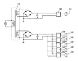
従来のオーディオ再生装置では、各チャンネルの最大出力が異なる場合、例えば、5.1CHでは、低音用のウーハーの出力を他のスピーカの出力に比べ2倍以上に大きくして音量を大きくしているが、この場合には、図4に示すように、それぞれの出力に対応して電源電圧を供給している。電源トランス100からは、整流されて2つの電源電圧V1及びV2が供給されており、電源電圧V1は、ウーハー201に接続された増幅器200に供給され、電源電圧V2は、ウーハー201以外のスピーカ305〜309にそれぞれ接続された増幅器300〜304に供給されている。電源電圧V1及びV2は、異なる電圧値に設定されるため2つの電源回路が必要となる。さらに、それぞれ絶縁した状態に回路配置等を設計する必要があり、回路基板を別々に設けたり、絶縁シートで絶縁状態にするといったコスト負担増の要因となる。
In the conventional audio reproduction apparatus, when the maximum output of each channel is different, for example, in 5.1CH, the output of the bass woofer is increased more than twice the output of other speakers to increase the volume. However, in this case, as shown in FIG. 4, the power supply voltage is supplied corresponding to each output. The
上述した先行文献では、出力チャンネルの音声増幅器に供給される電源電圧を変更して、パワー配分を変化させたり、スピーカのインピーダンスに対応させたりしているが、いずれも複雑な回路構成となっており、やはりコスト負担増が避けられない。 In the above-mentioned prior art documents, the power supply voltage supplied to the audio amplifier of the output channel is changed to change the power distribution or to correspond to the impedance of the speaker, but all have complicated circuit configurations. However, an increase in cost is inevitable.
そこで、本発明は、簡単な回路構成で各チャンネルの最大出力が異なる場合に対応することができ、従来どおりの音響効果を発揮することが可能なオーディオ再生装置を提供することを目的とするものである。 SUMMARY OF THE INVENTION Accordingly, an object of the present invention is to provide an audio reproducing apparatus that can cope with a case where the maximum output of each channel is different with a simple circuit configuration and can exhibit a conventional acoustic effect. It is.
本発明に係るオーディオ再生装置は、複数の出力チャンネル毎に音声増幅器及びスピーカを備えるとともに少なくとも1つの出力チャンネルの最大出力が異なるように設定されているオーディオ再生装置において、前記各音声増幅器に同一の電源電圧を供給する単一の電源回路を備え、各出力チャンネルの最大出力に対応してスピーカのインピーダンスが設定されていることを特徴とする。 The audio reproduction device according to the present invention is an audio reproduction device that includes an audio amplifier and a speaker for each of a plurality of output channels, and is set so that the maximum output of at least one output channel is different. A single power supply circuit for supplying a power supply voltage is provided, and the impedance of the speaker is set corresponding to the maximum output of each output channel.
また、本発明に係る別のオーディオ再生装置は、複数の出力チャンネル毎に音声増幅器及びスピーカを備えるとともに少なくとも1つの出力チャンネルの最大出力が異なるように設定されているオーディオ再生装置において、前記各音声増幅器に同一の電源電圧を供給する単一の電源回路を備え、出力チャンネルの最大出力に対応して複数の音声増幅器を1つのスピーカに接続していることを特徴とする。 Another audio reproduction apparatus according to the present invention is an audio reproduction apparatus that includes an audio amplifier and a speaker for each of a plurality of output channels and is set so that a maximum output of at least one output channel is different. A single power supply circuit for supplying the same power supply voltage to the amplifier is provided, and a plurality of audio amplifiers are connected to one speaker corresponding to the maximum output of the output channel.
さらに、上記のオーディオ再生装置において、前記音声増幅器は、すべて共通の放熱板に取り付けられていることを特徴とする。 Furthermore, in the above audio reproducing apparatus, all of the audio amplifiers are attached to a common heat sink.
上記のような構成を有することで、各出力チャンネルの音声増幅器に同一の電圧を供給するようにして電源回路を単一化でき、電源に関する回路系全体が単純化される。すなわち、従来複数設ける必要があった電源回路を1つにすることで部品の削減が図られ、さらに電源トランスも小さくできるため、太い巻線のものを採用することで、レギュレーションが向上して音質や過渡応答性が改善される。 By having the configuration as described above, the power supply circuit can be unified by supplying the same voltage to the audio amplifier of each output channel, and the entire circuit system related to the power supply is simplified. In other words, by reducing the number of parts by using a single power supply circuit that has conventionally been required to be provided, and by reducing the size of the power transformer, the use of thick windings improves regulation and improves sound quality. And transient response is improved.
そして、同一の電圧を各音声増幅器に供給するので、1つの基板上にすべての音声増幅器を取り付けることができ、基板自体もコンパクト化でき、基板に取り付ける放熱構造も1つで済む。したがって、回路系全体の構造が単純化できるため、コストダウンが図られ、生産効率も向上するようになる。 Since the same voltage is supplied to each audio amplifier, all the audio amplifiers can be mounted on one board, the board itself can be made compact, and only one heat dissipation structure can be attached to the board. Therefore, since the structure of the entire circuit system can be simplified, the cost can be reduced and the production efficiency can be improved.
また、スピーカのインピーダンスを最大出力に対応して設定しているので、例えば、5.1CHのようにウーハー用のスピーカの最大出力を大きく設定したい場合には、他のスピーカよりも小さいインピーダンスのスピーカを用いれば、その分最大出力が大きくなり、スピーカの音質も従来通り維持される。 In addition, since the impedance of the speaker is set corresponding to the maximum output, for example, when it is desired to set the maximum output of the woofer speaker to a large value such as 5.1CH, the speaker having a smaller impedance than the other speakers. Is used, the maximum output is increased accordingly, and the sound quality of the speaker is maintained as before.
出力チャンネルの最大出力を大きく設定したい場合には、複数の音声増幅器を1つのスピーカに接続して対応することもできる。すなわち、同一電圧が供給される複数の音声増幅器を設けておき、例えば、ある出力チャンネルのスピーカに2つの音声増幅器を接続すれば、他の出力チャンネルに比べて2倍の最大出力に設定することができる。 When it is desired to set a large maximum output channel, a plurality of audio amplifiers can be connected to one speaker. That is, if a plurality of audio amplifiers to which the same voltage is supplied are provided, and two audio amplifiers are connected to a speaker of a certain output channel, for example, the maximum output is set to twice that of other output channels. Can do.
なお、電源回路としては、例えば、トランス電源回路、スイッチング電源回路といったものが挙げられるが、本発明は、特定の電源回路に限定されるものではない。 Examples of the power supply circuit include a transformer power supply circuit and a switching power supply circuit, but the present invention is not limited to a specific power supply circuit.
以下、本発明に係る実施形態について詳しく説明する。なお、以下に説明する実施形態は、本発明を実施するにあたって好ましい具体例であるから、技術的に種々の限定がなされているが、本発明は、以下の説明において特に本発明を限定する旨明記されていない限り、これらの形態に限定されるものではない。 Hereinafter, embodiments according to the present invention will be described in detail. The embodiments described below are preferable specific examples for carrying out the present invention, and thus various technical limitations are made. However, the present invention is particularly limited in the following description. Unless otherwise specified, the present invention is not limited to these forms.
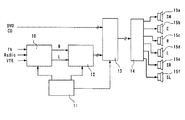
図1は、本発明に係る実施形態に関する全体ブロック図を示している。音声信号は、TV、ラジオ、VTR等から送信される2チャンネルの信号及びDVD、CD等から送信されるマルチチャンネルの信号がある。2チャンネル信号は、信号切換回路10において制御回路11の切換制御により1種類の信号が選択されてサラウンド処理回路12に入力される。サラウンド処理回路12によりマルチチャンネルに対応した信号処理が行われて、スイッチ回路13に入力される。スイッチ回路13は、制御回路11からの切換制御信号によりサラウンド処理回路12からの音声信号又はDVD等から入力された音声信号を選択して音声増幅器14に出力する。音声増幅器14から各スピーカ15a〜15fに駆動信号が出力されて、音声が出力される。
FIG. 1 shows an overall block diagram relating to an embodiment of the present invention. Audio signals include two-channel signals transmitted from TV, radio, VTR, etc., and multi-channel signals transmitted from DVD, CD, and the like. The two-channel signal is input to the
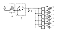
図2は、音声増幅器14に電源を供給する回路に関する回路構成図である。音声増幅器14は、各出力チャンネル毎に対応して6つの増幅器14a〜14fが設けられており、それぞれスピーカ15a〜15fに接続されている。スピーカ15aが低音を出力するウーハー用のスピーカで、スピーカ15b、15c及び15dがフロントの中央及び左右のスピーカ、スピーカ15e及び15fがリアの左右のスピーカである。
FIG. 2 is a circuit configuration diagram relating to a circuit for supplying power to the
交流電源からの出力を1つの電源トランス20で変圧して整流回路21で整流した電源電圧Vccを各音声増幅器14a〜14fに供給する。したがって、各音声増幅器14a〜14fには、同一の電圧が供給される。そして、ウーハー用のスピーカ15aは、出力チャンネルの最大出力が他の出力チャンネルよりも大きくする必要があることから、インピーダンスが低く設定されている。ウーハー用のスピーカは低音領域の音声を出力するが、低音の出力に対して人間の聴覚は鈍感なため、他のスピーカに比べて最大出力を大きくしないとバランスが悪くなる。
The power supply voltage Vcc obtained by transforming the output from the AC power source by one
例えば、音声出力の最大出力Pmax、スピーカのインピーダンスR及び音声増幅器に供給される電源電圧Vccの関係は、以下の式で表される。
Pmax=Vcc2/8R
従来例として、図3に示す例においてV1=±37V、V2=±26V、ウーハー201のインピーダンスを8Ω、スピーカ305〜309のインピーダンスをすべて8Ωとすると、ウーハー201の最大出力は
(37V×2)2/(8×8Ω)=86W
であり、スピーカ305〜309の最大出力は、
(26V×2)2/(8×8Ω)=43W
となり、したがって、最大出力の合計は、
86W+43W×5=301W
となる。図2の実施形態において従来のこの最大出力を維持するためには、Vcc=±26V、スピーカ15aのインピーダンスを4Ω、スピーカ15b〜15fのインピーダンスをすべて8Ωとすると、
スピーカ15aの最大出力は
(26V×2)2/(8×4Ω)=85W
であり、スピーカ305〜309の最大出力は、
(26V×2)2/(8×8Ω)=43W
となり、したがって、最大出力の合計は、
85W+43W×5=300W
となる。したがって、従来の各出力チャンネルをほぼそのまま維持できるように設定できる。
For example, the relationship among the maximum output Pmax of the audio output, the impedance R of the speaker, and the power supply voltage Vcc supplied to the audio amplifier is expressed by the following equation.
Pmax = Vcc 2 / 8R
As a conventional example, in the example shown in FIG. 3, assuming that V 1 = ± 37 V, V 2 = ± 26 V, the impedance of the
The maximum output of the
(26V × 2) 2 / (8 × 8Ω) = 43W
Therefore, the total maximum output is
86W + 43W × 5 = 301W
It becomes. In order to maintain this conventional maximum output in the embodiment of FIG. 2, assuming that Vcc = ± 26 V, the impedance of the
The maximum output of the
The maximum output of the
(26V × 2) 2 / (8 × 8Ω) = 43W
Therefore, the total maximum output is
85W + 43W × 5 = 300W
It becomes. Therefore, the conventional output channels can be set to be maintained as they are.
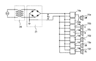
図3には、以上説明した実施形態の変形例を示す。この場合は、音声増幅器として7つの音声増幅器14a〜14gを設けている。そして、ウーハー用のスピーカ15aには、音声増幅器14a及び14bが接続されており、スピーカ15b〜15fには、それぞれ音声増幅器14c〜14gが1つずつ接続されている。そして、音声増幅器14a〜14gは、単一の電源回路より電圧Vccが供給される。ウーハー用スピーカ15aには、2つの音声増幅器14a及び14bから入力されるため、他のスピーカよりも大きな最大出力に設定することができる。したがって、上述した実施形態と同様に電源回路の簡略化等の効果を奏する。
FIG. 3 shows a modification of the embodiment described above. In this case, seven
以上のように、各音声増幅器は、同一の電源電圧が供給されるため、同一の基板上に設置される。そして、その基板にすべての音声増幅器の放熱を行う共通の放熱板を取り付ければよい。したがって、異なる電圧が供給される場合に設けなければならない絶縁シートといった絶縁構造が不要となる。そして、電源回路も1つで済み、また放熱板も共通化できるため、部品点数の削減、基板面積の縮小といったコンパクト化が可能となる。 As described above, since the same power supply voltage is supplied to each audio amplifier, they are installed on the same substrate. A common heat radiating plate for radiating heat from all the audio amplifiers may be attached to the substrate. Therefore, an insulating structure such as an insulating sheet that must be provided when different voltages are supplied is not necessary. Since only one power supply circuit is required and a heat sink can be used in common, it is possible to reduce the number of components and the board area.
なお、上記実施形態では、電源回路としてトランス電源を例に説明したが、スイッチング電源についても同様に用いることができる。 In the above embodiment, the transformer power supply is described as an example of the power supply circuit, but the switching power supply can be used in the same manner.
10 信号切換回路
11 制御回路
12 サラウンド処理回路
13 スイッチ回路
14 音声増幅器
15 スピーカ
10 Signal switching circuit
11 Control circuit
12 Surround processing circuit
13 Switch circuit
14 Audio amplifier
15 Speaker
Claims (3)
Priority Applications (1)
| Application Number | Priority Date | Filing Date | Title |
|---|---|---|---|
| JP2003354235A JP2005123747A (en) | 2003-10-14 | 2003-10-14 | Audio reproducing apparatus |
Applications Claiming Priority (1)
| Application Number | Priority Date | Filing Date | Title |
|---|---|---|---|
| JP2003354235A JP2005123747A (en) | 2003-10-14 | 2003-10-14 | Audio reproducing apparatus |
Publications (1)
| Publication Number | Publication Date |
|---|---|
| JP2005123747A true JP2005123747A (en) | 2005-05-12 |
Family
ID=34612264
Family Applications (1)
| Application Number | Title | Priority Date | Filing Date |
|---|---|---|---|
| JP2003354235A Pending JP2005123747A (en) | 2003-10-14 | 2003-10-14 | Audio reproducing apparatus |
Country Status (1)
| Country | Link |
|---|---|
| JP (1) | JP2005123747A (en) |
Cited By (3)
| Publication number | Priority date | Publication date | Assignee | Title |
|---|---|---|---|---|
| JP2007282151A (en) * | 2006-04-12 | 2007-10-25 | Sharp Corp | Audio system |
| JP2009253926A (en) * | 2008-04-11 | 2009-10-29 | Mitsubishi Electric Corp | Sound output amplification system |
| JP2011019138A (en) * | 2009-07-10 | 2011-01-27 | Seiko Npc Corp | Sound processing circuit and speaker system |
-
2003
- 2003-10-14 JP JP2003354235A patent/JP2005123747A/en active Pending
Cited By (3)
| Publication number | Priority date | Publication date | Assignee | Title |
|---|---|---|---|---|
| JP2007282151A (en) * | 2006-04-12 | 2007-10-25 | Sharp Corp | Audio system |
| JP2009253926A (en) * | 2008-04-11 | 2009-10-29 | Mitsubishi Electric Corp | Sound output amplification system |
| JP2011019138A (en) * | 2009-07-10 | 2011-01-27 | Seiko Npc Corp | Sound processing circuit and speaker system |
Similar Documents
| Publication | Publication Date | Title |
|---|---|---|
| JP4258472B2 (en) | Loudspeaker system | |
| KR20100134656A (en) | Sound system and method of operation therefor | |
| JP2006067218A (en) | Audio reproducing device | |
| JP2002369283A (en) | Earphone | |
| CN201590835U (en) | High-fidelity sound reproduction system | |
| JP2010068409A (en) | Sound emitting apparatus | |
| CN101027939A (en) | Multi-channel audio control | |
| WO2005089018A1 (en) | Stereophonic reproducing system and stereophonic reproducing device | |
| JP2005123747A (en) | Audio reproducing apparatus | |
| KR20090001928A (en) | Apparatus for sounder for multimedia lecture | |
| KR100386919B1 (en) | Karaoke Apparatus | |
| JP5671686B2 (en) | Sound playback device | |
| JP2002135883A (en) | On-vehicle audio interface adapter | |
| JP6722973B1 (en) | Surround circuit and acoustic system using the surround circuit | |
| JP6127782B2 (en) | Audio signal amplifier | |
| JP6569165B1 (en) | Surround circuit and acoustic system using the surround circuit | |
| JP2013500615A (en) | Audio playback system | |
| JPWO2005064991A1 (en) | Audio equipment | |
| JPH0937381A (en) | Output level switching circuit | |
| JP2007081812A (en) | Electronic musical-sound generator having power-saving function | |
| JP2001202157A (en) | Portable information processor with a plurality of loudspeakers | |
| US20010031057A1 (en) | Method and apparatus for producing spatially distributed sound into a set of headphones | |
| JP5498732B2 (en) | Audio processing circuit and speaker system | |
| RU2260254C2 (en) | Sound-reproducing earphone device | |
| KR200278839Y1 (en) | Woofer speaker |
Legal Events
| Date | Code | Title | Description |
|---|---|---|---|
| A621 | Written request for application examination |
Free format text: JAPANESE INTERMEDIATE CODE: A621 Effective date: 20060105 |
|
| A977 | Report on retrieval |
Free format text: JAPANESE INTERMEDIATE CODE: A971007 Effective date: 20080421 |
|
| A131 | Notification of reasons for refusal |
Free format text: JAPANESE INTERMEDIATE CODE: A131 Effective date: 20080507 |
|
| A02 | Decision of refusal |
Free format text: JAPANESE INTERMEDIATE CODE: A02 Effective date: 20080909 |