JP2005123744A - COMMUNICATION SYSTEM, COMMUNICATION DEVICE, COMMUNICATION METHOD, PROGRAM, AND PROGRAM RECORDING MEDIUM - Google Patents
COMMUNICATION SYSTEM, COMMUNICATION DEVICE, COMMUNICATION METHOD, PROGRAM, AND PROGRAM RECORDING MEDIUM Download PDFInfo
- Publication number
- JP2005123744A JP2005123744A JP2003354206A JP2003354206A JP2005123744A JP 2005123744 A JP2005123744 A JP 2005123744A JP 2003354206 A JP2003354206 A JP 2003354206A JP 2003354206 A JP2003354206 A JP 2003354206A JP 2005123744 A JP2005123744 A JP 2005123744A
- Authority
- JP
- Japan
- Prior art keywords
- packet
- communication
- host controller
- unit
- answer
- Prior art date
- Legal status (The legal status is an assumption and is not a legal conclusion. Google has not performed a legal analysis and makes no representation as to the accuracy of the status listed.)
- Withdrawn
Links
Images
Landscapes
- Data Exchanges In Wide-Area Networks (AREA)
- Small-Scale Networks (AREA)
Abstract
Description
本発明は、通信システム、通信装置および通信方法、並びにプログラムおよびプログラム記録媒体に関し、特に、ブロードキャストにより、複数ノードから情報を短時間で取得することができるようにする通信システム、通信装置および通信方法、並びにプログラムおよびプログラム記録媒体に関する。 The present invention relates to a communication system, a communication device, a communication method, a program, and a program recording medium, and in particular, a communication system, a communication device, and a communication method that enable information to be acquired from a plurality of nodes in a short time by broadcasting. And a program and a program recording medium.
例えば、ロボットにおいては、その内蔵するホストコントローラが、各部のアクチュエータに指令を送信することにより、アクチュエータが駆動する。これにより、ロボットは、各種の行動を起こす。このようなロボットにおいて、ホストコントローラは、アクチュエータに設けられた制御回路との間で、指令その他を送受信する通信を行なう。従って、ロボットにおいては、ホストコントローラと多数の制御回路とによって、通信システムが構成されている。いま、ホストコントローラと通信する通信相手である制御回路をノードと呼ぶこととすると、ホストコントローラとノードとの間では、例えば、図1に示すようにして通信が行なわれる。 For example, in a robot, the built-in host controller transmits a command to the actuator of each unit, whereby the actuator is driven. As a result, the robot performs various actions. In such a robot, the host controller performs communication for transmitting / receiving commands and the like to / from a control circuit provided in the actuator. Therefore, in the robot, a communication system is configured by the host controller and a large number of control circuits. Now, assuming that a control circuit that is a communication partner communicating with the host controller is called a node, communication is performed between the host controller and the node, for example, as shown in FIG.
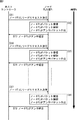
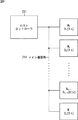
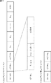
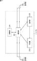
図1は、従来のロボットの内部に構成されている通信システムにおいて、ホストコントローラが、すべてのノードP1乃至Pnから情報を取得する処理の流れを示している。ここで、ノードP1乃至Pnは、インテリジェントな機能を備えており、例えば、パケットの受信、パケットに格納されたデータの解析、パケットの作成、および作成したパケットの送信が可能である。さらに、ノードP1乃至Pnは、アクチュエータの状態の情報であるデータ#0乃至#nを保持しているものとする。
FIG. 1 shows a flow of processing in which a host controller acquires information from all nodes P 1 to P n in a communication system configured inside a conventional robot. Here, the nodes P 1 to P n have an intelligent function, and can receive a packet, analyze data stored in the packet, create a packet, and transmit the created packet, for example. Further, it is assumed that the nodes P 1 to P n hold
ホストコントローラが、すべてのノードP1乃至PnからノードPi(i=1,2,・・・,n)それぞれが保持しているアクチュエータの状態の情報としてのデータ#1乃至#nを取得する場合、例えば、次のような処理を行なう。まず最初に、ステップS11において、ホストコントローラは、ノードP1へ、情報を要求するパケットであるリードリクエストパケットを送信する。ステップS11の後、ステップS12において、ノードP1は、ホストコントローラが送信したリードリクエストパケットを受信し、そのリードリクエストパケットに格納されている要求の内容を解析する。さらに、ノードP1は、ホストコントローラからの要求に応答するパケットである、ノードP1が保持しているデータ#1を格納したアンサパケットを作成し、ステップS12からステップS13に進む。ステップS13において、ノードP1は、ステップS12で作成したアンサパケットを、ホストコントローラへ送信する。これにより、ホストコントローラは、ノードP1が保持していた情報、即ち、ここでは、データ#1を取得する。
The host controller obtains
さらに、ホストコントローラは、ノードP2乃至PnにおいてもノードP1と同様な処理を行う。即ち、ステップS13からステップS14に進み、ホストコントローラは、ノードP2へリードリクエストパケットを送信する。ノードP2は、ステップS15において、ホストコントローラが送信したリードリクエストパケットを受信し、そのリードリクエストパケットに格納されている要求の内容を解析して、自身が保持しているデータ#2を格納したアンサパケットを作成する。ノードP2は、ステップS16において、ステップS15で作成したアンサパケットをホストコントローラへ送信する。これにより、ホストコントローラは、ノードP2が保持していたデータ#2を取得する。以下同様に処理を行い、ホストコントローラは、ステップS17で、最後のノードであるノードPnへリードリクエストパケットを送信する。そして、ステップS17からステップS18に進み、ノードPnは、ホストコントローラからのリードリクエストパケットを受信し、そのリードリクエストパケットに格納されている要求の内容を解析して、自身が保持しているデータ#nを格納したアンサパケットを作成する。ノードPnは、ステップS19において、ステップS18で作成したアンサパケットをホストコントローラへ送信する。これにより、ホストコントローラは、ノードPnが保持していたデータ#nを取得する。
Further, the host controller performs the same processing as that of the node P 1 in the nodes P 2 to P n . That is, the process proceeds from step S13 to step S14, the host controller transmits a read request packet to the node P 2. In step S15, the node P 2 receives the read request packet transmitted from the host controller, analyzes the content of the request stored in the read request packet, and stores the
このように、ホストコントローラは、情報を取得するノードをひとつずつ指定し、指定したノード宛にリードリクエストパケットを送信し、そのノードからアンサパケットを受信する処理を繰り返すことにより、すべてのノードから情報を取得する。(非特許文献1参照) In this way, the host controller designates each node from which information is to be acquired one by one, transmits a read request packet to the designated node, and repeats the process of receiving an answer packet from that node, thereby obtaining information from all nodes. To get. (See Non-Patent Document 1)
しかしながら、従来の通信システムでは、ノードP1乃至Pnから情報を取得する場合、ホストコントローラは、n個のノードP1乃至Pnに対して、n個のリードリクエストパケットを送信する。そして、ノードP1乃至Pnは、ホストコントローラが送信したリードリクエストパケットをそれぞれ解析する。そのため、特に、多数のノードから情報を取得するまでに多くの時間がかかった。 However, in the conventional communication system, when acquiring information from the nodes P 1 to P n , the host controller transmits n read request packets to the n nodes P 1 to P n . Then, each of the nodes P 1 to P n analyzes the read request packet transmitted by the host controller. Therefore, it took a lot of time to acquire information from a large number of nodes.
本発明はこのような状況に鑑みてなされたものであり、ホストコントローラが、複数のノードから情報を短時間で取得することを目的としている。 The present invention has been made in view of such a situation, and it is an object of the host controller to acquire information from a plurality of nodes in a short time.
本発明の通信システムのホストコントローラは、ノードに対して情報を要求するパケットであるリードリクエストパケットをブロードキャストするブロードキャスト手段を備え、複数のノードそれぞれは、リードリクエストパケットを受信する受信手段と、リードリクエストパケットに応答するアンサパケットを作成する作成手段と、作成手段が作成したアンサパケットを所定の順番で送信する送信手段とを備えることを特徴とする。 The host controller of the communication system of the present invention includes a broadcast unit that broadcasts a read request packet that is a packet for requesting information to a node, and each of the plurality of nodes includes a receiving unit that receives the read request packet, and a read request It is characterized by comprising creation means for creating an answer packet in response to a packet and transmission means for sending the answer packets created by the creation means in a predetermined order.
本発明の通信装置は、ホストコントローラによってブロードキャストされる、情報を要求するパケットであるリードリクエストパケットを受信する受信手段と、リードリクエストパケットに応答するアンサパケットを作成する作成手段と、作成手段が作成したアンサパケットを所定の順番で送信する送信手段とを備えることを特徴とする。 The communication apparatus of the present invention includes a receiving unit that receives a read request packet that is a packet requesting information broadcast by a host controller, a creating unit that creates an answer packet in response to the read request packet, and a creating unit creates And transmitting means for transmitting the received answer packets in a predetermined order.
本発明の通信装置は、アンサパケットを送信する順番を記憶する記憶手段をさらに設け、送信手段には、アンサパケットを、記憶手段に記憶された順番で送信させるようにすることができる。 The communication apparatus according to the present invention can further include a storage unit that stores the order in which the answer packets are transmitted, and the transmission unit can transmit the answer packets in the order stored in the storage unit.
受信手段には、他の通信装置が送信したアンサパケットをさらに受信させ、送信手段には、自身のアンサパケットを送信すべき順番の1つ前に送信されるべき順番のアンサパケットが受信手段において受信された後、自身のアンサパケットを送信させるようにすることができる。 The receiving unit further receives an answer packet transmitted by another communication device, and the transmitting unit receives the answer packet in the order to be transmitted one order before the order in which the answer packet is to be transmitted. After being received, it is possible to transmit its own answer packet.
送信手段には、ホストコントローラに対して、自身の直後に接続されている他の通信装置がアンサパケットを送信した後、自身のアンサパケットを送信させるようにすることができる。 The transmission means can cause the host controller to transmit its own answer packet after another communication apparatus connected immediately after itself transmits the answer packet.
ホストコントローラから複数の通信装置への方向を下り方向とするとともに、複数の通信装置からホストコントローラの方向を上り方向として、受信手段には、下り方向のパケットを受信した後、上り方向のパケットを受信する状態に切り替えさせ、送信手段には、下り方向にパケットを送信した後、上り方向にパケットを送信する状態に切り替えさせることができる。 The direction from the host controller to the plurality of communication devices is the downlink direction, the direction of the host controller from the plurality of communication devices is the uplink direction, and the receiving means receives the downlink packet and then receives the uplink packet. The transmission unit can be switched to a reception state, and the transmission unit can be switched to a state in which the packet is transmitted in the upstream direction after the packet is transmitted in the downstream direction.
ホストコントローラから複数の通信装置への方向を下り方向とするとともに、複数の通信装置からホストコントローラの方向を上り方向として、受信手段には、上り方向と下り方向のパケットを受信させ、送信手段には、上り方向と下り方向にパケットを送信させることができる。 The direction from the host controller to the plurality of communication devices is the downlink direction, the direction of the host controller from the plurality of communication devices is the uplink direction, the reception means receives the packets in the uplink and the downlink directions, and the transmission means Can transmit packets in the upstream and downstream directions.
本発明の通信方法は、ホストコントローラによってブロードキャストされる、情報を要求するパケットであるリードリクエストパケットを受信する受信ステップと、リードリクエストパケットに応答するアンサパケットを作成する作成ステップと、作成ステップが作成したアンサパケットを所定の順番で送信する送信ステップとを含むことを特徴とする。 The communication method of the present invention includes a reception step for receiving a read request packet that is a packet requesting information broadcast by a host controller, a creation step for creating an answer packet in response to the read request packet, and a creation step And a transmission step of transmitting the answer packets in a predetermined order.
本発明のプログラムは、ホストコントローラによってブロードキャストされる、情報を要求するパケットであるリードリクエストパケットを受信させる受信ステップと、リードリクエストパケットに応答するアンサパケットを作成させる作成ステップと、作成ステップが作成したアンサパケットを所定の順番で送信させる送信ステップとをコンピュータに実行させる。 The program of the present invention is created by a reception step for receiving a read request packet that is a packet requesting information broadcast by a host controller, a creation step for creating an answer packet in response to the read request packet, and a creation step. And causing the computer to execute a transmission step of transmitting the answer packets in a predetermined order.
本発明の記録媒体のプログラムは、ホストコントローラによってブロードキャストされる、情報を要求するパケットであるリードリクエストパケットを受信させる受信ステップと、リードリクエストパケットに応答するアンサパケットを作成させる作成ステップと、作成ステップが作成したアンサパケットを所定の順番で送信させる送信ステップとを含むことを特徴とする。 The recording medium program of the present invention includes a reception step for receiving a read request packet, which is a packet requesting information, broadcast by a host controller, a creation step for creating an answer packet in response to the read request packet, and a creation step Including a transmission step of transmitting the created answer packets in a predetermined order.
本発明の通信システム、通信装置、通信方法、プログラム、およびプログラム記録媒体に記録されているプログラムにおいては、ホストコントローラによってブロードキャストされる、情報を要求するパケットであるリードリクエストパケットが受信され、リードリクエストパケットに応答するアンサパケットが作成され、作成されたアンサパケットが所定の順番で送信される。 In the communication system, the communication apparatus, the communication method, the program, and the program recorded in the program recording medium of the present invention, a read request packet that is a packet for requesting information that is broadcast by the host controller is received. An answer packet in response to the packet is created, and the created answer packet is transmitted in a predetermined order.
本発明によれば、複数の通信装置から情報を短時間で取得することができる。 According to the present invention, information can be acquired from a plurality of communication devices in a short time.
以下に本発明の実施の形態を説明するが、特許請求の範囲に記載の構成要件と、本発明の実施の形態における具体例との対応関係を例示すると、次のようになる。この記載は、特許請求の範囲に記載されている発明をサポートする具体例が、発明の実施の形態に記載されていることを確認するためのものである。従って、発明の実施の形態中には記載されているが、構成要件に対応するものとして、ここには記載されていない具体例があったとしても、そのことは、その具体例が、その構成要件に対応するものではないことを意味するものではない。逆に、具体例が構成要件に対応するものとしてここに記載されていたとしても、そのことは、その具体例が、その構成要件以外の構成要件には対応しないものであることを意味するものでもない。 Embodiments of the present invention will be described below. Correspondences between constituent elements described in the claims and specific examples in the embodiments of the present invention are exemplified as follows. This description is intended to confirm that specific examples supporting the invention described in the claims are described in the embodiments of the invention. Therefore, even if there are specific examples that are described in the embodiment of the invention but are not described here as corresponding to the configuration requirements, the specific examples are not included in the configuration. It does not mean that it does not correspond to a requirement. On the contrary, even if a specific example is described here as corresponding to a configuration requirement, this means that the specific example does not correspond to a configuration requirement other than the configuration requirement. not.
さらに、この記載は、発明の実施の形態に記載されている具体例に対応する発明が、特許請求の範囲にすべて記載されていることを意味するものではない。換言すれば、この記載は、発明の実施の形態に記載されている具体例に対応する発明であって、この出願の特許請求の範囲には記載されていない発明の存在、すなわち、将来、分割出願されたり、補正により追加されたりする発明の存在を否定するものではない。 Further, this description does not mean that all the inventions corresponding to the specific examples described in the embodiments of the invention are described in the claims. In other words, this description is an invention corresponding to the specific example described in the embodiment of the invention, and is the existence of an invention not described in the claims of this application, that is, in the future. It does not deny the existence of an invention that has been applied for or added by amendment.
請求項1に記載の通信システムは、
ホストコントローラと複数のノードとが、パケットによる通信を行なう通信システムであって、
前記ホストコントローラは、前記ノードに対して情報を要求するパケットであるリードリクエストパケットをブロードキャストするブロードキャスト手段(例えば、図14のステップS61の処理)を備え、
前記複数のノードそれぞれは、
前記リードリクエストパケットを受信する受信手段(例えば、図15のステップS71の処理)と、
前記リードリクエストパケットに応答するアンサパケットを作成する作成手段(例えば、図15のステップS72の処理)と、
前記作成手段が作成したアンサパケットを所定の順番で送信する送信手段(例えば、図15のステップS76の処理)と
を備える
ことを特徴とする。
The communication system according to
A communication system in which a host controller and a plurality of nodes perform communication using packets,
The host controller includes broadcast means for broadcasting a read request packet that is a packet for requesting information to the node (for example, the process of step S61 in FIG. 14),
Each of the plurality of nodes
Receiving means for receiving the read request packet (for example, the process of step S71 of FIG. 15);
Creating means for creating an answer packet in response to the read request packet (for example, the process of step S72 in FIG. 15);
Transmitting means for transmitting the answer packets created by the creating means in a predetermined order (for example, processing in step S76 in FIG. 15).
請求項2に記載の通信装置は、
ホストコントローラとの間で、パケットによる通信を行なう複数の通信装置のうちの1つの通信装置であって、
前記ホストコントローラによってブロードキャストされる、情報を要求するパケットであるリードリクエストパケットを受信する受信手段(例えば、図15のステップS71の処理)と、
前記リードリクエストパケットに応答するアンサパケットを作成する作成手段(例えば、図15のステップS72の処理)と、
前記作成手段が作成したアンサパケットを所定の順番で送信する送信手段(例えば、図15のステップS76の処理)と
を備える
ことを特徴とする。
The communication device according to
One communication device among a plurality of communication devices that perform packet communication with the host controller,
Receiving means for receiving a read request packet, which is a packet requesting information, broadcast by the host controller (for example, the process of step S71 in FIG. 15);
Creating means for creating an answer packet in response to the read request packet (for example, the process of step S72 in FIG. 15);
Transmitting means for transmitting the answer packets created by the creating means in a predetermined order (for example, processing in step S76 in FIG. 15).
請求項3に記載の通信装置は、
前記アンサパケットを送信する順番を記憶する記憶手段(例えば、図12の記憶部274)をさらに備え、
前記送信手段は、前記アンサパケットを、前記記憶手段に記憶された順番で送信する
ことを特徴とする。
The communication device according to
It further comprises storage means for storing the order in which the answer packets are transmitted (for example, the
The transmission means transmits the answer packets in the order stored in the storage means.
請求項9に記載の通信方法は、
ホストコントローラとの間で、パケットによる通信を行なう複数の通信装置のうちの1つの通信装置における通信方法であって、
前記ホストコントローラによってブロードキャストされる、情報を要求するパケットであるリードリクエストパケットを受信する受信ステップ(例えば、図15のステップS71の処理)と、
前記リードリクエストパケットに応答するアンサパケットを作成する作成ステップ(例えば、図15のステップS72の処理)と、
前記作成ステップが作成したアンサパケットを所定の順番で送信する送信ステップ(例えば、図15のステップS76の処理)と
を含む
ことを特徴とする。
The communication method according to claim 9,
A communication method in one communication device among a plurality of communication devices that perform packet communication with a host controller,
A receiving step of receiving a read request packet, which is a packet requesting information, broadcast by the host controller (for example, the process of step S71 in FIG. 15);
A creation step for creating an answer packet in response to the read request packet (for example, the process of step S72 in FIG. 15);
A transmission step (for example, the process of step S76 in FIG. 15) for transmitting the answer packets created in the creation step in a predetermined order.
請求項10に記載のプログラムの各ステップおよび請求項11に記載のプログラム記録媒体に記録されているプログラムの各ステップと、発明の実施の形態との対応関係は、請求項9に記載の通信装置と同様である。
The correspondence relationship between each step of the program according to claim 10 and each step of the program recorded in the program recording medium according to
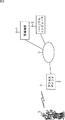
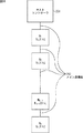
図2は、本発明を適用したロボット5の利用例を示している。
FIG. 2 shows an example of use of the
ユーザからの指令や周囲の環境に応じて自主的に行動を決定する人間型のロボット5は、IEEE(Institute of Electrical and Electronic Engineers)802.11b規格に準拠して、アクセスポイント2と通信し、例えば、ネットワーク3を介して、家電機器4−1を制御したり、パーソナルコンピュータ4−2からのコマンドを受信したりして所定の処理を行う。
A
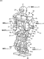
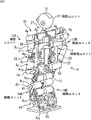
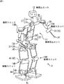
図3は、本発明を適用した2足歩行型のロボット5の正面方向の斜視図であり、図4は、ロボット5の背面方向からの斜視図である。また、図5は、ロボット5の軸構成について説明するための図である。
3 is a front perspective view of the
ロボット5は、胴体部ユニット11、胴体部ユニット11の上部に配設された頭部ユニット12、胴体部ユニット11の上部左右の所定位置に取り付けられた腕部ユニット13Aおよび腕部ユニット13B、並びに胴体部ユニット11の下部左右の所定位置に取り付けられた脚部ユニット14Aおよび脚部ユニット14Bにより構成されている。
The
胴体部ユニット11は、体幹上部を形成するフレーム21および体幹下部を形成する腰ベース22が腰関節機構23を介して連結することにより構成されている。胴体部ユニット11は、体幹下部の腰ベース22に固定された腰関節機構23のアクチュエータA1、および、アクチュエータA2がそれぞれ駆動することによって、体幹上部を、図5に示す直交するロール軸24およびピッチ軸25の回りに、それぞれ独立に回転させることができるようになされている。
The
頭部ユニット12は、フレーム21の上端に固定された肩ベース26の上面中央部に首関節機構27を介して取り付けられており、首関節機構27のアクチュエータA3、およびアクチュエータA4がそれぞれ駆動することによって、図5に示す直交するピッチ軸28およびヨー軸29の回りに、それぞれ独立に回転させることができるようになされている。
The
腕部ユニット13A、および腕部ユニット13Bは、肩関節機構30を介して肩ベース26の左右にそれぞれ取り付けられており、対応する肩関節機構30のアクチュエータA5およびアクチュエータA6、並びに、アクチュエータA21およびアクチュエータA22がそれぞれ駆動することによって、図5に示す、直交するピッチ軸31およびロール軸32の回りに、それぞれを独立に回転させることができるようになされている。
The
この場合、腕部ユニット13A、および腕部ユニット13Bは、上腕部を形成するアクチュエータA7、およびアクチュエータA23の出力軸に、肘関節機構44を介して、前腕部を形成するアクチュエータA8、およびアクチュエータA24が連結され、前腕部の先端に手部34が取り付けられることにより構成されている。
In this case, the
そして腕部ユニット13A、および腕部ユニット13Bでは、アクチュエータA7、およびアクチュエータA23が駆動することによって、前腕部を図5に示すヨー軸35に対して回転させることができ、アクチュエータA8、およびアクチュエータA24が駆動することによって、前腕部を図5に示すピッチ軸36に対して回転させることができるようになされている。
Then the
脚部ユニット14A、および脚部ユニット14Bは、股関節機構37を介して、体幹下部の腰ベース22にそれぞれ取り付けられており、対応する股関節機構37のアクチュエータA9乃至A11、並びに、アクチュエータA15乃至A17がそれぞれ駆動することによって、図5に示す、互いに直交するヨー軸38、ロール軸39、およびピッチ軸40に対して、それぞれ独立に回転させることができるようになされている。
The
脚部ユニット14A、および、脚部ユニット14Bにおいては、大腿部を形成するフレーム41の下端が、膝関節機構42を介して、下腿部を形成するフレーム43に連結されるとともに、フレーム43の下端が、足首関節機構44を介して、足部45に連結されている。
In the
これにより脚部ユニット14A、および脚部ユニット14Bにおいては、膝関節機構42を形成するアクチュエータA12、およびアクチュエータA18が駆動することによって、図5に示すピッチ軸46に対して、下腿部を回転させることができ、また足首関節機構44のアクチュエータA13およびアクチュエータA14、並びに、アクチュエータA19およびアクチュエータA20がそれぞれ駆動することによって、図5に示す直交するピッチ軸47およびロール軸48に対して、足部45をそれぞれ独立に回転させることができるようになされている。
As a result, in the
脚部ユニット14A、および脚部ユニット14Bの、足部45の足底面(床と接する面)には、それぞれ足底センサ91(図7)が配設されており、足底センサ91のオン・オフに基づいて、足部45が床に接地しているか否かが判別される。
A foot sensor 91 (FIG. 7) is disposed on the bottom surface of the foot 45 (the surface in contact with the floor) of each of the
また、胴体部ユニット11の体幹下部を形成する腰ベース22の背面側には、後述するメイン制御部61(図6)などを内蔵したボックスである、制御ユニット52が配設されている。
In addition, a
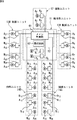
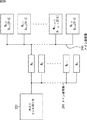
図6は、ロボット5のアクチュエータとその制御系等について説明する図である。
FIG. 6 is a diagram for explaining the actuator of the
胴体部ユニット11に設けられた制御ユニット52には、ロボット5全体の動作制御をつかさどるメイン制御部61、並びに、後述するD/A変換部101、A/D変換部102、バッテリ103、バッテリセンサ131、加速度センサ132、通信部105、および外部メモリ106(いずれも図7)等を含む周辺回路62が収納されている。
A
そしてこの制御ユニット52は、各構成ユニット(胴体部ユニット11、頭部ユニット12、腕部ユニット13、脚部ユニット14)内にそれぞれ配設されたサブ制御部であるノードN1乃至N24と通信路を介して接続されており、ノードN1乃至N24に対して必要な電源電圧を供給したり、ノードN1乃至N24とパケット通信などを行う。
The
ここで、ノードN1乃至N24は、関節機構等であるアクチュエータA1乃至A24を制御するインテリジェントな機能を備えたサブ制御部であり、対応するアクチュエータA1乃至A14と接続されている。また、ノードN1乃至N24は、メイン制御部61から供給された各種信号に基づいて、対応するアクチュエータA1乃至A24を、指定された状態に個々に駆動させるように制御したり、ノードN1乃至N24それぞれが保持しているアクチュエータA1乃至A24のデータをメイン制御部61へ送信したりする。
Here, the nodes N 1 to N 24 are sub-control units having an intelligent function for controlling the actuators A 1 to A 24 that are joint mechanisms and the like, and are connected to the corresponding actuators A 1 to A 14 . . Further, the nodes N 1 to N 24 are controlled based on various signals supplied from the
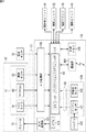
図7は、ロボット5の内部構成を示すブロック図である。
FIG. 7 is a block diagram showing the internal configuration of the
頭部ユニット12には、このロボット5の「目」として機能するCCD(Charge Coupled Device)カメラ81、「耳」として機能するマイクロフォン82、頭部センサ51などからなる外部センサ部71、および、「口」として機能するスピーカ72となどがそれぞれ所定位置に配設され、制御ユニット52内には、バッテリセンサ131および加速度センサ132などからなる内部センサ部104が配設されている。また、脚部ユニット14A、および脚部ユニット14Bの足部45の足底面には、このロボット5の「体勢感覚」の1つとして機能する足底センサ91が配設されている。
The
そして、外部センサ部71のCCDカメラ81は、周囲の状況を撮像し、得られた画像信号を、A/D変換部102を介して、メイン制御部61に送出する。マイクロフォン82は、ユーザから音声入力として与えられる「歩け」、「とまれ」または「右手を挙げろ」等の各種命令音声を集音し、得られた音声信号を、A/D変換部102を介して、メイン制御部61に送出する。
Then, the
また、頭部センサ51は、例えば、図3および図4に示されるように頭部ユニット12の上部に設けられており、ユーザからの「撫でる」や「叩く」といった物理的な働きかけにより受けた圧力を検出し、検出結果としての圧力検出信号を、A/D変換部102を介して、メイン制御部61に送出する。
Further, the
足底センサ91は、足部45の足底面に配設されており、足部45が床に接地している場合、接地信号を、A/D変換部102を介して、メイン制御部61に送出する。メイン制御部61は、接地信号に基づいて、足部45が床に接地しているか否かを判定する。足底センサ91は、脚部ユニット14A、および脚部ユニット14Bの両方の足部45に配設されているため、メイン制御部61は、接地信号に基づいて、ロボット5の両足が床に接地しているか、片足が床に接地しているか、両足とも床に接地していないかを判定することができる。
The
制御ユニット52は、メイン制御部61、D/A変換部101、A/D変換部102、バッテリ103、内部センサ部104、通信部105、および外部メモリ106等により構成される。
The
D/A(Digital/Analog)変換部101は、メイン制御部61から供給されるデジタル信号をD/A変換することによりアナログ信号とし、スピーカ72に供給する。A/D(Analog/ Digital)変換部102は、CCDカメラ81、マイクロフォン82、頭部センサ51、および足底センサ91が出力するアナログ信号をA/D変換することによりデジタル信号とし、メイン制御部61に供給する。
A D / A (Digital / Analog)
内部センサ部104のバッテリセンサ131は、バッテリ103のエネルギ残量を所定の周期で検出し、検出結果をバッテリ残量検出信号として、メイン制御部61に送出する。加速度センサ132は、ロボット5の移動について、3軸方向(x軸、y軸、およびz軸)の加速度を、所定の周期で検出し、検出結果を、加速度検出信号として、メイン制御部61に送出する。
The
メイン制御部61は、メイン制御部61全体の動作を制御するCPU(Central Processing Unit)111と、CPU111が各部を制御するために実行するOS(Operating System)121、アプリケーションプログラム122、その他の必要なデータ等が記憶されている内部メモリ112等を内蔵している。
The
メイン制御部61は、外部センサ部71のCCDカメラ81、マイクロフォン82および頭部センサ51からそれぞれ供給される、画像信号、音声信号および圧力検出信号、並びに足底センサ91から供給される接地信号(以下、これらをまとめて外部センサ信号S1と称する)と、内部センサ部104のバッテリセンサ131および加速度センサ132等からそれぞれ供給される、バッテリ残量検出信号および加速度検出信号(以下、これらをまとめて内部センサ信号S2と称する)に基づいて、ロボット5の周囲および内部の状況や、ユーザからの指令、またはユーザからの働きかけの有無などを判断する。
The
そして、メイン制御部61は、ロボット5の周囲および内部の状況や、ユーザからの指令、または、通信部105により受信されたパーソナルコンピュータ4−2からのコマンドと、内部メモリ112に予め格納されているアプリケーションプログラム122、あるいは、そのとき装填されている外部メモリ106に格納されている各種制御パラメータなどに基づいて、ロボット5の行動を決定し、決定結果に基づく制御信号を生成して、対応する各構成ユニット(胴体部ユニット11、頭部ユニット12、腕部ユニット13、脚部ユニット14)に配設されたノードN1乃至N24へ送出する。ノードN1乃至N24は、供給された制御信号に基づいて、アクチュエータA1乃至A24のうち、各ノードNi(i=1,2,・・・,n)に対応するものの駆動を制御する。これにより、ロボット5は、例えば、頭部ユニット12を上下左右に揺動させたり、腕部ユニット13A、あるいは、腕部ユニット13Bを上に挙げたり、脚部ユニット14Aおよび脚部ユニット14Bを交互に駆動させて、歩行するなどの機械的動作を行う。
The
また、メイン制御部61は、必要に応じて、所定の音声信号をスピーカ72に与えることにより、音声信号に基づく音声を外部に出力させる。
Moreover, the
通信部105は、IEEE802.11b規格に準拠して、アクセスポイント2と無線で通信する。これにより、OS121やアプリケーションプログラム122がバージョンアップされたときに、通信部105を介して、そのバージョンアップされたOSやアプリケーションプログラムをダウンロードして、内部メモリ112に記憶させたり、また、所定のコマンドを、通信部105で受信し、CPU111に与えることができるようになっている。
The
外部メモリ106は、例えば、EEPROM(Electrically Erasable Programmable Read-only Memory)等で構成され、胴体部ユニット11に設けられた図示せぬスロットに対して、着脱可能になっている。外部メモリ106には、例えば、後述するような感情モデル等が記憶される。
The
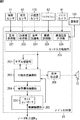
図8は、図7のメイン制御部61の機能的構成例を示している。なお、図8に示す機能的構成は、メイン制御部61が、内部メモリ112に記憶されたOS121およびアプリケーションプログラム122を実行することで実現されるようになっている。また、図8では、D/A変換部101およびA/D変換部102の図示を省略してある。
FIG. 8 shows a functional configuration example of the
メイン制御部61のセンサ入力処理部201は、頭部センサ51、足底センサ91、加速度センサ132、マイクロフォン82、CCDカメラ81、および通信部105からそれぞれ与えられる圧力検出信号、接地信号、加速度検出信号、音声信号、画像信号、および無線信号の通信品質信号等に基づいて、特定の外部状態や、ユーザからの特定の働きかけ、ユーザからの指示等を認識し、その認識結果を表す状態認識情報を、モデル記憶部202および行動決定機構部203に通知する。
The sensor
すなわち、センサ入力処理部201は、圧力処理部221、加速度処理部222、音声認識部223、画像認識部224、および通信品質計測部225を有している。
That is, the sensor
圧力処理部221は、頭部センサ51から与えられる圧力検出信号を処理する。そして、圧力処理部221は、例えば、その処理の結果、所定の閾値以上で、かつ短時間の圧力を検出したときには、「叩かれた(しかられた)」と認識し、所定の閾値未満で、かつ長時間の圧力を検出しなときには、「なでられた(ほめられた)」と認識して、その認識結果を、状態認識情報として、モデル記憶部202および行動決定機構部203に通知する。
The
また、圧力処理部221は、足底センサ91から与えられる接地信号を処理する。そして、圧力処理部221は、例えば、その処理の結果、脚部ユニット14Aの足部45に配設された足底センサ91から接地信号が与えられている場合、脚部ユニット14Aの足部45が床(地面)に接地していると認識し、足底センサ91から接地信号が与えられていない場合、脚部ユニット14Aの足部45が床(地面)に接地していないと認識する。脚部ユニット14Bについても、同様にして、足底センサ91からの接地信号に基づいて、脚部ユニット14Bの足部45が床(地面)に接地しているか否かを認識する。そして、圧力処理部221は、その認識結果を、状態認識情報として、モデル記憶部202および行動決定機構部203に通知する。
Further, the
加速度処理部222は、加速度センサ132から与えられる加速度検出信号に基づいて、胴体部ユニット11の加速度の方向および大きさを、状態認識情報として、モデル記憶部202および行動決定機構部203に通知する。
Based on the acceleration detection signal given from the
音声認識部223は、マイクロフォン82から与えられる音声信号を対象とした音声認識を行う。そして、音声認識部223は、その音声認識結果としての、例えば、「歩け」、「伏せ」、「ボールを追いかけろ」等の単語列を、状態認識情報として、モデル記憶部202および行動決定機構部203に通知する。
The
画像認識部224は、CCDカメラ81から与えられる画像信号を用いて、画像認識処理を行う。そして、画像認識部224は、その処理の結果、例えば、「赤い丸いもの」や、「地面に対して垂直なかつ所定高さ以上の平面」等を検出したときには、「ボールがある」や、「壁がある」等の画像認識結果を、状態認識情報として、モデル記憶部202および行動決定機構部203に通知する。
The
通信品質計測部225は、通信部105から得られるアクセスポイント2からの受信信号に基づいて、通信品質を計測し、その計測結果を、状態認識情報として、行動決定機構部203に通知する。通信品質とは、例えば、ノイズ強度などに対応した無線信号の強度や、エラーレート(スペクトル拡散で広がったバンドの中にバースト的に妨害電波が発生した場合、その通信パケットはエラーとなる)である。
The communication
モデル記憶部202は、ロボット5の感情、本能、成長の状態を表現する感情モデル、本能モデル、成長モデルをそれぞれ記憶し、管理している。
The model storage unit 202 stores and manages an emotion model, an instinct model, and a growth model that express the emotion, instinct, and growth state of the
ここで、感情モデルは、例えば、「うれしさ」、「悲しさ」、「怒り」、「楽しさ」等の感情の状態(度合い)を、所定の範囲(例えば、−1.0乃至1.0等)の値によってそれぞれ表し、センサ入力処理部201からの状態認識情報や時間経過等に基づいて、その値を変化させる。
Here, the emotion model includes, for example, emotion states (degrees) such as “joyfulness”, “sadness”, “anger”, “fun”, etc. within a predetermined range (for example, −1.0 to 1.. 0), and the value is changed based on the state recognition information from the sensor
本能モデルは、例えば、「食欲」、「睡眠欲」、「運動欲」等の本能による欲求の状態(度合い)を、所定の範囲の値によってそれぞれ表し、センサ入力処理部201からの状態認識情報や時間経過等に基づいて、その値を変化させる。
The instinct model represents, for example, the state (degree) of desire by instinct such as “appetite”, “sleep desire”, and “exercise greed” by values in a predetermined range, and state recognition information from the sensor
成長モデルは、例えば、「幼年期」、「青年期」、「熟年期」、「老年期」等の成長の状態(度合い)を、所定の範囲の値によってそれぞれ表し、センサ入力処理部201からの状態認識情報や時間経過等に基づいて、その値を変化させる。
The growth model represents, for example, growth states (degrees) such as “childhood”, “adolescence”, “mature age”, “aged age”, and the like by values within a predetermined range, and from the sensor
モデル記憶部202は、上述のようにして感情モデル、本能モデル、成長モデルの値で表される感情、本能、成長の状態を、状態情報として、行動決定機構部203に送出する。 The model storage unit 202 sends the emotion, instinct, and growth state represented by the values of the emotion model, instinct model, and growth model as described above to the behavior determination mechanism unit 203 as state information.
なお、モデル記憶部202には、センサ入力処理部201から状態認識情報が供給される他に、行動決定機構部203から、ロボット5の現在または過去の行動、具体的には、例えば、「長時間歩いた」などの行動の内容を示す行動情報が供給されるようになっており、モデル記憶部202は、同一の状態認識情報が与えられても、行動情報が示すロボット5の行動に応じて、異なる状態情報を生成するようになっている。
In addition to the state recognition information supplied from the sensor
例えば、ロボット5が、ユーザに挨拶をし、ユーザに頭を撫でられた場合には、ユーザに挨拶をしたという行動情報と、頭を撫でられたという状態認識情報とが、モデル記憶部202に与えられ、この場合、モデル記憶部202では、「うれしさ」を表す感情モデルの値が増加される。
For example, when the
行動決定機構部203は、センサ入力処理部201からの状態認識情報やモデル記憶部202からの状態情報、後述する制御機構部205からのアクチュエータA1乃至A24の状態情報、時間経過等に基づいて、次の行動を決定し、決定された行動の内容を、行動指令情報として、姿勢遷移機構部204に出力する。また、行動決定機構部203は、次の行動が発話である場合、音声合成部208へ発話指令情報を送信する。
Action decision unit 203, based on state information from the state recognition information and the model storage unit 202 from the sensor
姿勢遷移機構部204は、行動決定機構部203から供給される行動指令情報に基づいて、ロボット5の姿勢を、現在の姿勢から次の姿勢に遷移させるための姿勢遷移情報を生成し、これを制御機構部205に送出する。
The posture transition mechanism unit 204 generates posture transition information for changing the posture of the
制御機構部205は、姿勢遷移機構部204からの姿勢遷移情報にしたがって、アクチュエータA1乃至A24を駆動するための制御信号を生成し、これを、アクチュエータA1乃至A24を制御するサブ制御部であり、各構成ユニット(胴体部ユニット11、頭部ユニット12、腕部ユニット13、脚部ユニット14)に配設されたノードN1乃至N24へ送信する。制御信号を受信したノードN1乃至N24は、この制御信号に基づいて、各ノードに接続しているアクチュエータA1乃至A24を駆動し、ロボット5に種々の動作を実行させる。また、制御機構部205は、ノードN1乃至N24から、例えば、アクチュエータA1乃至A24の状態情報を取得し、ロボット5の各関節機構の状態を行動決定機構部203へ通知する。
The control mechanism unit 205 generates a control signal for driving the actuators A 1 to A 24 according to the posture transition information from the posture transition mechanism unit 204, and uses this to generate a sub-control for controlling the actuators A 1 to A 24. And transmitted to nodes N 1 to N 24 arranged in each component unit (
即ち、制御機構部205は、ノードN1乃至N24と通信をするためにホストコントローラ231を有している。ホストコントローラ231は、例えば、制御機構部205が生成した制御信号を、パケットに格納してノードN1乃至N24へ送信したり、また例えば、ノードN1乃至N24が、ホストコントローラ231へ送信したアクチュエータA1乃至A24の情報を含んだパケットを受信して、制御機構部205に各関節機構の状態の情報を供給する。
That is, the control mechanism unit 205 includes a
音声合成部208は、行動決定機構部203から発話指令情報を受信し、その発話指令情報にしたがって、例えば、規則音声合成を行い、合成音をスピーカ72に供給して出力させる。
The
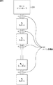
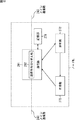
図9は、ホストコントローラ231と、ロボット5の各構成ユニット(胴体部ユニット11、頭部ユニット12、腕部ユニット13、脚部ユニット14)に配設されたノードN1乃至Nnとで構成される通信システムの第1の構成例を示している。
FIG. 9 includes a
図9の通信システムにおいて、ホストコントローラ231とノードN1乃至Nnそれぞれとは、バス型のメイン通信路241を介して通信を行なう。ノードN1乃至Nnは、メイン通信路241を介して並列に接続している。従って、ホストコントローラ231が送信したパケットは、すべてのノードN1乃至Nnへ送信される。また、あるノードNiが送信したパケットは、ホストコントローラ231と他のすべてのノードNj(j=1,2,・・・n、j≠i)とへ送信される。そして、ノードNiは、パケットを受信し、そのパケットの宛先が自分宛であるとき、パケットを処理し、パケットの宛先が自分宛ではないとき、パケットを無視する。
In the communication system of FIG. 9, the
本実施の形態では、ホストコントローラ231は、ブロードキャストにより、リードリクエストパケットを送信する。即ち、ホストコントローラ231は、パケットの宛先に、ブロードキャストである旨の信号であるブロードキャスト信号を格納し、リードリクエストパケットを送信する。すべてのノードN1乃至Nnは、ホストコントローラ231が送信したリードリクエストパケットを受信し、宛先にブロードキャスト信号が格納されているとき、自分宛のパケットであると認識する。これにより、ホストコントローラ231が、1つのリードリクエストパケットをブロードキャストすることにより、すべてのノードN1乃至Nnにおいて、リードリクエストパケットを受信することができる。
In the present embodiment, the
さらに、ノードN1乃至Nnそれぞれは、ホストコントローラ231が送信したリードリクエストパケットを受信した場合、そのリードリクエストパケットに対する応答であるアンサパケットを作成し、所定の順番で、自分のアンサパケットを送信する。即ち、ノードNiは、データDi[0:k]を保持しており、リードリクエストパケットによって、データDi[0:k]が要求された場合には、データDi[0:k]をアンサパケットに配置して送信する。なお、データDi[0:k]は、例えば、データ長がk+1ビットのデータを表す。
Further, when each of the nodes N 1 to N n receives a read request packet transmitted from the
メイン通信路241は、ホストコントローラ231とノードNiとを接続する通信路である。なお、メイン通信路241を介してやりとりする信号は、例えば、電気による信号でも光による信号でもよい。さらに、メイン通信路241を介した通信としては、シリアル通信でも、パラレル通信でも可能である。
The main channel 241 is a communication path connecting the
図10は、ホストコントローラ231が、すべてのノードN1乃至NnからデータD1[0:k]乃至Dn[0:k]を取得するときの処理を説明するフローチャートを示している。
FIG. 10 shows a flowchart for explaining processing when the
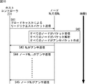
まず最初に、ホストコントローラ231は、ステップS41において、情報の読み出しを要求するリードリクエストパケットを、ブロードキャストで送信して、ステップS42に進む。ステップS42において、ノードN1乃至Nnそれぞれは、ホストコントローラ231から送信されたリードリクエストパケットを受信し、そのリードリクエストパケットを解析する。さらに、すべてのノードN1乃至Nnは、リードリクエストパケットに格納されたデータに対する応答としてのアンサパケットを作成して、ステップS43に進む。
First, in step S41, the
ステップS43において、ノードNnは、ホストコントローラ231へデータDn[0:k]を格納したアンサパケットを送信する。ステップS43からステップS44に進み、ノードNn-1は、ステップS43でノードNnが送信したアンサパケットを受信することにより、ホストコントローラ231に対して自分より1つ前のノードNnがアンサパケットを送信したことを確認し、その後、ホストコントローラ231へデータDn-1[0:k]を格納した自分のアンサパケットを送信する。以下同様に、各ノードNiがノード番号iの降順にアンサパケットを送信し、ステップS45において、ノード番号が1のノードN1が、ホストコントローラ231へデータD1[0:k]を格納したアンサパケットを送信する。これにより、ホストコントローラ231は、すべてのノードN1乃至NnからデータD1[0:k]乃至Dn[0:k]を取得する。
In step S43, the node N n transmits an answer packet storing data D n [0: k] to the
このように、ホストコントローラ231とノードN1乃至Nnとがバス型のメイン通信路241で接続されている通信システムにおいて、ホストコントローラ231がブロードキャストによりリードリクエストを送信する場合、すべてのノードN1乃至Nnは、そのリードリクエストパケットの受信と、アンサパケットの作成を、ほぼ同時に行なうことができる。そのため、図9の通信システムでは、n個のノードN1乃至Nnがリードリクエストパケットを受信してからアンサパケットを作成するまでの時間は、前述した図1の場合と比較すると、理論的にはn分の1に短縮できる。また、図9の通信システムでは、各ノードNiが所定の順番で、即ち、ノード番号の降順にアンサパケットを送信することにより、ノードN1乃至Nnが送信したアンサパケットがホストコントローラ231に集中するのを避けることができる。即ち、アンサパケット同士の衝突などによる、パケットの再送をなくすことができる。
In this way, in the communication system in which the
図11は、図9のホストコントローラ231の機能的構成例を示すブロック図である。ホストコントローラ231は、通信部262と制御部261とから構成されている。さらに、通信部262は、メイン通信路241と接続している。
FIG. 11 is a block diagram illustrating a functional configuration example of the
通信部262は、メイン通信路241を介して、ノードNiとの間でパケットの送信と受信を行なう。即ち、通信部262は、制御部261から供給されたパケットを、ノードNiへ送信する。また、通信部262は、ノードiが送信したホストコントローラ231宛のパケットを受信し、制御部261へ供給する。
The
制御部261は、制御機構部205からノードNiを制御する制御信号を受信し、ノードNiに制御信号などを伝えるためのパケットを作成して、通信部262へ供給する。例えば、制御部261は、制御機構部205から、ノードNiが所持しているアクチュエータAiの情報を取得したい旨の制御信号が供給された場合、リードリクエストパケットを作成して、通信部262へ送信する。また、制御部261は、通信部262が受信したノードNiが送信したパケットを取得し解析して、パケットに格納された、例えば、アクチュエータAiの情報を制御機構部205へ供給する。
Control unit 261 receives a control signal for controlling the node N i from the control mechanism 205 creates a packet for transmitting a control signal to the node N i, and supplies to the
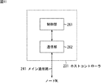
図12は、図9のノードNiの機能的構成例を示すブロック図である。ノードNiは、通信部271、解析部272、作成部273、記憶部274から構成されている。
Figure 12 is a block diagram illustrating a functional configuration example of a node N i in FIG. The node Ni includes a
通信部271は、メイン通信路241に接続されている。通信部271は、ホストコントローラ231や他のノードNjが送信したメイン通信241上のパケットを受信し、そのパケットの種類(Type部)とパケットの宛先(ADDR部)とを解析する。即ち、例えば、受信したパケットが、ホストコントローラ231が送信した自分宛て(ノードNi宛て)のパケットである場合、通信部271は、そのパケットを解析部272へ供給する。また、通信部271は、受信したパケットが、他のノードNjが送信したアンサパケットである場合、そのパケットの送信元を解析する。
The
また、通信部271は、作成部273が作成した、ブロードキャストによるリードリクエストパケットに対する応答としてのアンサパケットを、所定の順番でメイン通信路241を介してホストコントローラ231へ送信する。即ち、例えば、通信部271は、他のノードNjが送信したアンサパケットの送信元と、記憶部274の記憶内容とを適宜比較し、自分がアンサパケットを送信する順番であるかどうかを判定する。そして、通信部271は、自分がアンサパケットを送信する順番であると判定したとき、自分のアンサパケットをホストコントローラ231へ送信する。
In addition, the
解析部272は、通信部271からパケットを受信し、そのパケットを解析する。さらに、解析部272は、パケットの解析結果に基づいて所定の処理を行なう。即ち、例えば、解析部271は、受信したパケットが、ホストコントローラ231が送信したリードリクエストパケットの場合、ノードNiが制御するアクチュエータAiの情報が要求されたことを認識する。この場合、解析部272は、アクチュエータAiの情報を取得して、作成部273へ供給する。
The
作成部273は、ホストコントローラ231へ送信するアンサパケットを作成する。さらに、作成部273は、解析部272から供給された情報をアンサパケットに格納する。また、作成部273は、通信部271へ作成したパケットを供給する。即ち、例えば、解析部272からアクチュエータAiの情報を受信した場合、作成部273は、アクチュエータAiの情報を格納した、ホストコントローラ231宛のアンサパケットを作成する。さらに、作成部273は、作成したアンサパケットを通信部271へ供給する。
The
記憶部274は、例えば、半導体メモリなどで構成され、自分のノード番号であるiを、アンサパケットの送信順として記憶している。通信部271は、他のノードNjが送信したアンサパケットを受信して、アンサパケットの送信元であるノードNjのノード番号jを認識するとともに、記憶部274が記憶している自分のノード番号iを読み取る。そして、通信部271は、受信したアンサパケットの送信元のノード番号jが自分のノード番号iの1つ後の番号であるとき、即ち、j=i+1のとき、自分のアンサパケットをホストコントローラ231へ送信する。
The
図13は、ホストコントローラ231とノードとの間で送受信するパケットのフォーマットを示している。
FIG. 13 shows a format of a packet transmitted / received between the
図13の上図は、コンテンツ付のパケットのフォーマットを示している。例えば、ホストコントローラ231の制御部261は、ノードNiにデータの書き込みを要求する場合、コンテンツ付のパケットのフォーマットを使用して、書き込ませるデータを配置したライトリクエストパケットを作成する。また、例えば、ノードNiの作成部273は、ホストコントローラ231の要求に応じてデータを送信する場合、コンテンツ付のパケットのフォーマットを使用して、要求されたデータを配置したアンサパケットを作成する。
The upper diagram of FIG. 13 shows the format of a packet with content. For example, when requesting the node Ni to write data, the control unit 261 of the
図13の中図は、パケットのCTRL部を示している。 The middle diagram of FIG. 13 shows the CTRL portion of the packet.
図13の下図は、コンテンツ無しのパケットのフォーマットを示している。例えば、ホストコントローラ231の制御部261は、ノードNiのデータを要求する場合、コンテンツ無しのパケットのフォーマットを使用して、リードリクエストパケットを作成する。また、例えば、ホストコントローラ231の制御部261は、ノードNiにUSER'S BITの書き込み等を要求する場合、コンテンツ無しのパケットのフォーマットを使用して、ライトリクエストパケットを送信する。さらに、例えば、ノードNiの作成部273は、ホストコントローラ231の要求に応じる送信すべきデータがない場合、コンテンツ無しのパケットフォーマットを使用して、アンサパケットを送信する。
The lower diagram of FIG. 13 shows the format of a packet without content. For example, the control unit 261 of the
コンテンツ無しのパケットのフォーマットは、コンテンツ付のパケットのフォーマットからユーザデータD1乃至Dn、およびCRC部を省いたパケットのフォーマットであり、その他の各部の構成については同一である。従って、以下の各部の説明においては、コンテンツ付のパケットのフォーマットについて記述する。 The packet format without content is a packet format in which the user data D 1 to D n and the CRC unit are omitted from the format of the packet with content, and the configuration of each other unit is the same. Therefore, in the following description of each part, the format of a packet with content will be described.
パケットは、その先頭から、8ビットの同期信号が配置されるSYNC(Synchronization word)部、パケットの種類やアドレスを格納するCTRL(Control)部、CTRL部のビット列をビット反転したビットが配置されるnCTRL部、ユーザデータ(ペイロード)を格納するコンテンツ部、およびデータのエラーを検出するコードが配置されるCRC部が順次配置されて構成される。 From the head of the packet, a SYNC (Synchronization word) part in which an 8-bit synchronization signal is arranged, a CTRL (Control) part for storing the type and address of the packet, and bits obtained by inverting the bit string of the CTRL part are arranged. An nCTRL part, a content part for storing user data (payload), and a CRC part in which a code for detecting data errors is arranged are sequentially arranged.
CTRL部には、CTRLが格納される。CTRLは、例えば、8ビットで、パケットの種類を表す2ビットのType(タイプ)部、ユーザがアプリケーションで自由に使用する2ビットのUser's Bit(ユーザビット)部、および、パケットの宛先もしくはパケットの送信元を表す4ビットのADDR(アドレス)部で構成されている。 CTRL is stored in the CTRL section. CTRL is, for example, 8 bits, a 2-bit Type part indicating the type of packet, a 2-bit User's Bit (user bit) part that the user can freely use in the application, and the packet destination or packet It consists of a 4-bit ADDR (address) part representing the source.
Type部には、パケットの種類を表すタイプが格納される。即ち、例えば、ホストコントローラ231の制御部261は、ノードNiから情報を取得するリードリクエストパケットを作成する場合、Type部にリードリクエスト信号としての2ビットを格納する。一方、ノードNiの作成部273は、リードリクエストに応答するアンサパケットを作成する場合、Type部にアンサ信号としての2ビットを格納する。また、ホストコントローラ231の制御部261は、ノードNiに制御信号等の情報を書き込むライトリクエストパケットを作成する場合、Type部にライトリクエスト信号としての2ビットを格納する。
In the Type portion, a type indicating the type of packet is stored. That is, for example, the control unit 261 of the
ADDR(Address)部には、パケットの宛先もしくは送信元のアドレスが格納される。即ち、例えば、ホストコントローラ231の制御部261は、ノードNiへパケットを送信する場合、宛先であるノードNiを表す情報としての、例えば、ノード番号iをADDR部に格納する。また、制御部261は、すべてのノードN1乃至Nnへパケットを送信する場合、ブロードキャスト信号としての4ビットをADDR部に格納する。一方、ノードNiの作成部273は、アンサパケットをホストコントローラ231へ送信する場合、送信元である自分を表す情報としての、例えば、ノード番号iをADDR部に格納する。
The ADDR (Address) portion stores the address of the packet destination or the transmission source. That is, for example, the control unit 261 of the
従って、例えば、ノードNiの通信部271は、受信したパケットのType部を解析することにより、受信したパケットがリードリクエストパケットであるか、またはアンサパケットであるかを認識することができる。さらに、例えば、ノードNiの通信部271は、受信したパケットがリードリクエストパケットである場合、ADDR部に自分のノード番号iもしくは、ブロードキャスト信号が格納されているとき、自分宛てのパケットと認識してパケットを受信し、解析部272へ供給する。一方、ノードNiの通信部271は、ADDR部に他のノード番号jが格納されているとき、パケットを無視(破棄)する。また、ノードNiの通信部271は、受信したパケットがアンサパケットである場合、ADDR部を解析して、送信元のノード番号を認識する。
Thus, for example, the
nCTRL部には、CTRL部に配置したビット列をビット反転したビット列であるnCTRLが格納される。従って、nCTRLをビット反転したものと、CTRLとが一致していない場合、CTRLにエラーが生じている可能性がある。 The nCTRL section stores nCTRL which is a bit string obtained by bit-inverting the bit string arranged in the CTRL section. Therefore, if nCTRL bit-inverted and CTRL do not match, CTRL may have an error.
以上のSYNC部、CTRL部、およびnCTRL部がパケットのヘッダを構成している。パケットのヘッダの後には、送信するユーザデータが配置される。 The SYNC section, CTRL section, and nCTRL section described above constitute the packet header. User data to be transmitted is arranged after the header of the packet.
コンテンツ部には、ユーザデータD1乃至Dmが格納される。ユーザデータD1乃至Dnは、パケットの送信先へ送信するデータである。例えば、ノードNiの作成部273は、ホストコントローラ231が送信したリードリクエストパケットを受信した場合、アクチュエータAiの状態のデータDi[0:m](m≦k+1)をコンテンツ部に格納したアンサパケットを作成する。
User data D 1 to D m are stored in the content portion. User data D 1 to D n are data to be transmitted to a packet transmission destination. For example, creating
CRC(Cyclic Redundancy Check)部には、伝送によってパケットのユーザデータD1乃至Dnにエラーが発生していないかどうかを検出するコードである、CRCコードが格納される。例えば、ホストコントローラ231の制御部261は、送信するパケットのユーザデータD1乃至DnからCRCコードを算出して、CRC部に格納する。一方、パケットを受信したノードNiの解析部272は、ホストコントローラ231の制御部261と同一の算出方法によりCRCコードを算出する。そして、ノードNiの解析部272は、CRC部に格納されたCRCコードと算出したCRCコードとを比較して、ユーザデータD1乃至Dnにエラーが発生しているかどうかを検出する。ユーザデータD1乃至Dnにエラーが発生していると検出された場合、ノードNiの解析部272は、例えば、通信部271およびメイン通信路241を介して、ホストコントローラ231へパケットの再送を要求する。CRC部に配置されるCRCコードは、ノードNiからホストコントローラ231にパケットが送信される場合にも、同様に処理される。
A CRC (Cyclic Redundancy Check) section stores a CRC code, which is a code for detecting whether or not an error has occurred in user data D 1 to D n of a packet by transmission. For example, the control unit 261 of the
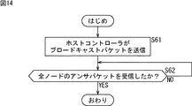
図14のフローチャートを参照して、図9のホストコントローラ231が、すべてのノードN1乃至Nnから情報を取得するときの処理について説明する。
A process when the
まず最初に、ステップS61において、ホストコントローラ231の制御部261は、制御機構部205からアクチュエータA1乃至Anのデータを取得する要求を受けた場合、リードリクエストパケットを作成し、通信部262へ供給する。さらに、ステップS61では、ホストコントローラ231の通信部262は、制御部261が作成したリードリクエストパケットを、メイン通信路241へ送信し、ステップS62に進む。即ち、制御部261は、コンテンツ無しのパケットのフォーマットを使用して、Type部にリードリクエスト信号を配置し、ADDR部にブロードキャスト信号を配置したパケットを作成し通信部262へ供給する。通信部262は、制御部261が供給したパケットを受取り、メイン通信路241を介して送信する。これにより、リードリクエストパケットがブロードキャストされる。
First, in step S <
ステップS62では、ホストコントローラ231の制御部261は、すべてのノードN1乃至Nnからアンサパケットを受信したか否かを判定する。ステップS62において、制御部261は、すべてのノードN1乃至Nnのアンサパケットを受信していないと判定した場合、ステップS62に戻り、同様の処理を繰り返す。一方、ステップS62において、制御部261は、すべてのノードN1乃至Nnからのアンサパケットを受信したと判定した場合、処理を終了する。これにより、ホストコントローラ231は、すべてのアクチュエータの状態を表すデータD1[0:m]乃至Dn[0:m]を取得する。
In step S62, the control unit 261 of the
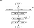
図15のフローチャートを参照して、ホストコントローラ231からブロードキャストによるリードリクエストパケットが送信されたときの、図9のノードNiの処理について説明する。
With reference to the flowchart of FIG. 15, when the read request packet by broadcast from the
まず最初に、ステップS71において、ノードNiの通信部271は、ホストコントローラ231が送信したリードリクエストパケットを受信する。通信部271は、受信したパケットのTypeおよびADDRを解析し、ADDRがブロードキャスト信号であり、Typeがリードリクエスト信号である場合、ホストコントローラ231が送信したブロードキャストによるリードリクエストパケットであると認識する。通信部271は、リードリクエストパケットを受信した旨の情報を解析部272へ供給し、解析部272は、供給されたリードリクエストパケットを受信した旨の情報に基づいて、ノードNiが制御するアクチュエータAiの状態を表すデータDi[0:m]を作成部273へ供給する。そして、ステップS71からステップS72に進む。
First, in step S71, the node N i communication unit 271 of the receives a read request packet to the
ステップS72において、作成部273は、解析部272から供給されたデータDi[0:m]をコンテンツ部に配置したアンサパケットを作成し、作成したアンサパケットを通信部271へ供給する。即ち、作成部273は、コンテンツ付のパケットのフォーマットを使用し、Type部にアンサ信号を配置し、ADDR部に自分を表す信号であるノード番号iを配置するとともに、ユーザデータ部にデータDi[0:m]を格納したパケットを作成する。
In step S <b> 72, the
ステップS72からS73に進み、通信部271は、ノードNi+1がアンサパケットを送信したか否かを判定する。即ち、通信部271は、メイン通信路241を介して送信される他のノードNjが送信したパケットを受信し、受信したパケットのType部にアンサ信号が配置されていない、もしくは、ADDR部にノード番号i+1が配置されていないと判定した場合、ステップS73に戻る。一方、通信部271は、受信したパケットのType部にアンサ信号が配置されており、且つ、ADDR部にノード番号i+1が配置されていると判定した場合、即ち、ノードNi+1がアンサパケットを送信したと認識した場合、次に自分のアンサパケットを送信する順番であると認識して、ステップS74に進む。
Proceeding from step S72 to S73, the
ステップS74において、通信部271は、ステップS73でノードNi+1のアンサパケットを受信したことを確認した後、自分のアンサパケットをホストコントローラ231へ送信し、処理を終了する。
In step S74, after confirming that the answer packet of node N i + 1 has been received in step S73, the
なお、ここでは、ノード番号が最大のノードNnが、ブロードキャストによるリードリクエストパケットに対するアンサパケットを最初に送信すべきノードであるが、この、アンサパケットを最初に送信すべきノードであるノードNnは、ステップS73の処理をスキップする。即ち、ノードNnは、ステップS72でアンサパケットを作成した後、ステップS74において、即座に、そのアンサパケットを送信する。 Here, the node N n having the largest node number is the node to which the answer packet for the broadcast read request packet is to be transmitted first, but this node N n is the node to which the answer packet is to be transmitted first. Skips the process of step S73. That is, after the node N n creates an answer packet in step S72, the answer packet is immediately transmitted in step S74.
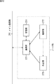
図16は、ホストコントローラ231と、ロボット5の各構成ユニット(胴体部ユニット11、頭部ユニット12、腕部ユニット13、脚部ユニット14)に配設されたノードN1乃至Nnとで構成される通信システムの第2の構成例を示している。
FIG. 16 includes a
図16において、ホストコントローラ231は、メイン通信路242を介して、ノードN1と接続している。そして、ノードN1は、メイン通信路242を介して、ノードN2とも接続している。以下、同様にして、最終的には、ノードNn-1は、メイン通信路242を介して、ノードNnと接続している。即ち、ホストコントローラ231とノードN1乃至Nnは、メイン通信路242を介して直列に接続されたデイジーチェーンの構造の通信システムを構成している。
In FIG. 16, the
さらに、図16のデイジーチェーンの構造の通信システムにおいて、ホストコントローラ231からノードNiの方向を下り方向と、ノードNiからホストコントローラ231の方向を上り方向と、それぞれいうものとすると、メイン通信路242は、上り方向と下り方向の両方向の通信路を有している。
Further, in the communication system of the structure of the daisy chain of FIG. 16, a downstream direction of node N i from the
ここで、図16のホストコントローラ231は、図11を参照して説明した通信部262と制御部261とで構成される。また、ホストコントローラ231とノードN1乃至Nnとで受け渡しをするパケットは、図13を参照して説明したパケットフォーマットのパケットである。
Here, the
図17は、図16のノードNiの機能的構成例を示すブロック図である。ノードNiは、通信部281、解析部272、作成部273、および記憶部274から構成されている。
Figure 17 is a block diagram illustrating a functional configuration example of a node N i in FIG. The node Ni includes a
ノードNiの通信部281は、下流側にあるメイン通信路242と上流側にあるメイン通信路242とを中継するようにして、メイン通信路242に接続している。従って、通信部281は、メイン通信路242を介して送信される、ホストコントローラ231が送信した下り方向のパケットを、上流側のメイン通信路242から受信する。また、通信部281は、メイン通信路242を介して送信される、下流側の他のノードNjが送信した上り方向のアンサパケットのすべてを、下流側のメイン通信路242から受信する。
The
また、通信部281は、受信した全てのパケットを同一方向へ転送する。また、通信部281は、受信したパケットのADDR部を解析する。通信部281は、受信したパケットが自分宛であると認識した場合、即ち、ADDR部に自分のノード番号iが格納されている場合、もしくは、ブロードキャスト信号が格納されている場合、受信したリードリクエストパケットを解析部272へ供給する。また、通信部281は、受信したリードリクエストパケットが他のノード宛である場合、即ち、ADDR部に他のノード番号jが格納されている場合、受信したリードリクエストパケットを無視(破棄)する。
Further, the
図17のノードNiの解析部272、作成部273、および記憶部274は、図12で示したバス型の通信システムにおけるノードNiの各部と同様の機能を有するので、説明は省略する。
図18は、ホストコントローラ231と、ロボット5の各構成ユニット(胴体部ユニット11、頭部ユニット12、腕部ユニット13、脚部ユニット14)に配設されたノードN1乃至Nnとで構成される通信システムの第3の構成例を示している。
FIG. 18 includes a
図18の通信システムにおいては、図16における場合と同様に、ホストコントローラ231とノードN1乃至Nnとが、メイン通信路243を介して直列に接続され、これにより、デイジーチェーン構造の通信システムが構成されている。但し、メイン通信路243を介した通信は、上り方向と下り方向の両方向について同時に行うことができず、いずれか一方向のみに行なうことが可能となっている。このため、ノードNiは、メイン通信路243の通信方向を切り替えながらパケットの送受信を行なう。
In the communication system of FIG. 18, as in the case of FIG. 16, the
即ち、ノードNiは、例えば、上流側からの下り方向のパケットを受信し、下流側にパケットを送信する状態となっている。例えば、ホストコントローラ231がブロードキャストによりリードリクエストパケットを送信した場合、このリードリクエストパケットは、下流側に転送(送信)される。また、ノードNiは、受信したリードリクエストパケットのADDR部を解析し、受信したリードリクエストパケットが下流側の他のノードNj宛(ブロードキャストリードリクエストを含む)である場合、メイン通信路243の通信方向を切り替え、下流側からの上り方向のパケットを受信し、上流側にパケットを送信する状態となる。さらに、ノードNiは、自分のアンサパケットを上流側へ送信した後、再び、メイン通信路243の通信方向を切り替え、上流側からの下り方向のパケットを受信する状態となる。
That is, for example, the node Ni is in a state of receiving a packet in the downstream direction from the upstream side and transmitting the packet to the downstream side. For example, when the
図19は、図18のノードNiの機能的構成例を示すブロック図である。ノードNiは、通信部291、通信部291に設置された通信切り替え部292、解析部272、作成部273、および記憶部274から構成されている。
Figure 19 is a block diagram illustrating a functional configuration example of a node N i of FIG. The node Ni includes a
ノードNiの通信部291は、下流側にあるメイン通信路243と上流側にあるメイン通信路243とを中継するようにして、メイン通信路243と接続している。従って、通信部291は、メイン通信路243を介して送信されるホストコントローラ231が送信した下り方向のリードリクエストパケットと、下流側の他のノードNjが送信した上り方向のアンサパケットとのすべてを受信する。
The
通信方向切り替え部292は、通信部291からメイン通信路243の通信方向を切り替える情報を受取ったとき、メイン通信路243の通信方向を、上り方向もしくは下り方向に切り替える。
When receiving the information for switching the communication direction of the
通信部291は、例えば、ホストコントローラ231がブロードキャストで送信した下り方向のリードリクエストパケットを受信した場合、受信したリードリクエストパケットを下流側へ転送する。さらに、通信部291は、その受信したリードリクエストパケットが自分より下流側の他のノードNj宛(ブロードキャストを含む)と認識した場合、通信方向切り替え部292によって、メイン通信路243の通信方向を下り方向から上り方向へ切り替えさせる。また、例えば、通信部291は、下流側の他のノードNi+1のアンサパケットを受信し上流側へ転送した後、自分のアンサパケットを上流側へ送信する。さらに、自分のアンサパケットを上流側へ送信した後、通信方向切り替え部292によって、メイン通信路243の通信方向を上り方向から下り方向へ切り替えさせる。
For example, when the
図19のノードNiの解析部272、作成部273、および記憶部274は、図12で示したバス型の通信システムにおけるノードNiの各部と同様の機能を有するのでその説明は省略する。
Node N i of the
このように、通信方向の切り替えが必要なメイン通信路243で接続されたデイジーチェーン構造の通信システムにおいても、ノードNiは、通信方向を切り替えながら、下流側のノードから順番に(ノード番号の降順で)アンサパケットを送信することができる。よって、ホストコントローラ231は、短時間ですべてのノードN1乃至Nnから情報を取得することができる。
As described above, even in a daisy chain communication system connected through the
なお、図9、図16、および図19に示した通信システムにおいて、ノードNiの記憶部274には、自分のノード番号iに加えて、自分が何番目にアンサパケットを送信するかの情報を記憶させておくことができる。この場合、ノードNiの通信部271、通信部281、並びに通信部291は、既に受信したアンサパケットの数をカウントすることにより、自身の送信する順番であることを認識することができる。ただし、図16及び図19の通信システムでは、ノードNiは、自分より下流側にあるノードが送信したアンサパケットしか受信できないので、即ち、自分より上流側にあるノードが送信したアンサパケットは受信することができないので、アンサパケットを送信する順番は、最も下流側にあるノードNnを1番目とし、ノード番号の降順とすることが望しい。
In the communication systems shown in FIG. 9, FIG. 16, and FIG. 19, the
また、図9および図16の通信システムにおいて、ノードNiの記憶部274には、他のノードNjのノード番号jを記憶させることができる。この場合、ノードNiの通信部271または通信部281は、受信したアンサパケットのノード番号が、記憶部274に記憶している他のノード番号jと一致したとき、次に自分のアンサパケットを送信する順番であることを認識することができる。
In the communication system of FIG. 9 and FIG. 16, the
さらに、図9、図16、および図19の通信システムにおいて、ノードNiの記憶部274には、所定の時間を記憶させておくことができる。この場合、ノードNiにおいて、あるトリガから所定の時間が経過したときに自身のアンサパケットを送信させることにより、すべてのノードN1乃至Nnが所定の順番にアンサパケットを送信することができる。即ち、例えば、ノードNiの通信部271、通信部281、並びに通信部291は、ブロードキャストによるリードリクエストパケットを受信したことをトリガに、所定の時間が経過したときに、自分のアンサパケットを送信することができる。但し、この場合、所定の時間は、ノードN1乃至Nnそれぞれが、ブロードキャストによるリードリクエストパケットを受信するタイミングのタイムラグを考慮して設定する必要がある。
Further, FIG. 9, in the communication system of FIG. 16, and 19, the
また、アンサパケットを最初に送信するノードNiは、記憶部274に、自身が最初に送信する旨を記憶しておくことができる。即ち、ノードNiは、その記憶部274に、自分のアンサパケットを一番に送信することを記憶している場合、ブロードキャストによるリードリクエストパケットを受信すると、即座にアンサパケットを送信する。
The node N i to send an answer packet for the first time, can be in the
さらに、ホストコントローラ231には、アンサパケットを送信する所定の順番を格納したパケットを送信させることができる。この場合、ノードNiは、ホストコントローラ231が送信した、アンサパケットを送信する所定の順番を格納したパケットを受信し、記憶部274に記憶している情報を更新することができる。
Further, the
図20は、ホストコントローラ231と、ロボット5の各構成ユニット(胴体部ユニット11、頭部ユニット12、腕部ユニット13、脚部ユニット14)に配設されたノードN1乃至Nnとで構成される通信システムの第4の構成例を示している。
FIG. 20 includes a
図20では、ホストコントローラ231とノードN1乃至Nnとは、メイン通信路241を介して接続しており、これにより、図9における場合と同様の通信システムを構成している。さらに、図20では、ノードNiと、ノードN1-1乃至N1-mとが、メイン通信路244を介して接続されている。
In FIG. 20, the
即ち、ノードN1は、メイン通信路241または他のノードN2乃至Nnからパケットを受信すると、そのパケットを、メイン通信路244を介して、ノードN1-1乃至N1-mに転送し、さらに、ノードN1は、ノードN1-1乃至N1-mからメイン通信路244を介して、パケットを受信すると、そのパケットを、メイン通信路241を介して、ホストコントローラ231と他のノードN2乃至Nnに転送する。これにより、ホストコントローラ231がブロードキャストにより送信したリードリクエストパケットに対して、ノードN1乃至Nnおよび、ノードN1-1乃至N1-mは、上述した場合と同様にして、アンサパケットを、所定の順番で送信する。
That is, when the node N 1 receives a packet from the main communication path 241 or the other nodes N 2 to N n , the node N 1 transfers the packet to the nodes N 1-1 to N 1-m via the
上述した一連の処理は、専用のハードウェアによっても、またソフトウェアによっても実行することができる。一連の処理をソフトウェアによって行なう場合には、そのソフトウェアを構成するプログラムが、通信システムを構成するハードウェアに組み込まれているコンピュータ、または、各種のプログラムをインストールすることで、各種の機能を実行することが可能な、例えば汎用のパーソナルコンピュータなどに、記録媒体からインストールされる。 The series of processes described above can be executed by dedicated hardware or software. When a series of processing is performed by software, a program constituting the software executes various functions by installing a computer incorporated in hardware constituting the communication system or various programs. For example, it is installed from a recording medium in a general-purpose personal computer or the like.
この記録媒体は、コンピュータとは別に、ユーザにプログラムを提供するために配布される、磁気ディスク(フレキシブルディスクを含む)、光ディスク(CD-ROM(Compact Disk-Read Only Memory),DVD(Digital Versatile Disk)を含む)、光磁気ディスク(MD(Mini-Disk)(商標)を含む)、もしくは半導体メモリなどよりなるパッケージメディアとして提供することができる。例えば、図7においては、プログラムは、外部メモリ106に記録して提供し、メモリ112にインストールすることができる。
This recording medium is distributed to provide a program to the user separately from the computer, such as a magnetic disk (including a flexible disk), an optical disk (CD-ROM (Compact Disk-Read Only Memory), DVD (Digital Versatile Disk). )), A magneto-optical disk (including MD (Mini-Disk) (trademark)), or a package medium made of a semiconductor memory or the like. For example, in FIG. 7, the program can be provided by being recorded in the
また、本明細書において、フローチャートに記述したステップは、記載された順序に沿って時系列的に行われる処理はもちろん、必ずしも時系列的に処理されなくとも、並列的あるいは個別に実行される処理をも含むものである。 In addition, in the present specification, the steps described in the flowchart are not only processes performed in time series in the order described, but also processes executed in parallel or individually even if not necessarily performed in time series. Is also included.
なお、本明細書において、システムとは、複数の装置により構成される装置全体を表すものである。 In the present specification, the term “system” represents the entire apparatus constituted by a plurality of apparatuses.
また、本実施の形態では、本発明をロボットに適用した場合について説明したが、本発明は、ロボット以外の1対多の通信を行なうシステムに適用可能である。 In this embodiment, the case where the present invention is applied to a robot has been described. However, the present invention can be applied to a system that performs one-to-many communication other than a robot.
5 ロボット, 11 胴体ユニット, 12 頭部ユニット, 13 腕部ユニット, 14 脚部ユニット, 52 制御ユニット, 61 メイン制御部, 106 外部メモリ, 112 メモリ, 205 制御機構部, 231 ホストコントローラ, 241 メイン通信路, 242 メイン通信路, 243 メイン通信路, 244 メイン通信路, 261 通信部, 262 制御部, 271 通信部, 272 解析部, 273 作成部, 274 記憶部, 281 通信部, 291 通信部, 292 通信方向切り替え部, A1乃至An アクチュエータ, N1乃至Nn ノード 5 robot, 11 body unit, 12 head unit, 13 arm unit, 14 leg unit, 52 control unit, 61 main control unit, 106 external memory, 112 memory, 205 control mechanism unit, 231 host controller, 241 main communication Path, 242 main communication path, 243 main communication path, 244 main communication path, 261 communication section, 262 control section, 271 communication section, 272 analysis section, 273 creation section, 274 storage section, 281 communication section, 291 communication section, 292 Communication direction switching unit, A 1 to An actuator, N 1 to N n nodes
Claims (11)
前記ホストコントローラは、前記ノードに対して情報を要求するパケットであるリードリクエストパケットをブロードキャストするブロードキャスト手段を備え、
前記複数のノードそれぞれは、
前記リードリクエストパケットを受信する受信手段と、
前記リードリクエストパケットに応答するアンサパケットを作成する作成手段と、
前記作成手段が作成したアンサパケットを所定の順番で送信する送信手段と
を備える
ことを特徴とする通信システム。 In a communication system in which a host controller and a plurality of nodes perform communication using packets,
The host controller includes broadcast means for broadcasting a read request packet that is a packet for requesting information to the node.
Each of the plurality of nodes
Receiving means for receiving the read request packet;
Creating means for creating an answer packet in response to the read request packet;
A communication system comprising: transmission means for transmitting the answer packets created by the creation means in a predetermined order.
前記ホストコントローラによってブロードキャストされる、情報を要求するパケットであるリードリクエストパケットを受信する受信手段と、
前記リードリクエストパケットに応答するアンサパケットを作成する作成手段と、
前記作成手段が作成したアンサパケットを所定の順番で送信する送信手段と
を備える
ことを特徴とする通信装置。 In one communication device among a plurality of communication devices that perform packet communication with the host controller,
Receiving means for receiving a read request packet, which is a packet requesting information, broadcast by the host controller;
Creating means for creating an answer packet in response to the read request packet;
A communication apparatus comprising: a transmission unit configured to transmit the answer packets generated by the generation unit in a predetermined order.
前記送信手段は、前記アンサパケットを、前記記憶手段に記憶された順番で送信する
ことを特徴とする請求項2に記載の通信装置。 Storage means for storing the order in which the answer packets are transmitted;
The communication device according to claim 2, wherein the transmission unit transmits the answer packets in the order stored in the storage unit.
前記送信手段は、自身のアンサパケットを送信すべき順番の1つ前に送信されるべき順番のアンサパケットが前記受信手段において受信された後、前記自身のアンサパケットを送信する
ことを特徴とする請求項2に記載の通信装置。 The receiving means further receives an answer packet transmitted by another communication device,
The transmission means transmits the answer packet after the answer packet in the order to be transmitted one order before the order in which the answer packet is to be transmitted is received by the reception means. The communication apparatus according to claim 2.
前記送信手段は、前記ホストコントローラに対して、自身の直後に接続されている他の通信装置がアンサパケットを送信した後、自身のアンサパケットを送信する
ことを特徴とする請求項2に記載の通信装置。 The plurality of communication devices are connected in series to the host controller,
3. The transmission unit according to claim 2, wherein the transmission unit transmits the answer packet to the host controller after another communication apparatus connected immediately after the transmitter transmits the answer packet. 4. Communication device.
前記ホストコントローラから前記複数の通信装置への方向を下り方向とするとともに、前記複数の通信装置から前記ホストコントローラの方向を上り方向として、
前記受信手段は、前記下り方向のパケットを受信した後、前記上り方向のパケットを受信する状態に切り替わり、
前記送信手段は、前記下り方向にパケットを送信した後、前記上り方向にパケットを送信する状態に切り替わる
ことを特徴とする請求項2に記載の通信装置。 The plurality of communication devices are connected in series to the host controller,
The direction from the host controller to the plurality of communication devices is a down direction, and the direction from the plurality of communication devices to the host controller is an up direction,
The receiving means switches to a state of receiving the uplink packet after receiving the downlink packet,
The communication apparatus according to claim 2, wherein the transmission unit switches to a state in which the packet is transmitted in the uplink direction after transmitting the packet in the downlink direction.
前記ホストコントローラから前記複数の通信装置への方向を下り方向とするとともに、前記複数の通信装置から前記ホストコントローラの方向を上り方向として、
前記受信手段は、前記上り方向と下り方向のパケットを受信し、
前記送信手段は、前記上り方向と下り方向にパケットを送信する
ことを特徴とする請求項2に記載の通信装置。 The plurality of communication devices are connected in series to the host controller,
The direction from the host controller to the plurality of communication devices is a down direction, and the direction from the plurality of communication devices to the host controller is an up direction,
The receiving means receives the upstream and downstream packets,
The communication apparatus according to claim 2, wherein the transmission unit transmits a packet in the uplink direction and the downlink direction.
ことを特徴とする請求項2に記載の通信装置。 The communication apparatus according to claim 2, wherein the host controller and the plurality of communication apparatuses are connected in series via a single communication path.
前記ホストコントローラによってブロードキャストされる、情報を要求するパケットであるリードリクエストパケットを受信する受信ステップと、
前記リードリクエストパケットに応答するアンサパケットを作成する作成ステップと、
前記作成ステップが作成したアンサパケットを所定の順番で送信する送信ステップと
を含む
ことを特徴とする通信方法。 A communication method in one communication device among a plurality of communication devices that perform packet communication with a host controller,
Receiving a read request packet, which is a packet requesting information, broadcast by the host controller;
Creating an answer packet in response to the read request packet;
And a transmission step of transmitting the answer packets created by the creation step in a predetermined order.
前記ホストコントローラによってブロードキャストされる、情報を要求するパケットであるリードリクエストパケットを受信させる受信ステップと、
前記リードリクエストパケットに応答するアンサパケットを作成させる作成ステップと、
前記作成ステップが作成したアンサパケットを所定の順番で送信させる送信ステップと
を含む
ことを特徴とするプログラム。 A program that causes a computer to perform communication processing of one communication device among a plurality of communication devices that perform communication with a host controller using packets,
A receiving step of receiving a read request packet, which is a packet requesting information, broadcast by the host controller;
Creating step for creating an answer packet in response to the read request packet;
And a transmission step for transmitting the answer packets created in the creation step in a predetermined order.
前記ホストコントローラによってブロードキャストされる、情報を要求するパケットであるリードリクエストパケットを受信させる受信ステップと、
前記リードリクエストパケットに応答するアンサパケットを作成させる作成ステップと、
前記作成ステップが作成したアンサパケットを所定の順番で送信させる送信ステップと
を含む
ことを特徴とするプログラムが記録されているプログラム記録媒体。 A program recording medium on which a program for causing a computer to perform communication processing of one of a plurality of communication devices that perform communication with a host controller by a packet is recorded,
A receiving step of receiving a read request packet, which is a packet requesting information, broadcast by the host controller;
Creating step for creating an answer packet in response to the read request packet;
A program recording medium on which a program is recorded, comprising: a transmission step of transmitting the answer packets created by the creation step in a predetermined order.
Priority Applications (1)
| Application Number | Priority Date | Filing Date | Title |
|---|---|---|---|
| JP2003354206A JP2005123744A (en) | 2003-10-14 | 2003-10-14 | COMMUNICATION SYSTEM, COMMUNICATION DEVICE, COMMUNICATION METHOD, PROGRAM, AND PROGRAM RECORDING MEDIUM |
Applications Claiming Priority (1)
| Application Number | Priority Date | Filing Date | Title |
|---|---|---|---|
| JP2003354206A JP2005123744A (en) | 2003-10-14 | 2003-10-14 | COMMUNICATION SYSTEM, COMMUNICATION DEVICE, COMMUNICATION METHOD, PROGRAM, AND PROGRAM RECORDING MEDIUM |
Publications (1)
| Publication Number | Publication Date |
|---|---|
| JP2005123744A true JP2005123744A (en) | 2005-05-12 |
Family
ID=34612249
Family Applications (1)
| Application Number | Title | Priority Date | Filing Date |
|---|---|---|---|
| JP2003354206A Withdrawn JP2005123744A (en) | 2003-10-14 | 2003-10-14 | COMMUNICATION SYSTEM, COMMUNICATION DEVICE, COMMUNICATION METHOD, PROGRAM, AND PROGRAM RECORDING MEDIUM |
Country Status (1)
| Country | Link |
|---|---|
| JP (1) | JP2005123744A (en) |
Cited By (3)
| Publication number | Priority date | Publication date | Assignee | Title |
|---|---|---|---|---|
| JP2011050176A (en) * | 2009-08-27 | 2011-03-10 | Yazaki Corp | Condition monitoring unit of plural assembled batteries |
| JP2015114810A (en) * | 2013-12-11 | 2015-06-22 | セイコーエプソン株式会社 | Detector, sensor, electronic apparatus, and mobile body |
| JP2016045138A (en) * | 2014-08-25 | 2016-04-04 | セイコーエプソン株式会社 | Sensor device, support substrate assembly, electronic equipment, and mobile body |
-
2003
- 2003-10-14 JP JP2003354206A patent/JP2005123744A/en not_active Withdrawn
Cited By (4)
| Publication number | Priority date | Publication date | Assignee | Title |
|---|---|---|---|---|
| JP2011050176A (en) * | 2009-08-27 | 2011-03-10 | Yazaki Corp | Condition monitoring unit of plural assembled batteries |
| US8552729B2 (en) | 2009-08-27 | 2013-10-08 | Yazaki Corporation | State monitoring unit for assembled battery |
| JP2015114810A (en) * | 2013-12-11 | 2015-06-22 | セイコーエプソン株式会社 | Detector, sensor, electronic apparatus, and mobile body |
| JP2016045138A (en) * | 2014-08-25 | 2016-04-04 | セイコーエプソン株式会社 | Sensor device, support substrate assembly, electronic equipment, and mobile body |
Similar Documents
| Publication | Publication Date | Title |
|---|---|---|
| US12267175B2 (en) | Transmission processing method and device | |
| EP1609568B1 (en) | Robot device, information processing method, and program | |
| CN111435901B (en) | Hybrid automatic repeat request acknowledgment feedback method, terminal and network equipment | |
| US20010021882A1 (en) | Robot apparatus and control method thereof | |
| CN110943816B (en) | A resource configuration method, terminal and network device | |
| JPWO1999067067A1 (en) | Robot device and information processing system | |
| CN110166206A (en) | A kind of the determination method and terminal of HARQ-ACK code book | |
| CN113660700A (en) | Information sending method, resource processing method, device and electronic equipment | |
| US20230355138A1 (en) | Electronic device and system for assisting user motion | |
| US12273188B2 (en) | Electronic device for transmitting and receiving data packet and operating method thereof | |
| KR20230043671A (en) | Electronic device for transmitting and receiving data packet and method for operation thereof | |
| US11916987B2 (en) | Electronic device for processing audio data, and operation method thereof | |
| CN110034893A (en) | A kind of UCI sending method and mobile terminal | |
| CN111355494A (en) | Check code processing method and device and electronic equipment | |
| JP2005123744A (en) | COMMUNICATION SYSTEM, COMMUNICATION DEVICE, COMMUNICATION METHOD, PROGRAM, AND PROGRAM RECORDING MEDIUM | |
| JP2002307350A (en) | Robot apparatus, operation control method of robot apparatus, control system of robot apparatus, program, and recording medium | |
| US20200164519A1 (en) | Motion control apparatus of action robot and motion generation and control system including the same | |
| CN114339707B (en) | Wireless earphone device, smart device, wireless communication system and communication method | |
| CN101346976A (en) | Method of sending a message, message transmitting device and message rendering device | |
| CN109120297A (en) | A kind of earphone far field exchange method, earphone far field interaction accessory and wireless headset | |
| JP2005202075A (en) | Dialog control system and method, and robot apparatus | |
| JP2004304714A (en) | Information processing system, information processing apparatus, information processing method, and program | |
| CN112653912A (en) | Electronic device and control method thereof | |
| JP2005123745A (en) | COMMUNICATION SYSTEM, COMMUNICATION DEVICE, COMMUNICATION METHOD, PROGRAM, AND PROGRAM RECORDING MEDIUM | |
| US20230413119A1 (en) | Multi-connection method and device based on target wake time |
Legal Events
| Date | Code | Title | Description |
|---|---|---|---|
| A300 | Application deemed to be withdrawn because no request for examination was validly filed |
Free format text: JAPANESE INTERMEDIATE CODE: A300 Effective date: 20070109 |