JP2005118466A - Controller for limb driving apparatus - Google Patents
Controller for limb driving apparatus Download PDFInfo
- Publication number
- JP2005118466A JP2005118466A JP2003359749A JP2003359749A JP2005118466A JP 2005118466 A JP2005118466 A JP 2005118466A JP 2003359749 A JP2003359749 A JP 2003359749A JP 2003359749 A JP2003359749 A JP 2003359749A JP 2005118466 A JP2005118466 A JP 2005118466A
- Authority
- JP
- Japan
- Prior art keywords
- coordinate system
- tangential
- output
- target
- unit
- Prior art date
- Legal status (The legal status is an assumption and is not a legal conclusion. Google has not performed a legal analysis and makes no representation as to the accuracy of the status listed.)
- Pending
Links
Images


Abstract
Description
本発明は、肢体駆動装置に関し、特に人間の関節やその他の治療対象への過負荷をなくし、装置の安全性を高めるよう肢体軌道を考慮した肢体駆動装置の制御装置に関する。 The present invention relates to a limb body driving device, and more particularly, to a control device for a limb body driving device in consideration of a limb body trajectory so as to eliminate overload on human joints and other treatment targets and improve the safety of the device.
従来、肢体を動かす装置には、医療分野で使用される連続他動運動装置(CPM装置)、リハビリテーション分野で使用される訓練装置やスポーツ・トレーニング装置等がある。このような装置において、人間の肢体位置を監視しながら動かし、関節に過負荷がかかる以前に対処でき、肢体の限界を考慮した稼働範囲を容易に設定でき、関節に負荷をかけず、装置自体にも安全性を持たせながら治療が行える肢体駆動装置の制御装置(例えば、特許文献1参照)があった。
以下、特許文献1について、図面を用いて簡単に説明する。
図12は制御装置の回路構成を示すブロック図である。図12において101は肢体駆動装置のアーム、102は肢体、103はアーム101の先端に取り付けられたスプリント(アーム先端位置)、104は力およびモーメントを検出する力センサ、105はアーム101を駆動するモータ、106はモータ105の回転角度を検出する回転角検出部、107は力センサ104の力およびモーメント信号をデジタル値に変換するA/D(アナログ/デジタル)変換器、108はA/D変換器の出力をアーム先端位置103の変位に変換する変位演算処理部、109はアーム先端位置103からモータ105の目標角度を算出する逆運動学計算部、110はアーム先端位置103の目標軌道を設定する目標軌道設定部、111は回転角検出部106の出力をデジタル値に変換する回転角変換回路、112はゲイン積分器、113はゲイン積分器112の出力をアナログ値に変換するD/A(デジタル/アナログ)変換器、114はD/A変換器113の出力に従って駆動モータ105を動かすサーボアンプ、115は肢体の動作負荷を推定計算する負荷推定部、116は関節負荷に応じて仮想バネ定数を変更するインピーダンス定数変換部である。
図12において、アーム101は3つのモータ105によって構成され、各モータは回転角検出部106を備えている。また、図12では簡単のために3つのモータのうち1つのみに回転角変換回路111およびサーボアンプ114が接続されているように描かれているが、実際はすべてのモータに回転角変換回路111およびサーボアンプ114が接続されている。
アーム101による肢体102への負荷が過負荷設定領域に入った時点で、アーム101が持つ全自由度のうち、ある自由度方向のインピーダンス定数変換部116を、肢体102への負荷が大きくなるに応じて変更し、その自由度方向の動作を仮想的にフリーにしていくことを特徴としている。
Conventionally, devices for moving a limb include a continuous passive motion device (CPM device) used in the medical field, a training device and a sports training device used in the rehabilitation field, and the like. In such a device, it can be moved while monitoring the position of the human limbs, can handle before the joint is overloaded, can easily set the operating range considering the limitations of the limbs, and does not put a load on the joint, the device itself In addition, there has been a control device for a limb body drive device (see, for example, Patent Document 1) that can perform treatment with safety.
Hereinafter,
FIG. 12 is a block diagram showing a circuit configuration of the control device. In FIG. 12, 101 is an arm of a limb body drive device, 102 is a limb body, 103 is a splint (arm tip position) attached to the tip of the
In FIG. 12, the
When the load on the
しかしながら、従来の肢体駆動装置の制御装置は、肢体への過負荷が発生した任意の自由度方向をフリーにするため、患者の関節の拘縮、痙性、筋緊張などによっても、任意の自由度方向へアームが動作することになり、そのため肢体の姿勢が崩れ、所望の治療姿勢とは異なる姿勢となるため、その時点で治療を停止しなければならないといった問題があった。
本発明はこのような問題点に鑑みてなされたものであり、患者の関節の拘縮、痙性、筋緊張などによって過負荷が発生した場合でも、肢体の姿勢が崩れることなく患者への過負荷を回避し、さらに治療継続が可能な肢体駆動装置の制御装置を提供することを目的とする。
However, the control device of the conventional limb body driving device frees the direction of the arbitrary degree of freedom in which the overload to the limb body has occurred. As the arm moves in the direction, the posture of the limbs collapses, resulting in a posture different from the desired treatment posture, and there is a problem that the treatment must be stopped at that time.
The present invention has been made in view of such a problem, and even when an overload occurs due to contracture, spasticity, muscle tone, etc. of the patient's joint, the patient is overloaded without the posture of the limbs collapsing. It is an object of the present invention to provide a control device for a limb body drive device that can avoid the above-described problem and can continue treatment.
上記問題を解決するため、本発明は、次のように構成したのである。
請求項1に記載の発明は、肢体に装着して前記肢体を動かす駆動部を備え、前記駆動部に取り付けられた位置・角度センサのセンシング情報をもとに、力制御または位置制御によって前記駆動部の動作を制御する肢体駆動装置の制御装置において、前記駆動部の先端が予め設定された軌道に沿って動作するように、動作指令を生成する目標軌道設定部と、前記目標軌道設定部の出力から前記軌道の接線方向を算出し接線座標系を導出する接線座標系生成手段と、前記接線座標系をもとに、前記軌道の接線方向には柔らかく、法線方向には硬くなるように力制御の制御座標系を制御する力方向制御手段と、前記位置・角度センサのセンシング情報と前記目標軌道設定部の出力と前記力方向制御手段の出力とに基づいて治療状態を提示する治療状態提示手段とを備えたことを特徴とするものである。
また、請求項2に記載の発明は、前記力方向制御手段は、前記軌道の接線方向の制限力と法線方向の制限力と、前記軌道の接線方向と法線方向にそれぞれ垂直な方向の制限力を各要素にもつ制限力ベクトルと、前記接線座標系と、前記肢体駆動装置の基準座標系と、から座標変換行列を算出し、前記制限力ベクトルと前記座標変換行列とヤコビ行列との積から前記駆動部の制限トルクを算出し、トルクを制限することを特徴とするものである。
また、請求項3に記載の発明は、前記接線座標系生成手段は、前記目標軌道設定部の出力と前記駆動部の位置情報とから、現在位置に最も近い前記目標軌道設定部の出力(目標点)を選択し、前記目標点を基に前記軌道の接線方向を算出し接線座標系を導出することを特徴とするものである。
また、請求項4に記載の発明は、前記接線座標系生成手段は、前記目標軌道設定部の出力と前記駆動部の位置情報とから、現在位置に最も近い前記目標軌道設定部の出力(目標点)を選択し、その間の距離が予め定めた規定値以上の場合は、警告情報を前記治療状態提示手段に出力することを特徴とするものである。
また、請求項5に記載の発明は、前記治療状態提示手段は、複数サイクルの治療状態を同時に提示することを特徴とするものである。
また、請求項6に記載の発明は、前記目標軌道設定部は、目標点と現在位置との間の距離が予め定めた閾値よりも大きい場合は、前記駆動部先端の動作方向が前記目標点と逆方向になるように動作指令を生成することを特徴とするものである。
また、請求項7に記載の発明は、前記目標軌道設定部は、目標点と現在位置との間の距離の時間変化が予め定めた閾値よりも大きい場合は、動作指令を停止することを特徴とするものである。
In order to solve the above problem, the present invention is configured as follows.
The invention according to
Further, in the invention according to
According to a third aspect of the present invention, the tangential coordinate system generating means outputs the output of the target trajectory setting unit closest to the current position (target target) from the output of the target trajectory setting unit and the position information of the drive unit. Point) is selected, the tangential direction of the trajectory is calculated based on the target point, and a tangential coordinate system is derived.
According to a fourth aspect of the present invention, the tangential coordinate system generating means outputs the output of the target trajectory setting unit closest to the current position (target target) from the output of the target trajectory setting unit and the position information of the drive unit. Point) is selected, and when the distance between them is equal to or greater than a predetermined value, warning information is output to the treatment state presenting means.
Further, the invention according to
Further, in the invention according to claim 6, when the distance between the target point and the current position is larger than a predetermined threshold, the target trajectory setting unit determines that the operation direction of the tip of the driving unit is the target point. The operation command is generated so as to be in the opposite direction.
Further, the invention according to claim 7 is characterized in that the target trajectory setting unit stops the operation command when the time change of the distance between the target point and the current position is larger than a predetermined threshold value. It is what.
請求項1記載の肢体駆動装置の制御装置によれば、患者の関節の拘縮、痙性、筋緊張などによって過負荷が発生した場合でも、予め設定された軌道上でフリーとなるため肢体の姿勢が崩れることなく患者への過負荷を回避し、さらに治療継続が可能である。
請求項2記載の肢体駆動装置の制御装置によれば、力センサ情報が無い場合においても、患者の関節の拘縮、痙性、筋緊張などによって過負荷が発生した場合に、予め設定された軌道上でフリーとなるため肢体の姿勢が崩れることなく患者への過負荷を回避し、さらに治療継続が可能である。
請求項3記載の肢体駆動装置の制御装置によれば、過負荷発生時にフィードバック位置が、その時点の目標点からずれた場合においても、その時点に応じた適切な目標点を選択し接線座標系を導出することが可能となり、適切な力方向の制御が可能となる。
請求項4記載の肢体駆動装置の制御装置によれば、患者の関節の拘縮、痙性、筋緊張などによる力以外の予想外の負荷が発生した場合、前記警告情報に基づいて速やかに装置を停止させることが可能で、装置の安全性を向上させる。
請求項5記載の肢体駆動装置の制御装置によれば、規則性のある過負荷状態を、作業療法士が容易に認識することが可能であり、より適切な治療方法の選定が可能である。
請求項6記載の肢体駆動装置の制御装置によれば、患者への過負荷が発生することなく、所望の軌道上で動作方向が反転するため連続して治療の継続が可能となり、治療効率の向上を実現できる。
請求項7記載の肢体駆動装置の制御装置によれば、通常の治療継続可能な拘縮、痙性、筋緊張などと異なる突発的な事態が発生した場合に、安全かつ速やかに装置の停止が可能となる。
According to the control device for a limb body driving device according to
According to the control device for a limb body driving device according to
According to the control device for the limb body driving device according to
According to the control device for a limb body driving device according to
According to the control device for the limb body driving device of the fifth aspect, the occupational therapist can easily recognize the regular overload state, and a more appropriate treatment method can be selected.
According to the control device of the limb body driving device according to claim 6, since the operation direction is reversed on a desired trajectory without causing overload to the patient, the treatment can be continuously continued, and the treatment efficiency is improved. Improvements can be realized.
According to the control device for the limb body driving device according to claim 7, the device can be safely and promptly stopped when a sudden situation occurs that is different from contracture, spasticity, muscle tension, etc. that can continue normal treatment. It becomes.
以下、この発明の実施の形態について図に基づいて説明する。 Hereinafter, embodiments of the present invention will be described with reference to the drawings.
図1において、図12と同じ符号のものは同一のものを指すので説明は省略する。1は目標軌道設定部110の出力と回転角変換回路112の出力とから軌道の接線方向を算出し接線座標系を導出する接線座標系生成手段、2は前記接線座標系をもとに、軌道の接線方向には柔らかく、法線方向には硬くなるように力制御の制御座標系を制御する力方向制御手段、3は前記力方向制御手段の出力に応じてゲイン積分器112の出力トルクを制限するトルク制限器、4は駆動モータ105の回転角度から前記駆動装置アーム101の重力トルクと摩擦トルクを計算し補償する重力・摩擦トルク補償器、5は前記目標軌道設定部110の出力と前記力方向制御手段2の出力と位置・角度センサのセンシング情報に基づく治療状態を提示する治療状態提示手段である。
なお、図12と同様に図1において、アーム101は3つのモータ105によって構成され、各モータは回転角検出部106を備えている。また、図1では簡単のために3つのモータのうち1つのみに回転角変換回路111およびサーボアンプ114が接続されているように描かれているが、実際はすべてのモータに回転角変換回路111およびサーボアンプ114が接続されている。
In FIG. 1, the same reference numerals as those in FIG.
As in FIG. 12, in FIG. 1, the
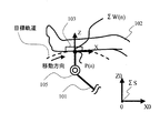
次に、動作形態について説明する。まず、患者の関節の拘縮、痙性、筋緊張が発生していない状態での動作形態(通常形態)について説明する。図2に肢体を運動させるために設定した目標軌道に従って装置が動作する際の、時刻Tにおける前記アーム先端位置103と時刻T前後の目標軌道を示す。ΣSは基準座標系を表す。
ここでは説明を簡単にするため、紙面の平面内を動作する駆動装置を考える。図2において、制御周期をΔTとし、時刻T(=ΔT・n :nは0以上の整数)における目標軌道の接線方向をX軸とし目標軌道の法線方向をZ軸とした、肢体の姿勢を表す座標系ΣW(n)を接線座標系とする。
図3は時刻Tの前後における接線座標系を示す図である。時刻Tの1制御周期前における接線座標系はΣW(n-1)、時刻Tの1制御周期後における接線座標系はΣW(n+1)となる。図3においてΣSは図2と同様に基準座標系を表す。前記接線座標系生成手段1は、前回のアーム先端位置P(n-1)と今回のアーム先端位置P(n)とから前記接線座標系ΣW(n)のX軸方向の基底ベクトルexとZ軸方向の基底ベクトルez を以下の(式1)(式2)(式3)に基づいて算出し、基準座標系ΣSに基づく接線座標系の変換行列[ex ey ez]を生成する。
Next, the operation mode will be described. First, an operation form (normal form) in a state where the contracture, spasticity, and muscle tone of the patient's joint have not occurred will be described. FIG. 2 shows the
Here, in order to simplify the description, a driving device that operates in the plane of the paper surface is considered. In FIG. 2, the posture of the limb with ΔT as the control cycle, the tangential direction of the target trajectory at time T (= ΔT · n: n is an integer of 0 or more) as the X axis, and the normal direction of the target trajectory as the Z axis. A coordinate system ΣW (n) representing is a tangential coordinate system.
FIG. 3 is a diagram showing a tangential coordinate system before and after time T. In FIG. The tangential coordinate system before one control cycle at time T is ΣW (n−1), and the tangential coordinate system after one control cycle at time T is ΣW (n + 1). In FIG. 3, ΣS represents the reference coordinate system as in FIG. The tangential coordinate system generation means 1 calculates the base vectors ex and Z in the X-axis direction of the tangential coordinate system ΣW (n) from the previous arm tip position P (n−1) and the current arm tip position P (n). An axial basis vector ez is calculated based on the following (Expression 1), (Expression 2), and (Expression 3) to generate a transformation matrix [ex ey ez] of a tangential coordinate system based on the reference coordinate system ΣS.

(式1)において、P(n-1)XおよびP(n)Xはそれぞれアーム先端位置P(n-1)、P(n)の基準座標系ΣSに基づくX軸方向の座標位置を示し、P(n-1)ZおよびP(n)Zはそれぞれアーム先端位置P(n-1)、P(n)の基準座標系ΣSに基づくZ軸方向の座標位置を示す。 In (Formula 1), P (n-1) X and P (n) X indicate the coordinate positions in the X-axis direction based on the reference coordinate system ΣS of the arm tip positions P (n-1) and P (n), respectively. , P (n-1) Z and P (n) Z indicate the coordinate positions in the Z-axis direction based on the reference coordinate system ΣS of the arm tip positions P (n-1) and P (n), respectively.
ここで、接線座標系ΣW(n)上で制限力ベクトル[limFx limFy limFz]T のlimFx(接線方向)の制限力を小さく、limFz(法線方向)を大きく設定する(limFyの制限力も大きく設定する)。
前記力方向制御手段2は、図4に示す処理フローに従って、アーム101の各モータの制限トルクτlimを算出する。ステップ2で、前記接線座標系生成手段1で生成された基準座標系ΣSに基づく接線座標系の変換行列[ex ey ez]を読み込む。次にステップ3で、前記設定された制限力ベクトル[limFx limFy limFz]T を読み込む。次にステップ4で、各モータのトルクと基準座標系ΣSの微小変位の対応関係を表すヤコビ行列Jを用いて、各モータの制限トルクτlimを算出する。前記制限トルクτlimを前記トルク制限器3に出力すると、トルク制限器3と重力・摩擦トルク補償器4により発生トルクが制限されるため、各モータは制限トルクτlim以上の負荷に対しては柔軟に倣う。この場合、アーム先端位置103での制限力の方向が目標軌道の接線方向に柔軟になるように制御されているため、肢体の姿勢が崩れることはない。
Here, on the tangential coordinate system ΣW (n), the limiting force vector [limFx limFy limFz] The limFx (tangential direction) limiting force of T is set small and limFz (normal direction) is set large (the limiting force of limFy is also set large) To do).
The force direction control means 2 calculates the limit torque τlim of each motor of the
次に、請求項3と請求項4に関連した患者の関節の拘縮、痙性、筋緊張が発生し、指令位置(制御周期ΔT後の次回の目標位置を示す)とフィードバック位置との偏差が大きくなった場合の動作形態について説明する。図5(a)にフィードバック位置が指令位置より進んだ場合の軌道の模式図を示し、図5(b)にフィードバック位置が指令位置より遅れた場合の軌道の模式図を示す。前記接線座標系生成手段1は、図5(a)、(b)に示す、制限軌道1と制限軌道2が目標軌道を挟んで距離dで設定されている。制限軌道1と制限軌道2は、安全上許容される軌跡ズレの範囲を規定する軌道である。fp(1)・・・fp(n)は過去から現在(n・ΔT)までのフィードバック位置を示し、tp(n)、tp(n+1)・・・は現在から未来への目標位置を示す。まず、図5(a)はフィードバック位置が指令位置より進んだ場合を示し、図5(b)は指令位置より遅れた場合を示している。前記接線座標系生成手段1は、図6に示す処理手順に従って、基準座標系ΣSに基づく接線座標系の変換行列[ex ey ez]を生成する。ステップ2で、現在のフィードバック位置(fp(n))を、前記回転角変換回路111の出力から入力する。ステップ3で、現在の指令値と現在から過去のm個と未来のそれぞれm個の指令値を、目標軌道設定部110から入力する(mは0以上の整数)。ステップ4で、距離|fp(n)−tp(k)|(k=n-m・・・n+m)が最小となるtp(k)を選択する。ステップ5で、上記ステップ4で最小となる距離をRとした時、前記距離Rが、制限軌道1と制限軌道2の範囲内に有るかどうかチェックする。ステップ6で、制限軌道の範囲外の場合は、アラームを前記治療状態提示手段5に出力する。ステップ7で、制限軌道の範囲内の場合、tp(k)とtp(k+1)とから基準座標系ΣSに基づく接線座標系の変換行列[ex ey ez]を算出し前記力方向制御手段2に出力する。それ以後の動作形態は、通常形態と同様であるため説明は省略する。
Next, contracture, spasticity, and muscle tension of the patient related to
次に、請求項5に記載の動作形態について説明する。図7に、前記治療状態提示手段5に提示された、3サイクルの治療状態を示す。図7には、それぞれの動作サイクルの前記アーム先端位置103の基準座標系ΣSに基づくX方向とZ方向の位置の時系列データが同時に表示され、時刻t0において、毎回同様に患者の関節の拘縮によって、目標軌道に対する追従特性が悪くなっていることが容易に理解でき、追従特性の違いにより制限力の設定等を変更する基準に活用することが可能となる。
Next, an operation mode according to
次に、請求項6と請求項7に記載の動作形態について説明する。図8に前記アーム101に取り付けられたスプリント(アーム先端位置)103の動作軌跡を示す。P1が開始位置で、通常P1→P2→P3→P2→P1→P2→P3→P2→P1・・・と往復動作を繰り返す。図9に示すように、時刻t1(図8における位置P2に対応)において、目標位置とフィードバック位置との間の距離(以後ΔERRとする)が、予め設定された閾値Cr1より大きくなった場合、請求項6記載のように前記目標軌道設定部110は、目標位置をP3からP1に切り替え、以後の動作軌跡はP1→P2→P1→P2→P1・・・で継続して実行される。また、前記目標設定部110は、P1の次の目標点をP2とせず、P2とP3の間の点を治療の状況に応じて段階的に設定することも当然可能である。
一方、前記P2でのΔERRが、時刻t2において通常の時間変化より急激に変化した場合を図10に示す。この場合は、請求項7記載のように、図11に示すΔERRの時間変化(ΔERR/Δt)が予め設定された閾値Cr2より大きくなるため前記目標軌道設定部110は、動作指令を生成せず装置を停止する。
Next, operation modes according to claims 6 and 7 will be described. FIG. 8 shows an operation locus of the sprint (arm tip position) 103 attached to the
On the other hand, FIG. 10 shows a case where ΔERR at P2 changes more rapidly than normal time change at time t2. In this case, as described in claim 7, since the time change (ΔERR / Δt) of ΔERR shown in FIG. 11 is larger than a preset threshold Cr2, the target
患者への過負荷をなくし、装置の安全性を高めるよう肢体軌道を考慮した肢体駆動装置に適用できる。 The present invention can be applied to a limb body driving device that considers the limb trajectory so as to eliminate overload on the patient and improve the safety of the device.
1 接線座標系生成手段
2 力方向制御手段
3 トルク制限器
4 重力・摩擦補償器
5 治療状態提示手段
101 駆動装置のアーム
102 肢体
103 スプリント(アーム先端位置)
104 力センサ
105 モータ
106 回転検出部
107 A/D変換器
108 変位演算処理部
109 逆運動学計算部
110 目標軌道設定部
111 回転角変換回路
112 ゲイン積分器
113 D/A変換器
114 サーボアンプ
115 負荷推定部
116 インピーダンス定数変換部
DESCRIPTION OF
Claims (7)
前記駆動部の先端が予め設定された軌道に沿って動作するように、動作指令を生成する目標軌道設定部と、
前記目標軌道設定部の出力から前記軌道の接線方向を算出し接線座標系を導出する接線座標系生成手段と、
前記接線座標系をもとに、前記軌道の接線方向には柔らかく、法線方向には硬くなるように力制御の制御座標系を制御する力方向制御手段と、
前記位置・角度センサのセンシング情報と前記目標軌道設定部の出力と前記力方向制御手段の出力とに基づいて治療状態を提示する治療状態提示手段と
を備えたことを特徴とする肢体駆動装置の制御装置。 A limb body drive device comprising a drive unit that is mounted on a limb and moves the limb body, and controls the operation of the drive unit by force control or position control based on sensing information of a position / angle sensor attached to the drive unit In the control device of
A target trajectory setting unit that generates an operation command so that the tip of the driving unit operates along a preset trajectory;
A tangential coordinate system generating means for calculating a tangential direction of the trajectory from the output of the target trajectory setting unit and deriving a tangential coordinate system;
Based on the tangential coordinate system, force direction control means for controlling the control coordinate system of force control so as to be soft in the tangential direction of the trajectory and hard in the normal direction;
A limb body driving device comprising: a treatment state presentation unit that presents a treatment state based on sensing information of the position / angle sensor, an output of the target trajectory setting unit, and an output of the force direction control unit. Control device.
The limb body drive according to any one of claims 1 to 6, wherein the target trajectory setting unit stops the operation command when the time change in the distance between the target point and the current position is larger than a predetermined threshold value. Control device for the device.
Priority Applications (1)
| Application Number | Priority Date | Filing Date | Title |
|---|---|---|---|
| JP2003359749A JP2005118466A (en) | 2003-10-20 | 2003-10-20 | Controller for limb driving apparatus |
Applications Claiming Priority (1)
| Application Number | Priority Date | Filing Date | Title |
|---|---|---|---|
| JP2003359749A JP2005118466A (en) | 2003-10-20 | 2003-10-20 | Controller for limb driving apparatus |
Publications (2)
| Publication Number | Publication Date |
|---|---|
| JP2005118466A true JP2005118466A (en) | 2005-05-12 |
| JP2005118466A5 JP2005118466A5 (en) | 2006-10-26 |
Family
ID=34615872
Family Applications (1)
| Application Number | Title | Priority Date | Filing Date |
|---|---|---|---|
| JP2003359749A Pending JP2005118466A (en) | 2003-10-20 | 2003-10-20 | Controller for limb driving apparatus |
Country Status (1)
| Country | Link |
|---|---|
| JP (1) | JP2005118466A (en) |
Cited By (7)
| Publication number | Priority date | Publication date | Assignee | Title |
|---|---|---|---|---|
| WO2007029418A1 (en) * | 2005-09-02 | 2007-03-15 | Honda Motor Co., Ltd. | Motion guide device, and its control system and control program |
| JP2015144787A (en) * | 2014-02-04 | 2015-08-13 | 三菱重工業株式会社 | Load support equipment, control method of the load support equipment, and computer-readable recording medium that records program for executing the control method |
| JP2016083313A (en) * | 2014-10-29 | 2016-05-19 | 村田機械株式会社 | Training device |
| JP2016083309A (en) * | 2014-10-29 | 2016-05-19 | 村田機械株式会社 | Training device, calculation method, and program |
| JPWO2015072479A1 (en) * | 2013-11-14 | 2017-03-16 | 村田機械株式会社 | Training equipment |
| JPWO2015072480A1 (en) * | 2013-11-14 | 2017-03-16 | 村田機械株式会社 | Training equipment |
| CN116966057A (en) * | 2023-08-07 | 2023-10-31 | 同济大学浙江学院 | Joint function traction rehabilitation robot auxiliary training method and system |
-
2003
- 2003-10-20 JP JP2003359749A patent/JP2005118466A/en active Pending
Cited By (13)
| Publication number | Priority date | Publication date | Assignee | Title |
|---|---|---|---|---|
| WO2007029418A1 (en) * | 2005-09-02 | 2007-03-15 | Honda Motor Co., Ltd. | Motion guide device, and its control system and control program |
| KR100979663B1 (en) | 2005-09-02 | 2010-09-02 | 혼다 기켄 고교 가부시키가이샤 | Motion guide device, and its control system and control program |
| US7942833B2 (en) | 2005-09-02 | 2011-05-17 | Honda Motor Co., Ltd. | Motion guide device, and its control system and control program |
| US10058473B2 (en) | 2013-11-14 | 2018-08-28 | Murata Machinery, Ltd. | Training apparatus |
| JPWO2015072479A1 (en) * | 2013-11-14 | 2017-03-16 | 村田機械株式会社 | Training equipment |
| JPWO2015072480A1 (en) * | 2013-11-14 | 2017-03-16 | 村田機械株式会社 | Training equipment |
| US9833374B2 (en) | 2013-11-14 | 2017-12-05 | Murata Machinery, Ltd. | Training apparatus |
| JP2015144787A (en) * | 2014-02-04 | 2015-08-13 | 三菱重工業株式会社 | Load support equipment, control method of the load support equipment, and computer-readable recording medium that records program for executing the control method |
| JP2016083313A (en) * | 2014-10-29 | 2016-05-19 | 村田機械株式会社 | Training device |
| JP2016083309A (en) * | 2014-10-29 | 2016-05-19 | 村田機械株式会社 | Training device, calculation method, and program |
| US10555864B2 (en) | 2014-10-29 | 2020-02-11 | Murata Machinery, Ltd. | Training apparatus, calculating method, and program |
| CN116966057A (en) * | 2023-08-07 | 2023-10-31 | 同济大学浙江学院 | Joint function traction rehabilitation robot auxiliary training method and system |
| CN116966057B (en) * | 2023-08-07 | 2024-01-05 | 同济大学浙江学院 | Joint function traction rehabilitation robot auxiliary training method and system |
Similar Documents
| Publication | Publication Date | Title |
|---|---|---|
| US6987374B2 (en) | Robot apparatus, and load absorbing apparatus and method | |
| Kong et al. | A compact rotary series elastic actuator for knee joint assistive system | |
| US8614558B2 (en) | Motor control apparatus and motor control method thereof | |
| EP2818150B1 (en) | Rehabilitation device, control method, control program, and recording medium | |
| JP2010207986A (en) | Robot device and method of controlling the same | |
| US20050184697A1 (en) | Robot apparatus, and load absorbing apparatus and method | |
| JP5375522B2 (en) | Robot arm control device, control method thereof, and program | |
| JP2005118466A (en) | Controller for limb driving apparatus | |
| JP2004148466A (en) | Robot controller | |
| JP4639417B2 (en) | Robot control device | |
| JP3286842B2 (en) | Flexible control device for robot | |
| JP2015221073A (en) | Rehabilitation apparatus, control method and control program | |
| JP4842561B2 (en) | Force controller device | |
| JPH1177580A (en) | Robot controller | |
| JPH10180663A (en) | Controller for robot arm | |
| JP3638048B2 (en) | Control device for limb body drive device | |
| JP4524729B2 (en) | Remote control robot controller | |
| JP5660482B2 (en) | Control method and control device for feed drive system of machine tool | |
| JP3424849B2 (en) | Manipulator compliance controller | |
| JP2007105823A (en) | Device and method of flexible control for manipulator | |
| JP4513071B2 (en) | Robot control device | |
| JP2007136564A (en) | Manipulator control method and device | |
| JP2005088114A (en) | Direct teaching device of robot | |
| KR102228527B1 (en) | Method and apparatus for controlling wearable robot | |
| WO2023127652A1 (en) | Gripping device and method for controlling gripping device |
Legal Events
| Date | Code | Title | Description |
|---|---|---|---|
| A521 | Written amendment |
Free format text: JAPANESE INTERMEDIATE CODE: A523 Effective date: 20060908 |
|
| A621 | Written request for application examination |
Free format text: JAPANESE INTERMEDIATE CODE: A621 Effective date: 20060908 |
|
| A131 | Notification of reasons for refusal |
Free format text: JAPANESE INTERMEDIATE CODE: A131 Effective date: 20090224 |
|
| A02 | Decision of refusal |
Free format text: JAPANESE INTERMEDIATE CODE: A02 Effective date: 20090706 |