JP2005114866A - Recording material discrimination device and image forming device - Google Patents
Recording material discrimination device and image forming device Download PDFInfo
- Publication number
- JP2005114866A JP2005114866A JP2003346279A JP2003346279A JP2005114866A JP 2005114866 A JP2005114866 A JP 2005114866A JP 2003346279 A JP2003346279 A JP 2003346279A JP 2003346279 A JP2003346279 A JP 2003346279A JP 2005114866 A JP2005114866 A JP 2005114866A
- Authority
- JP
- Japan
- Prior art keywords
- recording material
- light
- image
- predetermined
- reflection type
- Prior art date
- Legal status (The legal status is an assumption and is not a legal conclusion. Google has not performed a legal analysis and makes no representation as to the accuracy of the status listed.)
- Pending
Links
Images


Abstract
Description
本発明は、記録材判別装置および画像形成装置に関し、より詳細には、記録材の表面からの反射光および記録材の透過光量を検出してその種類を判別する記録材判別装置および画像形成装置に関する。 The present invention relates to a recording material determination device and an image forming apparatus, and more specifically, a recording material determination device and an image forming apparatus for detecting the reflected light from the surface of the recording material and the transmitted light amount of the recording material to determine the type. About.
複写機、レーザープリンタ等の画像形成装置は、記録材に現像部により可視化・現像された像を転写して所定の定着処理条件において加熱及び加圧することにより上記現像剤像を定着させる。この所定の定着条件は、記録材の材質、厚さ、表面処理などによって大きく異なるため、複数種類の記録材を使用するためには、記録材の種類に応じたきめ細かな設定が必要である。 Image forming apparatuses such as copying machines and laser printers fix the developer image by transferring an image visualized and developed by a developing unit to a recording material and heating and pressing under predetermined fixing processing conditions. The predetermined fixing conditions vary greatly depending on the material, thickness, surface treatment, and the like of the recording material. Therefore, in order to use a plurality of types of recording materials, fine setting according to the type of the recording material is required.
従来、かかる画像形成装置においては、例えば、画像形成装置本体に設けられた操作パネル等に記録材のサイズや種類(記録材が紙の場合は紙種)をユーザに設定させ、その設定に応じて定着処理条件(例えば、定着温度や定着装置を通過する記録材の搬送速度)を変更していた。 Conventionally, in such an image forming apparatus, for example, the user can set the size and type of the recording material on the operation panel or the like provided in the main body of the image forming apparatus (the paper type when the recording material is paper), and the user can The fixing processing conditions (for example, the fixing temperature and the conveyance speed of the recording material passing through the fixing device) are changed.
このため、近年では画像形成装置内部に記録材を判別するセンサを用いて記録材の種類を自動的に判別し、判別された種類に対応して現像条件、転写条件あるいは定着条件を可変制御する技術が提案されている。 For this reason, in recent years, the type of recording material is automatically determined using a sensor for determining the recording material inside the image forming apparatus, and development conditions, transfer conditions, or fixing conditions are variably controlled corresponding to the determined types. Technology has been proposed.
このような自動的に記録材の種類を検出する技術には、例えば、記録材の表面画像をCCDセンサによって撮像し、この情報をフラクタル次元情報に変換して記録材の表面平滑度を検出する方式、記録材の表面画像をCCDセンサあるいはCMOSセンサによって撮像しその光の大小関係から記録材の粗度を検出し表面平滑度から紙種を判別する方法、または記録材端部に出来る影の長さから記録材の厚みを検出する方法が提案されている(例えば、特許文献1参照)。 In such a technique for automatically detecting the type of recording material, for example, a surface image of the recording material is captured by a CCD sensor, and this information is converted into fractal dimension information to detect the surface smoothness of the recording material. Method, a method of capturing the surface image of the recording material with a CCD sensor or CMOS sensor, detecting the roughness of the recording material from the magnitude relationship of the light, and discriminating the paper type from the surface smoothness, A method of detecting the thickness of the recording material from the length has been proposed (see, for example, Patent Document 1).
しかしながら、上記の記録材の表面平滑度を検出する方法は、表面平滑度が同様で紙繊維の圧縮状態が異なる記録材、例えば普通紙と厚紙を検出すると厚紙が普通紙と判定されてしまい、現像条件、定着条件、転写条件をその記録紙に適した設定にできないため、定着性が悪くなるといった課題がある。 However, the method for detecting the surface smoothness of the recording material described above is to detect the recording material having the same surface smoothness and different compression state of the paper fiber, for example, plain paper and cardboard, and the cardboard is determined to be plain paper. Since the development conditions, fixing conditions, and transfer conditions cannot be set to be suitable for the recording paper, there is a problem that the fixing property is deteriorated.
一方、上記の記録材の材厚を判定する方法では、記録材表面の平滑度が分からないため、グロス紙等は普通紙に比べ光を通しにくいことから材厚が厚めに判定されてしまい適切な条件の設定ができない。 On the other hand, in the above method for determining the thickness of the recording material, since the smoothness of the surface of the recording material is not known, gloss paper or the like is less likely to transmit light than plain paper, so the material thickness is determined to be thick and appropriate. I cannot set the correct conditions.
さらに、近年では記録材の種類が多様になっているにも拘らず、印字品質に対する要求はより高くなっており、多種多様な記録材を正確に判別することが要求されている。 Further, in recent years, despite the variety of types of recording materials, the demand for print quality is higher, and it is required to accurately discriminate a wide variety of recording materials.
本発明は、このような問題に鑑みて為されたものであり、様々な種類の記録材を自動判別するとともに、適切な条件において画像形成を行う記録材判別装置および画像形成装置を提供することを目的とする。 The present invention has been made in view of the above problems, and provides a recording material determination device and an image forming apparatus that automatically determine various types of recording materials and perform image formation under appropriate conditions. With the goal.
このような目的を達成するため、本発明の請求項1に記載の発明は、記録材に光を照射し記録材の表面から反射する反射光を読み取ることにより記録材表面の映像を得る映像読取手段を含み、映像読取手段によって得られた記録材表面の映像を用いて該記録材の所定の属性を判定する反射型判定手段を備え、反射型判定手段により得られた属性に基づいて記録材の種類を判別する記録材判別装置において、反射型判定手段において用いられる照射光よりも長い波長を有する所定の照射光を記録材に照射することにより、記録材を透過して得られる透過光を用いて、記録材の反射型判定手段とは異なる属性を判定する透過型判定手段を備え、反射型判定手段により得られた属性に加えて、透過型判定手段により得られた属性に基づいて記録材の種類を判別することを特徴とする。 In order to achieve such an object, the invention described in claim 1 of the present invention is an image reading method for obtaining an image on the surface of a recording material by irradiating the recording material with light and reading reflected light reflected from the surface of the recording material. And a reflection type determination means for determining a predetermined attribute of the recording material using an image on the surface of the recording material obtained by the image reading means, and the recording material based on the attribute obtained by the reflection type determination means In the recording material discriminating apparatus for discriminating the type of the recording material, the transmitted light obtained by passing through the recording material is irradiated by irradiating the recording material with predetermined irradiation light having a wavelength longer than the irradiation light used in the reflection type determination means. And a transmission type determination unit that determines an attribute different from the reflection type determination unit of the recording material, and records based on the attribute obtained by the transmission type determination unit in addition to the attribute obtained by the reflection type determination unit. Material And discriminates the kind.
請求項2に記載の発明は、記録材に光を照射し記録材の表面から反射する反射光を読み取ることにより記録材表面の映像を得る映像読取手段を含み、映像読取手段によって得られた記録材表面の映像を用いて記録材の所定の属性を判定する反射型判定手段を備え、反射型判定手段により得られた属性に基づいて記録材の種類を判別する記録材判別装置において、反射型判定手段において用いられる照射光よりも強い光量の所定の照射光を記録材に照射することにより、記録紙を透過して得られる透過光であって、所定の照射光の光量を調整することにより反射光の光量と透過光の光量との差が所定の範囲内となる透過光を用いて、記録材の反射型判定手段とは異なる属性を判定する透過型判定手段を備え、反射型判定手段により得られた属性に加えて、透過型判定手段により得られた属性に基づいて記録材の種類を判別することを特徴とする。 The invention described in claim 2 includes image reading means for obtaining an image on the surface of the recording material by irradiating the recording material with light and reading reflected light reflected from the surface of the recording material. In a recording material discriminating apparatus, comprising a reflection type judging means for judging a predetermined attribute of a recording material using an image of the material surface, and discriminating the type of the recording material based on the attribute obtained by the reflection type judging means, the reflection type By irradiating the recording material with a predetermined amount of irradiation light that is stronger than the irradiation light used in the determining means, the transmitted light is transmitted through the recording paper, and by adjusting the amount of the predetermined irradiation light A transmission type determination unit for determining an attribute different from the reflection type determination unit of the recording material using transmitted light in which a difference between the amount of reflected light and the amount of transmitted light is within a predetermined range; Attribute obtained by In addition, and discriminates the type of the recording material based on the attribute obtained by the transmission type determination means.
請求項4に記載の発明は、記録材の表面から反射する反射光を得るため記録材に所定の光を照射する反射型照射手段と、記録材からの反射光または透過光を受光して映像として読み取り、および光量を検出する読み取り手段と、反射型照射手段に記録材へ光を照射させ、読み取り手段に反射型照射手段により得られた反射光を映像として読み取らせ、映像に基づいて記録材の種類を判別する制御手段とを備えた記録材判別装置において、記録材を透過する透過光を得るため記録材に反射型照射手段で照射される所定の光よりも長い波長を有する所定の光を照射する透過型照射手段を備え、制御手段は、反射型照射手段と透過型照射手段とに記録材へ光を照射させ、読み取り手段に反射型照射手段により得られた反射光を映像として読み取らせ、および透過型照射手段により得られた透過光の光量を検出させて、映像と透過光の光量とに基づいて前記記録材の種類を判別することを特徴とする。 According to a fourth aspect of the present invention, there is provided a reflection type irradiating means for irradiating a recording material with a predetermined light to obtain reflected light reflected from the surface of the recording material, and an image obtained by receiving reflected light or transmitted light from the recording material. Reading means for detecting the amount of light and a reflection type irradiation means for irradiating the recording material with light, causing the reading means to read the reflected light obtained by the reflection type irradiation means as an image, and recording material based on the image In a recording material discriminating apparatus comprising a control means for discriminating the type of light, a predetermined light having a wavelength longer than the predetermined light irradiated to the recording material by the reflective irradiation means in order to obtain transmitted light that passes through the recording material The control means irradiates the recording material with light by the reflection type irradiation means and the transmission type irradiation means, and the reading means reads the reflected light obtained by the reflection type irradiation means as an image. Set And the quantity of the resulting transmitted light by transmission illumination means is detected, and wherein the determining the type of the recording medium based on the light intensity of the image with the transmitted light.
請求項5に記載の発明は、記録材の表面から反射する反射光を得るため記録材に所定の光を照射する反射型照射手段と、記録材からの反射光または透過光を受光して映像として読み取り、および光量を検出する読み取り手段と、反射型照射手段に記録材へ光を照射させ、読み取り手段に反射型照射手段により得られた反射光を映像として読み取らせ、映像に基づいて記録材の種類を判別する制御手段とを備えた記録材判別装置において、記録材を透過する透過光を得るため記録材に反射型照射手段で照射される所定の光よりも強い光量の所定の光であって、所定の光の光量を調整することにより反射光の光量と透過光の光量との差が所定の範囲内となる所定の光を照射する透過型照射手段を備え、制御手段は、反射型照射手段と透過型照射手段とに記録材へ光を照射させ、読み取り手段に反射型照射手段により得られた反射光を映像として読み取らせ、および透過型照射手段により得られた透過光の光量を検出させて、映像と透過光の光量とに基づいて前記記録材の種類を判別することを特徴とする。 According to a fifth aspect of the present invention, there is provided a reflection type irradiating means for irradiating a recording material with a predetermined light to obtain reflected light reflected from the surface of the recording material, and an image obtained by receiving reflected light or transmitted light from the recording material. Reading means for detecting the amount of light and a reflection type irradiation means for irradiating the recording material with light, causing the reading means to read the reflected light obtained by the reflection type irradiation means as an image, and recording material based on the image And a recording material discriminating apparatus having a control means for discriminating the type of the recording material in order to obtain transmitted light that passes through the recording material with a predetermined amount of light that is stronger than the predetermined light that is irradiated to the recording material by the reflection type irradiation means. And a transmission type irradiating means for irradiating the predetermined light so that the difference between the light quantity of the reflected light and the light quantity of the transmitted light is within a predetermined range by adjusting the light quantity of the predetermined light. Type irradiation means and transmission type irradiation hand And irradiates the recording material with light, causes the reading means to read the reflected light obtained by the reflection-type irradiation means as an image, and detects the amount of transmitted light obtained by the transmission-type irradiation means, thereby transmitting the image and transmission. The type of the recording material is determined based on the amount of light.
請求項7に記載の発明は、潜像を担持する潜像担持体と、潜像担持体に現像剤を付与することにより潜像を現像剤像として可視化する現像手段と、所定方向に搬送される記録材に現像手段による現像剤像を転写する転写手段と、転写手段によって現像剤像を転写された記録材を所定の定着処理条件において加熱および加圧することにより現像剤像を記録材に定着させる定着手段と、記録材に光を照射し記録材の表面から反射する反射光を読み取ることにより記録材表面の映像を得る映像読取手段を含み、映像読取手段によって得られた記録材表面の映像を用いて記録材の所定の属性を判定する反射型判定手段とを備え反射型判定手段により得られた属性に基づいて記録材の種類を判別し、判別された種類に対応する定着処理条件により現像剤像を記録材に定着させる画像形成装置において、記反射型判定手段において用いられる照射光よりも長い波長を有する所定の照射光を記録材に照射することにより、記録材を透過して得られる透過光を用いて、記録材の反射型判定手段とは異なる属性を判定する透過型判定手段を備え、定着手段は、反射型判定手段により得られた属性に加えて、透過型判定手段により得られた属性に基づいて記録材の種類を判別し、判別された種類に対応する定着処理条件により現像剤像を記録材に定着させることを特徴とする。 According to a seventh aspect of the present invention, there is provided a latent image carrier that carries a latent image, a developing unit that visualizes the latent image as a developer image by applying a developer to the latent image carrier, and is conveyed in a predetermined direction. The developer image is fixed to the recording material by transferring and transferring the developer image by the developing device to the recording material to be recorded, and the recording material to which the developer image has been transferred by the transferring device being heated and pressed under predetermined fixing processing conditions. An image of the surface of the recording material obtained by the image reading means, including a fixing means for causing the image to be obtained by irradiating the recording material with light and reading reflected light reflected from the surface of the recording material. And a reflection type determination unit that determines a predetermined attribute of the recording material using the recording medium. The type of the recording material is determined based on the attribute obtained by the reflection type determination unit, and the fixing processing condition corresponding to the determined type is used. Developer In the image forming apparatus for fixing the recording material to the recording material, the transmitted light obtained by transmitting the recording material by irradiating the recording material with a predetermined irradiation light having a wavelength longer than the irradiation light used in the reflection type determination means And a transmission type determination unit that determines an attribute different from the reflection type determination unit of the recording material, and the fixing unit is obtained by the transmission type determination unit in addition to the attribute obtained by the reflection type determination unit. The type of the recording material is determined based on the attribute, and the developer image is fixed on the recording material according to the fixing processing condition corresponding to the determined type.
請求項8に記載の発明は、潜像を担持する潜像担持体と、潜像担持体に現像剤を付与することにより潜像を現像剤像として可視化する現像手段と、所定方向に搬送される記録材に現像手段による現像剤像を転写する転写手段と、転写手段によって現像剤像を転写された記録材を所定の定着処理条件において加熱および加圧することにより現像剤像を記録材に定着させる定着手段と、記録材に光を照射し記録材の表面から反射する反射光を読み取ることにより記録材表面の映像を得る映像読取手段を含み、映像読取手段によって得られた記録材表面の映像を用いて記録材の所定の属性を判定する反射型判定手段とを備え反射型判定手段により得られた属性に基づいて記録材の種類を判別し、判別された種類に対応する定着処理条件により現像剤像を記録材に定着させる画像形成装置において、反射型判定手段において用いられる照射光よりも強い光量の所定の照射光を記録材に照射することにより、記録紙を透過して得られる透過光であって、所定の照射光の光量を調整することにより反射光の光量と透過光の光量との差が所定の範囲内となる透過光を用いて、記録材の反射型判定手段とは異なる属性を判定する透過型判定手段を備え、定着手段は、反射型判定手段により得られた属性に加えて、透過型判定手段により得られた属性に基づいて記録材の種類を判別し、判別された種類に対応する定着処理条件により現像剤像を記録材に定着させることを特徴とする。 According to an eighth aspect of the present invention, there is provided a latent image carrier that carries a latent image, a developing unit that visualizes the latent image as a developer image by applying a developer to the latent image carrier, and is conveyed in a predetermined direction. The developer image is fixed to the recording material by transferring and transferring the developer image by the developing device to the recording material to be recorded, and the recording material to which the developer image has been transferred by the transferring device being heated and pressed under predetermined fixing processing conditions. An image of the surface of the recording material obtained by the image reading means, including a fixing means for causing the image to be obtained by irradiating the recording material with light and reading reflected light reflected from the surface of the recording material. And a reflection type determination unit that determines a predetermined attribute of the recording material using the recording medium. The type of the recording material is determined based on the attribute obtained by the reflection type determination unit, and the fixing processing condition corresponding to the determined type is used. Developer In the image forming apparatus for fixing the recording material to the recording material, it is transmitted light obtained by transmitting the recording material by irradiating the recording material with predetermined irradiation light having a light intensity stronger than the irradiation light used in the reflection type determination unit. Thus, by adjusting the light quantity of the predetermined irradiation light and using the transmitted light in which the difference between the light quantity of the reflected light and the light quantity of the transmitted light is within a predetermined range, an attribute different from that of the reflection type determination unit of the recording material is set. A transmissive type determining unit for determining, and the fixing unit determines the type of the recording material based on the attribute obtained by the transmissive type determining unit in addition to the attribute obtained by the reflective type determining unit. The developer image is fixed on the recording material according to fixing processing conditions corresponding to the above.
請求項10に記載の発明は、潜像を担持する潜像担持体と、潜像担持体に現像剤を付与する現像手段と、記録材に現像剤像を転写する転写手段と、加熱および加圧することにより現像剤像を記録材に定着させる定着手段と、記録材の表面から反射する反射光を得るため記録材に所定の光を照射する反射型照射手段と、現像手段で潜像を現像剤像として可視化させ、転写手段で所定方向に搬送させた記録材に可視化された像を転写させ、記録材からの反射光または透過光を受光して映像として読み取り、および光量を検出する読み取り手段と、反射型照射手段に記録材へ光を照射させ、読み取り手段に反射型照射手段により得られた反射光を映像として読み取らせ、映像に基づいて記録材の種類を判別し、判別された種類に対応する所定の定着処理条件において定着手段で転写された記録材を定着させ、定着された記録材を排出する制御手段を備えた画像形成装置において、記録材を透過する透過光を得るため記録材に反射型照射手段で照射される所定の光よりも長い波長を有する所定の光を照射する透過型照射手段を備え、制御手段は、転写手段で転写させる前に、反射型照射手段と透過型照射手段とに記録材へ光を照射させ、読み取り手段に反射型照射手段により得られた反射光を映像として読み取らせ、および透過型照射手段により得られた透過光の光量を検出させて、映像と該透過光の光量とに基づいて記録材の種類を判別し、判別された種類に対応する定着処理条件により現像剤像を記録材に定着させることを特徴とする。 According to a tenth aspect of the present invention, there is provided a latent image carrier that carries a latent image, a developing unit that applies a developer to the latent image carrier, a transfer unit that transfers a developer image to a recording material, and heating and heating. The latent image is developed by a fixing unit that fixes the developer image onto the recording material by pressing, a reflective irradiation unit that irradiates the recording material with predetermined light to obtain reflected light reflected from the surface of the recording material, and a developing unit. Reading means for visualizing as an agent image, transferring the visualized image to a recording material conveyed in a predetermined direction by a transfer means, receiving reflected light or transmitted light from the recording material as an image, and detecting the amount of light And the reflection type irradiation means irradiates the recording material with light, the reading means reads the reflected light obtained by the reflection type irradiation means as an image, the type of the recording material is determined based on the image, and the determined type Predetermined fixing corresponding to In an image forming apparatus having a control means for fixing a recording material transferred by a fixing means under a physical condition and discharging the fixed recording material, a reflection type irradiating means for obtaining transmitted light that passes through the recording material A transmission type irradiation means for irradiating predetermined light having a wavelength longer than the predetermined light irradiated by the control means, and the control means records the reflection type irradiation means and the transmission type irradiation means before transfer by the transfer means. The material is irradiated with light, the reading means is caused to read the reflected light obtained by the reflection type irradiation means as an image, and the amount of transmitted light obtained by the transmission type irradiation means is detected. The type of the recording material is determined based on the amount of light, and the developer image is fixed on the recording material according to fixing processing conditions corresponding to the determined type.
請求項11に記載の発明は、潜像を担持する潜像担持体と、潜像担持体に現像剤を付与する現像手段と、記録材に現像剤像を転写する転写手段と、加熱および加圧することにより現像剤像を記録材に定着させる定着手段と、記録材の表面から反射する反射光を得るため記録材に所定の光を照射する反射型照射手段と、現像手段で潜像を現像剤像として可視化させ、転写手段で所定方向に搬送させた記録材に可視化された像を転写させ、記録材からの反射光または透過光を受光して映像として読み取り、および光量を検出する読み取り手段と、反射型照射手段に記録材へ光を照射させ、読み取り手段に反射型照射手段により得られた反射光を映像として読み取らせ、映像に基づいて記録材の種類を判別し、判別された種類に対応する所定の定着処理条件において定着手段で転写された記録材を定着させ、定着された記録材を排出する制御手段を備えた画像形成装置において、記録材を透過する透過光を得るため記録材に反射型照射手段で照射される所定の光よりも強い光量の所定の光であって、所定の光の光量を調整することにより反射光の光量と透過光の光量との差が所定の範囲内となる所定の光を照射する透過型照射手段を備え、制御手段は、転写手段で転写させる前に、反射型照射手段と透過型照射手段とに記録材へ光を照射させ、読み取り手段に反射型照射手段により得られた反射光を映像として読み取らせ、および透過型照射手段により得られた透過光の光量を検出させて、映像と透過光の光量とに基づいて記録材の種類を判別し、判別された種類に対応する定着処理条件により現像剤像を記録材に定着させることを特徴とする。 The invention according to claim 11 is a latent image carrier for carrying a latent image, a developing means for applying a developer to the latent image carrier, a transfer means for transferring the developer image to a recording material, and heating and heating. The latent image is developed by a fixing unit that fixes the developer image onto the recording material by pressing, a reflective irradiation unit that irradiates the recording material with predetermined light to obtain reflected light reflected from the surface of the recording material, and a developing unit. Reading means for visualizing as an agent image, transferring the visualized image to a recording material conveyed in a predetermined direction by a transfer means, receiving reflected light or transmitted light from the recording material as an image, and detecting the amount of light And the reflection type irradiation means irradiates the recording material with light, the reading means reads the reflected light obtained by the reflection type irradiation means as an image, the type of the recording material is determined based on the image, and the determined type Predetermined fixing corresponding to In an image forming apparatus having a control means for fixing a recording material transferred by a fixing means under a physical condition and discharging the fixed recording material, a reflection type irradiating means for obtaining transmitted light that passes through the recording material A predetermined amount of light that is stronger than the predetermined amount of light that is irradiated with the predetermined amount, and the difference between the amount of reflected light and the amount of transmitted light falls within a predetermined range by adjusting the amount of the predetermined light. The transmissive irradiating means for irradiating light is provided, and the control means causes the reflective irradiating means and the transmissive irradiating means to irradiate the recording material with light before transferring by the transfer means, and the reading means is responsive to the reflective irradiating means. The obtained reflected light is read as an image, and the amount of transmitted light obtained by the transmission type irradiation means is detected, and the type of the recording material is determined based on the image and the amount of transmitted light. Fixing processing conditions corresponding to the type Characterized in that for fixing to the recording material more developer image.
本発明によれば、記録材に光を照射し記録材の表面から反射する反射光を読み取ることにより記録材表面の映像を得る映像読取手段を含み、映像読取手段によって得られた記録材表面の映像を用いて記録材の所定の属性を判定する反射型判定手段を備え、反射型判定手段により得られた属性に基づいて記録材の種類を判別する記録材判別装置において、反射型判定手段において用いられる照射光よりも長い波長を有する所定の照射光を記録材に照射することにより、記録材を透過して得られる透過光を用いて、記録材の反射型判定手段とは異なる属性を判定する透過型判定手段を備え、反射型判定手段により得られた属性に加えて、透過型判定手段により得られた属性に基づいて記録材の種類を判別するため、記録材の種類を正確に判別することができるのでユーザビリティの向上を図りつつ、様々な種類の記録材においても最適な定着処理条件で定着等を行って良好な定着画像を得ることができる。 According to the present invention, the image reading means includes an image reading means for obtaining an image of the surface of the recording material by irradiating the recording material with light and reading reflected light reflected from the surface of the recording material. In a recording material discriminating apparatus, comprising a reflection type judging means for judging a predetermined attribute of a recording material using an image, and discriminating the type of the recording material based on the attribute obtained by the reflective type judging means, the reflective type judging means By irradiating the recording material with a predetermined irradiation light having a longer wavelength than the irradiation light used, the transmitted light obtained by transmitting the recording material is used to determine an attribute different from the reflection type determination means of the recording material. In addition to the attribute obtained by the reflection type judging means, the type of the recording material is discriminated based on the attribute obtained by the transmission type judging means, so that the type of the recording material is accurately discriminated. Do DOO so can while improving usability, it is possible to obtain a good fixed image by performing the fixing or the like in an optimum fixing condition even in various kinds of recording materials.
以下、図面を参照して本発明による記録材判別装置および画像形成装置並びにその方法を説明する。
(画像形成装置)
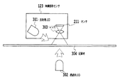
本発明の記録材判別装置およびその方法は、図1に示すような一般的な画像形成装置で用いられる。図1において、画像形成装置101は、用紙カセット102、給紙ローラ103、転写ベルト駆動ローラ104、転写ベルト105、イエロー、マゼンタ、シアン、ブラックの各感光ドラム106〜109、各色用の転写ローラ110〜113、イエロー、マゼンタ、シアン、ブラックの各カートリッジ114〜117、イエロー、マゼンタ、シアン、ブラックの各光学ユニット118〜121、および定着ユニット122を備えている。
Hereinafter, a recording material discriminating apparatus, an image forming apparatus, and a method thereof according to the present invention will be described with reference to the drawings.
(Image forming device)
The recording material discriminating apparatus and method of the present invention are used in a general image forming apparatus as shown in FIG. In FIG. 1, an
画像形成装置101は、一般に電子写真プロセスを用い記録材上にイエロー、マゼンタ、シアン、ブラックの画像を重ねて転写し、定着ローラを含む定着ユニット122によって転写されたトナー画像を温度制御することにより熱定着させる。また、各色の光学ユニット118〜121は、各感光ドラム106〜109の表面をレーザビームによって露光走査して潜像を形成するよう構成され、これら一連の画像形成動作は搬送される記録材上のあらかじめ決まった位置から画像が転写されるよう同期がとられている。
The
さらに、画像形成装置101は記録材であるところの記録紙を給紙、搬送する給紙モータを備え、給紙された記録紙は、転写ベルト、定着ローラへと搬送されながらその表面上に所望の像を形成する。
Further, the
画像読み取りセンサ123は、記録紙が転写ベルトまで搬送される前に配置され、搬送されてきた記録材の表面に光を照射させて、その反射光を集光し結像させて、記録材表面の特定エリアの画像を読み出す。
The
以下に図2を参照して説明する画像形成装置101の制御手段である制御CPU210は、定着ユニット122によって、所望の熱量を記録材に与えることによって、記録材上のトナー画像を融着し定着させる。
A
次に、図2を用いて、本発明の記録材判別装置およびその方法を用いる画像形成装置の一実施形態の制御CPUの動作について説明する。図2は、制御CPU210が制御する各ユニットの構成を示す図である。図2において、CPU210は、CMOSセンサ211、並びに各色用の光学ユニットに含まれるポリゴンミラー、モータおよびレーザ212〜215に接続され、感光ドラム面上にレーザを走査し、所望の潜像を描くための光学ユニットの制御を行う。同様に、記録材を搬送するための給紙モータ216、記録材を給紙するための給紙ローラの駆動開始に使用する給紙ソレノイド217、記録材が所定位置にセットされているか否かを検知する紙有無センサ218、電子写真プロセスに必要な1次帯電、現像、1次転写、2次転写バイアスを制御する高電圧電源219、感光ドラムおよび転写ローラを駆動するドラム駆動モータ220、転写ベルトおよび定着ユニットのローラを駆動するためのベルト駆動モータ221、定着ユニットおよび低電圧電源ユニット122を制御する。さらに、制御CPU210によってサーミスタ(図示せず)により温度をモニタし、定着温度を一定に保つ制御がなされる。
Next, with reference to FIG. 2, the operation of the control CPU of one embodiment of the recording material discrimination apparatus and image forming apparatus using the method of the present invention will be described. FIG. 2 is a diagram showing the configuration of each unit controlled by the
また、制御CPU210は、バス等(図示せず)によりメモリ224に接続されており、メモリ224には、以上の制御および本明細書に記載される各実施形態において制御CPU210が行う処理のすべてまたは一部を実行するためのプログラムおよびデータが格納される。すなわち、制御CPU210はメモリ224に格納されたプログラムおよびデータを用いて本発明の各実施形態の動作を実行する。
The
また、制御CPU210は、バス等(図示せず)によりメモリ223に接続されており、メモリ223には、以上の制御および本明細書に記載される各実施形態において制御CPU210が行う処理のすべてまたは一部を実行するためのプログラムおよびデータが格納される。すなわち、制御CPU210はメモリ223に格納されたプログラムおよびデータを用いて本発明の各実施形態の動作を実行する。
The
ASIC223は、制御CPU210の指示に基づき、CMOSセンサ211および光学ユニット212〜215内部のモータ速度制御、給紙モータの速度制御を行う。モータの速度制御は、モータ(図示せず)からのタック信号を検出して、タック信号の間隔が所定の時間となるようモータに対して加速または減速信号を出力して速度制御を行う。このため、制御回路は ASIC 223のハードウエアによる回路で構成したほうが、CPU210の制御負荷低減が図れるメリットがある。
The
制御CPU210は、ホストコンピュータ(図示せず)からの指示のプリントコマンドを受信すると、紙有無センサ218によって記録材の有無を判断し、紙有りの場合は、給紙モータ216、ドラム駆動モータ220、ベルト駆動モータ221を駆動するとともに、給紙ソレノイド217を駆動して記録材を所定位置まで搬送する。
When the
記録材がCMOSセンサ211の位置まで搬送されると、制御CPU210はASIC 223に対してCMOSセンサ211撮像指示を行い、CMOSセンサ211は記録材の表面画像を撮像する。このときASIC 223は、Sl_selectをアクティブとした後、所定のタイミング、所定パルスのSYSCLKを出力させて、CMOSセンサ211からSl_outを経由して出力される撮像データを取り込む。
When the recording material is conveyed to the position of the
一方、CMOSセンサ211のゲイン設定は、あらかじめ制御CPU210が取り決めた値をASIC 223内部のレジスタにセットすることによって、ASIC 223がSl_selectをアクティブとした後、所定のタイミング、所定パルスのSYSCLKを出力させて、CMOSセンサ211に対し、Sl_inを経由してゲインを設定する。
On the other hand, the gain setting of the
ASIC 223は、以下に説明する本発明の記録材判別装置およびその方法を実現するための回路702を備え、記録材の属性を判別するための後述するの演算の演算結果は、制御回路702内部のレジスタAおよびレジスタBに格納される。そして、CPU 210は、制御回路702内部のレジスタAおよびレジスタBに格納された記録材の属性を判別するための演算結果を読み込み、給紙された記録材の種類を判別し、その結果に応じて画像形成条件を変更するよう制御する。
The
CPU210が実行する各種の画像形成条件の制御としては、以下のようなものが挙げられる。
Examples of the control of various image forming conditions executed by the
例えば、CPU210は、記録材の種類が普通紙よりも光沢度の高いグロス紙の場合は、普通紙よりも現像バイアスを上げ(感光ドラムの表面電位に対する電位差を大きくし)、記録材の表面に付着するトナー量を増加させて記録材上の画像の光沢度を増加させる制御を行う。これは、グロス紙を用いてプリントする場合、記録材上の画像の光沢度を高くすることが望まれているからである。なお、現像バイアス(電圧)は図1に示すように、CPU210の指示に基づいて、高電圧電源219から現像ローラに印加される電圧をいう。
For example, if the type of recording material is glossy paper with a gloss level higher than that of plain paper, the
また、CPU 210は、給紙された記録材の種類に応じて定着ユニット222の定着温度(定着ユニット222内の不図示のヒータが維持すべき目標温度)を変更するよう制御する。普通紙よりも厚みがある厚紙の場合、厚紙は普通紙より熱容量が大きいため普通紙と同じ定着温度にて厚紙にトナー像を定着させようとしても定着性が悪くなってしまうという問題がある。そこで、CPU210は、記録材が厚紙であると判別した場合には、普通紙における定着温度よりも高い定着温度として、厚紙に対するトナーの定着性を確保するよう制御する。
Further, the
さらに、CPU 210は、給紙された記録材の種類を判別し、その結果に応じて記録材の搬送速度を変更するように制御する。搬送速度の制御は、速度を実際に制御しているASIC223の速度制御レジスタ値をCPU 210によって設定しなおすことによって実現する。具体的には、記録材の種類が普通紙よりも厚みがある厚紙の場合、厚紙は普通紙より熱容量が大きいため普通紙と同じ搬送速度にて厚紙にトナー像を定着させようとしても定着性が悪くなってしまうという問題がある。そこで、CPU210は記録材の種類が厚紙であると判別した場合は、単位時間あたりに厚紙に供給される熱量が大きくなるように、記録材の搬送速度を普通紙を通紙する場合の搬送速度よりも遅く設定する。
Further, the
また、坪量が異なる記録材に対し定着温度条件を変え、例えば、比較的厚みのある記録材では、熱容量が大きいので定着温度を高めに制御し、一方、比較的厚みが少ない、つまり熱容量が小さい記録材は、定着温度を低めにして定着する方法も考えられる。または、記録材の坪量によって記録材搬送速度を変えて制御することもできる。 In addition, the fixing temperature condition is changed for recording materials having different basis weights.For example, in a recording material having a relatively large thickness, the heat capacity is large, so the fixing temperature is controlled to be high. A method for fixing a small recording material at a low fixing temperature is also conceivable. Alternatively, the recording material conveyance speed can be changed and controlled according to the basis weight of the recording material.
また、OHTあるいはグロス紙などの場合において、これらを判別して記録材の表面に付着するトナーの定着性を上げ、グロスを高めて画質の向上を図ることもできる。 Further, in the case of OHT or glossy paper, it is possible to improve the image quality by discriminating these and improving the fixability of the toner adhering to the surface of the recording material and increasing the gloss.
このように本実施形態では、CMOSエリアセンサによって撮像した記録材の表面画像から、ASICによるハード回路によって、第一の演算および第二の演算を行い、その結果からCPUは、高伝圧電源の現像バイアス条件、あるいは定着ユニットの定着温度、あるいは記録材の搬送速度を変更するように制御することができる。 As described above, in the present embodiment, the first calculation and the second calculation are performed by the ASIC hardware circuit from the surface image of the recording material imaged by the CMOS area sensor, and the result is that the CPU is the high voltage transmission power supply. It is possible to control to change the developing bias condition, the fixing temperature of the fixing unit, or the recording material conveyance speed.
[第1実施形態]
次に、本願発明の一実施形態による記録材判別装置について説明する。図3は、記録材の表面平滑性及び反射光量及び透過光量検出を行うための概略構成を示す模式図であり、本発明を最もよく表す図であるということができる。
[First Embodiment]
Next, a recording material discrimination device according to an embodiment of the present invention will be described. FIG. 3 is a schematic diagram illustrating a schematic configuration for detecting the surface smoothness, the reflected light amount, and the transmitted light amount of the recording material, and can be said to be the diagram that best represents the present invention.
映像読取センサ123は、図3に示すように、第一の照射手段である反射用LED301、記録材304に対して反対側に設置された透過光量検出用の第二の照射手段である透過用LED302、読み取り手段であるCMOSエリアセンサ211、および結像レンズ303を備える。ここで、センサ211はCCDセンサとすることができる。
As shown in FIG. 3, the
反射用LED301を光源とする光は、記録材304の表面に向けて照射される。本実施形態では光源をLEDとしたが、例えばキセノン管やハロゲンランプ等を用いることもできる。記録材304からの反射光は、レンズ303を介し集光されてCMOSエリアセンサ211に結像する。これによって記録材304の表面の映像を読み取ることができる。
Light using the reflective LED 301 as a light source is emitted toward the surface of the recording material 304. In this embodiment, the light source is an LED, but a xenon tube, a halogen lamp, or the like can also be used. The reflected light from the recording material 304 is condensed through the lens 303 and forms an image on the
本実施形態では、LED301は、LED光が記録材304表面に対し、図3に示すように所定の角度をもって斜めより光を照射させるよう配置されている。 In the present embodiment, the LED 301 is disposed so that the LED light irradiates the recording material 304 with light at an angle as shown in FIG.
(記録材の種類の判別)
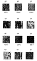
図4は、映像読取センサ123のCMOSエリアセンサ211によって読み取られる記録材304の表面のアナログ画像とCMOSエリアセンサ211からの出力を8×8ピクセルにデジタル処理したデジタル画像との対比を示す図である。ここで、デジタル処理はCMOSエリアセンサ211からのアナログ出力をA/D変換によって8ビットのピクセルデータに変換することによって行われる。
(Determination of recording material type)
FIG. 4 is a diagram showing a comparison between an analog image on the surface of the recording material 304 read by the
図4において、記録材A401は表面の紙の繊維が比較的がさついている所謂ラフ紙、記録材B402は一般に使用される所謂普通紙、記録材C403は紙の繊維の圧縮が十分になされているグロス紙であり、それぞれの表面拡大映像である。CMOSセンサ211に読み込まれたこれらの映像401〜403が、デジタル処理され図4に示す映像404〜406となる。このように、記録材の種類によって表面の映像は異なる。これは、主に紙の表面における繊維の状態が異なるために起こる現象である。
In FIG. 4, the recording material A401 is a so-called rough paper in which the paper fibers on the surface are relatively sandwiched, the recording material B402 is a so-called plain paper that is generally used, and the recording material C403 is sufficiently compressed in the paper fibers. It is a gloss paper, and each is an enlarged image of the surface. These
これとは別に、記録材の反射光量は、一般にそれぞれの画素に入力された光の合計もしくは平均値から算出するが、実施例によっては、1受光画素の結果のみを用いることもできる。 Apart from this, the amount of reflected light of the recording material is generally calculated from the total or average value of the light input to each pixel. However, depending on the embodiment, only the result of one light receiving pixel can be used.
上述のように、CMOSエリアセンサ211で記録材表面を読み込んだ結果の映像をデジタル処理した像により、記録材の紙繊維の表面状態を識別することができ、これに加え反射光量によって記録材の判別が可能となる。
As described above, the surface state of the paper fiber of the recording material can be identified by an image obtained by digitally processing the image obtained by reading the surface of the recording material by the
上記記録材表面の識別は、記録材の表面の一部を8×8ピクセルからなる映像として読み込み、映像において記録材の搬送方向に直交する方向の1ラインについて最大濃度となる画素の濃度Dmaxと最低濃度となる画素の濃度Dminを検出し、各ラインについてDmax−Dminを平均処理する。そして、平均処理して得られたDmax−Dminの値によって、その記録材の属性である材質(平滑度)を判定することができる。 The recording material surface is identified by reading a part of the surface of the recording material as an image composed of 8 × 8 pixels, and the pixel density Dmax that is the maximum density for one line in the direction orthogonal to the recording material conveyance direction in the image. The density Dmin of the pixel having the lowest density is detected, and Dmax−Dmin is averaged for each line. The material (smoothness) that is an attribute of the recording material can be determined based on the value of Dmax−Dmin obtained by the averaging process.
すなわち、記録材Aのように表面の紙繊維がガサついている場合には、繊維の影が多く発生する。その結果、明るい個所と暗い個所の差が大きく出るため、Dmax−Dminは大きくなる。一方、記録材Cのように繊維が十分圧縮され平滑度の高い記録材の表面の映像は、繊維の影が少なく、Dmax−Dminは小さくなる。この比較によって、記録材の材質を判定し、種類を判別するための情報の一部とするのである。 That is, when the paper fiber on the surface is rough like the recording material A, many shadows of the fiber are generated. As a result, the difference between the bright part and the dark part is large, and Dmax−Dmin becomes large. On the other hand, the image of the surface of a recording material having a sufficiently smooth fiber and a high smoothness like the recording material C has less fiber shadow and Dmax−Dmin becomes small. By this comparison, the material of the recording material is determined and used as a part of information for determining the type.
同様に、図4において、映像407は、薄紙である記録紙Dの透過用LED302により記録材を透過してきた光の光照射領域における表面拡大映像であり、映像408は、一般的に使用される所謂普通紙である記録紙Eの透過用LED302による光照射領域の表面拡大映像であり、映像409は、厚紙である記録紙Fの透過用LED302による光照射領域の表面拡大映像である。CCDセンサ211に読み込まれたこれらの映像407〜409が、デジタル処理され図4の映像410〜412となる。
Similarly, in FIG. 4, an
このように、記録紙の種類によって、透過光量およびその映像は異なってくる。これは、主に紙の表面における繊維の状態および紙の繊維の圧縮状態が異なるために起こる現象である。 In this way, the amount of transmitted light and its image vary depending on the type of recording paper. This is a phenomenon that occurs mainly because the fiber state on the paper surface and the compressed state of the paper fiber are different.
上述の制御プロセッサは、CMOSエリアセンサ211からの映像サンプリング処理、ゲイン及びフィルタ演算処理をリアルタイムにて処理する必要があるため、デジタルシグナルプロセッサを用いることが望ましい。
Since the above-described control processor needs to process video sampling processing, gain and filter calculation processing from the
次に、記録材304の透過率測定方法について説明する。第二の照射手段である透過用LED302を光源とする光は、記録材304に向けて映像読取センサ123の反対側から、記録材上の映像読取センサ123の読取エリアに入射するように照射される。
Next, a method for measuring the transmittance of the recording material 304 will be described. The light that uses the transmitting LED 302 as the second irradiation means as a light source is irradiated toward the recording material 304 from the opposite side of the
図5は、透過用LED302を用いて、映像読取センサ123のCMOSエリアセンサ211によって読み取られる記録材304の表面を、CMOSエリアセンサ211からの出力を8×8ピクセルにデジタル処理して示した図である。記録材304の透過光は、レンズ303を介し集光されてCMOSエリアセンサ211に入射する。このとき、通常は、センサのエリア全体、もしくは所定の範囲において各画素に入力した光量の合計値もしくは平均値を透過光量とするが、1受光画素の結果のみを用いることもできる。
FIG. 5 is a diagram showing the surface of the recording material 304 read by the
図6は、記録材の坪量と透過光の関係を示す図である。例えば、厚紙のように坪量の多い記録材は透過光量が少ない、一方薄紙のような坪量の低い記録材は透過光量が多い。この特性によって、記録材の属性の1つである材厚を透過光量によって判定し、記録材の種類を判別する情報の1つとするのである。 FIG. 6 is a diagram showing the relationship between the basis weight of the recording material and the transmitted light. For example, a recording material with a large basis weight such as thick paper has a small amount of transmitted light, whereas a recording material with a low basis weight such as thin paper has a large amount of transmitted light. Based on this characteristic, the material thickness, which is one of the attributes of the recording material, is determined based on the amount of transmitted light, which is one piece of information for determining the type of the recording material.
本実施形態で想定する記録材の種類には、以下のようなものがあり、次に説明するように表面の状態や材厚によってその種類を判別する。なお、以下に述べる坪量とは、記録材の単位体積あたりの重量をいう。
(1)薄紙(坪量:単位面積あたりの重量〜64g/m2)
(2)普通紙(坪量:65〜105g/m2)
(3)厚紙1(坪量:106〜135g/m2)
(4)厚紙2(坪量:136g/m2〜)
(5)グロス紙
(6)グロスフィルム
(7)OHT
There are the following types of recording materials assumed in the present embodiment, and the type is determined according to the surface state and the material thickness as will be described below. The basis weight described below refers to the weight per unit volume of the recording material.
(1) Thin paper (basis weight: weight per unit area to 64 g / m 2 )
(2) Plain paper (basis weight: 65 to 105 g / m 2 )
(3) Cardboard 1 (basis weight: 106 to 135 g / m 2 )
(4) Cardboard 2 (basis weight: 136 g / m 2 ~)
(5) Gloss paper (6) Gloss film (7) OHT
記録材からの反射光量によって判定されるのは、(7)は透明で光の透過率が高いため、(1)〜(6)、(7)という2組である。 Since (7) is transparent and has high light transmittance, two sets (1) to (6) and (7) are determined based on the amount of light reflected from the recording material.
記録材の反射光から得られた映像による濃淡比から判定されるのは、(1)〜(4)、(5)、(6)という3組である。ここで、本実施形態では、この判定のため濃淡比を検出する際、反射光量による正規化をする。すなわち、2次元画像の全体の光量に差があるとDmax−Dminの値も変わってきてしまうので、2次元画像全体の光量の平均値が一致するように正規化する。 Three sets (1) to (4), (5), and (6) are determined from the contrast ratio of the image obtained from the reflected light of the recording material. Here, in this embodiment, when detecting the light / dark ratio for this determination, normalization is performed based on the amount of reflected light. That is, if there is a difference in the total light amount of the two-dimensional image, the value of Dmax−Dmin also changes, so normalization is performed so that the average value of the light amount of the entire two-dimensional image matches.
透過光量によって判定されるのは、(1)〜(4)の坪量がそれぞれ異なっており、一定の光量を紙の背面から照射した場合の透過光の受光光量は、(1)>(2)>(3)>(4)となるため、(1)、(2)、(3)、(4)の4種となる。ここで、本実施形態においては、8×8ピクセルからなる全画素の透過光量の平均値を用いて判定を行う。 The basis weights of (1) to (4) are different depending on the amount of transmitted light, and the received light amount of transmitted light when a constant amount of light is irradiated from the back of the paper is (1)> (2 )> (3)> (4), so that there are four types (1), (2), (3), and (4). Here, in the present embodiment, the determination is performed using the average value of the transmitted light amount of all the pixels including 8 × 8 pixels.
以上の判定を組み合わせることによって、(1)〜(7)の多様な記録材を正確に判別することができる。 By combining the above determinations, various recording materials (1) to (7) can be accurately determined.
(記録材判別機能の実装)
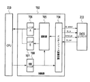
以上の動作を行うためのCMOSエリアセンサ211の制御回路を図7を用いて説明する。図7は、CMOSエリアセンサ211の制御回路を示すブロック図である。図7において、判断部であるCPU210は、制御回路702、CMOSエリアセンサ211、インターフェース制御回路704、演算回路705、レジスタA706、レジスタB707、および制御レジスタ708を備える。
(Implementation of recording material discrimination function)
A control circuit of the
次に動作について説明する。CPU 210は制御レジスタ708に対して、CMOSエリアセンサ211の動作指示を与えると、CMOSエリアセンサ211によって記録材表面画像の撮像が開始される。つまり、CMOSエリアセンサ211に電荷の蓄積が開始される。インターフェース回路704から、Sl_selectによってCMOSエリアセンサ211を選択し、所定のタイミングにてSYSCLKを生成すると、CMOSエリアセンサ211からSl_out信号を経由して、撮像されたデジタル画像データが送信される。
Next, the operation will be described. When the
インターフェース回路704を経由して受信した撮像データは、制御回路702にて演算が実行され、その演算結果がレジスタA 706およびレジスタB 707に格納される。CPU 210は、上記2つのレジスタの値から、記録材の属性を判定する。
The imaging data received via the
なお、レジスタA706に格納される値は、CMOSエリアセンサ211が映像として取得した記録材の表面の一部について、8ライン分のDmax−Dminを平均した値であり、この映像を取得する際には、LED301が記録材の表面を照射している。また、レジスタB707に格納される値は、CMOSエリアセンサ211が映像として取得した記録材の表面の一部について、8×8ピクセルの各ピクセルの光量を平均した値であり、この映像を取得する際には、透過用LED302が記録材の裏面を照射している。
The value stored in the register A706 is a value obtained by averaging Dmax−Dmin for 8 lines for a part of the surface of the recording material acquired as an image by the
次に、図8を用いてセンサ回路ブロック図について説明する。図8は、CMOSエリアセンサの回路ブロック図を示す図である。図8において、CMOSエリアセンサ211は、CMOSセンサ部分801を含み、例えば8×8画素分のセンサがエリア状に配置される。CMOSエリアセンサ211は、さらに垂直方向シフトレジスタ802および803、出力バッファ804、水平方向シフトレジスタ805、システムクロック806、およびタイミングジェネレータ807を含む。
Next, a sensor circuit block diagram will be described with reference to FIG. FIG. 8 is a circuit block diagram of the CMOS area sensor. In FIG. 8, a
次に動作について説明する。Sl_select信号813をアクティブとすると、CMOSセンサ部801は受光した光に基づく電荷の蓄積を開始する。次に、システムクロック806を与えると、タイミングジェネレータ807によって、垂直方向シフトレジスタ802および803は読みだす画素の列を順次選択され、出力バッファ804にデータを順次格納される。
Next, the operation will be described. When the
出力バッファ804に格納されたデータは、水平方向シフトレジスタ805によって、A/Dコンバータ808ヘと転送される。A/Dコンバータ808でデジタル変換された画素データは、出力インターフェース回路809によって所定のタイミングで制御され、Sl_select信号813がアクティブの期間、Sl_out 信号810に出力される。
Data stored in the
一方、811の制御回路によって、Sl_in信号812よりA/D変換ゲインを変更するよう制御することができる。例えば、撮像した画像のコントラストが得られない場合は、CPUはゲインを変更して常に最良なコントラストで撮像することができる。
On the other hand, the
このように、第一の照射手段である反射用LED301と、第二の照射手段である透過用LED302との2つの照射手段を用いることによって、様々な記録材の表面状態、反射率および透過率を検出することができ記録材の種類の判別が可能となる。 As described above, by using the two irradiation means, that is, the reflection LED 301 as the first irradiation means and the transmission LED 302 as the second irradiation means, the surface state, reflectance, and transmittance of various recording materials. Can be detected, and the type of recording material can be determined.
本実施形態において、透過用LED302の波長は反射用LED301よりも長い光源を用いる。例えば、反射用LED301が可視光であれば透過用LED302は赤外線を用いることができる。 In the present embodiment, a light source having a wavelength longer than that of the reflective LED 301 is used for the transmissive LED 302. For example, if the reflective LED 301 is visible light, the transmissive LED 302 can use infrared rays.
図9に透過用LED302として、波長の異なる可視光あるいは赤外光LEDを用いた記録材透過特性を示す。図9に示されるように、波長の長いLEDを光源に用いた方が記録材を透過する透過率が高い。従って透過光による記録材の厚み判別を行う場合には、検出のためのダイナミックレンジを広くとることができる波長の長い光源、例えば赤外光LEDを使用することが、精度良く安定した検出を行うために非常に有効である。本発明では、記録材表面からの反射光の検出に用いる反射用照射LEDは、前記CMOSエリアセンサにおいて光感度の最も高い可視光LEDを用い、透過光量検出に用いる透過用LEDは反射用LEDよりも波長の長い、例えば、赤外LEDを用いる実施例とした。これにより、記録材の透過性が高く、S/N比が改善されることによりダイナミックレンジが大きくなり検出信頼性が向上するのである。 FIG. 9 shows recording material transmission characteristics using visible light or infrared light LEDs having different wavelengths as the transmission LED 302. As shown in FIG. 9, the transmittance for transmitting the recording material is higher when an LED having a longer wavelength is used as the light source. Accordingly, when the thickness of the recording material is determined by the transmitted light, a light source having a long wavelength that can take a wide dynamic range for detection, for example, an infrared light LED, can be detected accurately and stably. Is very effective for. In the present invention, the reflective LED used for detecting the reflected light from the surface of the recording material is a visible light LED having the highest photosensitivity in the CMOS area sensor, and the transmissive LED used for detecting the transmitted light quantity is more reflective than the reflective LED. Also, an example using an infrared LED having a long wavelength, for example, is used. As a result, the recording material has high transparency, and the S / N ratio is improved, so that the dynamic range is increased and the detection reliability is improved.
以上、反射型光照射手段である記録材表面撮影用の反射用LEDと、透過光による記録材の厚み検出用の透過型光照射手段である透過用LEDの2つの照射手段を用い、かつ、透過用LEDの波長を、反射用LEDの波長よりも、長波長のLEDを用いることによって、様々な記録材の表面性状態、反射率および透過率を精度良く検出でき、記録材種類の判断が可能となる。 As described above, using the two irradiation means of the reflection LED for recording surface photographing as the reflection light irradiation means and the transmission LED as the transmission light irradiation means for detecting the thickness of the recording material by the transmitted light, and By using an LED having a wavelength longer than that of the LED for reflection, the surface property state, reflectance and transmittance of various recording materials can be accurately detected, and the type of the recording material can be determined. It becomes possible.
[第2実施形態]
第2実施形態において、透過光検出部の構成以外の基本的な構成は、第1実施形態と同様であるため詳細な説明は省略する。本実施形態において透過用LED302は、反射用LED301よりも光強度を強く発光させることを特徴とする。
[Second Embodiment]
In the second embodiment, the basic configuration other than the configuration of the transmitted light detection unit is the same as that of the first embodiment, and a detailed description thereof will be omitted. In the present embodiment, the transmissive LED 302 emits light with a light intensity stronger than that of the reflective LED 301.
CMOSエリアセンサ211の感度ゲインは変えられるものの、デバイスの光感度は固定である。従って、複数の光源においても複数の光源はできれば近い光量であることが検出のダイナミックレンジの共通化とシステムとしてゲインをある範囲に特定しやすいため、精度よく最適化する検出系を構成することが可能となる。一般に、記録材表面で反射して受光される光量よりも、記録材を透過させて透過光を検出する方が光量が少なく、特に、厚い記録材を精度良く検出するためには、検出のためのダイナミックレンジを広くするために光量を上げることが望ましい。このことによりS/N比が改善されダイナミックレンジが大きくなり検出信頼性を向上させることが可能となる。
Although the sensitivity gain of the
以上、記録材表面撮影用のLEDと、透過光による記録材の厚み検出用の透過用LEDの2つのLEDを用い、かつ、透過用LEDの光量を反射用LEDの光量よりも大きな発光量となるように制御することにより、様々な記録材の表面状態、反射率および透過率を精度良く検出でき、記録材種類の判断が可能となる。 As described above, the LED for recording the surface of the recording material and the LED for transmission for detecting the thickness of the recording material by the transmitted light are used, and the light amount of the LED for transmission is larger than the light amount of the LED for reflection. By controlling in such a manner, it is possible to accurately detect the surface state, reflectance, and transmittance of various recording materials, and to determine the type of recording material.
[第3実施形態]
第3実施形態は、透過光検出部の構成以外の、基本的な構成は第1実施形態と同様であるため詳細な説明は省略する。本実施形態において透過用LED302は、反射用LED301よりも狭い指向性のLEDを用いて構成することを特徴とする。
[Third Embodiment]
In the third embodiment, since the basic configuration other than the configuration of the transmitted light detection unit is the same as that of the first embodiment, detailed description thereof is omitted. In this embodiment, the transmissive LED 302 is configured by using an LED having a narrower directivity than the reflective LED 301.
CMOSエリアセンサ211の感度ゲインは変えられるものの、デバイスの光感度は固定である。従って、複数の光源においても複数の光源はできれば近い光量であることが検出のダイナミックレンジの共通化とシステムとしてゲインをある範囲に特定しやすいため、精度よく最適化する検出系を構成することが可能となる。一般に記録材表面で反射して受光される光量よりも、記録材を透過させて透過光を検出する方が光量が少ない。特に、厚い記録紙を精度良く検出するためには、検出のためのダイナミックレンジを広くするために光量を上げることが望ましい。第2実施形態で示すように透過用LED302の光量を大きくする方法では、LEDデバイスに大きな電流で駆動しなければならず、LEDもコストアップする場合がある。
Although the sensitivity gain of the
第3実施形態では、この問題を狭い指向性のLEDを用いて解決する。図10に示すようにLEDデバイスには指向性の広い(弱い)ものと、指向性の狭い(強い)ものが存在する。狭い指向性のLEDを用いればLEDの駆動電流を大きく変えることなく光を集中することができ、単位面積あたりの光量を増大させることができるため、透過光検出に用いる透過用の光源として好適である。本実施形態ではLEDデバイスとして指向性の異なるものの例を挙げ狭い指向性のものを用いる構成を提案した。しかし、LEDは同じ指向性のものを用いてLEDの前面に別部品でレンズを配置構成することにより同機能を実現する方式でもよい。このことによりS/N比が改善されダイナミックレンジが大きくなり検出信頼性を向上させることが可能となる。 In the third embodiment, this problem is solved by using a narrow directivity LED. As shown in FIG. 10, there are LED devices having wide directivity (weak) and narrow directivity (strong). If a narrow directivity LED is used, the light can be concentrated without greatly changing the LED drive current, and the amount of light per unit area can be increased. Therefore, it is suitable as a light source for transmission used for transmitted light detection. is there. In the present embodiment, an example of LED devices with different directivities is given and a configuration using narrow directivity is proposed. However, the LED may have the same directivity, and a system that realizes the same function by disposing a lens as a separate component on the front surface of the LED may be used. As a result, the S / N ratio is improved, the dynamic range is increased, and the detection reliability can be improved.
以上、記録材表面撮影用のLEDと、透過光による記録材の厚み検出用のLEDの2つのLEDを用い、かつ、透過用LEDの光量を反射用LEDの光量よりも狭い指向性のLEDを用いてLED駆動を行うように制御することにより、様々な記録材の表面状態、反射率および透過率を精度良く検出でき、記録材種類の判断が可能となる。 As described above, the LED for recording the surface of the recording material and the LED for detecting the thickness of the recording material by transmitted light are used, and the LED having the directivity narrower than the light amount of the reflecting LED is used. By using and controlling to perform LED driving, it is possible to accurately detect the surface state, reflectance, and transmittance of various recording materials, and to determine the type of recording material.
101 画像形成装置
102 用紙カセット
103 給紙ローラ
104 転写ベルト駆動ローラ
105 転写ベルト
106〜109 イエロー、マゼンタ、シアン、ブラックの各感光ドラム
110〜113 各色用の転写ローラ
114〜117 イエロー、マゼンタ、シアン、ブラックの各カートリッジ
118〜121 イエロー、マゼンタ、シアン、ブラックの各光学ユニット
122 定着ユニット
123 画像読取センサ
210 制御CPU
211 CMOSセンサ
212〜215 ポリゴンミラー、モータおよびレーザ
216 給紙モータ
217 給紙ソレノイド
218 紙有無センサ
219 高電圧電源
220 ドラム駆動モータ
221 ベルト駆動モータ
222 低電圧電源
223 ASIC
224 メモリ
301 反射用LED
302 透過用LED
303 レンズ
304 記録材
702 制御回路
704 インターフェース制御回路
705 演算回路
706 レジスタA
707 レジスタB
708制御レジスタ
801 CMOSセンサ部分
802、803 垂直方向シフトレジスタ
804 出力バッファ
805 水平方向シフトレジスタ
806 システムクロック
807 タイミングジェネレータ
808 A/Dコンバータ
809 出力インターフェース回路
810 Sl_out 信号
811 制御回路
812 Sl_in信号
813 Sl_select信号
DESCRIPTION OF
211
224 Memory 301 LED for reflection
302 LED for transmission
303 Lens 304
707 Register B
708 Control register 801
Claims (12)
前記反射型判定手段において用いられる照射光よりも長い波長を有する所定の照射光を前記記録材に照射することにより、該記録材を透過して得られる透過光を用いて、前記記録材の前記反射型判定手段とは異なる属性を判定する透過型判定手段を備え、
前記反射型判定手段により得られた属性に加えて、前記透過型判定手段により得られた属性に基づいて前記記録材の種類を判別することを特徴とする記録材判別装置。 Including image reading means for obtaining an image of the surface of the recording material by irradiating the recording material with light and reading reflected light reflected from the surface of the recording material, and using the image of the surface of the recording material obtained by the image reading means In the recording material discriminating apparatus for determining the type of the recording material based on the attribute obtained by the reflection type judging means, comprising a reflection type judging means for judging a predetermined attribute of the recording material,
By irradiating the recording material with predetermined irradiation light having a wavelength longer than the irradiation light used in the reflection type determination means, the transmitted light obtained through the recording material is used, and the recording material A transmission type determination means for determining an attribute different from the reflection type determination means;
A recording material discriminating apparatus for discriminating the type of the recording material based on the attribute obtained by the transmission type judging means in addition to the attribute obtained by the reflection type judging means.
前記反射型判定手段において用いられる照射光よりも強い光量の所定の照射光を前記記録材に照射することにより、該記録紙を透過して得られる透過光であって、該所定の照射光の光量を調整することにより前記反射光の光量と該透過光の光量との差が所定の範囲内となる透過光を用いて、前記記録材の前記反射型判定手段とは異なる属性を判定する透過型判定手段を備え、
前記反射型判定手段により得られた属性に加えて、前記透過型判定手段により得られた属性に基づいて前記記録材の種類を判別することを特徴とする記録材判別装置。 Including image reading means for obtaining an image of the surface of the recording material by irradiating the recording material with light and reading reflected light reflected from the surface of the recording material, and using the image of the surface of the recording material obtained by the image reading means In the recording material discriminating apparatus for determining the type of the recording material based on the attribute obtained by the reflection type judging means, comprising a reflection type judging means for judging a predetermined attribute of the recording material,
By irradiating the recording material with predetermined irradiation light having a light intensity stronger than the irradiation light used in the reflection type determination means, the transmitted light is transmitted through the recording paper, Transmission that determines an attribute different from that of the reflection type determination unit of the recording material by using transmitted light in which the difference between the amount of reflected light and the amount of transmitted light is within a predetermined range by adjusting the amount of light With a type determining means,
A recording material discriminating apparatus for discriminating the type of the recording material based on the attribute obtained by the transmission type judging means in addition to the attribute obtained by the reflection type judging means.
前記記録材を透過する透過光を得るため前記記録材に前記反射型照射手段で照射される所定の光よりも長い波長を有する所定の光を照射する透過型照射手段を備え、
前記制御手段は、前記反射型照射手段と前記透過型照射手段とに前記記録材へ光を照射させ、前記読み取り手段に前記反射型照射手段により得られた反射光を映像として読み取らせ、および前記透過型照射手段により得られた透過光の光量を検出させて、該映像と該透過光の光量とに基づいて前記記録材の種類を判別することを特徴とする記録材判別装置。 In order to obtain reflected light reflected from the surface of the recording material, a reflection type irradiating means for irradiating the recording material with predetermined light, reflected light or transmitted light from the recording material is received and read as an image, and the amount of light is detected. Reading means, and causing the reflection type irradiation means to irradiate the recording material with light, causing the reading means to read the reflected light obtained by the reflection type irradiation means as an image, and based on the image, In the recording material discriminating apparatus provided with the control means for discriminating the type,
In order to obtain transmitted light that passes through the recording material, the recording material includes transmission type irradiation means for irradiating predetermined light having a wavelength longer than the predetermined light irradiated by the reflection type irradiation means,
The control unit causes the reflection type irradiation unit and the transmission type irradiation unit to irradiate the recording material with light, causes the reading unit to read reflected light obtained by the reflection type irradiation unit as an image, and A recording material discriminating apparatus characterized in that the amount of transmitted light obtained by the transmission type irradiation means is detected and the type of the recording material is discriminated based on the image and the amount of transmitted light.
前記記録材を透過する透過光を得るため前記記録材に前記反射型照射手段で照射される所定の光よりも強い光量の所定の光であって、該所定の光の光量を調整することにより前記反射光の光量と該透過光の光量との差が所定の範囲内となる所定の光を照射する透過型照射手段を備え、
前記制御手段は、前記反射型照射手段と前記透過型照射手段とに前記記録材へ光を照射させ、前記読み取り手段に前記反射型照射手段により得られた反射光を映像として読み取らせ、および前記透過型照射手段により得られた透過光の光量を検出させて、該映像と該透過光の光量とに基づいて前記記録材の種類を判別することを特徴とする記録材判別装置。 In order to obtain reflected light reflected from the surface of the recording material, a reflection type irradiating means for irradiating the recording material with predetermined light, reflected light or transmitted light from the recording material is received and read as an image, and the amount of light is detected. Reading means, and causing the reflection type irradiation means to irradiate the recording material with light, causing the reading means to read the reflected light obtained by the reflection type irradiation means as an image, and based on the image, In the recording material discriminating apparatus provided with the control means for discriminating the type,
In order to obtain transmitted light that passes through the recording material, the recording material is a predetermined amount of light that is stronger than the predetermined light irradiated by the reflection type irradiation means, and the light amount of the predetermined light is adjusted. A transmission type irradiation means for irradiating predetermined light in which a difference between the light amount of the reflected light and the light amount of the transmitted light is within a predetermined range;
The control unit causes the reflection type irradiation unit and the transmission type irradiation unit to irradiate the recording material with light, causes the reading unit to read reflected light obtained by the reflection type irradiation unit as an image, and A recording material discriminating apparatus characterized in that the amount of transmitted light obtained by the transmission type irradiation means is detected and the type of the recording material is discriminated based on the image and the amount of transmitted light.
前記反射型判定手段において用いられる照射光よりも長い波長を有する所定の照射光を前記記録材に照射することにより、該記録材を透過して得られる透過光を用いて、前記記録材の前記反射型判定手段とは異なる属性を判定する透過型判定手段を備え、
前記定着手段は、前記反射型判定手段により得られた属性に加えて、前記透過型判定手段により得られた属性に基づいて前記記録材の種類を判別し、当該判別された種類に対応する前記定着処理条件により前記現像剤像を記録材に定着させることを特徴とする画像形成装置。 A latent image carrier for carrying a latent image, a developing means for visualizing the latent image as a developer image by applying a developer to the latent image carrier, and a developing means for recording material conveyed in a predetermined direction A transfer means for transferring the developer image according to the method, and fixing the developer image on the recording material by heating and pressurizing the recording material on which the developer image has been transferred by the transfer means under predetermined fixing processing conditions. A fixing unit; and a video reading unit that obtains an image of the surface of the recording material by irradiating the recording material with light and reading reflected light reflected from the surface of the recording material, and the recording material surface obtained by the video reading unit Reflection type determination means for determining a predetermined attribute of the recording material using the image of the recording material, and determining the type of the recording material based on the attribute obtained by the reflection type determination means, and to the determined type Corresponding said In the image forming apparatus to be fixed on the recording material the toner image by coating treatment conditions,
By irradiating the recording material with predetermined irradiation light having a wavelength longer than the irradiation light used in the reflection type determination means, the transmitted light obtained through the recording material is used, and the recording material A transmission type determination means for determining an attribute different from the reflection type determination means;
The fixing unit determines the type of the recording material based on the attribute obtained by the transmission type determination unit in addition to the attribute obtained by the reflection type determination unit, and corresponds to the determined type. An image forming apparatus, wherein the developer image is fixed on a recording material according to fixing processing conditions.
前記反射型判定手段において用いられる照射光よりも強い光量の所定の照射光を前記記録材に照射することにより、該記録紙を透過して得られる透過光であって、該所定の照射光の光量を調整することにより前記反射光の光量と該透過光の光量との差が所定の範囲内となる透過光を用いて、前記記録材の前記反射型判定手段とは異なる属性を判定する透過型判定手段を備え、
前記定着手段は、前記反射型判定手段により得られた属性に加えて、前記透過型判定手段により得られた属性に基づいて前記記録材の種類を判別し、当該判別された種類に対応する前記定着処理条件により前記現像剤像を記録材に定着させることを特徴とする画像形成装置。 A latent image carrier for carrying a latent image, a developing means for visualizing the latent image as a developer image by applying a developer to the latent image carrier, and a developing means for recording material conveyed in a predetermined direction A transfer means for transferring the developer image according to the method, and fixing the developer image on the recording material by heating and pressurizing the recording material on which the developer image has been transferred by the transfer means under predetermined fixing processing conditions. A fixing unit; and a video reading unit that obtains an image of the surface of the recording material by irradiating the recording material with light and reading reflected light reflected from the surface of the recording material, and the recording material surface obtained by the video reading unit Reflection type determination means for determining a predetermined attribute of the recording material using the image of the recording material, and determining the type of the recording material based on the attribute obtained by the reflection type determination means, and to the determined type Corresponding said In the image forming apparatus to be fixed on the recording material the toner image by coating treatment conditions,
By irradiating the recording material with predetermined irradiation light having a light intensity stronger than the irradiation light used in the reflection type determination means, the transmitted light is transmitted through the recording paper, Transmission that determines an attribute different from that of the reflection type determination unit of the recording material by using transmitted light in which the difference between the amount of reflected light and the amount of transmitted light is within a predetermined range by adjusting the amount of light With a type determining means,
The fixing unit determines the type of the recording material based on the attribute obtained by the transmission type determination unit in addition to the attribute obtained by the reflection type determination unit, and corresponds to the determined type. An image forming apparatus, wherein the developer image is fixed on a recording material according to fixing processing conditions.
前記記録材を透過する透過光を得るため前記記録材に前記反射型照射手段で照射される所定の光よりも長い波長を有する所定の光を照射する透過型照射手段を備え、
前記制御手段は、前記転写手段で転写させる前に、前記反射型照射手段と前記透過型照射手段とに前記記録材へ光を照射させ、前記読み取り手段に前記反射型照射手段により得られた反射光を映像として読み取らせ、および前記透過型照射手段により得られた透過光の光量を検出させて、該映像と該透過光の光量とに基づいて前記記録材の種類を判別し、当該判別された種類に対応する前記定着処理条件により前記現像剤像を記録材に定着させることを特徴とする画像形成装置。 A latent image carrier for carrying a latent image, a developing means for applying a developer to the latent image carrier, a transfer means for transferring the developer image to a recording material, and the developer image by heating and pressing. A fixing means for fixing the recording material to the recording material, a reflective irradiation means for irradiating the recording material with predetermined light to obtain reflected light reflected from the surface of the recording material, and the latent image as a developer image by the developing means. Reading that visualizes and transfers the visualized image to the recording material conveyed in a predetermined direction by the transfer means, receives reflected light or transmitted light from the recording material, reads it as an image, and detects the amount of light And the reflection type irradiation means irradiates the recording material with light, the reading means reads the reflected light obtained by the reflection type irradiation means as an image, and the type of the recording material is determined based on the image. Discriminate In predetermined fixing treatment condition corresponding to another is the type to fix the recording material which has been transferred by said fixing means, an image forming apparatus having a control means for discharging the fixed recording material,
In order to obtain transmitted light that passes through the recording material, the recording material includes transmission type irradiation means for irradiating predetermined light having a wavelength longer than the predetermined light irradiated by the reflection type irradiation means,
The control unit irradiates the recording material with light to the reflection type irradiation unit and the transmission type irradiation unit before transferring by the transfer unit, and causes the reading unit to reflect the reflection type obtained by the reflection type irradiation unit. The light is read as an image, and the amount of transmitted light obtained by the transmission type irradiation means is detected, and the type of the recording material is determined based on the image and the amount of transmitted light. An image forming apparatus, wherein the developer image is fixed on a recording material according to the fixing processing condition corresponding to the type.
前記記録材を透過する透過光を得るため前記記録材に前記反射型照射手段で照射される所定の光よりも強い光量の所定の光であって、該所定の光の光量を調整することにより前記反射光の光量と該透過光の光量との差が所定の範囲内となる所定の光を照射する透過型照射手段を備え、
前記制御手段は、前記転写手段で転写させる前に、前記反射型照射手段と前記透過型照射手段とに前記記録材へ光を照射させ、前記読み取り手段に前記反射型照射手段により得られた反射光を映像として読み取らせ、および前記透過型照射手段により得られた透過光の光量を検出させて、該映像と該透過光の光量とに基づいて前記記録材の種類を判別し、当該判別された種類に対応する前記定着処理条件により前記現像剤像を記録材に定着させることを特徴とする画像形成装置。 A latent image carrier for carrying a latent image, a developing means for applying a developer to the latent image carrier, a transfer means for transferring the developer image to a recording material, and the developer image by heating and pressing. Fixing means for fixing the recording material to the recording material, reflection type irradiation means for irradiating the recording material with predetermined light to obtain reflected light reflected from the surface of the recording material, and developing the latent image as a developer image Reading that visualizes and transfers the visualized image to the recording material transported in a predetermined direction by the transfer means, receives reflected light or transmitted light from the recording material as an image, and detects the amount of light And the reflection type irradiation means irradiates the recording material with light, the reading means reads the reflected light obtained by the reflection type irradiation means as an image, and the type of the recording material is determined based on the image Discriminate In predetermined fixing treatment condition corresponding to another is the type to fix the recording material which has been transferred by said fixing means, an image forming apparatus having a control means for discharging the fixed recording material,
In order to obtain transmitted light that passes through the recording material, the recording material is a predetermined amount of light that is stronger than the predetermined light irradiated by the reflection type irradiation means, and the light amount of the predetermined light is adjusted. A transmission type irradiation means for irradiating predetermined light in which a difference between the light amount of the reflected light and the light amount of the transmitted light is within a predetermined range;
The control unit irradiates the recording material with light to the reflection type irradiating unit and the transmission type irradiating unit before transferring by the transfer unit, and causes the reading unit to obtain the reflection obtained by the reflective type irradiating unit. The light is read as an image, and the amount of transmitted light obtained by the transmission type irradiation means is detected, and the type of the recording material is determined based on the image and the amount of transmitted light. An image forming apparatus, wherein the developer image is fixed on a recording material according to the fixing processing condition corresponding to the type.
The image forming apparatus according to claim 11, wherein the predetermined light of the transmission type irradiation unit uses a light source having higher directivity than the predetermined light used in the reflection type irradiation unit.
Priority Applications (1)
| Application Number | Priority Date | Filing Date | Title |
|---|---|---|---|
| JP2003346279A JP2005114866A (en) | 2003-10-03 | 2003-10-03 | Recording material discrimination device and image forming device |
Applications Claiming Priority (1)
| Application Number | Priority Date | Filing Date | Title |
|---|---|---|---|
| JP2003346279A JP2005114866A (en) | 2003-10-03 | 2003-10-03 | Recording material discrimination device and image forming device |
Publications (2)
| Publication Number | Publication Date |
|---|---|
| JP2005114866A true JP2005114866A (en) | 2005-04-28 |
| JP2005114866A5 JP2005114866A5 (en) | 2006-11-16 |
Family
ID=34539281
Family Applications (1)
| Application Number | Title | Priority Date | Filing Date |
|---|---|---|---|
| JP2003346279A Pending JP2005114866A (en) | 2003-10-03 | 2003-10-03 | Recording material discrimination device and image forming device |
Country Status (1)
| Country | Link |
|---|---|
| JP (1) | JP2005114866A (en) |
Cited By (6)
| Publication number | Priority date | Publication date | Assignee | Title |
|---|---|---|---|---|
| JP2007063010A (en) * | 2005-09-02 | 2007-03-15 | Canon Inc | Image forming device and transfer material detecting method |
| JP2008191660A (en) * | 2007-01-11 | 2008-08-21 | Canon Inc | Identifying device and method and image forming apparatus |
| JP2008266015A (en) * | 2007-04-16 | 2008-11-06 | Toshiba Corp | Record medium determining apparatus and image forming apparatus for forming image on record medium |
| JP2010189137A (en) * | 2009-02-18 | 2010-09-02 | Toshiba Corp | Device and method for determining kind of paper sheet, and image forming apparatus |
| CN110095415A (en) * | 2018-01-31 | 2019-08-06 | 柯尼卡美能达株式会社 | Sheet material condition discriminating apparatus and method, image forming apparatus and storage medium |
| JP2020064003A (en) * | 2018-10-18 | 2020-04-23 | コニカミノルタ株式会社 | Image forming apparatus, basis weight deriving method, and basis weight deriving program |
-
2003
- 2003-10-03 JP JP2003346279A patent/JP2005114866A/en active Pending
Cited By (9)
| Publication number | Priority date | Publication date | Assignee | Title |
|---|---|---|---|---|
| JP2007063010A (en) * | 2005-09-02 | 2007-03-15 | Canon Inc | Image forming device and transfer material detecting method |
| JP4669351B2 (en) * | 2005-09-02 | 2011-04-13 | キヤノン株式会社 | Image forming apparatus and transfer material detection method |
| JP2008191660A (en) * | 2007-01-11 | 2008-08-21 | Canon Inc | Identifying device and method and image forming apparatus |
| JP2008266015A (en) * | 2007-04-16 | 2008-11-06 | Toshiba Corp | Record medium determining apparatus and image forming apparatus for forming image on record medium |
| JP2010189137A (en) * | 2009-02-18 | 2010-09-02 | Toshiba Corp | Device and method for determining kind of paper sheet, and image forming apparatus |
| US8396384B2 (en) | 2009-02-18 | 2013-03-12 | Kabushiki Kaisha Toshiba | Apparatus and method of determining the type of paper sheet, and image formation apparatus |
| CN110095415A (en) * | 2018-01-31 | 2019-08-06 | 柯尼卡美能达株式会社 | Sheet material condition discriminating apparatus and method, image forming apparatus and storage medium |
| JP2020064003A (en) * | 2018-10-18 | 2020-04-23 | コニカミノルタ株式会社 | Image forming apparatus, basis weight deriving method, and basis weight deriving program |
| JP7172428B2 (en) | 2018-10-18 | 2022-11-16 | コニカミノルタ株式会社 | Image forming apparatus, basis weight derivation method and basis weight derivation program |
Similar Documents
| Publication | Publication Date | Title |
|---|---|---|
| JP4993653B2 (en) | Recording material discriminating apparatus, image forming apparatus and method thereof | |
| JP4227351B2 (en) | Recording material type discriminating apparatus and image forming apparatus | |
| JP4642632B2 (en) | Image forming apparatus and image forming method | |
| JP5159445B2 (en) | Recording material discrimination apparatus and image forming apparatus | |
| JP4454914B2 (en) | Image reading apparatus and image forming apparatus | |
| JP2005156380A (en) | Recording material discriminating apparatus and method | |
| US8447196B2 (en) | Recording material determination apparatus and image forming apparatus having a determining unit that determines an attribute of a recording material | |
| JP2005114866A (en) | Recording material discrimination device and image forming device | |
| JP2006264833A (en) | Recording material discriminating device and image forming device | |
| JP2008032848A (en) | Paper surface property detection sensor and image forming apparatus equipped therewith | |
| JP4424740B2 (en) | Recording material discrimination device | |
| JP2008083689A (en) | Discriminating device for discriminating recording material type and image forming apparatus | |
| JP5506713B2 (en) | Recording material surface detection apparatus and image forming apparatus | |
| JP2006117363A (en) | Image forming device | |
| JP2005345927A (en) | Device for recording material discrimination, image forming apparatus and its method | |
| JP4857322B2 (en) | Image forming apparatus | |
| JP2006184504A (en) | Kind-discriminating device for recording material, and image forming apparatus | |
| JP4857321B2 (en) | Recording paper discrimination device and recording paper discrimination method | |
| JP2005234472A (en) | Recording-material discrimination apparatus and image forming apparatus | |
| JP2005215556A (en) | Recording material discrimination device and image forming apparatus |
Legal Events
| Date | Code | Title | Description |
|---|---|---|---|
| A521 | Written amendment |
Free format text: JAPANESE INTERMEDIATE CODE: A523 Effective date: 20061003 |
|
| A621 | Written request for application examination |
Free format text: JAPANESE INTERMEDIATE CODE: A621 Effective date: 20061003 |
|
| A977 | Report on retrieval |
Free format text: JAPANESE INTERMEDIATE CODE: A971007 Effective date: 20080930 |
|
| A131 | Notification of reasons for refusal |
Free format text: JAPANESE INTERMEDIATE CODE: A131 Effective date: 20081003 |
|
| A521 | Written amendment |
Free format text: JAPANESE INTERMEDIATE CODE: A523 Effective date: 20081202 |
|
| A02 | Decision of refusal |
Free format text: JAPANESE INTERMEDIATE CODE: A02 Effective date: 20090130 |