JP2005106984A - Ferrule for two-dimensional array type optical connector, optical fiber insertion method, and optical fiber insertion jig - Google Patents
Ferrule for two-dimensional array type optical connector, optical fiber insertion method, and optical fiber insertion jig Download PDFInfo
- Publication number
- JP2005106984A JP2005106984A JP2003337874A JP2003337874A JP2005106984A JP 2005106984 A JP2005106984 A JP 2005106984A JP 2003337874 A JP2003337874 A JP 2003337874A JP 2003337874 A JP2003337874 A JP 2003337874A JP 2005106984 A JP2005106984 A JP 2005106984A
- Authority
- JP
- Japan
- Prior art keywords
- optical fiber
- ferrule
- dimensional array
- holes
- optical
- Prior art date
- Legal status (The legal status is an assumption and is not a legal conclusion. Google has not performed a legal analysis and makes no representation as to the accuracy of the status listed.)
- Granted
Links
Images

Landscapes
- Mechanical Coupling Of Light Guides (AREA)
Abstract
【課題】 二次元配列の光ファイバ穴の段数が増しても問題の生じない二次元配列型光コネクタ用フェルールを提供する。
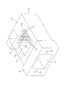
【解決手段】 フェルール11自体は、二次元配列の光ファイバ穴15に対応する光ファイバガイド溝を持たない。多心光ファイバの各光ファイバを光ファイバ穴15に挿入する際、下面に光ファイバガイド溝21aを持つ光ファイバ挿入治具21を接着剤充填窓13aから中空部13に挿入する。ガイド溝21aを案内として最下段の横1列の光ファイバ穴15に光ファイバを挿入する。以下順次、光ファイバ挿入治具21を1段ずつ上方に移動させながら、ガイド溝21aを案内として光ファイバを光ファイバ穴15に挿入していく。光ファイバ穴の段数が増しても、中空部13の形状が複雑にならない。フェルールの樹脂成形が容易、光ファイバ挿入作業も容易、光ファイバ誤挿入の問題も生じない。
【選択図】 図1PROBLEM TO BE SOLVED: To provide a ferrule for a two-dimensional array type optical connector which does not cause a problem even if the number of stages of two-dimensional array optical fiber holes is increased.
A ferrule 11 itself does not have an optical fiber guide groove corresponding to a two-dimensional array of optical fiber holes 15. When each optical fiber of the multi-core optical fiber is inserted into the optical fiber hole 15, an optical fiber insertion jig 21 having an optical fiber guide groove 21a on the lower surface is inserted into the hollow portion 13 from the adhesive filling window 13a. Using the guide groove 21a as a guide, the optical fiber is inserted into the optical fiber hole 15 in the lowermost horizontal row. Subsequently, the optical fiber is inserted into the optical fiber hole 15 using the guide groove 21a as a guide while sequentially moving the optical fiber insertion jig 21 step by step. Even if the number of optical fiber holes increases, the shape of the hollow portion 13 does not become complicated. Ferrule resin molding is easy, optical fiber insertion work is easy, and there is no problem of erroneous optical fiber insertion.
[Selection] Figure 1
Description
この発明は、二次元配列型光コネクタ用フェルールにおける多段の光ファイバ穴に光ファイバを挿入する技術に関し、二次元配列型光コネクタ用フェルール、及びその光ファイバ穴への光ファイバ挿入方法、及びこれに用いる光ファイバ挿入治具に関する。 The present invention relates to a technique for inserting an optical fiber into a multi-stage optical fiber hole in a ferrule for a two-dimensional array optical connector, a ferrule for a two-dimensional array optical connector, an optical fiber insertion method into the optical fiber hole, and the same The present invention relates to an optical fiber insertion jig used in the above.
多数の光ファイバの一括接続を可能にする光コネクタとして、嵌合ピン位置決め方式で二次元配列型の光コネクタが知られている。この二次元配列型光コネクタは、二次元配列型のフェルール、すなわち横1列の光ファイバ穴を多段に設けたフェルールを用いる。
図10〜図12にこの種の従来の二次元配列型光コネクタ用フェルール1を示す。この二次元配列型光コネクタ用フェルール(以下、フェルールという)1は、多心光ファイバを挿入するフェルール後端側(図10〜図12で左側)の筒状開口部2の前方(図10〜図12で右方)に、上面に接着剤充填窓3a持つ中空部3を形成し、この中空部3の前方壁面3bからフェルール先端面(光接続端面)4に貫通する二次元配列の複数の光ファイバ穴5をあけ、前記光ファイバ穴5と平行な2つのピン嵌合穴6を設けた構成である。このフェルール1は、相手側のフェルールとそれぞれのピン嵌入穴6に嵌入した共通の嵌合ピンで相互の位置決めを行なう位置決め方式であり、光ファイバ穴5が多段に設けられていることを除けば、一般にMT光コネクタと称されているもので、JIS C 5981に規定されるF12形多心光ファイバコネクタ用のフェルールに概ね相当する。
2. Description of the Related Art A two-dimensional array type optical connector with a fitting pin positioning method is known as an optical connector that enables a large number of optical fibers to be connected together. This two-dimensional array type optical connector uses a two-dimensional array type ferrule, that is, a ferrule provided with a plurality of horizontal rows of optical fiber holes.
10 to 12 show such a conventional two-dimensional array type
図示のフェルール1は、横1列の8つの光ファイバ穴5を2段に設けたものであるが、この種の従来の二次元配列型のフェルール1では、図示のように、各段の光ファイバ穴5にそれぞれ対応して光ファイバガイド溝7が階段状に設けられている。光ファイバ穴5に光ファイバを挿入する際、光ファイバを光ファイバガイド溝(以下、単にガイド溝という)7を案内として光ファイバ穴5に挿入する。
The illustrated
各光ファイバ穴5に対応してガイド溝7を設けること自体は、通常の一次元配列のMTフェルールの場合と同じであるが、光ファイバ穴5の配列が図示例のような2段等の少ない段数であれば二次元配列であっても特に問題はないとしても、光ファイバ穴5が多段化すると問題が生じる。すなわち、光ファイバ穴の段数が多くなると、エポキシ樹脂等の樹脂成形品であるフェルールの中空部内に多段のガイド溝を設けることが、樹脂成形上困難になる。
また、上段になるほどガイド溝の長さが短くなり、光ファイバ穴への光ファイバの挿入作業が困難になる。
また、多段化に伴い、光ファイバを別の光ファイバ穴に挿入してしまう光ファイバ誤挿入の可能性も増える。
Providing the guide groove 7 corresponding to each
In addition, the guide groove becomes shorter as it goes up, making it difficult to insert the optical fiber into the optical fiber hole.
As the number of stages increases, the possibility of erroneous insertion of an optical fiber that inserts the optical fiber into another optical fiber hole increases.
本発明は上記従来の欠点を解消するためになされたもので、フェルールの成形が容易であり、光ファイバ挿入作業も容易であり、また光ファイバ誤挿入の問題も生じない二次元配列型光コネクタ用フェルール、及び、その光ファイバ穴への光ファイバ挿入方法、及びこれに用いる光ファイバ挿入治具を提供することを目的とする。 The present invention has been made in order to eliminate the above-described conventional drawbacks, and is a two-dimensional array type optical connector that is easy to form a ferrule, easy to insert an optical fiber, and does not cause a problem of erroneous optical fiber insertion. An object of the present invention is to provide an optical ferrule, a method for inserting an optical fiber into the optical fiber hole, and an optical fiber insertion jig used therefor.
上記課題を解決する請求項1の発明は、多心光ファイバを挿入するフェルール後端側の筒状開口部の前方に、上面に接着剤充填窓を持つ中空部を形成し、この中空部の前方壁面からフェルール先端面に貫通する二次元配列の複数の光ファイバ穴をあけ、前記光ファイバ穴と平行な2つのピン嵌合穴を設けた嵌合ピン位置決め方式の二次元配列型光コネクタ用フェルールにおいて、
前記二次元配列の複数の光ファイバ穴が開口する中空部の前方壁面が光ファイバ穴長手方向と直角な面一の垂直面であることを特徴とする。
In the invention of
The front wall surface of the hollow portion where the plurality of optical fiber holes of the two-dimensional array are opened is a vertical surface that is perpendicular to the longitudinal direction of the optical fiber hole.
請求項2の発明は、請求項1の二次元配列型光コネクタ用フェルールに多心光ファイバを取り付ける際に、二次元配列の複数の光ファイバ穴にそれぞれ光ファイバを挿入する光ファイバ挿入方法であって、
横1列の各光ファイバ穴にそれぞれ対応する複数の光ファイバガイド溝を下面側に備えた光ファイバ挿入治具を前記接着剤充填窓から中空部に挿入し、この光ファイバ挿入治具を最下段の光ファイバ穴列に対応する位置に保持し、その光ファイバガイド溝を案内として光ファイバを最下段の光ファイバ穴に挿入し、以下順次、光ファイバ挿入治具を上方に1段ずつ垂直に移動させながら、その光ファイバガイド溝を案内として光ファイバを光ファイバ穴に挿入していくことを特徴とする。
The invention of
An optical fiber insertion jig provided with a plurality of optical fiber guide grooves respectively corresponding to each of the optical fiber holes in the horizontal row is inserted into the hollow portion from the adhesive filling window, and the optical fiber insertion jig is Hold at the position corresponding to the lower row of optical fiber holes, insert the optical fiber into the lowermost optical fiber hole using the optical fiber guide groove as a guide, and then vertically step by step the optical fiber insertion jig one by one upward The optical fiber is inserted into the optical fiber hole using the optical fiber guide groove as a guide.
請求項3の発明は、請求項1の二次元配列型光コネクタ用フェルールに多心光ファイバを取り付ける際に、二次元配列の複数の光ファイバ穴にそれぞれ光ファイバを挿入するための光ファイバ挿入治具であって、
接着剤充填窓下方の中空部内で垂直に上下移動可能であるとともに、横1列の各光ファイバ穴にそれぞれ対応する複数の光ファイバガイド溝を下面側に備えたことを特徴とする。
According to a third aspect of the present invention, when a multi-core optical fiber is attached to the two-dimensional array type optical connector ferrule of the first aspect, the optical fiber is inserted into each of the plurality of optical fiber holes of the two-dimensional array. A jig,
The optical fiber guide groove is vertically movable in a hollow portion below the adhesive filling window, and has a plurality of optical fiber guide grooves corresponding to each of the optical fiber holes in one horizontal row on the lower surface side.
請求項4は、請求項3記載の光ファイバ挿入治具が可視光を透過する材料からなることを特徴とする。 According to a fourth aspect of the present invention, the optical fiber insertion jig according to the third aspect is made of a material that transmits visible light.
本発明によれば、フェルール自体には光ファイバガイド溝がなく、フェルールの中空部の前方壁面が面一の単なる垂直面なので、二次元配列の光ファイバ穴の段数が多くなっても、内部形状が複雑にならず単純なままであり、樹脂成形品であるフェルールを成形する金型構造が簡略化され、成形が容易になる
また、光ファイバの案内に用いる光ファイバガイド溝は、上下に移動させて用いる別部材(光ファイバ挿入治具)に設けたものであるから、光ファイバ穴の段位置によらず常に同じ光ファイバガイド溝を用いるので、従来のものと異なり、上段になるほどガイド溝の長さが短くなって光ファイバ挿入作業が困難になるという問題は生じない。
また、光ファイバ穴の段数が多くなっても、光ファイバ挿入作業の際には、光ファイバ挿入治具の横1列の光ファイバガイド溝だけを用いるので、光ファイバを別の光ファイバ穴に挿入してしまう光ファイバ誤挿入の恐れはない。
According to the present invention, the ferrule itself does not have an optical fiber guide groove, and the front wall surface of the ferrule hollow portion is a simple vertical surface, so that the internal shape can be increased even if the number of optical fiber holes in the two-dimensional array increases. However, the mold structure for molding the ferrule, which is a resin molded product, is simplified and molding is easy. The optical fiber guide groove used for guiding the optical fiber moves up and down. Since the same optical fiber guide groove is always used regardless of the step position of the optical fiber hole, unlike the conventional one, the guide groove becomes higher at the upper stage. There is no problem that the length of the optical fiber becomes short and the optical fiber insertion work becomes difficult.
Even if the number of optical fiber holes increases, only one horizontal optical fiber guide groove of the optical fiber insertion jig is used during the optical fiber insertion work. There is no risk of erroneous insertion of an optical fiber.
請求項4のように、光ファイバ挿入治具の材料に可視光を透過する材料を用いると、光ファイバを光ファイバガイド溝で案内して光ファイバ穴に挿入する作業を、接着剤充填窓の上方から目で見ながら行なえるので、光ファイバ挿入の作業性が向上する。 When a material that transmits visible light is used as the material of the optical fiber insertion jig, the operation of guiding the optical fiber through the optical fiber guide groove and inserting it into the optical fiber hole is performed by the adhesive filling window. Since this can be done while viewing from above, the workability of optical fiber insertion is improved.
以下、本発明を実施した二次元配列型光コネクタ用フェルール、及び、その光ファイバ穴への光ファイバ挿入方法、及びこれに用いる光ファイバ挿入治具について、図面を参照して説明する。 Hereinafter, a ferrule for a two-dimensional array type optical connector, a method for inserting an optical fiber into an optical fiber hole, and an optical fiber insertion jig used therefor will be described with reference to the drawings.
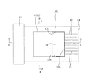
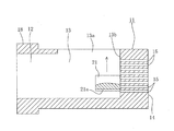
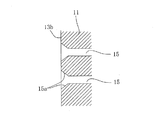
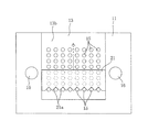
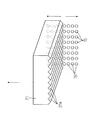
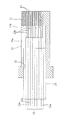
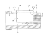
図1は本発明の一実施例の二次元配列型光コネクタ用フェルール(以下、場合により光コネクタ用フェルール、あるいは単にフェルールという)11の斜視図、図2は図1の光コネクタ用フェルール11の平面図、図3は図2のA−A断面図、図5は図2のB−B断面図である。これらの図に示すように、この光コネクタ用フェルール11は、多心光ファイバを挿入するフェルール後端側(図1〜図3等で左側)の筒状開口部12の前方(図1〜図3等で右方)に、上面に接着剤充填窓13a持つ中空部13を形成し、この中空部13の前方壁面13bに当該前方壁面13bからフェルール先端面(光接続端面)14に貫通する二次元配列の複数の光ファイバ穴15をあけ、前記光ファイバ穴15と平行な2つのピン嵌合穴16を設けた構成である。また、フェルール後端側に鍔部18を形成している。このフェルール11は、相手側のフェルールとそれぞれのピン嵌入穴16に嵌入した共通の嵌合ピンで相互の位置決めを行なう位置決め方式であり、光ファイバ穴15が多段に設けられていることを除けば、一般にMT光コネクタと称されているもので、JIS C 5981に規定されるF12形多心光ファイバコネクタ用のフェルールに概ね相当する。
FIG. 1 is a perspective view of a ferrule for a two-dimensional array type optical connector (hereinafter sometimes referred to as an optical connector ferrule or simply a ferrule) 11 according to an embodiment of the present invention, and FIG. 2 is an
本発明では、図示の通り、上記二次元配列の複数の光ファイバ穴15が開口する中空部13の前方壁面13bが、光ファイバ長手方向と直角な面一の垂直面である。すなわち、図示のフェルール11は、横1列の8つの光ファイバ穴15を8段に設けたものであるが、これらの各光ファイバ穴15が1つの垂直面(前方壁面13b)に格子状配列であけられ、それぞれフェルール先端面14に貫通している。なお、図4に拡大して示すように、光ファイバ穴15の入口部には、光ファイバを挿入し易いように、テーパ状に広がった案内面15aを形成している。
In the present invention, as shown in the drawing, the
上記の二次元配列型のフェルール11に多心光ファイバを取り付けるに際して、多心光ファイバの個々の光ファイバを二次元配列の光ファイバ穴15に挿入するが、その際、図1〜図3、図6等に示すごとき光ファイバ挿入治具21を用いて行なう。この光ファイバ挿入治具21は、接着剤充填窓13aの下方の中空部13内で垂直に上下移動可能であるとともに、横1列の各光ファイバ穴15にそれぞれ対応する複数の光ファイバガイド溝21aを下面側に備えている。
When attaching a multi-core optical fiber to the above-described two-dimensional
多心光ファイバの光ファイバを上記の二次元配列の光ファイバ穴15に挿入する場合、光ファイバ挿入治具21を接着剤充填窓13aから中空部13に挿入し、図3に示すように、前方壁面13bに当てた状態で最下段の光ファイバ穴15列に対応する高さ位置に保持する。この状態で光ファイバを光ファイバガイド溝21aに沿ってスライドさせて最下段の光ファイバ穴15に挿入する。次いで、光ファイバ挿入治具21を1段だけ上に移動させて保持し、その状態で光ファイバをその段の光ファイバ穴15に挿入する。以下順次、光ファイバ挿入治具21を上方に1段ずつ垂直に移動させながら、その光ファイバガイド溝21aを案内として光ファイバを光ファイバ穴15に挿入していく。光ファイバ挿入治具21は、上下移動に際して中空部13の前方壁面13b及び左右の側壁面13cにガイドされて垂直に上下移動できる。
When inserting an optical fiber of a multi-core optical fiber into the two-dimensional array of
上記の光ファイバ挿入方法によれば、各段毎に光ファイバガイド溝を階段状に設けた従来構造と異なり、二次元配列の光ファイバ穴15の段数が多くなっても、フェルール11の内部形状が複雑にならず単純なままであり、樹脂成形品であるフェルール11を成形する金型構造が簡略化され、成形が容易になる。
また、光ファイバの案内に用いる光ファイバガイド溝21aは、上下に移動させて用いる別部材(光ファイバ挿入治具21)に設けたものであるから、光ファイバ穴の段位置によらず常に同じ光ファイバガイド溝21aを用いるので、従来のものと異なり、上段になるほどガイド溝の長さが短くなって光ファイバ挿入作業が困難になるという問題は生じない。
また、光ファイバ穴の段数が多くなっても、光ファイバ挿入作業の際には、光ファイバ挿入治具21の横1列の光ファイバガイド溝21aだけを用いるので、光ファイバを別の光ファイバ穴に挿入してしまう光ファイバ誤挿入の恐れはない。
なお、光ファイバ挿入治具21を、可視光を透過する材料(ガラスあるいは樹脂)で構成すれば、光ファイバを光ファイバガイド溝21aに沿ってスライドさせて光ファイバ穴15に挿入する作業を接着剤充填窓13aの上方から目で見ながら行なえるので、光ファイバ挿入の作業性が向上する。
According to the above-described optical fiber insertion method, unlike the conventional structure in which the optical fiber guide grooves are provided in steps in each step, the internal shape of the
Further, since the optical
Even if the number of optical fiber holes increases, only one horizontal optical
If the optical
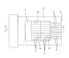
図7にこの二次元配列型のフェルール11に多心光ファイバ22を取り付けた状態を示す。図示例の多心光ファイバ22は横8本×8段の合計64本の光ファイバ22aからなる。各光ファイバ22aの被覆を除去した裸ファイバ22bが光ファイバ穴15に挿入固定される。
なお、本発明において多心光ファイバとは、二次元配列型のフェルール11に取り付けられる複数の光ファイバ22aの全体を意味するもので、種々の場合がある。すなわち、複数の単心光ファイバが単に集まったものである場合がある。また、複数の光ファイバテープ心線が複数段に配されたものである場合がある。また、全部の光ファイバが共通の被覆で覆われて1本の多心光ファイバ心線(ないし多心光ファイバコード)となっている場合がある。この場合は、少なくとも各段毎に分離してから、フェルール11に取り付ける。なお、図7では多心光ファイバ22の筒状開口部12の部分にブーツ23を被せた場合として示しているが、この部分の構造は任意である。なお、裸ファイバを光ファイバ穴15に挿入固定した後、接着剤を接着剤充填窓13aから中空部13に充填して光ファイバの被覆部をフェルール11に固定する。
FIG. 7 shows a state in which the multi-core
In the present invention, the multi-core optical fiber means the whole of the plurality of
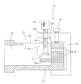
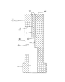
上記の光ファイバ挿入治具21の垂直に上下移動させる手段は任意であり、光ファイバ挿入治具21の形状ないし構造によっては手作業でもよいが、図8に光ファイバ挿入治具21を垂直に上下移動させる光ファイバ挿入治具上下移動機構31の一例を示す。この光ファイバ挿入治具上下移動機構31は、セットボルト32でフェルール11に固定した概ねコ字形の枠33の延出部に雌ねじ33aを形成し、こ雌ねじ33aに、光ファイバ挿入治具21の上面に回転のみ可能に垂直に連結したねじ軸34を螺合させた構造である。
ねじ軸34のつまみ34aを回してねじ軸34を上下に移動させ、これと一体に光ファイバ挿入治具21を上下移動させる。その際、光ファイバ挿入治具21は中空部13の前方壁面13b及び左右の側壁面13cに案内されて垂直に上下移動できる。
The means for vertically moving the optical
The
図9に光ファイバ挿入治具21’の他の実施例を示す。この実施例の光ファイバ挿入治具21’は、上面から見た形状を例えば接着剤充填窓13aの形状に合わせて、中空部13の前方壁面13bに接触する面21’bと中空部13の後方壁面13dに接触する面21’cとを持つ形状にしたものである。この構成によれば、光ファイバ挿入治具21’を垂直に上下移動させることが容易である。
FIG. 9 shows another embodiment of the optical fiber insertion jig 21 '. The optical
本発明において、フェルールに設ける光ファイバ穴の数は任意であり、横1列の光ファイバ穴の数、段数も任意である。また、各段の光ファイバ穴の数は必ずしも同一でなくてもよい。
また、光ファイバ挿入治具の材料は透明材料に限らず、光ファイバガイド溝を精度よく形成するのに適した材料であれば、種々の材料を用いることができる。
In the present invention, the number of optical fiber holes provided in the ferrule is arbitrary, and the number of optical fiber holes in one horizontal row and the number of stages are also arbitrary. Further, the number of optical fiber holes in each stage is not necessarily the same.
The material of the optical fiber insertion jig is not limited to a transparent material, and various materials can be used as long as the material is suitable for accurately forming the optical fiber guide groove.
11 光コネクタ用フェルール(二次元配列型光コネクタ用フェルール)
12 筒状開口部
13 中空部
13a 接着剤充填窓
13b (中空部の)前方壁面
13c (中空部の)左右の側壁面
14 フェルール先端面
15 光ファイバ穴
15a 案内面
16 ピン嵌入穴
18 鍔部
21 光ファイバ挿入治具
21a 光ファイバガイド溝
22 多心光ファイバ
23 ブーツ
31 光ファイバ挿入治具上下移動機構
11 Ferrule for optical connector (ferrule for two-dimensional array type optical connector)
12
Claims (4)
前記二次元配列の複数の光ファイバ穴が開口する中空部の前方壁面が光ファイバ穴長手方向と直角な面一の垂直面であることを特徴とする二次元配列型光コネクタ用フェルール。 A two-dimensional array is formed in front of the cylindrical opening on the rear end side of the ferrule into which the multi-core optical fiber is inserted, and a hollow portion having an adhesive filling window is formed on the upper surface and penetrates from the front wall surface of the hollow portion to the ferrule tip surface. In the ferrule for a two-dimensional array type optical connector of a fitting pin positioning method in which a plurality of optical fiber holes are drilled and two pin fitting holes parallel to the optical fiber hole are provided.
A ferrule for a two-dimensional array type optical connector, wherein a front wall surface of a hollow portion where a plurality of optical fiber holes of the two-dimensional array are opened is a vertical surface that is perpendicular to the longitudinal direction of the optical fiber hole.
横1列の各光ファイバ穴にそれぞれ対応する複数の光ファイバガイド溝を下面側に備えた光ファイバ挿入治具を前記接着剤充填窓から中空部に挿入し、この光ファイバ挿入治具を最下段の光ファイバ穴列に対応する位置に保持し、その光ファイバガイド溝を案内として光ファイバを最下段の光ファイバ穴に挿入し、以下順次、光ファイバ挿入治具を上方に1段ずつ垂直に移動させながら、その光ファイバガイド溝を案内として光ファイバを光ファイバ穴に挿入していくことを特徴とする光ファイバ挿入方法。 An optical fiber insertion method for inserting optical fibers into a plurality of optical fiber holes in a two-dimensional array when attaching a multi-core optical fiber to the ferrule for a two-dimensional array optical connector according to claim 1,
An optical fiber insertion jig provided with a plurality of optical fiber guide grooves respectively corresponding to each of the optical fiber holes in the horizontal row is inserted into the hollow portion from the adhesive filling window, and the optical fiber insertion jig is Hold at the position corresponding to the lower row of optical fiber holes, insert the optical fiber into the lowermost optical fiber hole using the optical fiber guide groove as a guide, and then vertically step by step the optical fiber insertion jig one by one upward And inserting the optical fiber into the optical fiber hole using the optical fiber guide groove as a guide.
接着剤充填窓下方の中空部内で垂直に上下移動可能であるとともに、横1列の各光ファイバ穴にそれぞれ対応する複数の光ファイバガイド溝を下面側に備えたことを特徴とする光ファイバ挿入治具。 An optical fiber insertion jig for inserting an optical fiber into each of a plurality of optical fiber holes in a two-dimensional array when attaching a multi-core optical fiber to the two-dimensional array type optical connector ferrule of claim 1,
Optical fiber insertion characterized in that it is vertically movable in the hollow portion below the adhesive filling window and has a plurality of optical fiber guide grooves corresponding to each of the optical fiber holes in one horizontal row on the lower surface side. jig.
4. The optical fiber insertion jig according to claim 3, wherein the optical fiber insertion jig is made of a material that transmits visible light.
Priority Applications (1)
| Application Number | Priority Date | Filing Date | Title |
|---|---|---|---|
| JP2003337874A JP4124457B2 (en) | 2003-09-29 | 2003-09-29 | Optical fiber insertion method and optical fiber insertion jig for optical fiber hole of ferrule for two-dimensional array type optical connector |
Applications Claiming Priority (1)
| Application Number | Priority Date | Filing Date | Title |
|---|---|---|---|
| JP2003337874A JP4124457B2 (en) | 2003-09-29 | 2003-09-29 | Optical fiber insertion method and optical fiber insertion jig for optical fiber hole of ferrule for two-dimensional array type optical connector |
Publications (2)
| Publication Number | Publication Date |
|---|---|
| JP2005106984A true JP2005106984A (en) | 2005-04-21 |
| JP4124457B2 JP4124457B2 (en) | 2008-07-23 |
Family
ID=34533570
Family Applications (1)
| Application Number | Title | Priority Date | Filing Date |
|---|---|---|---|
| JP2003337874A Expired - Fee Related JP4124457B2 (en) | 2003-09-29 | 2003-09-29 | Optical fiber insertion method and optical fiber insertion jig for optical fiber hole of ferrule for two-dimensional array type optical connector |
Country Status (1)
| Country | Link |
|---|---|
| JP (1) | JP4124457B2 (en) |
Cited By (4)
| Publication number | Priority date | Publication date | Assignee | Title |
|---|---|---|---|---|
| WO2008146385A1 (en) * | 2007-05-31 | 2008-12-04 | Fujikura Ltd. | Optical path converting member, optical connector and optical apparatus |
| JP2011022620A (en) * | 2010-11-04 | 2011-02-03 | Fujikura Ltd | Optical fiber connector ferrule and connecting method using the same |
| US10579012B2 (en) | 2015-02-27 | 2020-03-03 | Canon Kabushiki Kaisha | Cartridge, process cartridge, and image forming apparatus |
| CN113189710A (en) * | 2021-04-15 | 2021-07-30 | 苏州安捷讯光电科技股份有限公司 | Multicore high-density low-loss connector core insert and connector |
-
2003
- 2003-09-29 JP JP2003337874A patent/JP4124457B2/en not_active Expired - Fee Related
Cited By (5)
| Publication number | Priority date | Publication date | Assignee | Title |
|---|---|---|---|---|
| WO2008146385A1 (en) * | 2007-05-31 | 2008-12-04 | Fujikura Ltd. | Optical path converting member, optical connector and optical apparatus |
| US8376633B2 (en) | 2007-05-31 | 2013-02-19 | Fujikara Ltd. | Optical path changer component, optical connector and optical device |
| JP2011022620A (en) * | 2010-11-04 | 2011-02-03 | Fujikura Ltd | Optical fiber connector ferrule and connecting method using the same |
| US10579012B2 (en) | 2015-02-27 | 2020-03-03 | Canon Kabushiki Kaisha | Cartridge, process cartridge, and image forming apparatus |
| CN113189710A (en) * | 2021-04-15 | 2021-07-30 | 苏州安捷讯光电科技股份有限公司 | Multicore high-density low-loss connector core insert and connector |
Also Published As
| Publication number | Publication date |
|---|---|
| JP4124457B2 (en) | 2008-07-23 |
Similar Documents
| Publication | Publication Date | Title |
|---|---|---|
| EP3088926B1 (en) | Optical connector ferrule with a boot | |
| US9684136B2 (en) | Fiber optic connector with ferrule boot | |
| US20110026882A1 (en) | Lensed optical connector with passive alignment features | |
| JP5290713B2 (en) | Bending connector structure and manufacturing method thereof | |
| EP2998770A1 (en) | Optical connector and manufacturing method for optical connector | |
| JP2019056920A (en) | Optical connector ferrule | |
| KR20060048214A (en) | Multicore Optical Connector Assembly | |
| JP4783129B2 (en) | Optical path changing member, optical connector and optical device | |
| JP4124457B2 (en) | Optical fiber insertion method and optical fiber insertion jig for optical fiber hole of ferrule for two-dimensional array type optical connector | |
| JP2009193030A (en) | Optical ferrule with optical fiber | |
| JP2009157143A (en) | Ferrule for multi-fiber optical connector | |
| AU638372B2 (en) | Mold die for manufacturing optical module and manufacturing method using the same | |
| JP2010128111A (en) | Low-loss optical fiber, optical fiber array, connector structure and method of manufacturing low-loss optical fiber | |
| JP4491721B2 (en) | Ferrule for optical connector | |
| JP5342678B2 (en) | connector | |
| US6811319B2 (en) | Optical connector | |
| JP5075562B2 (en) | Multi-fiber optical connector and assembly method thereof | |
| JP5065112B2 (en) | Ferrule for optical connector | |
| JPH1184177A (en) | Multi-core optical connector | |
| JPWO2018168141A1 (en) | Method for manufacturing optical connector ferrule, optical connector ferrule, and optical fiber with connector | |
| JP2004062100A (en) | Method of manufacturing ferrule for optical connector and ferrule for optical connector | |
| JP2009139608A (en) | Manufacturing method of multi-fiber optical connector with optical fiber | |
| JP7540070B2 (en) | Ferrule for optical connector, optical connector, and method for manufacturing optical connector | |
| JP5075968B2 (en) | Optical fiber connector ferrule and connection method using the same | |
| JP4550322B2 (en) | Optical connector ferrule and method for manufacturing the same, optical connector and method for assembling the same |
Legal Events
| Date | Code | Title | Description |
|---|---|---|---|
| A621 | Written request for application examination |
Free format text: JAPANESE INTERMEDIATE CODE: A621 Effective date: 20060620 |
|
| A977 | Report on retrieval |
Free format text: JAPANESE INTERMEDIATE CODE: A971007 Effective date: 20080125 |
|
| A131 | Notification of reasons for refusal |
Free format text: JAPANESE INTERMEDIATE CODE: A131 Effective date: 20080201 |
|
| A521 | Written amendment |
Free format text: JAPANESE INTERMEDIATE CODE: A523 Effective date: 20080331 |
|
| TRDD | Decision of grant or rejection written | ||
| A01 | Written decision to grant a patent or to grant a registration (utility model) |
Free format text: JAPANESE INTERMEDIATE CODE: A01 Effective date: 20080501 |
|
| A01 | Written decision to grant a patent or to grant a registration (utility model) |
Free format text: JAPANESE INTERMEDIATE CODE: A01 |
|
| A61 | First payment of annual fees (during grant procedure) |
Free format text: JAPANESE INTERMEDIATE CODE: A61 Effective date: 20080501 |
|
| FPAY | Renewal fee payment (prs date is renewal date of database) |
Free format text: PAYMENT UNTIL: 20110516 Year of fee payment: 3 |
|
| FPAY | Renewal fee payment (prs date is renewal date of database) |
Free format text: PAYMENT UNTIL: 20110516 Year of fee payment: 3 |
|
| FPAY | Renewal fee payment (prs date is renewal date of database) |
Free format text: PAYMENT UNTIL: 20120516 Year of fee payment: 4 |
|
| FPAY | Renewal fee payment (prs date is renewal date of database) |
Free format text: PAYMENT UNTIL: 20130516 Year of fee payment: 5 |
|
| FPAY | Renewal fee payment (prs date is renewal date of database) |
Free format text: PAYMENT UNTIL: 20140516 Year of fee payment: 6 |
|
| LAPS | Cancellation because of no payment of annual fees |