JP2005084049A - Method and system for tracking target optically - Google Patents
Method and system for tracking target optically Download PDFInfo
- Publication number
- JP2005084049A JP2005084049A JP2004244725A JP2004244725A JP2005084049A JP 2005084049 A JP2005084049 A JP 2005084049A JP 2004244725 A JP2004244725 A JP 2004244725A JP 2004244725 A JP2004244725 A JP 2004244725A JP 2005084049 A JP2005084049 A JP 2005084049A
- Authority
- JP
- Japan
- Prior art keywords
- light beam
- target
- steering device
- tracking system
- beam steering
- Prior art date
- Legal status (The legal status is an assumption and is not a legal conclusion. Google has not performed a legal analysis and makes no representation as to the accuracy of the status listed.)
- Pending
Links
Images


Classifications
-
- G—PHYSICS
- G06—COMPUTING; CALCULATING OR COUNTING
- G06F—ELECTRIC DIGITAL DATA PROCESSING
- G06F3/00—Input arrangements for transferring data to be processed into a form capable of being handled by the computer; Output arrangements for transferring data from processing unit to output unit, e.g. interface arrangements
- G06F3/01—Input arrangements or combined input and output arrangements for interaction between user and computer
- G06F3/03—Arrangements for converting the position or the displacement of a member into a coded form
- G06F3/041—Digitisers, e.g. for touch screens or touch pads, characterised by the transducing means
- G06F3/042—Digitisers, e.g. for touch screens or touch pads, characterised by the transducing means by opto-electronic means
- G06F3/0421—Digitisers, e.g. for touch screens or touch pads, characterised by the transducing means by opto-electronic means by interrupting or reflecting a light beam, e.g. optical touch-screen
- G06F3/0423—Digitisers, e.g. for touch screens or touch pads, characterised by the transducing means by opto-electronic means by interrupting or reflecting a light beam, e.g. optical touch-screen using sweeping light beams, e.g. using rotating or vibrating mirror
-
- G—PHYSICS
- G01—MEASURING; TESTING
- G01S—RADIO DIRECTION-FINDING; RADIO NAVIGATION; DETERMINING DISTANCE OR VELOCITY BY USE OF RADIO WAVES; LOCATING OR PRESENCE-DETECTING BY USE OF THE REFLECTION OR RERADIATION OF RADIO WAVES; ANALOGOUS ARRANGEMENTS USING OTHER WAVES
- G01S17/00—Systems using the reflection or reradiation of electromagnetic waves other than radio waves, e.g. lidar systems
- G01S17/02—Systems using the reflection of electromagnetic waves other than radio waves
- G01S17/06—Systems determining position data of a target
- G01S17/46—Indirect determination of position data
- G01S17/48—Active triangulation systems, i.e. using the transmission and reflection of electromagnetic waves other than radio waves
-
- G—PHYSICS
- G01—MEASURING; TESTING
- G01S—RADIO DIRECTION-FINDING; RADIO NAVIGATION; DETERMINING DISTANCE OR VELOCITY BY USE OF RADIO WAVES; LOCATING OR PRESENCE-DETECTING BY USE OF THE REFLECTION OR RERADIATION OF RADIO WAVES; ANALOGOUS ARRANGEMENTS USING OTHER WAVES
- G01S17/00—Systems using the reflection or reradiation of electromagnetic waves other than radio waves, e.g. lidar systems
- G01S17/66—Tracking systems using electromagnetic waves other than radio waves
-
- G—PHYSICS
- G01—MEASURING; TESTING
- G01S—RADIO DIRECTION-FINDING; RADIO NAVIGATION; DETERMINING DISTANCE OR VELOCITY BY USE OF RADIO WAVES; LOCATING OR PRESENCE-DETECTING BY USE OF THE REFLECTION OR RERADIATION OF RADIO WAVES; ANALOGOUS ARRANGEMENTS USING OTHER WAVES
- G01S17/00—Systems using the reflection or reradiation of electromagnetic waves other than radio waves, e.g. lidar systems
- G01S17/88—Lidar systems specially adapted for specific applications
Abstract
Description
本発明は、一般に、光学システムに関するものである。更に詳しくは、本発明は、三角測量法を使用するターゲットの光学的な追跡に関するものである。 The present invention relates generally to optical systems. More particularly, the present invention relates to optical tracking of a target using triangulation.
コンピュータシステムに対するデータ入力を実現すると共に、コンピュータシステムを操作するためのナビゲーション/カーソル制御を実現するベく、様々なシステム及び装置が開発されている。これらのシステム及び装置における進歩は、コンピュータシステムの使用の急激な拡大に関連するものである。 Various systems and devices have been developed to provide data input to a computer system and to provide navigation / cursor control for operating the computer system. Advances in these systems and devices are associated with the rapid expansion of the use of computer systems.
これらのシステム及び装置においては、通常、いくつかの技術の中の1つが利用されている。これらの技術の例には、機械式のトラックボール、加速度検出、光学的な画像相関、レーザースペックルパターン分析、及び強度検出が含まれるが、その他の技術も使用されている。 In these systems and devices, typically one of several techniques is utilized. Examples of these techniques include mechanical trackball, acceleration detection, optical image correlation, laser speckle pattern analysis, and intensity detection, although other techniques are used.
これらのシステム及び装置における改善により、コンピュータシステムの有用性は向上しているが、これらのシステム及び装置が実装する技術に伴ういくつかの欠点のために、これらのシステム及び装置の潜在的な利点が制限された状態が続いている。例えば、限定的な分解能しか有していない技術により、コンピュータシステムの使用が妨げられている。又、これらの技術の中には、応答時間が遅いものも存在する。そして、その他の技術は、特定のタイプの表面上でしか使用することができない。又、特定の技術においては、電力消費の問題が発生する。そして、最後に、これらの技術の中には、実装するためにシステム及び装置に必要とされるサイズが不都合なものも存在するのである。 Although improvements in these systems and devices have increased the usefulness of computer systems, the potential benefits of these systems and devices are due to several drawbacks associated with the technology that these systems and devices implement. Continues to be restricted. For example, technology that has only limited resolution prevents the use of computer systems. Some of these techniques have a slow response time. And other techniques can only be used on certain types of surfaces. Also, with certain technologies, there is a problem of power consumption. And finally, some of these technologies have inconvenient sizes required for systems and devices to implement.
これらの欠点以外に、これらの既存の技術には、その他の問題も関連している。即ち、通常、これら既存の技術は、2次元のナビゲーション/カーソル制御と相対的な座標追跡(例:位置の変化)に限定されている。物体の絶対的な位置(例:現在の位置)ではなく、物体の位置の変化を2次元の空間において追跡しているのである。この相対座標追跡により、絶対位置の追跡が必要とされる手書き入力などのアプリケーションにおいて、これらのシステム及び装置の有用性は制限されている。要すれば、既存の技術は、克服することが困難な重大な制限を有しているのである。 Besides these drawbacks, other problems are also associated with these existing technologies. That is, these existing techniques are typically limited to two-dimensional navigation / cursor control and relative coordinate tracking (eg, position change). Instead of tracking the absolute position of the object (eg, the current position), the change in the position of the object is tracked in a two-dimensional space. This relative coordinate tracking limits the usefulness of these systems and devices in applications such as handwriting input where absolute position tracking is required. In short, existing technology has serious limitations that are difficult to overcome.
三角測量法を使用してターゲットを光学的に追跡する方法及びシステムが開示される。光学式位置追跡システムは、第1光ビームを第1角度範囲内で掃引し、ターゲットによる第1光ビームの反射を発生させる第1光ビームステアリング(steering)装置を有している。更には、この光学式位置追跡システムは、第2光ビームを第2角度範囲内で掃引し、ターゲットによる第2光ビームの反射を発生させる第2光ビームステアリング装置をも有している。又、この光学式位置追跡システムは、第1光ビームの第1角度値および第2光ビームの第2角度値を利用した三角測量法によるターゲットの位置の判定を実現する。これら第1角度値及び第2角度値は、個々の反射の存在に依存するものである。 A method and system for optically tracking a target using triangulation is disclosed. The optical position tracking system includes a first light beam steering device that sweeps the first light beam within a first angular range and generates a reflection of the first light beam by the target. The optical position tracking system further includes a second light beam steering device that sweeps the second light beam within a second angular range and causes the second light beam to be reflected by the target. The optical position tracking system also realizes target position determination by triangulation using the first angle value of the first light beam and the second angle value of the second light beam. These first and second angle values depend on the presence of individual reflections.
本明細書に包含され、その一部を形成する以下の添付図面は、本発明による実施例を例示しており、本明細書の記述内容と協働して、本発明による実施例の原理を説明するべく機能するものである。 The following accompanying drawings, which are incorporated in and constitute a part of this specification, illustrate an embodiment of the invention and, in cooperation with the description herein, illustrate the principles of the embodiment of the invention. It functions to explain.
以下、本発明による実施例を詳細に参照するが、これらの例は、添付の図面に示されているとおりである。尚、これらの実施例との関連で、本発明について説明するが、これは、本発明をこれらの実施例に限定することを意図するものはないことを理解されたい。むしろ、本発明は、添付の請求項によって定義されている本発明の理念と範囲内に含まれる代替物、変更物、及び等価物をも含むことを意図するものである。又、本発明による実施例に関する以下の詳細な説明においては、本発明を十分に理解できるように、多数の特定の詳細項目について記述している。 Reference will now be made in detail to embodiments of the present invention, examples of which are illustrated in the accompanying drawings. While the present invention will be described in connection with these examples, it should be understood that it is not intended to limit the invention to these examples. On the contrary, the invention is intended to cover alternatives, modifications and equivalents, which may be included within the spirit and scope of the invention as defined by the appended claims. Also, in the following detailed description of embodiments according to the present invention, numerous specific details are set forth in order to provide a thorough understanding of the present invention.
本発明による実施例において、光学式位置追跡システムは、第1光ビームと第2光ビームを生成する光ビーム生成器を有している。この光学式位置追跡システムは、第1光ビームを第1角度範囲内で掃引し、第1光ビームがターゲットによって反射された際に、この第1光ビームの反射を第1検出器にガイドする第1光ビームステアリング装置を更に含んでいる。この第1光ビームの反射は、第1反射光ビームから構成されている。更に、この光学式位置追跡システムは、第2光ビームを第2角度範囲内で掃引し、第2光ビームがターゲットによって反射された際に、この第2光ビームの反射を第2検出器にガイドする第2光ビームステアリング装置を更に含んでいる。この第2光ビームの反射は、第2反射光ビームから構成されている。第1及び第2光ビームステアリング装置は、第1距離だけ離隔している。更に、この光学式位置追跡システムは、ターゲットが第1光ビームを反射した際の第1光ビームの第1角度値、ターゲットが第2光ビームを反射した際の第2光ビームの第2角度値、及び第1距離を含むデータ、並びに三角測量法を使用してターゲットの位置を判定する処理ユニットを更に有している。 In an embodiment according to the invention, the optical position tracking system comprises a light beam generator for generating a first light beam and a second light beam. The optical position tracking system sweeps the first light beam within a first angular range and guides the reflection of the first light beam to the first detector when the first light beam is reflected by the target. A first light beam steering device is further included. The reflection of the first light beam is composed of the first reflected light beam. Furthermore, the optical position tracking system sweeps the second light beam within a second angular range, and reflects the second light beam to the second detector when the second light beam is reflected by the target. A second light beam steering device for guiding is further included. The reflection of the second light beam is composed of the second reflected light beam. The first and second light beam steering devices are separated by a first distance. The optical position tracking system further includes a first angle value of the first light beam when the target reflects the first light beam, and a second angle of the second light beam when the target reflects the second light beam. A processing unit is further included for determining the position of the target using the data including the value and the first distance, and triangulation.
構造
図1を参照すれば、本発明による実施例のシステム100が図示されており、光学式位置追跡システム20が示されている。又、図2を参照すれば、本発明による実施例のターゲット205の絶対位置を追跡する光学式位置追跡システム200の図が示されている。以下の説明においては、まず、本発明による実施例の物理的な構造について説明する。そして、その後に、本発明による実施例の動作について説明することとする。
Referring to structure diagram 1, which is the
本発明による実施例の物理的な構造に関連し、図1は、本発明による実施例のシステム100を示しており、光学式位置追跡システム20が示されている。このシステム100は、コンピュータシステム50と光学式位置追跡システム20を含んでいる。そして、コンピュータシステム50は、ディスプレイ60を有している。
In relation to the physical structure of an embodiment according to the present invention, FIG. 1 shows an
本発明によるこの実施例においては、光学式位置追跡システム20は、ターゲット10が2次元空間において移動した際に、ターゲット10の位置を追跡する。具体的には、位置追跡システム20は、2次元空間内において、角度範囲95内で掃引される少なくとも1つの光ビーム90を利用する。この光ビーム90が動作する2次元空間内において、ターゲット10が、左、右、前、後、又はこれらを組み合わせた方向に移動すると、光ビーム90が、ターゲットによって反射されることになる。この光ビーム90の反射は、反射光ビーム80から構成されており、位置追跡システム20は、これを受光及び処理してターゲット10の位置を追跡する。
In this embodiment according to the present invention, the optical
このターゲット10は、どのようなタイプの物体であってもよい。例えば、ターゲット10は、マウスタイプの装置、ペン、タッチスクリーン入力タイプの装置、指、及びこれらに類似のものであってよい。このターゲット10の再帰反射表面(retro-reflecting surface)により、ターゲット10の移動を追跡する光学式位置追跡システム20の能力が向上する。尚、ターゲット10が十分な反射特性を有している場合には、再帰反射表面は、必ずしも必要ではない。
This
ターゲット10の位置に対応する位置データを生成することによって光学式位置追跡システム20が追跡するターゲット10の動きを利用し、コンピュータシステム50にデータを入力したり(例:手書き入力)、ディスプレイ60上にナビゲートしたり、或いは、コンピュータシステム50のカーソルを制御することができる。
By generating position data corresponding to the position of the
本発明による別の実施例においては、光学式位置追跡システム20をディスプレイ60と統合し、ターゲット10がディスプレイ60の表面上を移動する際に、タッチスクリーン機能を提供している。この実装は、従来技術によるタッチスクリーンの実装に比べて、安価且つ簡単である。
In another embodiment according to the present invention, the optical
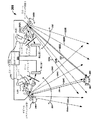
図2は、本発明による実施例のターゲット205の絶対位置を追跡する光学式位置追跡システム200を示している。図2に示されているように、光学式位置追跡システム200は、光ビーム生成器210、光ビームステアリング装置1、光ビームステアリング装置2、検出器1、検出器2、及び処理ユニット220を有している。又、光学式位置追跡システム200は、ビームスプリッタ1及びビームスプリッタ2も含んでいる。要約すれば、検出器1及び検出器2との関連で、光ビームステアリング装置1と光ビームステアリング装置2に対するターゲット205の角度関係を判定するのである。既に、光ビームステアリング装置1の位置、光ビームステアリング装置2の位置、及び光ビームステアリング装置1と光ビームステアリング装置2間の離隔距離は判明している。従って、この情報を使用し、三角測量演算を実行して、ターゲット205の絶対位置を得ることができる。
FIG. 2 illustrates an optical
光ビーム生成器210は、第1光ビーム224と第2光ビーム222を生成する。光ビームステアリング装置1によって実行される第1光ビーム224の掃引動作を示すべく、図2には、様々な角度位置における第1光ビーム224が示されている(例:224A〜224E)。同様に、光ビームステアリング装置2によって実行される第2光ビーム222の掃引動作を示すべく、図2には、様々な角度位置における第2光ビーム222が示されている(例:222A〜222E)。
The light beam generator 210 generates a first light beam 224 and a second light beam 222. In order to show the sweep operation of the first light beam 224 executed by the light
継続して図2を参照すれば、光ビーム生成器210は、第1光ビーム224を生成する光源1と第2光ビーム222を生成する光源2を含んでいる。又、光ビーム生成器210は、コリメーティングレンズ1及びコリメーティングレンズ2をも有している。本発明による別の実施例においては、光ビーム生成器210は、1つの光ビームを供給する1つの光源を有しており、この光ビームを分割して第1光ビーム224と第2光ビーム222を生成することができる。
With continued reference to FIG. 2, the light beam generator 210 includes a
本発明による一実施例においては、光源(例:光源1及び光源2)は、低コストのLED(発光ダイオード)技術に基づいたものであってよい。本発明による別の実施例においては、光源は、VCSEL(垂直共振器面発光レーザー)技術に基づいたものであってよい。本発明に基づいた更に別の実施例においては、光源は、適切なコリメーティング能力を有する低コストの白熱技術に基づいたものであってよい。本発明による更に別の実施例においては、光源は、高出力の希土類に基づいたレーザーによるものであってよい。希土類に基づいたレーザーの例には、Nd−YAG(Neodymium Yttrium Aluminum Garnet、ネオジウム添加イットリウム・アルミニウム・ガーネット)レーザーやパルス化エルビウムレーザーが含まれる。高出力の希土類に基づいたレーザーは、ターゲット205と検出器間の距離又は吸収によって大きな光出力が必要とされる場合に、使用することができる。
In one embodiment according to the present invention, the light sources (eg,
光ビームステアリング装置1は、第1光ビーム224を角度範囲230内で掃引する。又、ターゲット205及び光ビームステアリング装置1に対する第1光ビーム224の角度の追跡も行う。これについては、図3に示されており、後程詳述する。光ビームステアリング装置2は、第2光ビーム222を角度範囲232内で掃引する。更に、ターゲット205及び光ビームステアリング装置2に対する第2光ビーム222の角度の追跡も行う。これについては、図3に示されており、後程詳述する。
The light
ここで、光ビームステアリング装置1と光ビームステアリング装置2は、どのようなタイプの光ビームステアリング装置であってもよい。本発明による一実施例においては、光ビームステアリング装置は、MEMS(Micro Electro Mechanical System、微細電気機械システム)モータービームステアリング装置である。本発明による別の実施例においては、光ビームステアリング装置は、検流計ビームステアリング装置である。本発明による更に別の実施例においては、光ビームステアリング装置は、音響光学的な(acousto-optic)ビームステアリング装置である。本発明の更に別の実施例においては、光ビームステアリング装置は、電気光学的な(electro-optic)ビームステアリング装置である。本発明による更に別の実施例においては、光ビームステアリング装置は、格子構造のビームステアリング装置である。本発明による別の実施例においては、光ビームステアリング装置は、ホログラフィ構造のビームステアリング装置である。本発明による別の実施例においては、光ビームステアリング装置は、走査ミラービームステアリング装置である。MEMS処理により、大幅な費用及びサイズの節約を実現することができる。
Here, the light
図2に示されているように、ターゲット205は、第1光ビーム224及び第2光ビーム222を反射する再帰反射表面207を含んでいる。この「再帰反射(retro-reflecting)」という用語は、入射光ビームに対して平行な方向に入射光ビームが反射する特性を意味している。この再帰反射表面207は、再帰反射テープ、再帰反射塗料、又はターゲット205の表面に結合したその他の再帰反射材料などの方式によって実装することができる。前述のように、ターゲット205は、どのようなタイプの物体であってもよい。例えば、ターゲット205は、マウスタイプの装置、ペン、タッチスクリーン入力タイプの装置、指、及びこれらに類似のものであってよい。尚、ターゲット205が十分な反射特性を有しており、ターゲット205が、入射光ビームに対して平行に入射光ビームを反射する場合には、再帰反射表面は、必ずしも必要ではない。一例として、再帰反射表面を筆記側端部に有する事務用ペンの動きを追跡し、コンピュータシステムのカーソル制御として使用することが可能である。
As shown in FIG. 2, the
本発明による一実施例においては、検出器1は、フォトダイオードであり、検出器2も、フォトダイオードである。これら検出器1及び検出器2は、本発明によるその他の実施例において、別の方式によって実装することができる。
In one embodiment according to the present invention, the
又、光ビームステアリング装置1、検出器1、光ビームステアリング装置2、及び検出器2には、処理ユニット220が接続されている。処理ユニット220は、様々なデータと三角測量法を使用して、ターゲット205の位置を判定する。本発明による一実施例においては、ターゲット205の絶対位置が判定される。
A
動作
次に、本節においては、本発明による実施例の動作について詳細に説明する。
Operation Next, in this section, the operation of the embodiment according to the present invention will be described in detail.
図2を参照すれば、光学式位置追跡システム200の動作は、以下のように進行する。即ち、まず、光源1が第1光ビーム224を生成する。この第1光ビーム224は、コリメーティングレンズ1を通過し、この結果、第1光ビーム224は平行化される。コリメーティングレンズ1の後に、第1光ビーム224は、ビームスプリッタ1に向かって伝播し、このビームスプリッタによって、光ビームステアリング装置1にガイドされる。そして、光ビームステアリング装置1が、第1光ビーム224を角度範囲230内で掃引し、この結果、第1光ビーム224が様々な角度位置(例:224A〜224E)に表れることになる。ここで、矢印240A及び240Bは、第1光ビーム224を角度範囲230内で掃引するべく動作する光ビームステアリング装置1を示している。
Referring to FIG. 2, the operation of the optical
同様に、光源2が第2光ビーム222を生成する。この第2光ビーム222は、コリメーティングレンズ2を通過し、この結果、第2光ビーム222は平行化される。コリメーティングレンズ2の後に、第2光ビーム222は、ビームスプリッタ2に向かって伝播し、このビームスプリッタによって、光ビームステアリング装置2にガイドされる。そして、光ビームステアリング装置2が、第2光ビーム222を角度範囲232内で掃引し、この結果、第2光ビーム222が様々な角度位置(例:222A〜222E)に表れることになる。ここで、矢印242A及び242Bは、第2光ビーム222を角度範囲232内で掃引するべく動作する光ビームステアリング装置2を示している。図2に示されているように、光ビームステアリング装置1及び光ビームステアリング装置2は、同時に、個々の角度範囲において、個々の光ビームをステアリングする。
Similarly, the
ターゲット205の再帰反射表面207により、第1光ビーム244(例:224C)が反射されると、この第1光ビーム224Cの反射は、光ビームステアリング装置1に向かって反射することになる。この第1光ビーム224Cの反射は、第1反射光ビーム225から構成されている。光ビームステアリング装置1は、この第1反射光ビーム225をビームスプリッタ1及び検出器1にガイドする。そして、検出器1が、第1反射光ビーム225を検出し、処理ユニット220に対して、ターゲット205が検出されたことを通知し、この結果、処理ユニット220が、第1光ビーム224Cの現在の角度(例:図3の角度A)を記録することになる。本発明による一実施例においては、処理ユニット220は、光ビームステアリング装置1によって掃引される第1光ビーム224の角度を追跡する。
When the first light beam 244 (for example, 224C) is reflected by the
一方、ターゲット205の再帰反射表面207により、第2光ビーム222(例:222C)が反射されると、この第2光ビーム222Cの反射は、光ビームステアリング装置2に向かって反射することになる。この第2光ビーム222Cの反射は、第2反射光ビーム223から構成されている。光ビームステアリング装置2は、この第2反射光ビーム223をビームスプリッタ2及び検出器2にガイドする。そして、検出器2が、第2反射光ビーム223を検出し、処理ユニット220に対して、ターゲット205が検出されたことを通知し、この結果、処理ユニット220が、第2光ビーム222Cの現在の角度(例:図3の角度B)を記録することになる。本発明による一実施例においては、処理ユニット220は、光ビームステアリング装置2によって掃引される第2光ビーム222の角度を追跡する。
On the other hand, when the second light beam 222 (for example, 222C) is reflected by the
更に、処理ユニット220が、前述のデータと図3に示されている三角測量法を使用してターゲット205の絶対位置を判定する。具体的には、図3は、本発明による実施例の図2の光学式位置追跡システム200によって判定されるターゲット205の絶対位置Tを示している。この図3に示されているように、光ビームステアリング装置1の位置P1、光ビームステアリング装置2の位置P2、及び光ビームステアリング装置1と光ビームステアリング装置2間の離隔距離Mは、既に判明している。角度Aは、第1光ビーム224がターゲット205によって反射し、検出器1に第1反射光ビーム225を検出させた角度に対応している。又、角度Bは、第2光ビーム222がターゲット205によって反射し、検出器2に第2反射光ビーム223を検出させた角度に対応している。前述のように、この第1光ビーム224と第2光ビーム222の角度値を追跡する。この結果、これらのデータと三角測量法により、ターゲット205の絶対位置Tを判定することが可能であり、この三角測量においては、三角関数の使用が必要となる。
In addition, the
尚、図1及び図2には、一対の光ビームステアリング装置による2次元のターゲット追跡が示されているが、本発明による実施例を拡張し、第3の次元に沿う光ビームステアリング装置を包含することにより、3次元のターゲット追跡を実現することも可能であることを理解されたい。 1 and FIG. 2 show two-dimensional target tracking by a pair of light beam steering devices, the embodiment according to the present invention is extended to include a light beam steering device along the third dimension. By doing so, it should be understood that three-dimensional target tracking can also be achieved.
この光学式位置追跡システム200によれば、多数の利点が提供される。即ち、ターゲットの絶対位置データを提供しつつ、ターゲットの動きを2次元又は3次元において追跡することができる。従来技術による相対位置追跡システムにおいては、ターゲットの新しい位置の判定は、ターゲットの以前の位置に依存している。従って、従来技術の相対位置追跡システムの場合には、ターゲットが追跡不能な方式で移動すると(例:表面からマウスを持ち上げる)、ターゲットが追跡可能な方式で再度移動するまで、新しい位置を判定することができない。これに対し、光学式位置追跡システム200の光ビーム掃引空間において、ターゲットが手書き方式において移動した場合には、以前の位置に関係なく、絶対位置データにより、ターゲットの現在の位置を通知し、コンピュータシステムに対する手書き入力を円滑に実行することができる。そして、ターゲットが、光学式位置追跡システム200の光ビーム掃引空間の範囲から離脱した場合にも(例:ターゲットを光ビーム掃引空間の上方に持ち上げる)、ターゲットが光学式位置追跡システム200の光ビーム掃引空間の範囲内に入ったときに、即座にターゲットの絶対位置を判定することができる。
The optical
更に、光学式位置追跡システム200によれば、ターゲットの特定の表面タイプに限定されることなしに、高分解能によるターゲットの追跡を提供することができる。例えば、従来技術の機械式トラックボールマウスでは、適切に動作するために滑らかな表面が必要であり、従来技術による光学式マウスの場合には、純粋な白の表面における問題点を有している。一方、光学式位置追跡システム200の動作は、ターゲットに対して受動的なものであり、制約は存在しない。この光学式位置追跡システム200によれば、小型であって、低コストで、低電力消費の実装が可能である。又、光学式位置追跡システム200は、容易に拡張することができる。図2に示されているコンポーネントの数は、近距離アプリケーション又は長距離アプリケーションのいずれにおいても、ターゲットの移動を追跡するのに十分なものである。但し、これらのアプリケーションにおけるこれらのコンポーネントの機能要件は異なるものになろう。
Furthermore, the optical
図4Aは、本発明による実施例の光ビームの円形断面400Aを示している。この円形断面400Aを有する光ビームは、光学式位置追跡システム200(図2)において利用することができる。円形断面400Aが小さいほど、光学式位置追跡システム200(図2)の分解能は大きくなる。
FIG. 4A shows a
図4Bは、本発明による実施例の光ビームの楕円形断面400Bを示している。この楕円形断面400Bを有する光ビームを光学式位置追跡システム200(図2)において利用することにより、ターゲット205が光ビームステアリング装置の掃引方向に対して垂直に移動した場合に、ある程度の追跡公差を提供することができる。楕円形断面400Bは、掃引方向に垂直に延長しているため、光学式位置追跡システム200(図2)の追跡範囲を掃引方向に対して垂直に延長することができる。
FIG. 4B shows an
図5は、本発明による実施例の限定掃引モード(limited sweeping mode)において動作する図2の光学式位置追跡システム200を示している。図2の場合には、光ビームステアリング装置1及び光ビームステアリング装置2は、全角度範囲230及び全角度範囲232において、それぞれ掃引しているが、この図5においては、光ビームステアリング装置1と光ビームステアリング装置2は、限定された角度範囲250と限定された角度範囲252において、それぞれ掃引している。この限定掃引モードによれば、ターゲット205の検出速度を向上させる共に、分解能を向上させることができる。
FIG. 5 illustrates the optical
実際には、光ビームステアリング装置1と光ビームステアリング装置2は、当初、全体掃引モード(full sweeping mode)(例:全角度範囲230と全角度範囲232)において動作する。しかしながら、一旦、光ビームステアリング装置1に対する第1角度及び光ビームステアリング装置2に対する第2角度においてターゲット205を検出すると、光ビームステアリング装置1は、限定された角度範囲250である第1角度の周辺を掃引し、この結果、第1光ビーム224は、様々な角度位置(例:224A〜224C)に表れることになる。同様に、光ビームステアリング装置2は、限定された角度範囲252である第2角度の周辺を掃引し、この結果、第2光ビーム222が、様々な角度位置(例:222A〜222C)に表れることになる。ターゲット205の動きが短時間に大幅に変化しないと予測される場合には、この光ビームステアリング装置1及び光ビームステアリング装置2によるディザリング(dithering)動作により、大きな利点が提供される。尚、光ビームステアリング装置1及び光ビームステアリング装置2は、ターゲット205が限定掃引モードにおいて個々の光ビームを反射しなくなった場合に、全体掃引モードの動作に復帰する。
In practice, the light
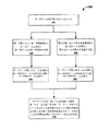
図6は、本発明による実施例のターゲットを光学的に追跡する方法600を示すフローチャートを示している。
FIG. 6 shows a flowchart illustrating a
まず、ステップ610において、第1光ビーム及び第2光ビームを生成する。次いで、本発明による一実施例においては、ステップ620及びステップ640をステップ630及びステップ650と同時に実行する。 First, in step 610, a first light beam and a second light beam are generated. Then, in one embodiment according to the present invention, step 620 and step 640 are performed simultaneously with step 630 and step 650.
即ち、ステップ620において、第1光ビームステアリング装置により、第1光ビームを第1位置における第1角度範囲において掃引する。そして、この第1光ビームの第1角度値を判定し追跡する。第1光ビームを第1角度範囲において掃引し、ターゲットによる第1光ビームの反射を発生させるのである。そして、ステップ640において、ターゲットが第1光ビームを反射し第1反射光ビームが生成された際に、この第1反射光ビームを検出する。 That is, in step 620, the first light beam is swept in the first angular range at the first position by the first light beam steering device. Then, the first angle value of the first light beam is determined and tracked. The first light beam is swept in the first angle range, and the reflection of the first light beam by the target is generated. In step 640, the first reflected light beam is detected when the target reflects the first light beam and the first reflected light beam is generated.
同様に、ステップ630において、第2光ビームステアリング装置により、第2光ビームを第2位置における第2角度範囲において掃引する。そして、第2光ビームの第2角度値を判定し追跡する。第2光ビームを第2角度範囲において掃引し、ターゲットによる第2光ビームの反射を発生させるのである。そして、ステップ650において、ターゲットが第2光ビームを反射し第2反射光ビームが生成された際に、第2反射光ビームを検出する。 Similarly, in step 630, the second light beam is swept in the second angle range at the second position by the second light beam steering device. Then, the second angle value of the second light beam is determined and tracked. The second light beam is swept in the second angle range, and the reflection of the second light beam by the target is generated. In step 650, the second reflected light beam is detected when the target reflects the second light beam and the second reflected light beam is generated.
ステップ660において、ターゲットによって第1及び第2光ビームが反射された際に、ターゲットの絶対位置を判定することができる。データを利用した三角測量法を使用する。即ち、ターゲットが第1光ビームを反射した際の第1光ビームの第1角度値、ターゲットが第2光ビームを反射した際の第2光ビームの第2角度値、及び第1及び第2位置間の距離などのデータを使用するのである。 In step 660, the absolute position of the target can be determined when the first and second light beams are reflected by the target. Use data triangulation method. That is, the first angle value of the first light beam when the target reflects the first light beam, the second angle value of the second light beam when the target reflects the second light beam, and the first and second Data such as the distance between positions is used.
本発明による特定の実施例に関する以上の説明は、例示と説明を目的として提示したものである。これらは、本発明のすべてを網羅したり、或いは、開示した態様そのままに本発明を限定することを意図するものではなく、以上の開示内容に鑑み、多くの変更及び変形が可能である。これらの実施例は、本発明の原理とその実際的なアプリケーションを十分に説明することにより、本発明と、想定される特定の使用法に適した様々な変更を有する様々な実施例を当業者が十分に利用できるようにするべく、選択及び説明したものである。従って、本発明の範囲は、添付の請求項及びその等価物に定義されているとおりである。 The foregoing descriptions of specific embodiments according to the present invention have been presented for purposes of illustration and description. They are not intended to be exhaustive or to limit the present invention to the disclosed aspects as they are, and many modifications and variations are possible in light of the above disclosure. These examples are provided to fully illustrate the principles of the invention and its practical application, and various examples having various modifications suitable for the invention and the particular use envisaged will be apparent to those skilled in the art. Is selected and explained in order to be fully usable. Accordingly, the scope of the invention is as defined in the appended claims and their equivalents.
50 コンピュータシステム
200 光学式位置追跡システム
205 ターゲット
207 再帰反射表面
220 処理ユニット
222 第2光ビーム
223 第2光ビームの反射
224 第1光ビーム
225 第1光ビームの反射
230 第1角度範囲
232 第2角度範囲
250 制限された角度範囲
252 制限された角度範囲
50
Claims (10)
第1角度範囲内で第1光ビームを掃引し、ターゲットによる前記第1光ビームの反射を発生させる第1光ビームステアリング装置と、
第2角度範囲内で第2光ビームを掃引し、前記ターゲットによる前記第2光ビームの反射を発生させる第2光ビームステアリング装置と、
を有し、
前記ターゲットの位置は、前記第1光ビームの第1角度値および前記第2光ビームの第2角度値を利用する三角測量法により求められ、前記第1角度値および前記第2角度値は、前記個々の反射の存在に依存する、
光学式位置追跡システム。 An optical position tracking system,
A first light beam steering device that sweeps the first light beam within a first angular range and causes the target to reflect the first light beam;
A second light beam steering device that sweeps a second light beam within a second angular range and causes the reflection of the second light beam by the target;
Have
The position of the target is obtained by triangulation using a first angle value of the first light beam and a second angle value of the second light beam, and the first angle value and the second angle value are: Depends on the presence of said individual reflections,
Optical position tracking system.
第2角度範囲内で第2光ビームを掃引し、前記ターゲットによる前記第2光ビームの反射を発生させる第2光ビームステアリング装置であって、前記ターゲットの位置は、前記第1光ビームの第1角度値および前記第2光ビームの第2角度値を利用する三角測量法により求められ、前記第1角度値および前記第2角度値は、前記個々の反射の存在に依存している、第2光ビームステアリング装置と、
前記ターゲットの前記位置を受信し使用するコンピュータシステムと、
を有するシステム。 A first light beam steering device that sweeps the first light beam within a first angular range and causes the target to reflect the first light beam;
A second light beam steering device that sweeps a second light beam within a second angle range and causes the second light beam to be reflected by the target, the position of the target being the second light beam of the first light beam. Determined by a triangulation method using one angle value and a second angle value of the second light beam, wherein the first angle value and the second angle value depend on the presence of the individual reflections, A two light beam steering device;
A computer system for receiving and using the location of the target;
Having a system.
第1位置において、第1角度範囲内で第1光ビームを掃引し、前記第1光ビームの第1角度値を求めるステップと、
第2位置において、第2角度範囲内で第2光ビームを掃引し、前記第2光ビームの第2角度値を求めるステップと、
前記ターゲットが前記第1及び第2光ビームを反射した際に、前記個々の反射の存在に依存する前記第1角度値及び第2角度値を利用する三角測量法により前記ターゲットの位置を求めるステップと、
を有する方法。
A method of optically tracking a target,
Sweeping the first light beam within a first angle range at a first position to determine a first angle value of the first light beam;
Sweeping the second light beam within a second angle range at a second position to determine a second angle value of the second light beam;
Determining the position of the target by triangulation using the first and second angle values depending on the presence of the individual reflections when the target reflects the first and second light beams; When,
Having a method.
Applications Claiming Priority (1)
| Application Number | Priority Date | Filing Date | Title |
|---|---|---|---|
| US10/655,944 US7359041B2 (en) | 2003-09-04 | 2003-09-04 | Method and system for optically tracking a target using a triangulation technique |
Publications (2)
| Publication Number | Publication Date |
|---|---|
| JP2005084049A true JP2005084049A (en) | 2005-03-31 |
| JP2005084049A5 JP2005084049A5 (en) | 2010-05-27 |
Family
ID=34136699
Family Applications (1)
| Application Number | Title | Priority Date | Filing Date |
|---|---|---|---|
| JP2004244725A Pending JP2005084049A (en) | 2003-09-04 | 2004-08-25 | Method and system for tracking target optically |
Country Status (4)
| Country | Link |
|---|---|
| US (1) | US7359041B2 (en) |
| EP (1) | EP1512989B1 (en) |
| JP (1) | JP2005084049A (en) |
| DE (1) | DE602004022900D1 (en) |
Cited By (4)
| Publication number | Priority date | Publication date | Assignee | Title |
|---|---|---|---|---|
| JP2007192755A (en) * | 2006-01-20 | 2007-08-02 | Fujitsu Ten Ltd | Range finder |
| WO2011136816A1 (en) * | 2010-04-30 | 2011-11-03 | Hewlett-Packard Development Company, L.P. | Determination of a sensor device location in a sensor network |
| JP2011237360A (en) * | 2010-05-13 | 2011-11-24 | Seiko Epson Corp | Optical type detection device, display device and electronic apparatus |
| JP2016201002A (en) * | 2015-04-10 | 2016-12-01 | 船井電機株式会社 | Position detector and space input device |
Families Citing this family (59)
| Publication number | Priority date | Publication date | Assignee | Title |
|---|---|---|---|---|
| US8729770B1 (en) | 2003-12-02 | 2014-05-20 | Adriatic Research Institute | MEMS actuators with combined force and bi-directional rotation |
| FR2872920B1 (en) * | 2004-07-06 | 2006-09-22 | Commissariat Energie Atomique | OPTICAL DEVICE FOR MEASURING THE SPEED OF MOVING A FIRST MOBILE ELEMENT IN RELATION TO A SECOND ELEMENT |
| EP2005282B1 (en) * | 2006-03-30 | 2013-01-30 | FlatFrog Laboratories AB | A system and a method of determining a position of a scattering/reflecting element on the surface of a radiation transmissive element |
| US8316324B2 (en) * | 2006-09-05 | 2012-11-20 | Navisense | Method and apparatus for touchless control of a device |
| US7508530B1 (en) * | 2007-03-08 | 2009-03-24 | Boxboro Systems, Llc | Multi-point position measuring and recording system for anthropomorphic test devices |
| EP2208354A4 (en) | 2007-10-10 | 2010-12-22 | Gerard Dirk Smits | Image projector with reflected light tracking |
| WO2009048365A1 (en) * | 2007-10-10 | 2009-04-16 | Flatfrog Laboratories Ab | A touch pad and a method of operating the touch pad |
| WO2009109058A1 (en) * | 2008-03-05 | 2009-09-11 | Quasmo Ag | Device and method for controlling the course of a game |
| CN201974159U (en) * | 2008-04-01 | 2011-09-14 | 感知器公司 | Contour sensor with MEMS reflector |
| US9170097B2 (en) | 2008-04-01 | 2015-10-27 | Perceptron, Inc. | Hybrid system |
| US9013711B2 (en) | 2008-04-01 | 2015-04-21 | Perceptron, Inc. | Contour sensor incorporating MEMS mirrors |
| US7924441B1 (en) * | 2008-08-08 | 2011-04-12 | Mirrorcle Technologies, Inc. | Fast and high-precision 3D tracking and position measurement with MEMS micromirrors |
| SE533704C2 (en) | 2008-12-05 | 2010-12-07 | Flatfrog Lab Ab | Touch sensitive apparatus and method for operating the same |
| TWI399676B (en) * | 2009-06-30 | 2013-06-21 | Pixart Imaging Inc | Object detection calibration system of an optical touch screen and method thereof |
| US8405639B1 (en) * | 2009-09-03 | 2013-03-26 | Advanced Numicro Systems, Inc. | Scanning mirror touch screen with minimum bezel height |
| WO2011109402A2 (en) | 2010-03-01 | 2011-09-09 | Gerard Dirk Smits | Safety device for scanned projector and illumination systems |
| US8416409B2 (en) * | 2010-06-04 | 2013-04-09 | Lockheed Martin Corporation | Method of ellipsometric reconnaissance |
| US9204129B2 (en) * | 2010-09-15 | 2015-12-01 | Perceptron, Inc. | Non-contact sensing system having MEMS-based light source |
| EP2625845B1 (en) | 2010-10-04 | 2021-03-03 | Gerard Dirk Smits | System and method for 3-d projection and enhancements for interactivity |
| GB201020282D0 (en) | 2010-11-30 | 2011-01-12 | Dev Ltd | An improved input device and associated method |
| TWI439905B (en) * | 2011-01-10 | 2014-06-01 | Young Lighting Technology Corp | Touch module and touch detecting method |
| US8723837B1 (en) * | 2011-04-05 | 2014-05-13 | Advanced Numicro Systems, Inc. | Scanning mirror touch screen |
| US8520219B2 (en) | 2011-12-19 | 2013-08-27 | Perceptron, Inc. | Non-contact sensor having improved laser spot |
| US10168835B2 (en) | 2012-05-23 | 2019-01-01 | Flatfrog Laboratories Ab | Spatial resolution in touch displays |
| GB2506106A (en) * | 2012-08-14 | 2014-03-26 | Light Blue Optics Ltd | Touch sensing systems using a pair of beam deflectors controlled in tandem |
| US8711370B1 (en) | 2012-10-04 | 2014-04-29 | Gerard Dirk Smits | Scanning optical positioning system with spatially triangulating receivers |
| US8971568B1 (en) | 2012-10-08 | 2015-03-03 | Gerard Dirk Smits | Method, apparatus, and manufacture for document writing and annotation with virtual ink |
| GB2515447B (en) * | 2013-02-13 | 2021-01-20 | Light Blue Optics Ltd | Touch sensing systems |
| US10019113B2 (en) | 2013-04-11 | 2018-07-10 | Flatfrog Laboratories Ab | Tomographic processing for touch detection |
| US9874978B2 (en) | 2013-07-12 | 2018-01-23 | Flatfrog Laboratories Ab | Partial detect mode |
| WO2015108479A1 (en) | 2014-01-16 | 2015-07-23 | Flatfrog Laboratories Ab | Light coupling in tir-based optical touch systems |
| US10126882B2 (en) | 2014-01-16 | 2018-11-13 | Flatfrog Laboratories Ab | TIR-based optical touch systems of projection-type |
| US9810913B2 (en) | 2014-03-28 | 2017-11-07 | Gerard Dirk Smits | Smart head-mounted projection system |
| US10161886B2 (en) | 2014-06-27 | 2018-12-25 | Flatfrog Laboratories Ab | Detection of surface contamination |
| WO2016025502A1 (en) * | 2014-08-11 | 2016-02-18 | Gerard Dirk Smits | Three-dimensional triangulation and time-of-flight based tracking systems and methods |
| US11182023B2 (en) | 2015-01-28 | 2021-11-23 | Flatfrog Laboratories Ab | Dynamic touch quarantine frames |
| US10318074B2 (en) | 2015-01-30 | 2019-06-11 | Flatfrog Laboratories Ab | Touch-sensing OLED display with tilted emitters |
| CN107209609A (en) | 2015-02-09 | 2017-09-26 | 平蛙实验室股份公司 | It is included in the optical touch system of the device of the projection of transmission panel above and within and detection light beam |
| WO2016140612A1 (en) | 2015-03-02 | 2016-09-09 | Flatfrog Laboratories Ab | Optical component for light coupling |
| US10043282B2 (en) | 2015-04-13 | 2018-08-07 | Gerard Dirk Smits | Machine vision for ego-motion, segmenting, and classifying objects |
| CN108369470B (en) | 2015-12-09 | 2022-02-08 | 平蛙实验室股份公司 | Improved stylus recognition |
| US9753126B2 (en) | 2015-12-18 | 2017-09-05 | Gerard Dirk Smits | Real time position sensing of objects |
| US9813673B2 (en) | 2016-01-20 | 2017-11-07 | Gerard Dirk Smits | Holographic video capture and telepresence system |
| WO2018106360A2 (en) | 2016-10-31 | 2018-06-14 | Gerard Dirk Smits | Fast scanning lidar with dynamic voxel probing |
| WO2018096430A1 (en) | 2016-11-24 | 2018-05-31 | Flatfrog Laboratories Ab | Automatic optimisation of touch signal |
| PT3667475T (en) | 2016-12-07 | 2022-10-17 | Flatfrog Lab Ab | A curved touch device |
| WO2018125850A1 (en) | 2016-12-27 | 2018-07-05 | Gerard Dirk Smits | Systems and methods for machine perception |
| US10963104B2 (en) | 2017-02-06 | 2021-03-30 | Flatfrog Laboratories Ab | Optical coupling in touch-sensing systems |
| US10481737B2 (en) | 2017-03-22 | 2019-11-19 | Flatfrog Laboratories Ab | Pen differentiation for touch display |
| CN110663015A (en) | 2017-03-28 | 2020-01-07 | 平蛙实验室股份公司 | Touch sensitive device and method for assembly |
| US10473921B2 (en) | 2017-05-10 | 2019-11-12 | Gerard Dirk Smits | Scan mirror systems and methods |
| CN117311543A (en) | 2017-09-01 | 2023-12-29 | 平蛙实验室股份公司 | Touch sensing device |
| US10591605B2 (en) | 2017-10-19 | 2020-03-17 | Gerard Dirk Smits | Methods and systems for navigating a vehicle including a novel fiducial marker system |
| US10379220B1 (en) | 2018-01-29 | 2019-08-13 | Gerard Dirk Smits | Hyper-resolved, high bandwidth scanned LIDAR systems |
| WO2019172826A1 (en) | 2018-03-05 | 2019-09-12 | Flatfrog Laboratories Ab | Improved touch-sensing apparatus |
| US10877154B2 (en) * | 2018-03-27 | 2020-12-29 | Intel Corporation | Range estimation for light detecting and ranging (LIDAR) systems |
| US11943563B2 (en) | 2019-01-25 | 2024-03-26 | FlatFrog Laboratories, AB | Videoconferencing terminal and method of operating the same |
| CN115039063A (en) | 2020-02-10 | 2022-09-09 | 平蛙实验室股份公司 | Improved touch sensing device |
| US11372320B2 (en) | 2020-02-27 | 2022-06-28 | Gerard Dirk Smits | High resolution scanning of remote objects with fast sweeping laser beams and signal recovery by twitchy pixel array |
Citations (9)
| Publication number | Priority date | Publication date | Assignee | Title |
|---|---|---|---|---|
| JPH03273419A (en) * | 1990-03-23 | 1991-12-04 | Wacom Co Ltd | Optical plural two-dimensional coordinate simultaneous input device |
| JPH04155204A (en) * | 1990-10-18 | 1992-05-28 | Yamaha Corp | Optical three-dimensional position detector |
| JPH04166715A (en) * | 1990-10-30 | 1992-06-12 | Topcon Corp | Surveying instrument |
| JPH0553717A (en) * | 1991-08-29 | 1993-03-05 | Wacom Co Ltd | Optical two-dimensional coordinate input device |
| JPH07104920A (en) * | 1993-10-05 | 1995-04-21 | Toppan Printing Co Ltd | Optical coordinate detector |
| JPH08150582A (en) * | 1994-11-28 | 1996-06-11 | Japan Aviation Electron Ind Ltd | Mobile robot travelling system |
| JP2001075645A (en) * | 1999-09-08 | 2001-03-23 | Hitachi Zosen Corp | Method and equipment for detecting position of mobing object |
| JP2001249762A (en) * | 2000-03-06 | 2001-09-14 | Ricoh Co Ltd | Coordinate inputting/detecting device and electronic blackboard system and position deviation correcting method for light receiving element and storage medium |
| JP2003122477A (en) * | 2001-10-16 | 2003-04-25 | Sony Corp | Input device and information processing device |
Family Cites Families (17)
| Publication number | Priority date | Publication date | Assignee | Title |
|---|---|---|---|---|
| US3613066A (en) * | 1968-10-22 | 1971-10-12 | Cii | Computer input equipment |
| DE2018799A1 (en) | 1970-04-20 | 1971-11-04 | Ver Flugtechnische Werke | Arrangement for the location and tracking of air targets. Note United Flugtechnische Werke-Fokker GmbH, 2800 Bremen |
| US4294543A (en) * | 1979-11-13 | 1981-10-13 | Command Control & Communications Corporation | Optical system for developing point coordinate information |
| US4654648A (en) * | 1984-12-17 | 1987-03-31 | Herrington Richard A | Wireless cursor control system |
| US4788441A (en) * | 1985-12-16 | 1988-11-29 | Acme-Cleveland Corporation | Range finder wherein distance between target and source is determined by measuring scan time across a retroreflective target |
| US4782328A (en) * | 1986-10-02 | 1988-11-01 | Product Development Services, Incorporated | Ambient-light-responsive touch screen data input method and system |
| DE68921543T2 (en) * | 1988-10-26 | 1995-07-20 | Wacom Co Ltd | Optical coordinate input device and position pointer therefor. |
| US5317140A (en) * | 1992-11-24 | 1994-05-31 | Dunthorn David I | Diffusion-assisted position location particularly for visual pen detection |
| US5525764A (en) * | 1994-06-09 | 1996-06-11 | Junkins; John L. | Laser scanning graphic input system |
| US5786804A (en) * | 1995-10-06 | 1998-07-28 | Hewlett-Packard Company | Method and system for tracking attitude |
| US6256016B1 (en) * | 1997-06-05 | 2001-07-03 | Logitech, Inc. | Optical detection system, device, and method utilizing optical matching |
| US6130663A (en) * | 1997-07-31 | 2000-10-10 | Null; Nathan D. | Touchless input method and apparatus |
| JP4033582B2 (en) * | 1998-06-09 | 2008-01-16 | 株式会社リコー | Coordinate input / detection device and electronic blackboard system |
| JP4040825B2 (en) * | 2000-06-12 | 2008-01-30 | 富士フイルム株式会社 | Image capturing apparatus and distance measuring method |
| FR2817339B1 (en) * | 2000-11-24 | 2004-05-14 | Mensi | THREE-DIMENSIONAL LIFTING DEVICE OF A LASER EMISSION SCENE |
| US6473167B1 (en) * | 2001-06-14 | 2002-10-29 | Ascension Technology Corporation | Position and orientation determination using stationary fan beam sources and rotating mirrors to sweep fan beams |
| US20030083844A1 (en) * | 2001-10-30 | 2003-05-01 | Reddi M. Mahadeva | Optical position sensing of multiple radiating sources in a movable body |
-
2003
- 2003-09-04 US US10/655,944 patent/US7359041B2/en not_active Expired - Fee Related
-
2004
- 2004-05-06 DE DE602004022900T patent/DE602004022900D1/en not_active Expired - Fee Related
- 2004-05-06 EP EP04010827A patent/EP1512989B1/en not_active Expired - Fee Related
- 2004-08-25 JP JP2004244725A patent/JP2005084049A/en active Pending
Patent Citations (9)
| Publication number | Priority date | Publication date | Assignee | Title |
|---|---|---|---|---|
| JPH03273419A (en) * | 1990-03-23 | 1991-12-04 | Wacom Co Ltd | Optical plural two-dimensional coordinate simultaneous input device |
| JPH04155204A (en) * | 1990-10-18 | 1992-05-28 | Yamaha Corp | Optical three-dimensional position detector |
| JPH04166715A (en) * | 1990-10-30 | 1992-06-12 | Topcon Corp | Surveying instrument |
| JPH0553717A (en) * | 1991-08-29 | 1993-03-05 | Wacom Co Ltd | Optical two-dimensional coordinate input device |
| JPH07104920A (en) * | 1993-10-05 | 1995-04-21 | Toppan Printing Co Ltd | Optical coordinate detector |
| JPH08150582A (en) * | 1994-11-28 | 1996-06-11 | Japan Aviation Electron Ind Ltd | Mobile robot travelling system |
| JP2001075645A (en) * | 1999-09-08 | 2001-03-23 | Hitachi Zosen Corp | Method and equipment for detecting position of mobing object |
| JP2001249762A (en) * | 2000-03-06 | 2001-09-14 | Ricoh Co Ltd | Coordinate inputting/detecting device and electronic blackboard system and position deviation correcting method for light receiving element and storage medium |
| JP2003122477A (en) * | 2001-10-16 | 2003-04-25 | Sony Corp | Input device and information processing device |
Cited By (5)
| Publication number | Priority date | Publication date | Assignee | Title |
|---|---|---|---|---|
| JP2007192755A (en) * | 2006-01-20 | 2007-08-02 | Fujitsu Ten Ltd | Range finder |
| WO2011136816A1 (en) * | 2010-04-30 | 2011-11-03 | Hewlett-Packard Development Company, L.P. | Determination of a sensor device location in a sensor network |
| US8913231B2 (en) | 2010-04-30 | 2014-12-16 | Hewlett-Packard Development Company, L.P. | Determination of a sensor device location in a sensor network |
| JP2011237360A (en) * | 2010-05-13 | 2011-11-24 | Seiko Epson Corp | Optical type detection device, display device and electronic apparatus |
| JP2016201002A (en) * | 2015-04-10 | 2016-12-01 | 船井電機株式会社 | Position detector and space input device |
Also Published As
| Publication number | Publication date |
|---|---|
| EP1512989A2 (en) | 2005-03-09 |
| EP1512989A3 (en) | 2006-03-08 |
| DE602004022900D1 (en) | 2009-10-15 |
| EP1512989B1 (en) | 2009-09-02 |
| US7359041B2 (en) | 2008-04-15 |
| US20050052635A1 (en) | 2005-03-10 |
Similar Documents
| Publication | Publication Date | Title |
|---|---|---|
| JP2005084049A (en) | Method and system for tracking target optically | |
| KR101097554B1 (en) | Method and system for optically tracking a target using an interferometric technique | |
| CA3024510C (en) | Multiple pixel scanning lidar | |
| US11255972B2 (en) | Actuated optical element for light beam scanning device | |
| EP3259615B1 (en) | Actuated optical element for light beam scanning device | |
| CA3057460A1 (en) | Lidar based 3-d imaging with structured light and integrated illumination and detection | |
| US20160320488A1 (en) | Solid-state electronic light detection and ranging (lidar) | |
| JP2000353048A (en) | Optical unit for detecting object, and position coordinate input device using the unit | |
| EP1706862A2 (en) | Position determination and motion tracking | |
| JP2005099009A (en) | Position determination method and apparatus responsive to retroreflective object | |
| EP3465249A1 (en) | Multiple pixel scanning lidar | |
| JP2013210956A (en) | Display device | |
| US11567210B2 (en) | LiDAR for vehicle blind spot detection | |
| JP2003337658A (en) | Light scanning touch panel | |
| JP2000089903A (en) | Optical scanning type touch panel | |
| TW200525433A (en) | Method and system for optically tracking a target using an interferometric technique | |
| JP2002163071A (en) | Photodetector | |
| JPH03192419A (en) | Optical two-dimensional coordinate input device and pen for inputting coordinate | |
| JP2023099238A (en) | Measurement device | |
| WO2000014623A1 (en) | Optical scanning touch panel | |
| JP2013003997A (en) | Optical position detector and display system with input function |
Legal Events
| Date | Code | Title | Description |
|---|---|---|---|
| A711 | Notification of change in applicant |
Free format text: JAPANESE INTERMEDIATE CODE: A711 Effective date: 20070326 |
|
| RD02 | Notification of acceptance of power of attorney |
Free format text: JAPANESE INTERMEDIATE CODE: A7422 Effective date: 20070410 |
|
| A621 | Written request for application examination |
Free format text: JAPANESE INTERMEDIATE CODE: A621 Effective date: 20070719 |
|
| RD03 | Notification of appointment of power of attorney |
Free format text: JAPANESE INTERMEDIATE CODE: A7423 Effective date: 20071114 |
|
| A521 | Written amendment |
Free format text: JAPANESE INTERMEDIATE CODE: A523 Effective date: 20100408 |
|
| A131 | Notification of reasons for refusal |
Free format text: JAPANESE INTERMEDIATE CODE: A131 Effective date: 20100629 |
|
| A521 | Written amendment |
Free format text: JAPANESE INTERMEDIATE CODE: A523 Effective date: 20100929 |
|
| A02 | Decision of refusal |
Free format text: JAPANESE INTERMEDIATE CODE: A02 Effective date: 20110308 |