JP2005074571A - Sheet material cutting apparatus - Google Patents
Sheet material cutting apparatus Download PDFInfo
- Publication number
- JP2005074571A JP2005074571A JP2003308367A JP2003308367A JP2005074571A JP 2005074571 A JP2005074571 A JP 2005074571A JP 2003308367 A JP2003308367 A JP 2003308367A JP 2003308367 A JP2003308367 A JP 2003308367A JP 2005074571 A JP2005074571 A JP 2005074571A
- Authority
- JP
- Japan
- Prior art keywords
- movable blade
- blade
- cutting edge
- fixed blade
- sheet material
- Prior art date
- Legal status (The legal status is an assumption and is not a legal conclusion. Google has not performed a legal analysis and makes no representation as to the accuracy of the status listed.)
- Pending
Links
Images


Landscapes
- Nonmetal Cutting Devices (AREA)
Abstract
Description
本発明は、プリンタや記録装置等に使用されるスライド式シート材切断装置に関するものである。 The present invention relates to a slide-type sheet material cutting device used for a printer, a recording device, and the like.
プリンタや記録装置等に使用されるシート材切断装置としては、直線刃先の固定刃にV字型に窪んだ刃先を有する可動刃を交差摺動させて切断するスライド式シート材切断装置が多く使用されている。 この方式のシート材切断装置では、可動刃は、その幅方向の両端からほぼ均等に固定刃に交差摺動し、且つ、可動刃がフレームから脱落しないように保持されている必要がある。
可動刃の姿勢を保持し、且つフレームから脱落しないための手段としては特開平9−155788号公報(特許文献1)のように可動刃両側面を保持するガイド部材を設けて姿勢を保持し、且つフレームの長孔に嵌挿されたスペーサを介在させて可動刃と座金とによりフレームを挟み込み、可動刃の貫通孔に挿通したビスとナットにより螺締し、座金、スペーサ、可動刃を一体に固定する方法や、特開2002−254386号公報(特許文献2)のようにフレーム長孔にスライダを嵌入し、可動刃とネジで挟み込む方法がある。
As a sheet material cutting device used for printers, recording devices, etc., many slide-type sheet material cutting devices are used which cut by moving a movable blade having a V-shaped recessed edge on a fixed blade with a straight edge. Has been. In the sheet material cutting apparatus of this system, the movable blade needs to be held so that the movable blade crosses the fixed blade almost evenly from both ends in the width direction and the movable blade does not fall off the frame.
As a means for maintaining the posture of the movable blade and preventing it from falling off the frame, a guide member for holding both sides of the movable blade is provided as in JP-A-9-155788 (Patent Document 1) to maintain the posture. In addition, the frame is sandwiched between the movable blade and the washer with the spacer inserted in the long hole of the frame, and screwed with the screw and nut inserted in the through hole of the movable blade, and the washer, spacer, and movable blade are integrated. There are a fixing method and a method of inserting a slider into a frame long hole and sandwiching it with a movable blade and a screw as disclosed in JP-A-2002-254386 (Patent Document 2).
また、可動刃を駆動させるためのモータ、ギヤ等の部品は、特開2001−54892号公報(特許文献3)図3や、特開平11−42589号公報(特許文献4)図1のようにフレームとは別の部材に配置した後にフレームと組み合わせる方法や特開平11−347986号公報(特許文献5)のようにフレームの中に可動刃等の部品といっしょに収納し、最後にカバーで蓋をする方法などが一般的である。
板状の可動刃と固定刃に対して該可動刃を切断動作方向に摺動させる駆動部とこれらを支持するフレームとを具備する可動刃部材と、固定刃を支持する固定刃部材とが、合体分離可能に配置され、合体位置で可動刃を固定刃に交差圧接かつ摺動させシート材を切断するシート材切断装置は、特開2001−347485公報(特許文献6)、特開2000−052291公報(特許文献7)等に紹介されている。分離しない構造の場合、プリンタにシート材をセットする時に固定刃と可動刃との間に設けた通紙用の窓にシート材を通す必要があるが、窓の高さは2mm程度と狭いため、シート材を通しにくいという不便さがあった。分離構造により固定刃部材と可動刃部材を分離した後、シート材をセットし、固定刃部材を再度合体させればセットが完了する。そのため用紙を狭い隙間に通す必要がなくなり、作業性がよくなるという効果がある。また、可動刃を板状とすることにより、プレス加工によって容易に成形することが可能であり、また、可動刃部材の厚さを薄くすることも可能であるため、コストダウンおよび小型化が可能となるという効果もある。
In addition, parts such as a motor and a gear for driving the movable blade are as shown in FIG. 3 of Japanese Patent Laid-Open No. 2001-54892 (Patent Document 3) and Japanese Patent Laid-Open No. 11-42589 (Patent Document 4) of FIG. After being placed on a member different from the frame, it is combined with the frame and stored in the frame together with parts such as a movable blade as disclosed in Japanese Patent Application Laid-Open No. 11-347986 (Patent Document 5). The method of doing is common.
A movable blade member comprising a plate-shaped movable blade and a drive unit that slides the movable blade in the cutting operation direction with respect to the fixed blade, and a frame that supports these, and a fixed blade member that supports the fixed blade, A sheet material cutting device which is arranged so as to be separable and which cuts a sheet material by cross-contacting and sliding the movable blade against the fixed blade at the merged position is disclosed in Japanese Patent Laid-Open Nos. 2001-347485 and 2000-052291. It is introduced in the gazette (patent document 7) etc. In the case of a structure that does not separate, it is necessary to pass the sheet material through a paper passing window provided between the fixed blade and the movable blade when setting the sheet material in the printer, but the height of the window is as narrow as about 2 mm. There was an inconvenience that it was difficult to pass the sheet material. After the fixed blade member and the movable blade member are separated by the separation structure, the sheet material is set, and the fixed blade member is combined again to complete the setting. Therefore, it is not necessary to pass the paper through a narrow gap, and the workability is improved. In addition, by making the movable blade into a plate shape, it can be easily formed by pressing, and the thickness of the movable blade member can also be reduced, thus reducing costs and downsizing. There is also an effect of becoming.
固定刃部材と可動刃部材が合体分離可能なシート材切断装置では、固定刃と可動刃を精度良く合体させることが困難であり、切断不具合の要因となっている。
例えば特許文献7には固定刃部材と可動刃部材が分離する構造が記載されているが、可動刃は、フレームに設けた軸にその一端をコイルバネで押し付けて保持されている。このような方法では可動刃は片持ちの状態であるため、刃先の位置が安定せず、固定刃との位置精度が確保しにくい。
本発明の目的は、可動刃と固定刃の位置精度を向上させ、安定な切断性能を確保できるシート材切断装置を提供することである。
In the sheet material cutting device in which the fixed blade member and the movable blade member can be separated and combined, it is difficult to accurately combine the fixed blade and the movable blade, which causes a cutting defect.
For example, Patent Document 7 describes a structure in which a fixed blade member and a movable blade member are separated, but the movable blade is held by pressing one end of the movable blade against a shaft provided on the frame with a coil spring. In such a method, since the movable blade is in a cantilever state, the position of the blade edge is not stable, and it is difficult to ensure the positional accuracy with the fixed blade.
The objective of this invention is providing the sheet | seat material cutting device which can improve the positional accuracy of a movable blade and a fixed blade, and can ensure the stable cutting performance.
上記目的を達成するために、本発明は、板状の可動刃と固定刃に対して該可動刃を切断動作方向に摺動させる駆動部とこれらを支持するフレームとを具備する可動刃部材と、固定刃を支持する固定刃部材とが、合体分離可能に配置され、合体位置で可動刃を固定刃に交差圧接かつ摺動させシート材を切断するシート材切断装置であって、前記可動刃部材の幅方向端部には、可動刃の幅方向位置及び固定刃への圧接方向位置を規制するガイドが設けられているシート材切断装置である。 In order to achieve the above object, the present invention provides a movable blade member comprising a plate-shaped movable blade, a drive unit that slides the movable blade in the cutting operation direction with respect to the fixed blade, and a frame that supports them. The fixed blade member that supports the fixed blade is arranged so as to be separable, and is a sheet material cutting device that cuts the sheet material by cross-contacting and sliding the movable blade against the fixed blade at the combined position, the movable blade The sheet material cutting device is provided with a guide for restricting the width direction position of the movable blade and the pressure contact direction position to the fixed blade at the end portion in the width direction of the member.
尚、前記可動刃は、V字型に窪んだ刃先線を有するものであることが望ましい。 The movable blade preferably has a cutting edge line that is recessed in a V shape.
また、前記可動刃の切断動作方向の両端は、突出するとともに、固定刃との圧接方向の反対方向に曲げられていることが望ましい。 In addition, it is desirable that both ends of the movable blade in the cutting operation direction protrude and bend in a direction opposite to the pressure contact direction with the fixed blade.
また、前記可動刃部材には、固定刃から受ける圧接力を可動刃を介して受ける可動刃受け部を有することが望ましい。 Further, it is desirable that the movable blade member has a movable blade receiving portion that receives a pressure contact force received from the fixed blade through the movable blade.
また、前記固定刃部材は、切断幅方向であって、かつ可動刃への圧接方向にあらかじめ反りを形成させていることが望ましい。 In addition, it is desirable that the fixed blade member be warped in advance in the cutting width direction and in the direction of pressure contact with the movable blade.
本発明によれば、前記可動刃部材の幅方向端部に可動刃の幅方向位置を規制するガイドが設けられているので、可動刃が傾いて、剪段角が変化したり、圧接力が変化したりして切断不良の要因となることが少ない。また、固定刃への圧接方向位置を規制するガイドも設けられているので、分離された固定刃部材が再び可動刃部材と合体した時に2部材の位置精度を一定に保つことが可能であり、可動刃と固定刃との交差、圧接状態を一定に保つことが可能となる。 According to the present invention, since the guide for regulating the width direction position of the movable blade is provided at the width direction end of the movable blade member, the movable blade is inclined, the cutting angle is changed, or the pressure contact force is reduced. It is less likely to cause cutting defects due to changes. In addition, since a guide for regulating the position in the pressure contact direction to the fixed blade is also provided, it is possible to keep the positional accuracy of the two members constant when the separated fixed blade member is combined with the movable blade member again, It is possible to keep the intersection between the movable blade and the fixed blade and the pressure contact state constant.
本発明において重要な特徴は、上述した合体可動刃部材の幅方向端部には、可動刃の幅方向位置及び固定刃への圧接方向位置を規制するガイドを設けたことにある。
本発明の合体分離可能なシート材切断装置は、可動刃と固定刃をいかに精度良く合体させるかが重要である。そのためには、可動刃の位置精度を出来るだけ高めることが重要である。そこで可動刃が切断方向に動作する過程で傾きを生じて剪断角が減少して切断できなくなることを防止するために幅方向の位置を規制し、さらに、固定刃部材と可動刃部材が合体した状態での厚さ方向の位置を安定させ、可動刃刃先が固定刃刃先と確実に交差、圧接を開始させるために固定刃への圧接方向の位置を規制するものとした。
本発明のガイドとしては、別部材で構成することも出来るが、例えば、幅方向両端をコの字形状に折り曲げ、可動刃と略同一幅としたフレームを用い、可動刃の幅方向端面をコの字の底相当部で規制すると共に、コの字の折り曲げ位置で固定刃への圧接方向位置を規制するといった方法を採用することができる。
このようなフレームは、金属材料でも良いが、成形の容易性から樹脂を用いても良い。
An important feature of the present invention is that a guide for regulating the width direction position of the movable blade and the pressure contact direction position to the fixed blade is provided at the end portion in the width direction of the combined movable blade member described above.
In the sheet material cutting device of the present invention that can be combined and separated, it is important to accurately combine the movable blade and the fixed blade. For that purpose, it is important to improve the position accuracy of the movable blade as much as possible. Therefore, the position in the width direction is regulated to prevent the movable blade from moving in the cutting direction so as to be inclined and the shear angle is reduced so that cutting cannot be performed, and the fixed blade member and the movable blade member are combined. In order to stabilize the position in the thickness direction in the state, the movable blade edge surely intersects the fixed blade edge, and starts the pressure contact, the position in the pressure contact direction to the fixed blade is regulated.
The guide of the present invention can be configured by a separate member, but for example, a frame having a substantially U-shaped frame bent at both ends in the width direction and having a width substantially the same as the movable blade is used. It is possible to adopt a method of restricting the position corresponding to the bottom of the U-shape and regulating the position in the pressure contact direction to the fixed blade at the position where the U-shape is bent.
Such a frame may be a metal material, but a resin may be used for ease of molding.
本発明では、前記可動刃は、V字型に窪んだ刃先線を有することが望ましい。その理由は、例えば、ギロチン式の可動刃、すなわち、可動刃の幅方向の片側から固定刃と交差、圧接して切断を開始し、中央部分を経過し、反対側で切断終了する構造のシート切断装置では、可動刃の切断開始側の刃先は固定刃に近く、切断終了側の刃先は固定刃から遠いため可動刃の形状は中央部を中心とした左右対称形状にはならない。そのため、フレームに設けたガイドと切断位置との位置関係は左右対称とならず、圧接力を一定に保持することが難しい。一方、V字型に窪んだ刃先線を有する可動刃の場合、可動刃のV字型の刃先と固定刃の直線刃先は、可動刃のV字の頂点を中心としてほぼ対称の2箇所で接するため、フレームに設けたガイド切断位置との関係は常に左右対象となり、可動刃の姿勢と圧接力を適切な状態に維持することが容易であるからである。 In the present invention, it is desirable that the movable blade has a cutting edge line recessed in a V shape. The reason is, for example, a guillotine-type movable blade, that is, a sheet having a structure in which cutting starts by crossing and pressing with a fixed blade from one side in the width direction of the movable blade, passing through the central portion, and ending cutting on the opposite side In the cutting device, the cutting edge on the cutting start side of the movable blade is close to the fixed blade, and the cutting edge on the cutting end side is far from the fixed blade, so that the shape of the movable blade is not symmetrical with respect to the center. Therefore, the positional relationship between the guide provided on the frame and the cutting position is not symmetrical, and it is difficult to keep the pressure contact force constant. On the other hand, in the case of a movable blade having a V-shaped recessed cutting edge line, the V-shaped cutting edge of the movable blade and the straight cutting edge of the fixed blade are in contact with each other at two nearly symmetrical positions around the vertex of the V-shape of the movable blade. For this reason, the relationship with the guide cutting position provided on the frame is always left and right, and it is easy to maintain the posture of the movable blade and the pressure contact force in an appropriate state.
また、この場合、可動刃の切断動作方向の両端は、突出するとともに、固定刃との圧接方向の反対方向に曲げられていることが望ましい。その理由は、固定刃部材と可動刃部材が合体分離可能なシート切断装置の場合、取り付け精度や嵌め合い精度等により合体状態の2部材の位置には、誤差が生ずる。この誤差は経験上プラスマイナス0.3mm程度の範囲となるが、可動刃の切断動作方向の両端が突出するとともに、固定刃との圧接方向の反対方向に曲げられていれば、2部材の位置が設計値から外れた状態でも、固定刃と可動刃が端面同士で衝突して刃先同士が交差しない状態になることなく、曲げ部分がガイドとなって固定刃に乗り上げ、刃先同士を交差させることが可能となるためである。より好ましくはV字状の曲げではなく、滑らかなR形状とし、R形状の部分で固定刃刃先に接触し、乗り上げた後、可動刃刃先と固定刃刃先が交差するようにするとよい。 In this case, it is desirable that both ends of the movable blade in the cutting operation direction protrude and bend in a direction opposite to the pressure contact direction with the fixed blade. The reason is that, in the case of a sheet cutting apparatus in which the fixed blade member and the movable blade member can be separated, an error occurs in the positions of the two members in the combined state due to the mounting accuracy, the fitting accuracy, and the like. This error is in the range of about plus or minus 0.3 mm from experience, but if both ends of the cutting direction of the movable blade protrude and are bent in the opposite direction of the pressure contact with the fixed blade, the position of the two members Even when deviating from the design value, the fixed blade and the movable blade do not collide with each other at the end faces and the cutting edges do not cross each other. This is because it becomes possible. More preferably, it is not a V-shaped bend, but a smooth R shape is formed, and the fixed blade edge is brought into contact with the fixed blade edge at the R-shaped portion, and then the movable blade edge and the fixed blade edge intersect each other.
また、可動刃部材には、固定刃から受ける圧接力を、可動刃を介して受ける可動刃受け部を有することが望ましい。その理由は、可動刃が固定刃からの圧接力に負けて、固定刃から離れる方向に移動し、切断位置が変化したり、圧接力不足で切断できなくなるという不具合を防止することができるからである。 Moreover, it is desirable that the movable blade member has a movable blade receiving portion that receives the pressure contact force received from the fixed blade through the movable blade. The reason is that the movable blade loses the pressure contact force from the fixed blade and moves away from the fixed blade, so that it can prevent the trouble that the cutting position changes or the pressure cannot be cut due to insufficient pressure contact force. is there.
また、固定刃部材は、切断幅方向であって、かつ可動刃への圧接方向にあらかじめ反りを形成させていることが望ましい。その理由は、反りを形成することで、切断の開始から終了までの間、可動刃と固定刃は常に交差角(用紙平面上に投影される両刃先がなす角)を持って切断するので、刃物が摩耗しても切れ味が維持されて良好な切断ができるからである。 Further, it is desirable that the fixed blade member be warped in advance in the cutting width direction and in the pressure contact direction to the movable blade. The reason is that by forming a warp, the movable blade and the fixed blade always cut at an intersection angle (the angle formed by the two blade tips projected on the paper plane) from the start to the end of cutting. This is because even when the blade is worn, the sharpness is maintained and a good cutting can be performed.
具体例により本発明を詳細に説明する。図1は本発明の実施例を示す一例であって
可動刃と固定刃とフレームの位置関係を示す図である。
可動刃20は固定刃10とその刃先同士を交差摺動させてシート材を切断すべく、図1に示す位置関係で配置される。図1の状態はシート材を切断する前の状態、すなわちシート材をシート材切断装置に挿入すべく準備している状態である。図示しないシート材は、可動刃のV字型に窪んだ刃先21と固定刃の刃先11との隙間に図1の手前方向より奥行き方向に向かって挿入される。シート材が挿入された状態で可動刃20が下方向へ動作すると、V字型に窪んだ刃先21は両側から順次固定刃の刃先11と噛み合い、シート材を両側から中央に向かって切断する。
フレーム30は、厚さ1mmの冷間圧延鋼鈑を曲げ加工により形成したものであり、可動刃20を保持すべく、その両側に可動刃の幅方向位置を規制するガイド31a、31b、および固定刃への圧接方向位置を規制するガイド32a、32bを有する。可動刃の幅方向位置を規制するガイド31a、31bは、その内側の面で可動刃20の両側側面部が摺動しながら上下するためのガイド面となっている。また、固定刃への圧接方向位置を規制するガイド32a、32bは、可動刃20の両側側面部がフレーム30から外れないように保持している。
The present invention will be described in detail by way of specific examples. FIG. 1 is an example showing an embodiment of the present invention and is a diagram showing a positional relationship among a movable blade, a fixed blade, and a frame.
The
The
図8は特許文献4に開示されるシート材切断装置であるが、可動刃20は中央部分でスライダ90と一体化すべくネジ付きのピン100、ナット110、ワッシャ120で締結され、スライダ90がフレーム30の中央部に設けた長穴34と摺動しながら上下に動作可能な状態で保持されている。シート材を切断する過程において、可動刃20は固定刃10の刃先線に対して直角の方向に精度よく動作することが望ましいが、この方法では可動刃20の姿勢は、スライダ90とフレームの長穴34との隙間が数倍に拡大して影響を受け、傾いた姿勢になりやすい。可動刃が切断方向に動作する過程で傾きを生じると、剪断角が減少し、切断が安定しない場合があった。一方、本発明では図1のように可動刃の両側側面部は、フレーム30の高さ方向の寸法とほぼ同等な寸法とする事が可能であるため、可動刃20と可動刃の幅方向位置を規制するガイド31a、31bとの隙間がそのまま可動刃20の傾きとなり、可動刃が動作する精度は、従来の方法と比較して数倍に安定する。
FIG. 8 shows a sheet material cutting device disclosed in Patent Document 4. The
また、固定刃への圧接方向位置を規制するガイド32a、32bは、固定刃部材と可動刃部材が合体した状態での厚さ方向の位置を安定させ、可動刃刃先が固定刃刃先と確実に交差、圧接を開始できるために固定刃への圧接方向の位置を規制することが可能である。
以上のように、本発明によれば、可動刃20は、従来、スライダ90やそれと一体化させるためのピン100等の部品は不要となり、フレーム30だけで保持することが可能となり、また、その姿勢も安定させることが可能である。
Further, the
As described above, according to the present invention, conventionally, the
上記の具体例ではフレーム30を冷間圧延鋼鈑等の板金を曲げ加工した例を示した。板金であれば、本発明の要項である可動刃の幅方向位置を規制するガイド31、および固定刃への圧接方向位置を規制するガイド32を一つの部品で一体成形できるので、精度がよく、また低コストとすることが可能である。また、フレーム30は、成形の容易性から樹脂による成形品でもよい。但し、板金であれば厚さは1mm程度でよいが、樹脂の場合は1mmでは剛性不足であるので、基本肉厚1mm〜2mm程度とし、必要な部分にリブを設けた箱状とする事で剛性を確保する必要がある。
In the above specific example, the
図2は本発明の実施例を示すV字型に窪んだ刃先線を有する可動刃を使用し駆動部を組み込んだ状態を示す例である。シート材を切断するためには、可動刃20を切断方向つまり図2の上下方向に動作させる必要がある。以下に可動刃20を動作させる方法を説明する。
図2に示すモータ70は、フレーム30に固定されている。モータ70に電圧を印加すると、モータ70の軸に圧入されたウォームギヤ60が回転し、フレーム30に回転可能な状態で軸支されているウォームホイール50が回転する。ウォームホイール50には中心から所定の距離の位置に配置された駆動ピン40があり、駆動ピン40は可動刃20に設けられた勘合部23内を移動可能な状態で配置されている。
FIG. 2 is an example showing a state in which a driving unit is incorporated using a movable blade having a V-shaped cutting edge line according to an embodiment of the present invention. In order to cut the sheet material, it is necessary to move the
A
ウォームホイール50が回転すると駆動ピン40によって可動刃20は上下方向に動作し、可動刃20は固定刃10とその刃先同士を圧接しながらシート材を切断する。駆動ピン40に止め輪140を取り付けることで、可動刃20の板厚方向の面がウォームホイール50抜け止めの役割をするため、ウォームホイール50を支点軸部分で固定する必要はない。
このような駆動部で可動刃を上下方法に動作させる場合、可動刃のV字型の刃先と固定刃の直線刃先は、可動刃のV字の頂点を中心としてほぼ対称の2箇所で接するため、フレームに設けたガイド切断位置との関係は常に左右対象となり、可動刃の姿勢と圧接力を適切な状態に維持することが可能となる。
When the
When the movable blade is moved up and down by such a drive unit, the V-shaped blade edge of the movable blade and the straight blade edge of the fixed blade are in contact with each other at two almost symmetrical points around the vertex of the V-shape of the movable blade. The relationship between the guide cutting position provided on the frame is always left and right, and the posture of the movable blade and the pressure contact force can be maintained in an appropriate state.
図2の可動刃20は、その刃先21がV時型に窪んだ形状とし、中央部に切り込み部22を設けた。この可動刃20を用いれば、シート材は両端から中央に向かって順次切断され、中央部分のみがつながった状態となるので、例えば商店の入り口付近に設置されたレジスタでレシートを発行するような用途で使用された場合、入り口から入り込んだ風によってレシートが飛んでしまわないように、中央部分のつながった部分で保持する事が可能である。つながった部分を2mm程度とすれば、十分な保持力であるとともに、レシートを手で引きちぎって客に手渡す際に容易にちぎることも可能である。
The
図3は、可動刃20の中央部分に切り込み部のない形状である。この可動刃20を用いれば、シート材は両端から中央に向かって順次切断され、中央部分で完全に切り離すことが可能である。前述のようにシート材の中央部分をつながったまま残す必要のない用途、例えば、レストランの食券販売機などでは、装置内部に設置されたシート材切断装置で食券を完全に切断し、食券販売機の下方に設けたトレーに落下させるという使われ方が可能である。
FIG. 3 shows a shape having no cut portion in the central portion of the
図9は、特許文献4に開示されるシート材切断装置であるが、このシート材切断装置は、モータ70、ウォームホイール50、ウォームギヤ60等は、可動刃を保持しているフレーム30ではなく、別部品であるホルダ130に配置した後、フレーム30に組み合わせている。一方、本発明によれば、フレーム30にモータ70、ウォームホイール50、等を取り付けることで、従来モータ等を配置していた別部材が必要なくなり、シート切断装置の構造は簡素化でき、コストダウンが可能となる。
FIG. 9 shows a sheet material cutting device disclosed in Patent Document 4. In this sheet material cutting device, the
図4は、可動刃20の刃先に固定刃10の刃先を圧接するための構造の一例である。
固定刃10は、固定刃ベース12によってその刃先側を保持され、固定刃ホルダ13によってその下側を保持されている。固定刃ベース12は厚さ0.8mmの冷間圧延鋼鈑を曲げ加工したもの、固定刃ホルダ13は厚さ0.25mmのバネ用冷間圧延鋼鈑SUS−CSP材を曲げ加工したものを使用し、その一部分を曲げ起こしし、圧接用のバネ部14−a、14−b、14−cを形成した。固定刃ベース12と固定刃ホルダ13は、M2.6のネジ15によって締結し、固定刃10が脱落しないように保持した。尚、固定刃ベース、固定刃ホルダを板金で成形する場合、曲げ加工性、および強度との関係から、固定刃ホルダは0.8mm〜1.6mm程度、固定刃ベースは、0.2mm〜0.5mm程度の範囲の板金が使用できる。
FIG. 4 is an example of a structure for pressing the cutting edge of the fixed
The fixed
図5は図4の断面図であり、図1の可動刃20との組み合わせを示したものである。固定刃ホルダ13は、その一部分に曲げ起こしによって形成した圧接用のバネ部14を有し、固定刃10を図面左側に押し付けている、固定刃ベース12は、その上部に曲げ部を有し、固定刃10が圧接力によって左側に脱落しないように保持している。 尚、固定刃ベース12と固定刃ホルダ13は一部品によって形成してもよい。また、圧接力は固定刃ホルダ13のようないわゆる板バネでもよいし、コイルバネ、ねじりコイルバネを組み込んでもよい。
本発明の可動刃20の切断動作方向の両端24は、突出するとともに、固定刃10との圧接方向の反対方向に曲げられていることが望ましい。
FIG. 5 is a cross-sectional view of FIG. 4 and shows a combination with the
It is desirable that both ends 24 in the cutting operation direction of the
例えば、可動刃部材つまり図5のフレーム30、可動刃20を含む部材に対して、固定刃部材つまり図5の固定刃10、固定刃ベース12、固定刃ホルダ13を含む部材が設計値から離れる方向に配置されると刃先同士の圧接力は低くなり、切断できないという不具合の要因となる。極端に離れると刃先同士が接触しない状態にもなりえる。また、反対に可動刃部材に対して固定刃部材が近づく方向に配置された場合、刃先同士の圧接力が高くなり、刃先摩耗が進行し、耐久性が低くなる。極端に近づくと、切断開始時に可動刃の切断動作方向の両端24が固定刃10の端面に乗り上げてしまうこともありえる。
このような現象を防止するため、可動刃20の切断動作方向の両端24は、突出するとともに、固定刃10との圧接方向の反対方向、つまり図5の左方向に曲げられていることが望ましい。より好ましくはV字状の曲げではなく、図5のような滑らかなR形状とし、R形状の部分で固定刃刃先に接触し、乗り上げた後、可動刃刃先と固定刃刃先が交差するようにするとよい。
For example, the fixed blade member, that is, the member including the fixed
In order to prevent such a phenomenon, it is desirable that both ends 24 in the cutting operation direction of the
上記の方法で固定刃10を可動刃側つまり図5の左方向へ押し付けると可動刃20は左側へ移動する。この左側への圧接力を受けるためにフレーム30の一部分に固定刃から受ける圧接力を可動刃を介して受ける可動刃受け部33を設ける。この部分は図2において33−a、33−bと記載している部分である。可動刃受け部33を設けることによって、可動刃20が固定刃10からの圧接力に負けて、固定刃10から離れる方向に移動し、切断位置が変化したり、圧接力不足で切断できなくなるという不具合を防止することができるからである。
また、図5において、圧接力を受ける部分33の位置を右側へ移動、つまり固定刃刃先に近づけると圧接力は大きくなり、左側へ移動つまり固定刃刃先から遠ざけると圧接力は小さくなる。刃先同士の圧接力はシート材が厚くなるほど高い圧接力が必要となるが、圧接力を受ける部分33の位置を調整することによって、要求されるシート材の厚さ、硬さ等の条件に応じた圧接力を付与することが可能となる。
When the fixed
In FIG. 5, the pressure contact force increases when the position of the
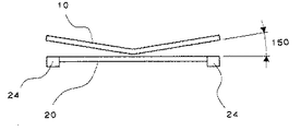
また、固定刃10は、図6のように切断幅方向であって、かつ可動刃20への圧接方向つまり図5の左方向にあらかじめ反りを形成させていることが望ましい。その理由は、切断の開始から終了までの間、可動刃20と固定刃10は常に図7に示す交差角150を持って切断するので、刃物が摩耗しても切れ味が維持されて良好な切断ができるからである。
尚、図7は図6に示す可動刃20と固定刃10を下方向から見た図であるが、交差角150の説明のためその位置関係は図6とは異なる。
Further, it is desirable that the fixed
7 is a view of the
本発明のシート材切断装置は、分離構造を採用しても、高い切断精度を維持することが出来るため、シート材の交換が頻繁に行われる商店のレジ等のプリンタ、あるいは券売機、発券機等に採用されるシート材切断装置として極めて有用である。 Since the sheet material cutting device of the present invention can maintain high cutting accuracy even if a separation structure is adopted, a printer such as a cash register of a store where the sheet material is frequently replaced, a ticket vending machine, or a ticket issuing machine It is extremely useful as a sheet material cutting device employed in the above.
10 固定刃、11 刃先、12 固定刃ベース、13 固定刃ホルダ、14 圧接バネ、15 ネジ、20 可動刃、21V字型に窪んだ刃先、22 切り込み部、23 勘合部、24 切断動作方向の両端、30 フレーム、31 可動刃の幅方向位置を規制するガイド、32 固定刃への圧接方向位置を規制するガイド、33 可動刃曲げ部、40 駆動ピン、50 ウォームホイール、60 ウォームギヤ、70 モータ、80 スイッチ、90 スライダ、100 ピン、110 ナット、120 ワッシャ、130 ホルダ
DESCRIPTION OF
Claims (5)
Priority Applications (1)
| Application Number | Priority Date | Filing Date | Title |
|---|---|---|---|
| JP2003308367A JP2005074571A (en) | 2003-09-01 | 2003-09-01 | Sheet material cutting apparatus |
Applications Claiming Priority (1)
| Application Number | Priority Date | Filing Date | Title |
|---|---|---|---|
| JP2003308367A JP2005074571A (en) | 2003-09-01 | 2003-09-01 | Sheet material cutting apparatus |
Publications (2)
| Publication Number | Publication Date |
|---|---|
| JP2005074571A true JP2005074571A (en) | 2005-03-24 |
| JP2005074571A5 JP2005074571A5 (en) | 2006-09-28 |
Family
ID=34410858
Family Applications (1)
| Application Number | Title | Priority Date | Filing Date |
|---|---|---|---|
| JP2003308367A Pending JP2005074571A (en) | 2003-09-01 | 2003-09-01 | Sheet material cutting apparatus |
Country Status (1)
| Country | Link |
|---|---|
| JP (1) | JP2005074571A (en) |
Cited By (3)
| Publication number | Priority date | Publication date | Assignee | Title |
|---|---|---|---|---|
| JP2006326788A (en) * | 2005-05-30 | 2006-12-07 | Hitachi Metal Precision:Kk | Sheet material-cutting device |
| WO2007088760A1 (en) * | 2006-01-31 | 2007-08-09 | Citizen Holdings Co., Ltd. | Sheet material cutter and printer |
| CN106272706A (en) * | 2016-08-31 | 2017-01-04 | 江苏大亚印务有限公司 | A kind of die-cutting rule and using method thereof |
-
2003
- 2003-09-01 JP JP2003308367A patent/JP2005074571A/en active Pending
Cited By (5)
| Publication number | Priority date | Publication date | Assignee | Title |
|---|---|---|---|---|
| JP2006326788A (en) * | 2005-05-30 | 2006-12-07 | Hitachi Metal Precision:Kk | Sheet material-cutting device |
| WO2007088760A1 (en) * | 2006-01-31 | 2007-08-09 | Citizen Holdings Co., Ltd. | Sheet material cutter and printer |
| JP2007203390A (en) * | 2006-01-31 | 2007-08-16 | Citizen Holdings Co Ltd | Sheet material cutting device and printer |
| US8267603B2 (en) | 2006-01-31 | 2012-09-18 | Citizen Holdings Co., Ltd. | Sheet material cutter and printer |
| CN106272706A (en) * | 2016-08-31 | 2017-01-04 | 江苏大亚印务有限公司 | A kind of die-cutting rule and using method thereof |
Similar Documents
| Publication | Publication Date | Title |
|---|---|---|
| KR100234589B1 (en) | Printer having cutting apparatus and protective device for use in a printer | |
| US20050247180A1 (en) | Lower cutter for compact printer and cutting device including the same | |
| US20080127796A1 (en) | Paper cutter | |
| JP2005074571A (en) | Sheet material cutting apparatus | |
| JP3593794B2 (en) | Cutter mechanism | |
| EP0983861A2 (en) | Printer | |
| KR101432362B1 (en) | Printer apparatus | |
| JP7108487B2 (en) | Cutter device and printer | |
| US6629788B2 (en) | Method and apparatus for clamping and adjusting an anti-rotation rail to adjust printhead to platen/media spacing in a printer | |
| EP2213461A1 (en) | Tape printer | |
| JP2016159375A (en) | Sheet material cutting device | |
| JPH11123692A (en) | Sheet cutting device and printing device equipped therewith | |
| JP2001347485A (en) | Separate type slide sheet cutter | |
| JP4840466B2 (en) | Printer | |
| JP4803158B2 (en) | Cutter device and printer using the same | |
| GB2154924A (en) | Cutting mechanism | |
| JPH09277189A (en) | Cutting device | |
| JP6596980B2 (en) | Cutting mechanism and printing apparatus | |
| JP3864659B2 (en) | Head pressing mechanism and printer having the same | |
| JP4449572B2 (en) | Printer | |
| JP4016288B2 (en) | Recording device | |
| JPH06320480A (en) | Sheet cutting device | |
| JP2004203557A (en) | Printer | |
| US958455A (en) | Paper-cutting shears. | |
| JP2006123097A (en) | Sheet material cutting apparatus |
Legal Events
| Date | Code | Title | Description |
|---|---|---|---|
| A521 | Written amendment |
Free format text: JAPANESE INTERMEDIATE CODE: A523 Effective date: 20060810 |
|
| A621 | Written request for application examination |
Free format text: JAPANESE INTERMEDIATE CODE: A621 Effective date: 20060810 |
|
| A131 | Notification of reasons for refusal |
Free format text: JAPANESE INTERMEDIATE CODE: A131 Effective date: 20090410 |
|
| A977 | Report on retrieval |
Free format text: JAPANESE INTERMEDIATE CODE: A971007 Effective date: 20090417 |
|
| A02 | Decision of refusal |
Free format text: JAPANESE INTERMEDIATE CODE: A02 Effective date: 20090731 |