JP2005073738A - Clip table and calling slave unit - Google Patents
Clip table and calling slave unit Download PDFInfo
- Publication number
- JP2005073738A JP2005073738A JP2003304503A JP2003304503A JP2005073738A JP 2005073738 A JP2005073738 A JP 2005073738A JP 2003304503 A JP2003304503 A JP 2003304503A JP 2003304503 A JP2003304503 A JP 2003304503A JP 2005073738 A JP2005073738 A JP 2005073738A
- Authority
- JP
- Japan
- Prior art keywords
- mattress
- top plate
- bottom plate
- contact
- fastening piece
- Prior art date
- Legal status (The legal status is an assumption and is not a legal conclusion. Google has not performed a legal analysis and makes no representation as to the accuracy of the status listed.)
- Pending
Links
- 230000007246 mechanism Effects 0.000 claims abstract description 40
- 238000003780 insertion Methods 0.000 claims description 22
- 230000037431 insertion Effects 0.000 claims description 22
- 238000001514 detection method Methods 0.000 claims description 20
- 229920001971 elastomer Polymers 0.000 claims description 15
- 239000000806 elastomer Substances 0.000 claims description 10
- 229920003225 polyurethane elastomer Polymers 0.000 claims description 5
- 229920005749 polyurethane resin Polymers 0.000 claims description 5
- 229920002050 silicone resin Polymers 0.000 claims description 5
- 238000002513 implantation Methods 0.000 claims description 4
- 239000000463 material Substances 0.000 claims description 3
- 238000000034 method Methods 0.000 description 3
- 239000002390 adhesive tape Substances 0.000 description 2
- QVGXLLKOCUKJST-UHFFFAOYSA-N atomic oxygen Chemical compound [O] QVGXLLKOCUKJST-UHFFFAOYSA-N 0.000 description 2
- 230000000694 effects Effects 0.000 description 2
- 238000001802 infusion Methods 0.000 description 2
- 238000005259 measurement Methods 0.000 description 2
- 229910052760 oxygen Inorganic materials 0.000 description 2
- 239000001301 oxygen Substances 0.000 description 2
- 208000019901 Anxiety disease Diseases 0.000 description 1
- 208000000260 Warts Diseases 0.000 description 1
- 239000004840 adhesive resin Substances 0.000 description 1
- 229920006223 adhesive resin Polymers 0.000 description 1
- 230000036506 anxiety Effects 0.000 description 1
- 230000008878 coupling Effects 0.000 description 1
- 238000010168 coupling process Methods 0.000 description 1
- 238000005859 coupling reaction Methods 0.000 description 1
- 239000007943 implant Substances 0.000 description 1
- 230000035945 sensitivity Effects 0.000 description 1
- 201000010153 skin papilloma Diseases 0.000 description 1
Images
Landscapes
- Invalid Beds And Related Equipment (AREA)
- Accommodation For Nursing Or Treatment Tables (AREA)
Abstract
Description
本発明は、ベッドのマットレスに装着されて臨床機器を保持するクリップテーブル、及びベッドのマットレスに固定される呼出子機に関する。 The present invention relates to a clip table that is mounted on a bed mattress and holds clinical equipment, and a caller that is fixed to the bed mattress.
被看護者が看護者を呼び出すために用いられる呼出装置のうち被看護者側に設置される呼出子機がある。呼出子機には、被看護者の様態に応じて様々な形態のものがある。ベッドの上で身動きの取れる被看護者には、呼出装置の親機に有線で接続された押しボタン式のスイッチを備える呼出子機が用いられることが多い。押しボタン指揮の呼出子機の場合、枕元に置いたりベッドの頭側のフレームに掛けておいたりするなど被看護者が容易に手の届くところに配置される。 There is a caller installed on the care receiver side among call devices that are used by the care worker to call the caregiver. There are various types of call handsets according to the condition of the patient. For a nurse who can move on a bed, a caller having a push button type switch connected to the parent machine of the caller by wire is often used. In the case of a push button commanding handset, it is placed at a place where the nurse can easily reach, such as placing it on the bedside or hanging it on the frame on the head of the bed.
一方、ベッドの上で押しボタン式の呼出子機の操作が困難な被看護者に対しては、接触検知式、吐息検知式、音声検知式などのスイッチ(センサ)を備える呼出子機が用いられる(例えば、特許文献1参照。)。この呼出子機は、枕の下に差し込まれる敷板とこの敷板にコントロールボックスを載置するための取付台とを備える。各センサの検知部は、被看護者が操作できる位置に自在アームでセットされる。 On the other hand, a caller with a switch (sensor) such as a contact detection type, an exhalation detection type, and a voice detection type is used for a patient who is difficult to operate a push button type caller on a bed. (For example, refer to Patent Document 1). This calling machine includes a floor plate inserted under the pillow and a mounting base for mounting the control box on the floor plate. The detection part of each sensor is set with a free arm at a position where the care recipient can operate.
また、睡眠中に枕が移動しないように敷布団やマットレスに枕を面ファスナ、チャックボタンとボタン孔、ホック、クリップ、紐の少なくとも1つで保持させる枕取付具がある(例えば、特許文献2参照。)。この枕取付具は、リクライニング機構を備えるベッドや椅子に適用することで、上体を起した場合でも枕がずり落ちない。また、枕保持部の脇には、ポケットが設けられ、リクライニング機構のリモコンのほか、テレビやエアコンなどのリモコンを入れておくことで、これらのリモコンを枕元に保持している。
しかしながら、枕の下に敷板を差し込んでスイッチを被看護者の操作可能範囲に設置する呼出子機の場合、敷板は、枕及び被看護者の頭の重みで押えられているだけである。したがって、何かの拍子に枕が動いたり、頭を動かしたりすると、被看護者が利用しやすい位置から呼出子機のスイッチがずれてしまう。また、呼出子機の重さで敷板が枕とマットレスとの間から滑ってずり落ちてしまうので、リクライニング機構を有したベッドに適用することができない。 However, in the case of a handset that inserts a floorboard under the pillow and installs the switch within the range where the caregiver can operate, the floorboard is only pressed by the weight of the pillow and the head of the nurse. Therefore, if the pillow moves or the head is moved at any time, the switch of the caller is displaced from a position that is easy for the nurse to use. In addition, since the floorboard slides from the pillow and the mattress due to the weight of the handset, it cannot be applied to a bed having a reclining mechanism.
一方、敷布団やマットレスの表地、あるいはこれらのカバーに枕を保持するように呼出子機を枕元に取り付ける場合、リクライニング機構を有したベッドに適用しても呼出子機がずり落ちることはないが、呼出子機の重みで敷布団やマットレスの表地、或いはこれらのカバーが撚れてしまい、被看護者が利用しやすい位置からスイッチがずれてしまう。また、枕元にあると分かっていても、緊急時には視認できる範囲にないと、被看護者にとって不安感が募る。 On the other hand, when the caller is attached to the bedside to hold a pillow on the mattress or mattress, or on these covers, the caller will not slide down even when applied to a bed with a reclining mechanism. The weight of the child machine causes the mattress or mattress outer material or the cover to be twisted, and the switch is displaced from a position that is easy for the care recipient to use. Moreover, even if it is known that it is at the bedside, if it is not in a range that can be seen in an emergency, anxiety is raised for the nurse.
呼出子機をベッドサイドに置かれたスタンドに固定する場合もあるが、スタンドは、容易に移動させることができるため、見舞い客が不用意に触れて移動させてしまう場合がある。そして、リクライニング機構を備えるベッドを利用している場合、上体の角度を変える毎に呼出子機の位置を調整しなければならない。また、リクライニング機構を備えるベッドの頭側のフレームに呼出子機を固定する場合、同様に状態の位置を変える毎に呼出子機の位置を調整しなければならない。 In some cases, the caller is fixed to a stand placed on the bedside. However, since the stand can be easily moved, a visitor may inadvertently touch and move the stand. And when using the bed provided with a reclining mechanism, the position of the handset must be adjusted each time the upper body angle is changed. Further, when the caller is fixed to the frame on the head side of the bed provided with the reclining mechanism, the position of the caller must be adjusted each time the state is changed.
そこで、本発明は、リクライニング機構を備えるベッドにも適用する場合にも被看護者が利用しやすい位置に臨床機器を保持することのできるクリップテーブル、及びスイッチを被看護者が利用しやすい位置に設置できる呼出子機を提供することを目的とする。 Therefore, the present invention provides a clip table and a switch that can hold a clinical device at a position that can be easily used by a patient even when applied to a bed having a reclining mechanism, and a switch that can be used by a patient. An object is to provide a handset that can be installed.
本発明に係るクリップテーブルは、マットレスの表側に少なくとも一部を接して配置される天板と、マットレスの裏側に少なくとも一部を接して配置される底板と、天板と底板とを連結する側板と、天板から前記側板までの範囲の外面の一部に設けられて臨床機器が固定される機器装着部とを有する。 The clip table according to the present invention includes a top plate disposed at least partially in contact with the front side of the mattress, a bottom plate disposed at least partially in contact with the back side of the mattress, and a side plate connecting the top plate and the bottom plate. And a device mounting portion provided on a part of the outer surface in the range from the top plate to the side plate and to which the clinical device is fixed.
または、マットレスの表側に少なくとも一部を接して配置される天板と、マットレスの裏側に少なくとも一部を接して配置される底板と、天板と底板との間の距離を変化させる調整機構と、天板から調整機構までの範囲の外面の一部に設けられて臨床機器が固定される機器装着部とを備えるクリップテーブルとする。 Alternatively, a top plate disposed at least partially in contact with the front side of the mattress, a bottom plate disposed at least partially in contact with the back side of the mattress, and an adjustment mechanism that changes the distance between the top plate and the bottom plate. The clip table includes a device mounting portion that is provided on a part of the outer surface in the range from the top plate to the adjustment mechanism and to which the clinical device is fixed.
ここでいう臨床機器とは、呼出装置の呼出子機、呼出装置の親機に通じるインターホン、リクライニング機構などを備える多機能ベッドのリモコンのほか、点滴中のチューブ、酸素供給用のチューブ、心電計測用のコード、ペースメーカ用のコードを含めたものを指す。また、室内及び枕元の照明用のリモコン、テレビ用またはオーディオ用のリモコンであってもよい。 The clinical equipment here refers to the calling device of the calling device, the intercom leading to the calling device's parent device, a multi-function bed remote control equipped with a reclining mechanism, etc., as well as a tube during infusion, a tube for supplying oxygen, an electrocardiogram This includes cords for measurement and cords for pacemakers. Further, it may be a remote controller for lighting in the room and bedside, a remote controller for television or audio.
この場合、調整機構は、天板から底板に向かって延びて断面が鋸波形の係合部をマットレスに面した側に有する係合片と、底板から天板に向かって延びて断面が鋸波形の受部を係合部に面する内側面に有する差込部と、係合片を差込部に差し込んだ状態で係合片と差込部との間に生じる隙間に挿入される楔片とを備える。または、調整機構は、天板から底板に向かって延びる第1締結片と、底板から天板に向かって延びる第2締結片と、第1締結片と第2締結片とを重ね合わせた状態でマットレスに近い方に設けられる植込みボルトと、第1締結片と第2締結片とを重ね合わせた状態でマットレスに遠い方に設けられて植込みボルトが挿通される長孔と、植込みボルトの先端に螺合されて第1締結片と第2締結片とを固定する締付部材とを備える。 In this case, the adjusting mechanism includes an engagement piece extending from the top plate toward the bottom plate and having an engagement portion having a saw-tooth cross section on the side facing the mattress, and a cross-section having a saw-tooth cross section extending from the bottom plate toward the top plate. And a wedge piece inserted into a gap formed between the engagement piece and the insertion portion in a state in which the engagement piece is inserted into the insertion portion. With. Alternatively, the adjustment mechanism is in a state where the first fastening piece extending from the top plate toward the bottom plate, the second fastening piece extending from the bottom plate toward the top plate, and the first fastening piece and the second fastening piece are overlapped. Implant bolts that are provided closer to the mattress, long holes that are provided farther from the mattress in a state where the first fastening piece and the second fastening piece are overlapped, and a tip of the implantation bolt. A fastening member that is screwed to fix the first fastening piece and the second fastening piece is provided.
また、ずり落ちることを防止するために、天板と底板と側板との少なくともマットレスに接する一部に摩擦係数の高い滑止部材を設ける。滑止部材は、ゴム、ポリウレタン樹脂エラストマ、発砲ポリウレタンエラストマ、シリコーン樹脂エラストマの中から選択されるいずれか1つの材質である。 In order to prevent sliding, a non-slip member having a high friction coefficient is provided on at least a part of the top plate, the bottom plate, and the side plate that are in contact with the mattress. The non-slip member is made of any one material selected from rubber, polyurethane resin elastomer, foamed polyurethane elastomer, and silicone resin elastomer.
本発明に係る呼出子機は、被看護者が看護者を呼び出すために用いられる呼出装置のうち被看護者側に設置される呼出子機を前提とする。そして、マットレスの表側に少なくとも一部を接して配置される天板と、マットレスの裏側に少なくとも一部を接して配置される底板と、天板と底板とを連結する側板と、天板から側板までの外面の一部に基部が固定されるとともに操作部を有する先端部が被看護者の周辺に位置決めされるスイッチとを備える。 The calling device according to the present invention is premised on a calling device installed on the care recipient side among calling devices used by the care recipient to call the nurse. And a top plate disposed at least partially in contact with the front side of the mattress, a bottom plate disposed at least partially in contact with the back side of the mattress, a side plate connecting the top plate and the bottom plate, and the top plate to the side plate. The base is fixed to a part of the outer surface up to this point, and the tip having the operation part is provided with a switch positioned around the care receiver.
または、マットレスの表側に少なくとも一部を接して配置される天板と、マットレスの裏側に少なくとも一部を接して配置される底板と、天板と底板との間の距離を変化させる調整機構と、天板から調整機構までの範囲の外面の一部に基部が固定されるとともに操作部を有する先端部が被看護者の周辺に位置決めされるスイッチとを備える。 Alternatively, a top plate disposed at least partially in contact with the front side of the mattress, a bottom plate disposed at least partially in contact with the back side of the mattress, and an adjustment mechanism that changes the distance between the top plate and the bottom plate. The base is fixed to a part of the outer surface in the range from the top plate to the adjustment mechanism, and the tip having the operation portion is provided with a switch positioned around the care recipient.
この場合、調整機構は、天板から底板に向かって延びて前記マットレスに面した側に断面が鋸波形の係合部を有する係合片と、底板から天板に向かって延びて係合部と嵌合する断面が鋸波型の受部を内面に有する差込部と、係合片を差込部に差し込んだ状態で係合片と差込部との間に生じる隙間に挿入される楔片とを備える。 In this case, the adjustment mechanism includes an engagement piece having an engagement portion having a sawtooth cross section on the side facing the mattress extending from the top plate toward the bottom plate, and an engagement portion extending from the bottom plate toward the top plate. The insertion section having a saw-tooth shaped receiving part on the inner surface and a gap formed between the engagement piece and the insertion part in a state where the engagement piece is inserted into the insertion part A wedge piece.
また、スイッチは、押しボタン式、接触検知式、吐息圧力検知式、音声検知式のいずれか1つとする。 The switch is one of a push button type, a contact detection type, an exhalation pressure detection type, and a voice detection type.
本発明に係るクリップテーブルによれば、マットレスに対してしっかりと固定される。その結果、リクライニング機構を備えたベッドに適用し、上体を起したり寝せたりした場合でも、ベッドに横たわる被看護者に対して同じ位置に臨床機器を保持することができる。したがって、臨床機器のケーブルやチューブが煩雑にならないので、特に、呼出子機をクリップテーブルに取付けておく場合、被看護者は、呼出子機の在り処が分かっているので安心感が得られ、緊急時にもパニックに陥ることがない。 The clip table according to the present invention is firmly fixed to the mattress. As a result, even when applied to a bed equipped with a reclining mechanism and the upper body is raised or laid down, the clinical device can be held at the same position with respect to the patient lying on the bed. Therefore, since the cables and tubes of clinical equipment do not become complicated, especially when the caller is attached to the clip table, the nurse can feel secure because the location of the caller is known. No panic during an emergency.
調整機構を備える本発明のクリップテーブルによれば、天板と底板の距離を変化させることができる。したがって、厚さの異なるマットレスにも固定することができ、汎用性に優れている。また、滑止部材を少なくともマットレスに接する一部に設けた本発明のクリップテーブルによれば、マットレスに対してずれ難くなり、より確かに固定することができる。 According to the clip table of the present invention including the adjustment mechanism, the distance between the top plate and the bottom plate can be changed. Therefore, it can be fixed to mattresses having different thicknesses and is excellent in versatility. Further, according to the clip table of the present invention in which the non-slip member is provided at least at a part in contact with the mattress, it is difficult to be displaced with respect to the mattress and can be more reliably fixed.
本発明に係る呼出子機によれば、マットレスに対してしっかりと固定されるので、ベッドに横たわる被看護者に対して、操作部が先端部に設けられたスイッチを被看護者の周辺に位置決めすることができる。特に、重度の被看護者にとって、より操作しやすい位置に呼出子機のスイッチがあることがより高い安心感に繋がる。したがって、被看護者は、呼出子機の在り処が分かっているので安心感が得られ、緊急時にもパニックに陥ることがない。 According to the caller according to the present invention, the switch is firmly fixed to the mattress, so that the switch provided on the distal end portion of the operation unit is positioned around the patient who is lying on the bed. can do. In particular, the presence of a caller switch at a position that is easier to operate for a severely cared person leads to a higher level of security. Therefore, the nurse can feel safe because he / she knows where the handset is located, and does not panic during an emergency.
また、調整機構を備える本発明の呼出子機によれば、厚さの異なるマットレスにも固定することができ、汎用性に優れている。 Further, according to the calling device of the present invention including the adjusting mechanism, it can be fixed to mattresses having different thicknesses, and is excellent in versatility.
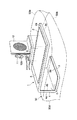
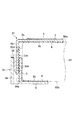
本発明に係る第1の実施形態のクリップテーブル1について、図1及び図3を参照して説明する。図1に示すクリップテーブル1は、天板2と底板3と側板4とを備える。天板2は、マットレス50の表側(上側)50aに密着するように配置される。底板3は、マットレス50の裏側(下側)50bに密着するように配置される。側板4は、マットレス50の厚さよりもやや狭い距離に天板2と底板3とを一体に連結している。
A clip table 1 according to a first embodiment of the present invention will be described with reference to FIGS. 1 and 3. A clip table 1 shown in FIG. 1 includes a
マットレス50と接していない天板2の外面2aには、臨床機器を固定する機器装着部5が設けられている。ここでいう臨床機器とは、呼出装置の呼出子機11、呼出装置の親機に通じるインターホン12、リクライニング機構などを備える多機能ベッドのリモコンのほか、点滴中のチューブ、酸素供給用のチューブ、心電計測用のコード、ペースメーカ及びそのコードを含めたものを指す。また、室内及び枕元の照明用のリモコン、テレビ・ビデオ用またはオーディオ用のリモコンであってもよい。
On the
図1では、臨床機器の代表として、呼出装置の呼出子機11及び親機に通じるインターホン12を取り付ける状態を例示している。呼出子機11は、押しボタン式であって、インターホン12の脇に設けられたホルダ12aに保持されている。呼出子機11は、押しボタン式のほか、四肢の自由度の少ない重度の被看護者Pに対して用いられる接触検知式、吐息圧力検知式、音声検知式であっても良い。
In FIG. 1, as a representative of clinical equipment, a state in which a
機器装着部5は、マットレス50に横たわる被看護者Pが容易に届く位置であれば良いので、天板2から側板4までの範囲の外面2a,4aの一部に設けられていても良いし、複数箇所に設けられていても良い。図1では、機器装着部5に面状ファスナを用いた例を示す。面状ファスナは、側板4から離れる方向に複数列設けても良いし、或いは、側板4に沿う方向に複数列設けても良い。機器装着部5は、用途に応じて載置する機器を容易に変更できるように、面状ファスナのほか、スナップ、ホック、クリップ、ねじ、粘着テープ、粘着性樹脂部材など、着脱可能でかつ安定性に優れた固定手段によって臨床機器を固定できるように設けられていても良い。
The
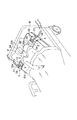
マットレス50と接する天板2、側板4、及び底板3の内側2b,4b,3bには、滑止部材6が設けられている。滑止部材6は、マットレス50に対して摩擦係数の高い部材でできており、機器装着部5に取り付けた臨床機器の位置がずれることを防止する。特に、図3に示すようにリクライニング機構を備えたベッドBにクリップテーブル1を装着した場合、マットレス50の上体部分50cを起してもクリップテーブル1がずり落ちることを防止することができる。滑止部材6は、ゴム、ポリウレタン樹脂エラストマ、発砲ポリウレタンエラストマ、シリコーン樹脂エラストマのいずれでも良い。なお、滑止部材6は、クリップテーブル1がずれることを防止できれば良いので、マットレス50に接する範囲の一部もしくは複数箇所に分けて設けられていても良い。また、接触面は、平坦な状態に限らず、いぼ状の突起を多数設けたり、波形の凹凸を設けたり、格子状の凸部を設けたりしても良い。
リクライニング機構付のベッドBに横たわる被看護者Pの右手側に図1のクリップテーブル1を装着した状態を図3に示す。呼出装置のインターホン12が機器装着部5に固定されており、ボタン式の呼出子機11がこのインターホン12上端に設けられたホルダ12aに装着されている。図3に示すように、リクライニング機構によってマットレス50の上体部分50cを起しても、インターホン12や呼出子機11が被看護者Pに対してずれることがない。したがって、被看護者Pは、呼出子機11やインターホン12の在り処がわかっているので、緊急時にパニックに陥ることなく落ち着いて操作することができる。
FIG. 3 shows a state in which the clip table 1 of FIG. 1 is mounted on the right hand side of the patient P lying on the bed B with the reclining mechanism. An
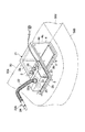
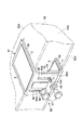
本発明に係る第2の実施形態の呼出子機21について、図2及び図3を参照して説明する。図2に示す呼出子機21は、被看護者Pが看護者を呼び出すために用いられる呼出装置の子機であって、天板2と底板3と側板4とスイッチ22とを備える。天板2は、マットレス50の表側50aに密着するように配置される。底板3は、マットレス50の裏側50bに密着するように配置される。側板4は、マットレス50の厚さよりもやや狭い距離に天板2と底板3とを一体に連結している。
A
天板2及び底板3のマットレス50に接する側となる内面2b,3bには、滑止部材6が設けられている。滑止部材6は、マットレス50に対して摩擦係数の高い部材であれば良いので、第1の実施形態で例示した、ゴム、ポリウレタン樹脂エラストマ、発砲ポリウレタンエラストマ、シリコーン樹脂エラストマのいずれでも良い。また、滑止部材6は、マットレス50に接する側板4部分も含めた全面に設けても良いし、一部または複数箇所に分けて設けても良い。
Antiskid
スイッチ22は、天板2の上面(外面)2aに基部22aが粘着テープ23で固定されており、操作部24を有する先端部22bが図3に示すように被看護者Pの口元に位置決めされている。スイッチ22は、接触検知式であって、被看護者Pが操作部24に触れることによって変化する静電容量を読取ることで作動する。スイッチ22の基部22aに設けられた制御ボックス25には、操作部24の感度及び触れる間隔を調整するための制御回路が内蔵されており、摘み26でそれぞれ調整できるようになっている。
The
スイッチ22は、接触検知式の他、吐息圧力検知式、音声検知式、押しボタン式などでも良い。いずれの場合も、四肢の自由度が少ない重度の被看護者Pに適用できる。吐息圧力検知式のスイッチおよび音声検知式のスイッチの場合、口元にスイッチの先端部が配置される。また、接触検知式のスイッチ22や押しボタン式のスイッチの場合、口元以外に被看護者Pが容易に動かすことのできる身体の一部に近い位置に配置することができる。
In addition to the contact detection type, the
以上のように設けられた呼出子機21は、マットレス50を挟み込むことによってマットレス50に固定されているので、図3に示すようにリクライニング機構を備えるベッドBに適用して上体部分50cを起したり寝かせたりした場合にも、被看護者Pの利用しやすい位置にスイッチ22の操作部24を保持することができる。したがって、四肢の自由度が少ない重度の被看護者Pであっても、常に利用しやすい位置に呼出子機21のスイッチ22の操作部24があることで安心感が得られ、緊急時にもパニックに陥らずに操作することができる。
Since the
本発明に係る第3の実施形態のクリップテーブル31について図4及び図5を参照して説明する。なお、図1に示す第1の実施形態のクリップテーブル1と同じ機能を有する構成要素については、同一の符号を付してその説明を省略する。 A clip table 31 according to a third embodiment of the present invention will be described with reference to FIGS. In addition, about the component which has the same function as the clip table 1 of 1st Embodiment shown in FIG. 1, the same code | symbol is attached | subjected and the description is abbreviate | omitted.
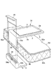
図4に示すクリップテーブル31は、天板2と底板3とが調整機構32によって連結されている。調整機構32は、天板2と底板3との間の距離を変化させる。調整機構32は、係合片33と差込部34と楔片35とを備える。係合片33は、天板2から底板3に向かって延びており、断面が鋸波形の係合部33aをマットレス50に面した側に有している。差込部34は、底板3から天板2に向かって係合片33を囲う箱形筒状に延びており、断面が鋸波形の受部34aを係合部33aに面した内面に有している。
In the clip table 31 shown in FIG. 4, the
楔片35は、図5に示すように、係合片33が差込部34に差し込まれて係合部33aと受部34aとが噛み合わさった状態で、係合片33と差込部34との間に生じる隙間に挿入される。楔片35を差し込むことによって、係合部33aと受部34aとの嵌合が外れなくなるとともに、楔片35を抜くことによって、係合片33の差込部34に対する差込量を鋸波形のピッチに応じて容易に調節することができる。
As shown in FIG. 5, the
マットレス50と接する天板2の下面(内面)2b、底板の上面(内面)3b、及び差込部34の内側面34bには、図5に示すように滑止部材6が設けられている。滑止部材6は、他の実施形態と同様にゴム、ポリウレタン樹脂エラストマ、発砲ポリウレタンエラストマ、シリコーン樹脂エラストマのいずれでも良い。
As shown in FIG. 5, a
以上のように構成されたクリップテーブル31は、次のようにしてマットレス50に取り付けられる。まず、マットレス50の側部50dと差込部34の内側面34bとが接する状態で、マットレス50の下に底板3を敷く。次に、差込部34に係合片33が挿入されるようにマットレス50の上から天板2を押し当てる。マットレス50の厚さよりも天板2と底板3の距離が近くなるように天板2を押さえ込んだ状態で、最後に楔片35を差込部34と係合片33との隙間に挿入する。また、取外す場合は、楔片35を抜き取り、天板2を動かすことで係合片33の係合部33aが差込部34の受部34aから容易に外れる。
The clip table 31 configured as described above is attached to the
このように、クリップテーブル31は、係合部33aと受部34aとの噛合い量、すなわち天板2と底板3との距離を調整することができるので、厚さの異なるマットレス50にも対応することができるとともに、天板2と底板3とがマットレス50を挟み込む力を調節することができる。したがって、天板2に設けられた機器装着部5に固定された臨床機器を被看護者Pが利用しやすい位置に保持することができる。また、滑止部材6に逆らってマットレス50を天板2と底板3との間に差し込む必要がないので、容易に装着することができる。
As described above, the clip table 31 can adjust the amount of engagement between the engaging
本発明に係る第4の実施形態のクリップテーブル41について、図6を参照して説明する。なお、図1に示す第1の実施形態のクリップテーブル1または図4に示す第3の実施形態のクリップテーブル31と同じ機能を有する構成要素については、同一の符号を付してその説明を省略する。 A clip table 41 according to a fourth embodiment of the present invention will be described with reference to FIG. In addition, about the component which has the same function as the clip table 1 of 1st Embodiment shown in FIG. 1, or the clip table 31 of 3rd Embodiment shown in FIG. 4, the same code | symbol is attached | subjected and the description is abbreviate | omitted. To do.
図6に示すクリップテーブル41は、天板2と底板3との間の距離を変化させる調整機構42が図4に示した第3の実施形態におけるクリップテーブル41の調整機構42と異なる。図6に示すクリップテーブル41の調整機構42は、第1締結片43と第2締結片44と植込みボルト45と長孔46と締付部材とを有する。
The clip table 41 shown in FIG. 6 is different from the
第1締結片43は、天板2から底板3に向かって延びており、第2締結片44は、底板3から天板2に向かって延びている。植込みボルト45は、第1締結片43と第2締結片44とを重ね合わせた状態でマットレス50に近い方、本実施形態では、底板3に設けられている。長孔46は、第1締結片43と第2締結片44とを重ね合わせた状態でマットレス50から遠い方、本実施形態では、第1締結片43に設けられている。締結部材47は、長孔46に通された植込みボルト45の先端45a側から螺合され、第1締結片43と第2締結片44とを互いに固定する。
The
なお、締結部材47を植込みボルト45に締めこむ際に長孔46の縁46aと局部的に接触しないように、第1締結片43と締結部材47との間にワッシャ48を入れている。また、第1締結片43の外側43aには、天板2の上面(外面)2aと同様に機器装着部5が設けられている。本実施形態では、第2締結片44がマットレス50側になるように第1締結片43と第2締結片44とを重ね合わせたため、第1締結片43に長孔46を形成し、第2締結片44に植込みボルト45を設けたが、第1締結片43がマットレス50側になるように第1締結片43と第2締結片44を重ね合わせた場合は、長孔46を第2締結片44に設け、植込みボルト45を第1締結片43に設ける。
A
以上のように構成されたクリップテーブル41は、次の手順でマットレス50に装着される。まず、第2締結片とマットレス50の側部50dとが接する状態で底板3がマットレス50の下に敷かれる。次に、長孔46に植込みボルト45を通して第1締結片43と第2締結片44を重ね合わせる。そして、マットレス50の厚さよりも天板2と底板3との間の距離が近くなるように天板2をマットレス50に押し付けた状態で、締結部材47を植込みボルト45に螺合して第1締結片43と第2締結片44とを固定する。
The clip table 41 configured as described above is attached to the
上述の手順以外に次の手順でも良い。予め第1締結片43と第2締結片44とを重ね合わせて天板2と底板3との距離が自由に変化する程度に締結部材47を植込みボルト45に螺合しておく。マットレス50の厚さよりも天板2と底板3との間の距離が離れた状態でマットレス50の縁にクリップテーブル41を嵌める。そして、天板2と底板3との間の距離が近くなるように天板2及び底板3をマットレス50に押し付けた状態で締結部材47を締め込み、第1締結片43と第2締結片44とを固定する。
In addition to the above procedure, the following procedure may be used. The
このように、図6に示すクリップテーブル41は、調整機構42によって天板2と底板3との間の距離を変化させることができるので、図1に示した第1の実施形態のクリップテーブル1が有する効果に加えて、図4に示した第3の実施形態のクリップテーブル31が有する効果を得ることができる。
As described above, the clip table 41 shown in FIG. 6 can change the distance between the
なお、第3及び第4の実施形態におけるクリップテーブル31,41の機器装着部5には、第1の実施形態におけるクリップテーブル1の機器装着部5に固定される臨床機器として例示したものを取り付けることができる。また、第3及び第4の実施形態におけるクリップテーブル31,41に設けた調整機構32,42を第2の実施形態における呼出子機21の天板2と底板3との結合構造に適用しても良い。
In addition, what was illustrated as a clinical apparatus fixed to the
1,31,41…クリップテーブル、2…天板、2a…外面(上面)、2a…内面(下面)、3…底板、3b…上面(内面)、4…側板、4a…外面、4b…内側、5…機器装着部、6…滑止部材、11…呼出子機(臨床機器)、12…インターホン(臨床機器)、21…呼出子機、22…スイッチ、22a…基部、22b…先端部、24…操作部、32調整機構、33…係合片、33a…係合部、34…差込部、34a…受部、35…楔片、42…調整機構、43…第1締結片、43a…外側、44…第2締結片、45…植込みボルト、45a…先端、46…長孔、47…締結部材、50…マットレス、50a…表側、50b…裏側
DESCRIPTION OF
Claims (10)
前記マットレスの裏側に少なくとも一部を接して配置される底板と、
前記天板と前記底板とを連結する側板と、
前記天板から前記側板までの範囲の外面の一部に設けられて臨床機器が固定される機器装着部とを有することを特徴とするクリップテーブル。 A top plate disposed at least partially in contact with the front side of the mattress;
A bottom plate disposed at least partially in contact with the back side of the mattress;
A side plate connecting the top plate and the bottom plate;
A clip table comprising a device mounting portion provided on a part of an outer surface in a range from the top plate to the side plate to which a clinical device is fixed.
前記マットレスの裏側に少なくとも一部を接して配置される底板と、
前記天板と前記底板との間の距離を変化させる調整機構と、
前記天板から前記調整機構までの範囲の外面の一部に設けられて臨床機器が固定される機器装着部とを備えることを特徴とするクリップテーブル。 A top plate disposed at least partially in contact with the front side of the mattress;
A bottom plate disposed at least partially in contact with the back side of the mattress;
An adjustment mechanism for changing the distance between the top plate and the bottom plate;
A clip table, comprising: a device mounting portion provided on a part of an outer surface in a range from the top plate to the adjustment mechanism to which a clinical device is fixed.
マットレスの表側に少なくとも一部を接して配置される天板と、
前記マットレスの裏側に少なくとも一部を接して配置される底板と、
前記天板と前記底板とを連結する側板と、
前記天板から前記側板までの範囲の外面の一部に基部が固定されるとともに操作部を有する先端部が前記被看護者の周辺に位置決めされるスイッチとを備えることを特徴とする呼出子機。 Among the calling devices used by the caregiver to call the nurse,
A top plate disposed at least partially in contact with the front side of the mattress;
A bottom plate disposed at least partially in contact with the back side of the mattress;
A side plate connecting the top plate and the bottom plate;
A caller having a base fixed to a part of an outer surface in a range from the top plate to the side plate, and a switch having a distal end portion having an operation portion positioned around the care recipient. .
マットレスの表側に少なくとも一部を接して配置される天板と、
前記マットレスの裏側に少なくとも一部を接して配置される底板と、
前記天板と前記底板との間の距離を変化させる調整機構と、
前記天板から前記調整機構までの範囲の外面の一部に基部が固定されるとともに操作部を有する先端部が前記被看護者の周辺に位置決めされるスイッチとを備えることを特徴とする呼出子機。 Among the calling devices used by the caregiver to call the nurse,
A top plate disposed at least partially in contact with the front side of the mattress;
A bottom plate disposed at least partially in contact with the back side of the mattress;
An adjustment mechanism for changing the distance between the top plate and the bottom plate;
A caller comprising: a switch having a base portion fixed to a part of an outer surface in a range from the top plate to the adjustment mechanism, and a distal end portion having an operation portion positioned around the care recipient. Machine.
Priority Applications (1)
| Application Number | Priority Date | Filing Date | Title |
|---|---|---|---|
| JP2003304503A JP2005073738A (en) | 2003-08-28 | 2003-08-28 | Clip table and calling slave unit |
Applications Claiming Priority (1)
| Application Number | Priority Date | Filing Date | Title |
|---|---|---|---|
| JP2003304503A JP2005073738A (en) | 2003-08-28 | 2003-08-28 | Clip table and calling slave unit |
Publications (1)
| Publication Number | Publication Date |
|---|---|
| JP2005073738A true JP2005073738A (en) | 2005-03-24 |
Family
ID=34408173
Family Applications (1)
| Application Number | Title | Priority Date | Filing Date |
|---|---|---|---|
| JP2003304503A Pending JP2005073738A (en) | 2003-08-28 | 2003-08-28 | Clip table and calling slave unit |
Country Status (1)
| Country | Link |
|---|---|
| JP (1) | JP2005073738A (en) |
-
2003
- 2003-08-28 JP JP2003304503A patent/JP2005073738A/en active Pending
Similar Documents
| Publication | Publication Date | Title |
|---|---|---|
| US4431154A (en) | Holder for mounting on a rail and the like | |
| US10987263B2 (en) | Siderail power communication interface | |
| US20230201063A1 (en) | Method and Apparatus for Securing a Patient's Limb | |
| SG66430A1 (en) | Medical treatment device with a user interface adapted for home or limited care environment | |
| CA2517937A1 (en) | Hospital telephone and device controller | |
| US20060038097A1 (en) | Siderail mounting assembly | |
| JP3142079U (en) | Examination arm stand | |
| US20100243834A1 (en) | Decorative apparatus for an iv pole and method for use of same | |
| SG150526A1 (en) | Wrap device for a bed ensemble | |
| JP2005073738A (en) | Clip table and calling slave unit | |
| US20060031988A1 (en) | Tube and wire clip for hospital bed | |
| EP3701924B1 (en) | Medical equipment status indicator | |
| JP3697387B2 (en) | Body motion detection device | |
| US6050046A (en) | Bedside wall insulator | |
| JPH08243127A (en) | Bed with full side fence | |
| JP2017086150A (en) | Mattress equipment | |
| JP3867120B2 (en) | Side guard device for bed | |
| JP6945686B2 (en) | Mattress device | |
| KR102258305B1 (en) | Patient position fixing apparatus | |
| CN215688906U (en) | A kind of mental patient nursing restraint device | |
| JP2010068906A (en) | Bedside small article container | |
| EP4603013A1 (en) | Sensor sheet and cushion | |
| JP5838146B2 (en) | Bed equipment | |
| JP2024126753A (en) | Sensor systems and sensor structures | |
| JP2996342B1 (en) | Operation switch in electric bed |