JP2005073721A - Electronic endoscope device with integrated display - Google Patents
Electronic endoscope device with integrated display Download PDFInfo
- Publication number
- JP2005073721A JP2005073721A JP2003209726A JP2003209726A JP2005073721A JP 2005073721 A JP2005073721 A JP 2005073721A JP 2003209726 A JP2003209726 A JP 2003209726A JP 2003209726 A JP2003209726 A JP 2003209726A JP 2005073721 A JP2005073721 A JP 2005073721A
- Authority
- JP
- Japan
- Prior art keywords
- subject image
- processor
- image display
- display
- character information
- Prior art date
- Legal status (The legal status is an assumption and is not a legal conclusion. Google has not performed a legal analysis and makes no representation as to the accuracy of the status listed.)
- Withdrawn
Links
Images

Landscapes
- Instruments For Viewing The Inside Of Hollow Bodies (AREA)
- Endoscopes (AREA)
- Closed-Circuit Television Systems (AREA)
Abstract
【課題】必要なスペースを縮小して利便性を向上させた電子内視鏡装置や、その他の撮像機器、表示装置を備える電子機器における画面表示の制御方法を提供する。
【解決手段】モニタ画面34を含むモニタ32をプロセッサ30に一体化させ、さらにプロセッサ30設置時の支持面として、プロセッサ底面30Bと側面30Sとを選択可能とする。そして、プロセッサ30に対する被写体像やキャラクタ情報の表示の方向を、底面設置時と側面設置時とで自動的に切替える。さらに、キャラクタ情報については、表示方向のみならず、モニタ画面34上の表示位置を制御することにより、キャラクタ情報と被写体像との位置関係や、キャラクタ情報同士の位置関係を、底面設置時と側面設置時とで維持する。こうして、オペレータにとって、底面設置時と側面設置時とで実質上同一の被写体像、キャラクタ情報が表示される。
【選択図】 図5The present invention provides a method for controlling screen display in an electronic endoscope device that reduces the required space and improves convenience, and other electronic devices including an imaging device and a display device.
A monitor including a monitor screen is integrated with a processor, and a processor bottom surface and a side surface can be selected as a support surface when the processor is installed. Then, the display direction of the subject image and character information for the processor 30 is automatically switched between the bottom surface installation and the side surface installation. Further, regarding the character information, by controlling not only the display direction but also the display position on the monitor screen 34, the positional relationship between the character information and the subject image, and the positional relationship between the character information can be changed to the side information when the bottom surface is installed. Maintain at the time of installation. Thus, for the operator, substantially the same subject image and character information are displayed when the bottom surface is installed and when the side surface is installed.
[Selection] Figure 5
Description
【0001】
【発明の属する技術分野】
本発明は、電子内視鏡装置やビデオカメラ等の撮像機器や、携帯電話等の表示装置付き機器における、被写体像やキャラクタ情報の画面表示制御に関する。
【0002】
【従来の技術】
従来の電子内視鏡装置は、体内に挿入されるビデオスコープと、信号処理が施されるプロセッサと、観察部位を表示するモニタとから構成されている。そして、ケーブルを介してプロセッサから送信される信号に基いて、モニタ画面に観察部位の像が映し出される。この時、画面表示に関しては、被写体像を所定のエリアに表示させたり、観察されている患者名等のキャラクタ情報を表示させるために、プロセッサにおいて表示制御が施されている。
【0003】
【発明が解決しようとする課題】
モニタとプロセッサとがそれぞれ独立して設置されているため、電子内視鏡装置の設置、使用に必要なスペースが大きくなり、設置のための時間もかかり、内視鏡操作全体の効率を低下させていた。また、その他の表示機能付き電子機器についても、必ずしも使用状況に応じた画面表示が可能ではない。
【0004】
そこで本発明では、必要なスペースを縮小して電子内視鏡装置の利便性を向上させるとともに、電子内視鏡装置やその他の表示装置において、使用状況に応じた表示を可能にする画面表示の制御方法を提供することを目的とする。
【0005】
【課題を解決するための手段】
本発明における電子内視鏡装置のプロセッサは、プロセッサの表面であり、略水平方向に沿った設置面に必要に応じて支持される第1の面と、第1の面に略垂直であって必要に応じて設置面に支持される第2の面とを備えている。そして、第1の面および第2の面のうち、支持されている面がいずれであるかを検出する支持面検出手段を備え、第1の面に略平行な第1の方向および第2の面に略平行な第2の方向に沿って画像形成フレームを規定する画像形成部を備える。
【0006】
そして、第1の面が支持されている場合には、第1被写体像表示手段により、第1の方向が被写体像の左右方向、第2の方向が被写体像の上下方向として規定され、ビデオスコープの撮像素子により読み出される画像信号による、視覚される像に応じて正立している第1の被写体像が、画像形成部に表示される。ここで、正立している被写体像とは、視覚される像に応じた左右上下反転のない被写体像を意味する。また、第2の面が支持されている場合には、第2被写体像表示手段により、第2の方向が被写体像の左右方向、第1の方向が被写体像の上下方向として規定され、撮像素子により読み出される画像信号による、視覚される像に応じて正立している第2の被写体像が、画像形成部に表示される。
【0007】
同一の被写体を、第1被写体像表示手段と第2被写体像表示手段とが画像形成部に第1の被写体像と第2の被写体像としてそれぞれ表示する場合、いずれの場合においても同じ姿勢で画像形成部に対向するオペレータにとっては、第1の被写体像と第2の被写体像とは、略同一のものとして観察される。
【0008】
例えば、第1被写体像表示手段は、撮像素子から読み出される画素信号に基いた映像信号に応じて第1の被写体像を表示し、第2被写体像表示手段は、映像信号に対する間引き処理により、第1の被写体像よりもサイズの小さい第2の被写体像を表示する。
【0009】
第1被写体像表示手段と第2被写体像表示手段とは、文字や数字を含むキャラクタ情報をさらに表示可能であることが好ましい。キャラクタ信号に基いて、第1被写体像表示手段により、画像形成部の所定の位置に第1キャラクタ情報が表示され、一方、第2被写体像表示手段により、第1キャラクタ情報の画像形成部の中心に対する位置関係を維持する所定の位置に第2キャラクタ情報が表示されることがより好ましい。側面設置時と底面設置時とで、文字や数字を含むキャラクタ情報の表示方向だけが変更され、表示位置がキャラクタ表示領域35上で同一であると、キャラクタ情報と被写体像の位置関係や、キャラクタ情報同士の位置関係が維持されず、不自然な表示となる。このため、同一のキャラクタ信号に基くキャラクタ情報は、第1被写体像表示手段による場合と第2被写体像表示手段による場合とで異なる位置に表示される。
【0010】
本発明における電子内視鏡装置のプロセッサは、第1の面および第2の面のうち支持されている面が検出されない場合に、設置における異常をオペレータに知らせるための報知手段を有することが望ましい。
【0011】
本発明の表示機能付き電子機器は、互いに直交する第1の方向と第2の方向とに沿って画像形成フレームを規定する画像形成部を有する。そして、第1の方向を被写体像の左右方向、 第2の方向を被写体像の上下方向に規定して、正立している第1の被写体像を画像形成部に表示する第1被写体像表示手段と、第2の方向を被写体像の左右方向、第1の方向を被写体像の上下方向に規定して、正立している第2の被写体像を画像形成部に表示する第2被写体像表示手段とを備える。第1被写体像表示手段と第2被写体像表示手段とは、オペレータの操作により、あるいは自動的に切替えが可能である。
【0012】
【発明の実施の形態】
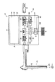
以下では、図面を参照して本発明の電子内視鏡装置10について説明する。図1は、本実施形態における電子内視鏡装置10のブロック図である。
【0013】
電子内視鏡装置10には、CCD11を有するビデオスコープ20と、CCD11から読み出される信号を処理するプロセッサ30とが備えられている。ビデオスコープ20は、プロセッサ30と着脱自在に接続される。
【0014】
ビデオスコープ20内にはライトガイド12が挿通されている。ライトガイド12は、光源部22から放射される光を伝達する光ファイバ束であり、ライトガイド入射端12Aと光源部22との間には、光源部22内の光源から放射される光束の光量を調節するための絞り(図示せず)や、光をライトガイド入射端12Aに集光させるための集光レンズ(図示せず)が設けられている。ビデオスコープ20がプロセッサ30に接続され、光源部22内の光源から光が放射されると、光はライトガイド入射端12Aに入射し、ビデオスコープ20側にあるライトガイド12の出射端12Bから出射する。そして、ライトガイド12から出射した光により、観察部位Sに光が照射される。
【0015】
観察部位Sで反射した光は、対物レンズ(図示せず)、カラーフィルタ(図示せず)を通ってCCD11の受光面に到達し、これにより観察部位Sの被写体像がCCD11の受光面に形成される。本実施形態においては、撮像方式として同時単板式が適用されており、CCD11の受光面上にはR、G、Bの色要素からなる原色のカラーフィルタ(図示せず)が配設されている。CCD11では、カラーフィルタを通る色に応じた被写体像の画像信号が光電変換により発生し、所定時間ごとに1フレームもしくは1フィールド分の画像信号が順次読み出される。ここではカラーテレビジョン方式としてNTSC方式が適用されており、1/30(1/60)秒間隔ごとに1フレーム(1フィールド)分の画像信号が順次読み出され、初段信号処理回路24へ送られる。
【0016】
初期信号処理回路24において、各色の1フレーム分のアナログ画素信号は、デジタル画像信号に変換される。さらに、デジタル画像信号にはホワイトバランス調整、γ補正などの処理が施されて、各色毎に画像メモリ25に格納される。デジタル画像信号は、カラーアナログビデオ信号(以下映像信号という)に変換され、映像信号が後段映像信号処理回路26へ送信される。映像信号は、後段映像信号処理回路26において出力レベルが調整されてからプリンタ36に送信され、この結果プリンタ36による被写体像の印刷が可能となる。なお、アナログ信号からデジタル信号への変換、デジタル信号からアナログ信号への変換、画像メモリ25への画素信号の取り込み等は、タイミングコントローラ28によって制御される。
【0017】
本発明による電子内視鏡装置においては、モニタ画面34を備えたモニタ32は、プロセッサ30と一体化されている。そして、モニタ32が一体化されたプロセッサ30は、その表面を構成する面のうち最も面積の広い1つの面(以下底面30Bという)あるいは底面30Bに隣接して直交する1つの面(以下側面30Sという)を下にして設置される。
【0018】
プロセッサ底面30Bには底面スイッチ40が設けられており、底面スイッチ40は、プロセッサ30がプロセッサ底面30Bを支持面として設置されたことを検出する。そして、この検出に基いて、プロセッサ底面30Bを下にしてプロセッサ30が設置されていること(以下底面設置という)を示す信号が、システムコントローラ21に送られる。同様に、プロセッサ30の側面30Sに設けられた側面スイッチ42は、プロセッサ30がプロセッサ側面30Sを支持面として設置されたことを検出し、この場合にはプロセッサ側面30Sを下にしてプロセッサ30が設置されていること(以下側面設置という)を示す信号が、システムコントローラ21に送られる。
【0019】
底面設置信号が検出されると、制御信号がシステムコントローラ21からLCD用信号処理回路27に送られる。この制御信号により、モニタ画面34のフレーム31を形成する辺のうち、底面30Bと平行な第1辺αの方向(いわゆる水平主走査方向・以下第1の方向という)を被写体像の左右方向とし、側面30Sと平行な第2辺βの方向(いわゆる垂直走査方向・以下第2の方向という)を被写体像の上下方向として被写体像をLCD(液晶ディスプレイ)であるモニタ画面34上に表示させることが定められる(この表示方法を以下では第1被写体像表示方法という)。
【0020】
一方、側面設置信号が検出されると、システムコントローラ21からLCD用信号処理回路27に送られる制御信号により、第1の方向を被写体像の上下方向とし、第2の方向を被写体像の左右方向として被写体像をモニタ画面34上に表示させることが定められる(この表示方法を以下では第2被写体像表示方法という)。
【0021】
本実施形態の電子内視鏡装置においては、文字や数字を含むキャラクタ情報は、一定の条件下で自動的に表示されたり、あるいはキーボード44による文字や数字の入力により表示される。キーボード44を用いて文字や数字が入力されると、システムコントローラ21によって定められている表示方法に従って、モニタ画面34上に文字や数字が表示される。
【0022】
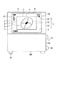
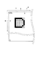
図2は、底面設置時に被写体像を表示するプロセッサ30の正面図である。
【0023】
本実施形態では、モニタ画面34を備えたモニタ32がプロセッサ30に開閉自在に一体化されており、図2では、モニタ32が開いた状態を示している。モニタ画面34のフレーム31内では、第1辺αと第2辺βを含むフレーム31と、被写体像を表示する被写体像表示領域33と、文字や数字を含むキャラクタ情報が表示される領域A〜Dのキャラクタ表示領域35とから構成されている。なお、被写体像表示領域33のフレームは矩形状であり、第1の方向と平行な辺(以下第3辺γという)と、第2の方向と平行な辺(以下第4辺εという)とに沿って画像が形成される。
【0024】
ここでは、プロセッサ30が底面設置されているため、観察部位Sの被写体像は、第1被写体像表示方法により被写体像表示領域33に表示されている。なお矢印Iの方向が上である。
【0025】
キャラクタ表示領域35の領域Aには、“NAME”“ID”等の文字が、領域Bには“DATE”“TIME”の文字が、領域Cには“COMMENT”の文字が表示され、一方、領域Dには文字が表示されていない。
【0026】
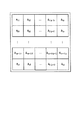
図3は、表示される被写体像を構成する画素の配列を概念的に示す図である。図4は、モニタ画面34を形成する画素のうち、被写体像表示領域33の表面に配列されている画素を概略的に示す図である。
【0027】
表示される被写体像を構成する画素は、X行×Y列のマトリクス状に配列されており、画像メモリ25では、各画素がデータとして所定のアドレスに格納されている。プロセッサ30が底面設置されていると検出され、第1被写体像表示方法による被写体像表示が選択されると、画像メモリ25に記録されている画素データが行ごとに順番に読み出される。すなわち、A11、A12、…A1(y―1)、A1yまで順番に読み出され、2行目のA21、A22…A2(y―1)、A2y、3行目のA31、…A3y…と順に読み出される。読み出しの順番決定は最も下の行まで進み、Axyが最後と定められる。こうして、A11からAxyまでの全ての画素データの読み出しの順番が定められ、この順番に従って、画素データはLCD用信号処理回路27に送信される。
【0028】
被写体像表示領域33における被写体像の表示は、LCD用信号処理回路27により、画像メモリ25に記録されている各画素データに対応する被写体像表示領域33の画素に対して、印加を調整することにより実施される。そして、被写体像表示領域33を形成するいずれの画素が、先述のいずれの画素データに対応して表示を行うかは、画素データの読み出しの順番に対応するように予め定められている。すなわち、最初の画素データによる表示は、底面設置時の被写体像表示領域33をオペレータから見た時に最も左上に位置する画素であるP1において実施され、2番目の信号による表示はP1に隣接するP2となり、3番目以下の信号には第3辺γに沿ってP2の右側に位置する画素が順次対応し、Y番目の画素データに基く表示は、右端の画素であるPyにて実施される。続いて、以下の画素データによる表示は、上から2行目の画素行に移り、P(y+1)以下、P(y+1)の右側に位置する画素にて順次行われる。各画素行の右端の画素の次には、そのすぐ下の行の最も左側に位置する画素が画素データに対応し、以下順次その行の右側の画素が各画素データに対応することとなる。なお、図3に示す画像メモリ25における概念的な画素配列と、被写体像表示領域33における画素配列との対応関係は、画素データの読み出しの順番によって決定される。すなわち、読み出しの順番が決まると、被写体像表示領域33の各画素において、それぞれに対応する画素データが定められることとなる。
【0029】
以上より、第1被写体像表示方法による被写体像表示が選択され、先述の順番で画素データが読み出された場合、画素データA11に基く表示は被写体像表示領域33の画素であるP1において実施され、以下画素データA12には画素P2、画素データA1(y―1)には画素P(y―1)、画素データA1yには画素Py、画素データA21には画素P(y+1)、読み出し順番が最後の画素データAxyにはP(xy)が、それぞれ対応して表示が行われることとなる。こうして全ての画素データについて、それぞれに対応する画素によって表示が行われ、全体として被写体像表示領域33上に観察部位Sの正立している被写体像が表示されることとなる。
【0030】
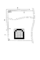
図5は、底面設置時のキャラクタ表示領域35における文字表示の一部を示す図である。
【0031】
キャラクタ表示領域35の領域Aの一部を概略的に示す図5においては、底面設置時の文字表示の例として、図2における文字のキャラクタ情報“ID”のうちの“D”を示している。ここで、矢印IIは右を示し、矢印IIIは下を示している。
プロセッサ30が底面設置されていると検出され、第1被写体像表示方法による被写体像表示が選択されると、システムコントローラ21に予め記録されているアルファベットの“D”を表示させるキャラクタ信号に基づいて、LCD用信号処理回路27により、図5に示す所定の位置にある画素に対する印加が調整されることにより、キャラクタ情報“D”が表示される。
【0032】
ここで、キャラクタ表示領域35を形成するいずれの画素が、いずれのキャラクタ信号に対応して表示を行うかは、キャラクタ信号の読み出しの順番によって定められる。すなわち、読み出しの順番が最初のキャラクタ信号による表示を行う画素がP’11であり、2番目の画素データに対応するのが画素P’12であり、以下全てのキャラクタ信号に対応する画素が定められているが、ここではアルファベットの“D”の表示に関する部分を中心に概略的に示されている。なお、キャラクタ表示領域35を形成する画素のうち、底面設置時に最も下の行の左端に位置する画素が、P’x1である。また、オペレータのキーボード44の操作により入力された文字や数字によるキャラクタ信号によっても、キャラクタ情報は同様に表示される。
【0033】
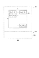
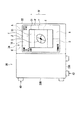
図6は、側面設置時に被写体像を表示するプロセッサ30の正面図である。
【0034】
ここでは、プロセッサ30が側面設置されているため、プロセッサ側面30S上に設けられた側面スイッチ42がその設置状態を検出しており、側面設置信号がシステムコントローラ21に送信される。従って、先述の第1被写体像表示方法による表示例(図2参照)と同様の映像信号に基く観察部位Sの被写体像が、第2被写体像表示方法により被写体像表示領域33に表示されている。なお、矢印IVは上を示している。
【0035】
本実施形態においては、モニタ画面34の被写体像表示領域33のフレームを形成する辺のうち、第3辺γが第4辺εよりも長く、第3辺γと平行な画素行を構成する画素数が、第4辺εと平行な画素列を構成する画素数よりも多い。従って、底面設置時に被写体像が映し出される基となった同じ映像信号に基いて、側面設置時に被写体像が映し出される場合には、完全に同一の被写体像を表示することはできない。
【0036】
そこで、本実施形態においては、システムコントローラ21によってプロセッサ30が側面設置されていると検出されると、同様の映像信号により底面設置時に表示される被写体像と同一の形状であってサイズのより小さい被写体像が、被写体像表示領域33内に表示されるように、映像信号に対する間引き処理が施される。このため、側面設置時の被写体像の表示は、被写体像表示領域33よりも小さく、被写体像表示領域33の相似形である側面設置時表示領域Eにて行われる。
【0037】
一方、キャラクタ表示領域35の領域Aには“DATE”“TIME”の文字が、領域Cには“NAME”“ID”等の文字が、領域Dには“COMMENT”の文字が表示されており、領域Bには文字は表示されていない。従って、先述の底面設置時(図2参照)と比較すると、同一の文字が表示される領域が異なっている。
【0038】
本実施形態においては、第1被写体像表示方法によりモニタ画面の所定の位置にキャラクタ情報が表示された場合と同一のキャラクタ情報が第2被写体像表示方法により表示される場合、その表示は、第1被写体像表示方法により表示された位置とモニタ画面34の中心との位置関係を、維持する位置においてなされる。この結果、キャラクタ情報と被写体像との位置関係や、複数の文字や数字からなるキャラクタ情報同士の位置関係は、側面設置時と底面設置時とで維持されることとなる(図6および図2参照)。
【0039】
図7は、表示される被写体像を構成する画素の配列を概念的に示す図である。図8は、モニタ画面34を形成する画素のうち、被写体像表示領域33の表面に配列されている画素を概略的に示す図である。
【0040】
先述のように、表示される被写体像を構成する画素は、X行×Y列のマトリクス状に配列されており、画像メモリ25では、各画素がデータとして所定のアドレスに格納されている。プロセッサ30が側面設置されていると検出され、第2被写体像表示方法による被写体像表示が選択されると、画像メモリ25に記録されている画像データが列ごとに順番に読み出される。すなわち、A1y、A2y、…A(x−1)y、Axyまで順番に読み出され、2列目のA1(y−1)、…Ax(y−1)、3列目のA1(y−2)、…Ax(y−2)、…と順に読み出される。読み出しの順番決定は最も左の列まで進み、Ax1が最後と定められる。こうして、A1yからAx1までの全ての映像信号の読み出しの順番が定められ、この順番に従って、映像信号はLCD用信号処理回路27に送信される。
【0041】
先述のように、被写体像表示領域33における被写体像の表示は、LCD用信号処理回路27により、画像メモリ25に記録されている各画素データに対応する被写体像表示領域33の画素に対して、印加を調整することにより実施される。そして、被写体像表示領域33を形成するいずれの画素が、先述のいずれの画素データに対応して表示を行うかは、画素データの読み出しの順番に対応するように予め定められている。すなわち、最初の映像信号による表示は、被写体像表示領域33を側面設置時にオペレータから見た時に最も右上に位置する画素であるP1において実施され、2番目の信号による表示はP1に隣接するP2となり、3番目以下の信号は第3辺γに沿ってP2の下側に位置する画素が順次対応し、Y番目の映像信号に基く表示は、最も下に位置する画素であるPyにて実施される。続いて、以下の画素データによる表示は、右から2列目の画素列に移り、P(y+1)以下、P(y+1)の下側に位置する画素にて順次行われる。各画素列の最も下に位置する画素の次には、その左隣の列の最も上に位置する画素が画素データに対応し、以下順次その列の下側の画素が各画素データに対応することとなる。
【0042】
以上より、第2被写体像表示方法による被写体像表示が選択され、先述の順番で映像信号が読み出された場合、画素データA1yに基く表示は被写体像表示領域33の画素であるP1において実施され、以下画素データA2yには画素P2、画素データA(x−1)yには画素P(y−1)、画素データAxyには画素Py、画素データA1(y−1)には画素P(y+1)がそれぞれ対応して、画素データA21には画素P(y+1)、読み出し順番が最後の画素データAx1にはP(xy)が、それぞれ対応して表示が行われることとなる。こうして、全ての画素データについて、それぞれに対応する画素によって表示が行われ、全体として被写体像表示領域33上に観察部位Sの正立している被写体像が表示されることとなる。なおこのように、同一の画素データを底面設置時とは異なる順番で読み出すことにより、底面設置時と実質上同一の被写体像が表示されている(図6および図2参照。先述の間引き処理により、被写体像のサイズは異なる)。
【0043】
図9は、側面設置時のキャラクタ表示領域35における文字表示の一部を示す図である。
【0044】
キャラクタ表示領域35の領域Cの一部を概略的に示す図9においては、側面設置時の文字表示の例として、図6における文字のキャラクタ情報“ID”のうちの“D”を示している。ここで矢印Vは下を示し、矢印VIは左を示している。プロセッサ30が側面設置されていると検出され、第2被写体像表示方法による被写体像表示が選択されると、システムコントローラ21に予め記録されているアルファベットの“D”を表示させるキャラクタ信号に基づいて、LCD用信号処理回路27により、図9に示す所定の位置にある画素に対する印加が調整されることにより、キャラクタ情報“D”が表示される。
【0045】
先述のように、キャラクタ表示領域35を形成するいずれの画素が、いずれのキャラクタ信号に対応して表示を行うかは、キャラクタ信号の読み出しの順番によって定められる。すなわち、読み出しの順番が最初のキャラクタ信号による表示を行う画素がP’11であり、2番目の画素データに対応するのが画素P’12である。ただし本実施形態においては、先述の底面設置時に表示された所定のキャラクタ情報とモニタ画面34の中心との位置関係が、側面設置時においても維持されるように、側面設置時のキャラクタ信号の読み出しの順番が底面設置時とは異なっている。このため、キャラクタ情報“D”が表示される位置が底面設置時とは異なり、キャラクタ情報“D”と観察部位Sの被写体像との位置関係や、キャラクタ情報“D”と他のキャラクタ情報との位置関係が維持されている(図6および図2参照)。
【0046】
なお、図7〜図9における画素データの読み出し、画素データに対応する被写体像表示領域33における画素の配列、キャラクタ表示領域35における画素の配列については、先述の間引き処理により、被写体像の表示に用いられない画像データおよび画素については考慮されていない。
【0047】
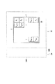
図10は、システムコントローラ21にて行われるプロセッサ30の設置面を検出するルーチンを示した図である。電子内視鏡装置10のメインスイッチが操作され、ONの状態となるとルーチンが開始される。
【0048】
ステップS801では、底面スイッチ40がONの状態であるか否かが検出される。底面スイッチ40がONの状態である、すなわちプロセッサ30が、底面設置されていると検出されると、ステップS802に進む。底面スイッチ40がONの状態でないと検出されると、ステップS805に進む。
【0049】
ステップS802では、側面スイッチ42がONの状態であるか否かが検出される。側面スイッチ42がONの状態であると検出されると、先にステップS801において底面設置されていると検出された結果と矛盾するため、ステップS803に進み、オペレータに設置状態の確認を促すエラーメッセージが表示されてルーチンは終了する。一方、側面スイッチ42がONの状態でないと検出されると、ステップS804に進む。ステップS804において、プロセッサ30が底面設置されていると検出されるため、底面設置時の表示が行われることとなり、ルーチンは終了する。
【0050】
ステップS805では、ステップS802と同様に、側面スイッチ42がONの状態であるか否かが検出される。側面スイッチ42がONの状態であると検出されると、ステップS806に進む。ステップS806において、プロセッサ30が側面設置されていると検出されるため、側面設置時の表示が行われることとなり、ルーチンは終了する。一方、側面スイッチ42がONの状態でないと検出されると、先にステップS801において底面設置されていないと検出された結果と矛盾するため、ステップS803に進み、オペレータに対する設置状態の確認を促す警告としてエラーメッセージが表示されてルーチンは終了する。
【0051】
以上のように、本実施形態においては、モニタ32がプロセッサ30と一体化され、設置面が選択可能な電子内視鏡装置10において、設置面を検出し、検出された設置面に応じて被写体像およびキャラクタ情報の表示が自動的に切替えられる。このためオペレータにとっては、同様の映像信号およびキャラクタ信号に基く被写体像およびキャラクタ情報は、プロセッサ30の設置面が異なる場合においても、実質上同一の被写体像およびキャラクタ情報として視認される。
【0052】
被写体像表示領域33においても文字や数字を含むキャラクタ情報を表示しても良いし、キャラクタ表示領域35にまで被写体像を拡大して表示しても良い。従って、キャラクタ情報が、被写体像表示領域33内でスーパーインポーズされても良い。
【0053】
映像信号に対する間引き処理は、モニタ画面34の被写体像表示領域33の第3辺γを構成する画素数と第4辺εを構成する画素数とが、同一の場合には不要である。また本実施形態と異なり、第3辺γと平行な画素配列を構成する画素数が、第4辺εと平行な画素配列を構成する画素数よりも少ない場合、側面設置時ではなく、底面設置時に間引き処理が実施されるように設定されても良い。
【0054】
本発明の実施形態として電子内視鏡装置10について説明したが、デジタルカメラ、デジタルビデオカメラ、表示機能付き携帯電話などの撮像機器や、ノート型パーソナルコンピュータなどの一体型モニタを備えた電子機器に本発明を適用しても良い。これらが設置面の上や三脚上に設置されず、オペレータの手によって支持されながら使用される場合、オペレータが、被写体像やキャラクタ情報の表示方向を切替えスイッチにより選択しても良い。
【0055】
モニタ画面34は、LCDに限定されず、CRT(ディスプレイ管)、エレクトロルミネッセントディスプレイ、プラズマディスプレイ等のいずれであっても良い。
【0056】
プロセッサ30の設置面は、底面スイッチ40および側面スイッチ42により検出されるのではなく、メニュー表示を設けてオペレータに指定させることにより、検出されても良い。
【0057】
底面スイッチ40および側面スイッチ42は、圧力を検出するスイッチではなく、自動的にプロセッサ30の設置方向を検出する角度スイッチであっても良い。
【0058】
オペレータにプロセッサ30の設置状態の確認を促す警告は、第2被写体像表示方法によりモニタ画面34上にメッセージ表示されても良いし、音声により報知させても良い。
【0059】
【発明の効果】
以上のように本発明によれば、表示装置がプロセッサと一体化された電子内視鏡装置等の、表示装置一体型の撮像機器を有効に活用するための、画面表示の制御が可能となる。
【図面の簡単な説明】
【図1】本発明における電子内視鏡装置のブロック図である。
【図2】底面設置されているプロセッサの正面図である。
【図3】表示される被写体像を構成する画素の配列を概念的に示す図である。
【図4】底面設置時におけるモニタ画面表面の画素配列を概略的に示す図である。
【図5】底面設置時のキャラクタ表示領域における文字表示の一部を示す図である。
【図6】側面設置されているプロセッサの正面図である。
【図7】表示される被写体像を構成する画素の配列を概念的に示す図である。
【図8】側面設置時における、モニタ画面表面の画素配列を概略的に示す図である。
【図9】側面設置時のキャラクタ表示領域における文字表示の一部を示す図である。
【図10】プロセッサの設置面を検出するルーチンを示した図である。
【符号の説明】
10 電子内視鏡装置
11 CCD(撮像素子)
20 ビデオスコープ
21 システムコントローラ(支持面検出手段)
25 画像メモリ
26 後段映像信号処理回路
27 LCD用信号処理回路(第1・第2被写体像表示手段)
28 タイミングコントローラ
30 プロセッサ
30B プロセッサ底面(第1の面・支持面)
30S プロセッサ側面(第2の面・支持面)
31 モニタ画面のフレーム(画像形成フレーム)
32 モニタ
33 被写体像表示領域
34 モニタ画面(画像形成部)
35 キャラクタ表示領域
40 底面スイッチ(支持面検出手段)
42 側面スイッチ(支持面検出手段)
α モニタ画面フレームの第1辺
β モニタ画面フレームの第2辺
γ 被写体像表示領域フレームの第3辺
ε 被写体像表示領域フレームの第4辺[0001]
BACKGROUND OF THE INVENTION
The present invention relates to screen display control of subject images and character information in imaging devices such as electronic endoscope devices and video cameras, and devices with a display device such as a mobile phone.
[0002]
[Prior art]
A conventional electronic endoscope apparatus includes a video scope that is inserted into the body, a processor that performs signal processing, and a monitor that displays an observation site. Then, based on a signal transmitted from the processor via the cable, an image of the observation site is displayed on the monitor screen. At this time, with respect to the screen display, display control is performed in the processor in order to display the subject image in a predetermined area and to display character information such as the name of the patient being observed.
[0003]
[Problems to be solved by the invention]
Since the monitor and the processor are installed independently, the space required for installation and use of the electronic endoscope device increases, which takes time for installation and reduces the overall operation efficiency of the endoscope. It was. In addition, other electronic devices with a display function are not always capable of screen display according to the usage status.
[0004]
Therefore, in the present invention, the necessary space is reduced to improve the convenience of the electronic endoscope device, and the electronic endoscope device and other display devices can be displayed on the screen according to the usage situation. An object is to provide a control method.
[0005]
[Means for Solving the Problems]
The processor of the electronic endoscope apparatus according to the present invention is a surface of the processor, and is substantially perpendicular to the first surface and a first surface supported as necessary on a substantially horizontal installation surface. And a second surface supported by the installation surface as necessary. And it is provided with the support surface detection means which detects which surface is supported among the 1st surface and the 2nd surface, The 1st direction and 2nd which are substantially parallel to the 1st surface An image forming unit for defining an image forming frame along a second direction substantially parallel to the surface;
[0006]
When the first surface is supported, the first subject image display means defines the first direction as the left-right direction of the subject image and the second direction as the up-down direction of the subject image, and the video scope The first subject image that is upright according to the image to be viewed, based on the image signal read out by the image sensor, is displayed on the image forming unit. Here, the erect subject image means a subject image that is not reversed horizontally and vertically according to a visually perceived image. When the second surface is supported, the second subject image display means defines the second direction as the left-right direction of the subject image and the first direction as the up-down direction of the subject image, and the imaging element. The second subject image erecting according to the image to be viewed, based on the image signal read out by the above, is displayed on the image forming unit.
[0007]
When the same subject is displayed as the first subject image and the second subject image on the image forming unit by the first subject image display unit and the second subject image display unit, respectively, the image is the same in any case. For the operator facing the forming unit, the first subject image and the second subject image are observed as being substantially the same.
[0008]
For example, the first subject image display means displays the first subject image according to the video signal based on the pixel signal read from the image sensor, and the second subject image display means performs the first thinning process on the video signal by performing the thinning process on the video signal. A second subject image smaller in size than the one subject image is displayed.
[0009]
The first subject image display means and the second subject image display means are preferably capable of further displaying character information including letters and numbers. Based on the character signal, the first subject image display means displays the first character information at a predetermined position of the image forming unit, while the second subject image display means displays the center of the first character information image forming unit. More preferably, the second character information is displayed at a predetermined position that maintains the positional relationship with respect to. If only the display direction of the character information including letters and numbers is changed between the side surface installation and the bottom surface installation, and the display position is the same on the
[0010]
The processor of the electronic endoscope apparatus according to the present invention preferably has notifying means for notifying an operator of an abnormality in installation when a supported surface of the first surface and the second surface is not detected. .
[0011]
The electronic device with a display function of the present invention includes an image forming unit that defines an image forming frame along a first direction and a second direction orthogonal to each other. Then, the first direction is defined as the left-right direction of the subject image, the second direction is defined as the up-down direction of the subject image, and the first subject image display that displays the upright first subject image on the image forming unit And a second subject image that displays the upright second subject image on the image forming unit by defining the second direction as the left-right direction of the subject image and the first direction as the up-down direction of the subject image. Display means. The first subject image display means and the second subject image display means can be switched by an operator's operation or automatically.
[0012]
DETAILED DESCRIPTION OF THE INVENTION
Below, the
[0013]
The
[0014]
A
[0015]
The light reflected by the observation region S passes through an objective lens (not shown) and a color filter (not shown) and reaches the light receiving surface of the CCD 11, thereby forming a subject image of the observation region S on the light receiving surface of the CCD 11. Is done. In this embodiment, a simultaneous single plate type is applied as an imaging method, and a primary color filter (not shown) composed of R, G, and B color elements is disposed on the light receiving surface of the CCD 11. . In the CCD 11, an image signal of a subject image corresponding to a color passing through a color filter is generated by photoelectric conversion, and image signals for one frame or one field are sequentially read at predetermined time intervals. Here, the NTSC system is applied as the color television system, and image signals for one frame (one field) are sequentially read out every 1/30 (1/60) second interval and sent to the first stage
[0016]
In the initial
[0017]
In the electronic endoscope apparatus according to the present invention, the
[0018]
A
[0019]
When the bottom installation signal is detected, a control signal is sent from the
[0020]
On the other hand, when the side surface setting signal is detected, the first direction is set as the vertical direction of the subject image and the second direction is set as the horizontal direction of the subject image by the control signal sent from the
[0021]
In the electronic endoscope apparatus of the present embodiment, character information including letters and numbers is automatically displayed under certain conditions, or is displayed by inputting letters and numbers using the keyboard 44. When characters and numbers are input using the keyboard 44, the characters and numbers are displayed on the
[0022]
FIG. 2 is a front view of the
[0023]
In the present embodiment, a
[0024]
Here, since the
[0025]
Characters such as “NAME” and “ID” are displayed in the area A of the
[0026]
FIG. 3 is a diagram conceptually showing the arrangement of pixels constituting the displayed subject image. FIG. 4 is a diagram schematically showing pixels arranged on the surface of the subject
[0027]
The pixels constituting the displayed subject image are arranged in a matrix of X rows × Y columns. In the
[0028]
The display of the subject image in the subject
[0029]
As described above, when the subject image display by the first subject image display method is selected and the pixel data is read out in the order described above, the pixel data A 11 The display based on P is a pixel of the subject
[0030]
FIG. 5 is a diagram showing a part of the character display in the
[0031]
In FIG. 5 schematically showing a part of the area A of the
When it is detected that the
[0032]
Here, which pixel forming the
[0033]
FIG. 6 is a front view of the
[0034]
Here, since the
[0035]
In the present embodiment, among the sides forming the frame of the subject
[0036]
Therefore, in the present embodiment, if the
[0037]
On the other hand, characters “DATE” and “TIME” are displayed in the area A of the
[0038]
In the present embodiment, when the same character information is displayed by the second subject image display method as when the character information is displayed at a predetermined position on the monitor screen by the first subject image display method, the display is The position relationship between the position displayed by the one subject image display method and the center of the
[0039]
FIG. 7 is a diagram conceptually showing the arrangement of pixels constituting the displayed subject image. FIG. 8 is a diagram schematically showing pixels arranged on the surface of the subject
[0040]
As described above, the pixels constituting the displayed subject image are arranged in a matrix of X rows and Y columns, and in the
[0041]
As described above, the display of the subject image in the subject
[0042]
As described above, when the subject image display by the second subject image display method is selected and the video signal is read out in the order described above, the pixel data A 1y The display based on P is a pixel of the subject
[0043]
FIG. 9 is a diagram showing a part of the character display in the
[0044]
In FIG. 9 schematically showing a part of the area C of the
[0045]
As described above, which pixel forming the
[0046]
It should be noted that the pixel data reading, the pixel arrangement in the subject
[0047]
FIG. 10 is a diagram showing a routine for detecting the installation surface of the
[0048]
In step S801, it is detected whether or not the
[0049]
In step S802, it is detected whether or not the
[0050]
In step S805, as in step S802, it is detected whether or not the
[0051]
As described above, in the present embodiment, the
[0052]
Character information including letters and numbers may also be displayed in the subject
[0053]
The thinning process for the video signal is unnecessary when the number of pixels constituting the third side γ and the number of pixels constituting the fourth side ε of the subject
[0054]
The
[0055]
The
[0056]
The installation surface of the
[0057]
The
[0058]
The warning prompting the operator to confirm the installation state of the
[0059]
【The invention's effect】
As described above, according to the present invention, it is possible to control screen display in order to effectively use an imaging apparatus integrated with a display device such as an electronic endoscope device in which the display device is integrated with a processor. .
[Brief description of the drawings]
FIG. 1 is a block diagram of an electronic endoscope apparatus according to the present invention.
FIG. 2 is a front view of a processor installed on a bottom surface;
FIG. 3 is a diagram conceptually illustrating an arrangement of pixels constituting a displayed subject image.
FIG. 4 is a diagram schematically showing a pixel arrangement on the surface of a monitor screen when a bottom surface is installed.
FIG. 5 is a diagram showing a part of character display in a character display area when the bottom surface is installed.
FIG. 6 is a front view of a processor installed on a side surface;
FIG. 7 is a diagram conceptually illustrating an arrangement of pixels constituting a displayed subject image.
FIG. 8 is a diagram schematically showing a pixel arrangement on the surface of a monitor screen when a side surface is installed.
FIG. 9 is a diagram showing a part of the character display in the character display area at the time of side installation.
FIG. 10 is a diagram showing a routine for detecting the installation surface of the processor.
[Explanation of symbols]
10 Electronic endoscope device
11 CCD (imaging device)
20 Videoscope
21 System controller (support surface detection means)
25 Image memory
26 Post-stage video signal processing circuit
27 LCD signal processing circuit (first and second subject image display means)
28 Timing controller
30 processor
30B Processor bottom surface (first surface / support surface)
30S processor side (second surface / support surface)
31 Monitor screen frame (image formation frame)
32 monitors
33 Subject image display area
34 Monitor screen (image forming unit)
35 Character display area
40 Bottom switch (support surface detection means)
42 Side switch (support surface detection means)
α First side of monitor screen frame
β Second side of monitor screen frame
γ 3rd side of subject image display area frame
ε Fourth side of subject image display area frame
Claims (6)
前記第1の面に略垂直であって前記設置面に支持されるための第2の面と、
前記第1の面および前記第2の面のうち支持されている面を検出する支持面検出手段と、
前記第1の面に略平行な第1の方向および前記第2の面に略平行な第2の方向に沿って画像形成フレームを規定する画像形成部と、
前記第1の面が支持されている場合、前記第1の方向を被写体像の左右方向、前記第2の方向を被写体像の上下方向に規定し、ビデオスコープの撮像素子から読み出される画素信号に基いた映像信号に応じて、視覚される像に応じて正立している第1の被写体像を前記画像形成部に表示する第1被写体像表示手段と、
前記第2の面が支持されている場合、前記第2の方向を被写体像の左右方向、前記第1の方向を被写体像の上下方向に規定し、ビデオスコープの撮像素子から読み出される画素信号に基いた映像信号に応じて、視覚される像に応じて正立している第2の被写体像を前記画像形成部に表示する第2被写体像表示手段とを備えることを特徴とする電子内視鏡装置のプロセッサ。A first surface to be supported on a surface of the processor, the mounting surface being substantially horizontal;
A second surface that is substantially perpendicular to the first surface and is supported by the installation surface;
A supporting surface detecting means for detecting a surface that is supported among the first surface and the second surface;
An image forming section for defining an image forming frame along a first direction substantially parallel to the first surface and a second direction substantially parallel to the second surface;
When the first surface is supported, the first direction is defined as the left-right direction of the subject image, and the second direction is defined as the up-down direction of the subject image. First subject image display means for displaying on the image forming unit a first subject image erecting according to a visual image in accordance with a video signal based thereon;
When the second surface is supported, the second direction is defined as the left-right direction of the subject image, the first direction is defined as the up-down direction of the subject image, and the pixel signal read from the imaging device of the videoscope And a second subject image display means for displaying on the image forming unit a second subject image that stands upright according to a visual image in accordance with a video signal based thereon. Mirror device processor.
前記第1被写体像表示手段が、キャラクタ信号に基いて前記画像形成部の所定の位置に第1キャラクタ情報を表示し、
前記第2被写体像表示手段が、キャラクタ信号に基いて前記第1キャラクタ情報の前記画像形成部の中心に対する位置関係を維持するように所定の位置に第2キャラクタ情報を表示することを特徴とする請求項1に記載の電子内視鏡装置のプロセッサ。The first subject image display means and the second subject image display means can further display character information,
The first subject image display means displays first character information at a predetermined position of the image forming unit based on a character signal;
The second subject image display means displays second character information at a predetermined position so as to maintain the positional relationship of the first character information with respect to the center of the image forming unit based on a character signal. The processor of the electronic endoscope apparatus according to claim 1.
前記第1の方向を被写体像の左右方向、前記第2の方向を被写体像の上下方向に規定し、正立している第1の被写体像を前記画像形成部に表示する第1被写体像表示手段と、
前記第2の方向を被写体像の左右方向、前記第1の方向を被写体像の上下方向に規定し、正立している第2の被写体像を前記画像形成部に表示する第2被写体像表示手段とを備え、
前記第1被写体像表示手段と前記第2被写体像表示手段とが切替え可能であることを特徴とする表示機能付き電子機器。An image forming unit defining an image forming frame along a first direction and a second direction substantially orthogonal to each other;
A first subject image display in which the first direction is defined as the left-right direction of the subject image, the second direction is defined as the up-down direction of the subject image, and the upright first subject image is displayed on the image forming unit. Means,
A second subject image display in which the second direction is defined as the left-right direction of the subject image, the first direction is defined as the up-down direction of the subject image, and the upright second subject image is displayed on the image forming unit. Means and
An electronic device with a display function, wherein the first subject image display means and the second subject image display means can be switched.
Priority Applications (1)
| Application Number | Priority Date | Filing Date | Title |
|---|---|---|---|
| JP2003209726A JP2005073721A (en) | 2003-08-29 | 2003-08-29 | Electronic endoscope device with integrated display |
Applications Claiming Priority (1)
| Application Number | Priority Date | Filing Date | Title |
|---|---|---|---|
| JP2003209726A JP2005073721A (en) | 2003-08-29 | 2003-08-29 | Electronic endoscope device with integrated display |
Publications (1)
| Publication Number | Publication Date |
|---|---|
| JP2005073721A true JP2005073721A (en) | 2005-03-24 |
Family
ID=34402558
Family Applications (1)
| Application Number | Title | Priority Date | Filing Date |
|---|---|---|---|
| JP2003209726A Withdrawn JP2005073721A (en) | 2003-08-29 | 2003-08-29 | Electronic endoscope device with integrated display |
Country Status (1)
| Country | Link |
|---|---|
| JP (1) | JP2005073721A (en) |
Cited By (1)
| Publication number | Priority date | Publication date | Assignee | Title |
|---|---|---|---|---|
| JP5851647B2 (en) * | 2013-07-05 | 2016-02-03 | オリンパス株式会社 | Monitor device |
-
2003
- 2003-08-29 JP JP2003209726A patent/JP2005073721A/en not_active Withdrawn
Cited By (2)
| Publication number | Priority date | Publication date | Assignee | Title |
|---|---|---|---|---|
| JP5851647B2 (en) * | 2013-07-05 | 2016-02-03 | オリンパス株式会社 | Monitor device |
| US9795277B2 (en) | 2013-07-05 | 2017-10-24 | Olympus Corporation | Monitor apparatus |
Similar Documents
| Publication | Publication Date | Title |
|---|---|---|
| JP4597871B2 (en) | Digital camera | |
| CN100438571C (en) | Imaging system | |
| US8036482B2 (en) | Image processing apparatus and method, program, and recording medium | |
| US20010048413A1 (en) | Display device, method of adjusting a display device, and a cellular phone | |
| EP3076653A1 (en) | Display device and shooting display method therefor | |
| JP2012186670A (en) | Imaging device, imaging method, and imaging program | |
| US20140313329A1 (en) | Live panning system and method | |
| CN1998229B (en) | Imaging device that can operate in multiple aspect ratios | |
| JP2019186728A (en) | Electronic device, control method therefor, program, and storage medium | |
| US11972742B2 (en) | Display apparatus, photoelectric conversion apparatus, electronic equipment, and wearable device | |
| US20080316329A1 (en) | Camera module | |
| US20090079858A1 (en) | Image display device | |
| JP2005073721A (en) | Electronic endoscope device with integrated display | |
| JP2006060496A (en) | Image display device | |
| JP2009212757A (en) | Image display system | |
| WO2014109129A1 (en) | Display control device, program, and display control method | |
| KR100916895B1 (en) | Video display device | |
| KR101147327B1 (en) | Camera module and surveillance apparatus having the same | |
| JP2013145949A (en) | Projection system, and alignment adjusting method for superposed image | |
| CN101347001A (en) | Method and apparatus for correcting misalignment of a lenticular in a 3-D television receiver | |
| KR20110020521A (en) | Digital camera | |
| US9978122B2 (en) | Electronic endoscope | |
| JP2007049615A (en) | Pixel shift adjustment method, image display device, and program for realizing pixel shift adjustment method | |
| US20060221200A1 (en) | Display device and portable imaging device | |
| JP4811249B2 (en) | Remote indication system |
Legal Events
| Date | Code | Title | Description |
|---|---|---|---|
| A621 | Written request for application examination |
Free format text: JAPANESE INTERMEDIATE CODE: A621 Effective date: 20060706 |
|
| A711 | Notification of change in applicant |
Free format text: JAPANESE INTERMEDIATE CODE: A712 Effective date: 20080501 |
|
| A977 | Report on retrieval |
Free format text: JAPANESE INTERMEDIATE CODE: A971007 Effective date: 20090617 |
|
| A131 | Notification of reasons for refusal |
Free format text: JAPANESE INTERMEDIATE CODE: A131 Effective date: 20090623 |
|
| A761 | Written withdrawal of application |
Free format text: JAPANESE INTERMEDIATE CODE: A761 Effective date: 20090824 |