JP2005073714A - Flexion-type joint contracture treatment device - Google Patents
Flexion-type joint contracture treatment device Download PDFInfo
- Publication number
- JP2005073714A JP2005073714A JP2003209589A JP2003209589A JP2005073714A JP 2005073714 A JP2005073714 A JP 2005073714A JP 2003209589 A JP2003209589 A JP 2003209589A JP 2003209589 A JP2003209589 A JP 2003209589A JP 2005073714 A JP2005073714 A JP 2005073714A
- Authority
- JP
- Japan
- Prior art keywords
- movable body
- connecting member
- base
- actuator
- guide surface
- Prior art date
- Legal status (The legal status is an assumption and is not a legal conclusion. Google has not performed a legal analysis and makes no representation as to the accuracy of the status listed.)
- Pending
Links
Images
Landscapes
- Rehabilitation Tools (AREA)
Abstract
【課題】本発明は、関節部分に対して安定した屈曲力を長時間加えることができる屈伸型関節拘縮治療装置を得ることを目的とするものである。
【解決手段】近位部2には、ベース4が装着されている。遠位部3には、可動体5が装着されている。ベース4には、エアシリンダ14が搭載されている。エアシリンダ14と可動体5との間には、中間連結板16が連結されている。可動体5及びエアシリンダ14と中間連結板16との間には、第1及び第2トーションばね19が配置されている。エアシリンダ14により中間連結板16をガイド面8aに沿って移動させることによって、第1及び第2トーションばね19,20により関節部分1に所定の屈曲力が加えられる。
【選択図】 図1An object of the present invention is to provide a bending-extension-type joint contracture treatment apparatus that can apply a stable bending force to a joint portion for a long time.
A proximal portion is attached with a base. A movable body 5 is attached to the distal portion 3. An air cylinder 14 is mounted on the base 4. An intermediate connecting plate 16 is connected between the air cylinder 14 and the movable body 5. Between the movable body 5 and the air cylinder 14 and the intermediate connecting plate 16, first and second torsion springs 19 are arranged. By moving the intermediate connecting plate 16 along the guide surface 8 a by the air cylinder 14, a predetermined bending force is applied to the joint portion 1 by the first and second torsion springs 19 and 20.
[Selection] Figure 1
Description
【0001】
【発明の属する技術分野】
この発明は、人体の関節部分に屈曲・伸展力を加えることにより関節拘縮を治療するために用いられる屈伸型関節拘縮治療装置に関するものである。
【0002】
【従来の技術】
従来、例えば外傷、手術、固定又は廃用性症候群等の原因により、人体の関節部分に拘縮が生じた場合、主に徒手による治療が施されていた。また、電動機の駆動力により関節部分を屈曲・伸展させるCPM装置(持続的他動運動装置)が用いられることもあった(例えば、特許文献1参照)。
【0003】
【特許文献1】
特開平8−687号公報
【0004】
【発明が解決しようとする課題】
しかし、拘縮が生じた関節部分の可動域を拡大するためには、対象となる関節部分に「痛みを感じない程度の一定の弱い外力を長時間加え続ける」、「1〜2時間に1度は外力を抜いて、関節液潤滑を促すために関節運動を行う」という治療手法を数週間に渡って実施することが有効であり、かつ患者への痛み等の負担が少ないことがわかっている。しかし、従来の徒手による屈曲・伸展では、力の加減は可能であるが、長時間に渡って安定して力を加え続けることは困難であった。
また、従来のCPM装置では、関節可動域を維持することは可能であるが、拘縮改善効果はなく、弱い屈曲・伸展力を長時間加えることはできず、また力の調整も容易でなかった。
【0005】
この発明は、上記のような問題点を解決することを課題としてなされたものであり、関節に対して安定した外力を長時間加えることができる屈伸型関節拘縮治療装置を得ることを目的とする。
【0006】
【課題を解決するための手段】
この発明に係る屈伸型関節拘縮治療装置は、治療対象となる関節部分の両側に位置する人体の近位部及び遠位部のうち近位部に装着され、ガイド面を有しているベース、遠位部に装着される可動体、ベースに搭載されているアクチュエータ、可動体及びアクチュエータの間に可動体及びアクチュエータに対してそれぞれ廻旋出来るように連結され、アクチュエータの駆動によりガイド面に沿って移動する連結部材、及び可動体及びアクチュエータの少なくともいずれか一方と連結部材との間に設けられ、関節部分を屈曲・伸展させる方向へ可動体及び連結部材の少なくともいずれか一方を動かす手段を備え、連結部材がベースに沿って可動体側へ移動することにより、関節部分を屈曲・伸展させる方向へ可動体及び連結部材がベースに対して廻旋されるものである。
【0007】
【発明の実施の形態】
以下、この発明の実施の形態を図について説明する。
実施の形態1.
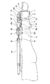
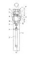
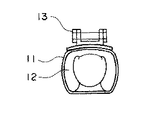
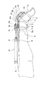
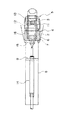
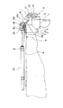
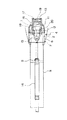
図1はこの発明の実施の形態1による屈伸型関節拘縮治療装置の主要部を示す側面図、図2は図1の屈伸型関節拘縮治療装置を示す平面図、図3は図1の屈伸型関節拘縮治療装置を示す横断面図、図4は図1の屈伸型関節拘縮治療装置により関節部分を屈曲させた状態を示す側面図、図5は図4の屈伸型関節拘縮治療装置を示す平面図、図6は図1の屈伸型関節拘縮治療装置により、関節部分をさらに大きく屈曲させた状態を示す側面図、図7は図6の屈伸型関節拘縮治療装置を示す平面図である。
【0008】
実施の形態1では、人体の手指関節部分(近位指節関節)1を治療対象とする屈伸型関節拘縮治療装置を示している。また、関節部分1を挟んで隣接する手指部分を近位部2及び遠位部3としている。近位部2には、ベース4が装着されている。遠位部3には、関節部分1を屈曲する方向へベース4に対して移動可能な可動体5が装着されている。
【0009】
ベース4は、近位部2が挿入される円筒状のベース側保持(ストラップ)部6と、ベース側保持部6の内側に設けられた膨張収縮体としての第1エアバッグ7と、ベース側保持部6に固定された支持板8と、支持板8に固定されたシリンダ取付板9とを有している。支持板8には、ガイド面8aが設けられている。支持板8の可動体5側の端部には、ガイド面8aに対して傾斜したベース端傾斜面8bが設けられている。
【0010】
可動体5は、遠位部3が挿入される円筒状の可動体側保持(ストラップ)部11と、可動体側保持部11の内側に設けられた膨張収縮体としての第2エアバッグ12と、可動体側保持部11に連結された可動体連結板13とを有している。
【0011】
第1エアバッグ7は、ベース側保持部6と近位部2との間に介在し、第2エアバッグ12は、可動体側保持部11と遠位部3との間に介在する。第1及び第2エアバッグ7,12は、流体である空気が供給されることにより膨張して近位部2及び遠位部3への拘束力を強め、空気が排出されることにより収縮して拘束力を弱める。
【0012】
シリンダ取付板9には、流体圧式アクチュエータ(空気圧式アクチュエータ)としてのエアシリンダ14のアウタパイプが固定されている。エアシリンダ14のインナロッドは、シリンダ連結板15に接続されている。エアシリンダ14は、流体である空気の圧力を利用して駆動力を発生する。
【0013】
可動体連結板13とシリンダ連結板15との間には、連結部材である中間連結板16が連結されている。中間連結板16は、可動体連結板13に第1軸17を中心として廻旋出来るように連結されている。また、中間連結板16は、シリンダ連結板15に第2軸18を中心として廻旋出来るように連結されている。
【0014】
可動体5と中間連結板16との間、即ち第1軸17には、関節部分1を屈曲させる方向(図の時計方向)へ中間連結板16に対して可動体5を動かす手段としての第1トーションばね19が設けられている。エアシリンダ14と中間連結板16との間、即ち第2軸18には、関節部分1を屈曲させる方向(図の時計方向)へシリンダ連結板15に対して中間連結板16を動かす手段としての第2トーションばね20が設けられている。
【0015】
中間連結板16のガイド面8aとの摺動面16aは、中間連結板16の移動に伴い中間連結板16を徐々に廻旋するようにガイド面8aに対して傾斜している。これにより、中間連結板16の厚さ寸法は、可動体5側からエアシリンダ14側へ向けて徐々に小さくなっている。
【0016】
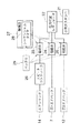
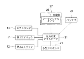
図8は図1のエアシリンダ14及びエアバッグ7,12の制御システムを示すブロック図である。この制御システムは、小形軽量のポータブルタイプとして構成されている。流体供給装置としての小形ガスボンベ21内に圧縮され収容された空気は、圧力可変レギュレータ22、電磁弁23〜25を介してエアシリンダ14及びエアバッグ7,12に供給される。
【0017】
エアシリンダ14の駆動力、及びエアバッグ7,12による拘束力は、圧力可変レギュレータ22を調節することにより設定される。電磁弁23とエアシリンダ14との間には、空気流量を制限することによりエアシリンダ14の動作速度を調整するスピードコントローラ26が設けられている。
【0018】
エアシリンダ14及びエアバッグ7,12への空気の供給・排出のタイミングを制御する制御部27は、シーケンシャルタイマ28を有している。電磁弁23〜25は、シーケンシャルタイマ28で予め設定された動作プログラムに基づき、シーケンシャルタイマ28からの指令に応じて開閉動作(加圧・保持・開放)する。
【0019】
電磁弁23〜25及びシーケンシャルタイマ28への電力の供給は、バッテリ29により行われる。バッテリ29としては、例えば乾電池、充電池又は太陽電池等を使用することができる。
【0020】
次に、動作について説明する。使用者がベース側保持部6に近位部2を挿入し、可動体側保持部11に遠位部3を挿入する。図1に示すように、エアシリンダ14のインナロッドが引っ込んだ状態では、可動体連結板13及び中間連結板16は、ガイド面8aに接しているため、一直線上に整列されており、トーションばね19,20が短縮した状態である。このため、可動体側保持部11は、ベース側保持部6に対してほぼ同軸上に配置されている。
【0021】
図1の状態でベース側保持部6及び可動体側保持部11に手指を挿入するためには、手指を真っ直ぐに伸ばす必要がある。従って、拘縮等のために手指を伸ばすのが困難な場合には、エアシリンダ14のインナロッドを少しだけ突出させ、例えば図4に示すように、ベース側保持部11に対して可動体側保持部11をある程度屈曲させておいてもよい。
【0022】
このような近位部2及び遠位部3への装着の後、制御部27の動作プログラムをスタートさせることにより、まず第1及び第2エアバッグ7,12に空気が供給され、近位部2及び遠位部3に対する拘束力が強められ、ベース側保持部6及び可動体側保持部11の位置ずれが防止される。第1及び第2エアバッグ7,12による拘束力が予め設定された力に達すると、第1及び第2エアバッグ7,12への空気の供給が停止され、以後はその拘束力が維持される。
【0023】
この後、エアシリンダ14のアウタパイプ内に空気が供給される。これにより、エアシリンダ14のインナロッドがアウタパイプから突出する方向へ押し出され、可動体連結板13、シリンダ連結板15及び中間連結板16がガイド面8aに沿って移動する。
【0024】
そして、まず可動体連結板13が支持板8のベース端傾斜面8bに達すると、第1トーションばね19のばね力が加わり始め、可動体連結板13が中間連結板16に対して徐々に廻旋され、可動体5がベース4に対して徐々に屈曲される。この後、さらに中間連結板16が移動すると、中間連結板16の摺動面16aがガイド面8aに対して傾斜していることにより、第2トーションばね20のばね力が徐々に加わり、中間連結板16がシリンダ連結板15に対して徐々に廻旋され、可動体5がベース4に対してさらに屈曲されていく。
【0025】
シリンダ連結板15がガイド面8aの端部まで移動すると、エアシリンダ14への空気の供給が停止され、図6に示すように、関節部分1の屈曲状態が維持される。
【0026】
また、エアシリンダ14のインナロッドを後退させることにより、シリンダ連結板15はガイド面8aに沿ってシリンダ取付板9側へ移動する。これにより、可動体連結板13及び中間連結板16が屈曲動作時とは逆に動作し、関節部分1の屈曲が解除(関節部分1が伸張)される。
【0027】
エアシリンダ14に対する空気の供給・排出は、シーケンシャルタイマ28で予め設定された動作プログラムに従って行われる。例えば、関節部分1に対して1時間継続して屈曲力を加えた後、5分間屈曲力を解除するという動作が繰り返して行われる。屈曲力を解除した休止時間においては、エアバッグ7,12内の空気も排出され、拘束力が解除される。
【0028】
このような屈伸型関節拘縮治療装置によれば、エアシリンダ14により中間連結板16をガイド面8aに沿って移動することによって、第1及び第2トーションばね19,20により関節部分1に所定の屈曲力が加えられるようにしたので、関節部分1に対して安定した屈曲力を長時間加えることができる。従って、関節部分1に「痛みを感じない程度の一定の弱い外力を長時間加え続ける」ことができる。また、「1〜2時間に1度は外力を抜いて関節を動かす」こともできる。このため、関節部分1の関節軟骨の二次的な損傷を防止しつつ、関節部分1の可動域を拡大する治療を行うことができる。
【0029】
さらに、アクチュエータとして流体圧式アクチュエータを用いたので、より容易に、一定の弱い屈曲力を長時間加え続けることが可能となる。また、流体の圧力を減圧することにより、屈曲力の定期的な解除も容易である。
さらに、流体圧式アクチュエータとしてエアシリンダ14を用いたので、構造の簡素化及び軽量化を図ることができる。さらにまた、電動モータとギアを用いる場合に比べて、衝撃力に対する耐久性が大で、機構が破損することが少なく、軽量であるとともに耐水性もあって、日常生活の中での使用が容易である。
【0030】
また、支持板8には、ガイド面8aが設けられており、支持板8の可動体5側の端部には、ガイド面8aに対して傾斜したベース端傾斜面8bが設けられているので、可動体連結板13及び中間連結板16の移動に伴い、可動体連結板13及び中間連結板16を徐々に廻旋させることができ、関節部分1に屈曲力が急激に加わるのが防止される。
【0031】
さらに、中間連結板16のガイド面8aとの摺動面16aは、ガイド面8aに対して傾斜しているので、これによっても中間連結板16の移動に伴い中間連結板16を徐々に廻旋させることができる。
【0032】
また、制御部27は、所定時間の休止状態を挟みながら関節部分1に対して屈曲力を断続的に加えるようになっているので、関節部分1の拘縮を効果的に治療することができる。
さらに、ベース側保持部6及び可動体側保持部11の内側には、空気が供給されることにより膨張して近位部2及び遠位部3への拘束力を強め、空気が排出されることにより収縮して拘束力を弱めるエアバッグ7,12が配置されているので、簡単かつ軽量な構成により、ベース側保持部6及び可動体側保持部11の位置ずれを防止し、関節部分1に対して屈曲力を効率良く加えることができる。
【0033】
さらにまた、流体供給装置として小形ガスボンベ21を用い、制御システムをポータブルタイプとしたので、装置全体の持ち運びが容易であり、あらゆる場所で治療を実施・継続することができる。また、制御システムを衣服のポケットやバッグに入れ、治療を継続したまま移動することも可能である。
また、就寝中にも治療を継続することができ、必要な可動域を確保するまでの治療期間を短縮することが可能である。
さらに、可動体連結板13、シリンダ連結板15、中間連結板16及びエアシリンダ14等の部品は、掌側ではなく、手指の背側に配置されているので、装置を装着した状態で、日常生活動作を支障なく行える。
【0034】
さらにまた、電磁弁23とエアシリンダ14との間にスピードコントローラ26を設けたので、エアシリンダ14を滑らかに動作させることができ、使用者に痛みを感じさせずに屈曲力を緩やかに加えることができる。
【0035】
実施の形態2.
次に、図9はこの発明の実施の形態2による屈伸型関節拘縮治療装置の制御システムを示すブロック図である。この例では、シーケンシャルタイマ28によって圧力可変レギュレータ31が直接制御される。このような制御システムによっても、構成を簡素化しつつ、関節部分1に対して安定した屈曲力を長時間加えることができる。
【0036】
なお、上記の例では、円筒状のベース側保持部6及び可動体側保持部11を用いたが、ベース側保持部及び可動体側保持部を可撓性のベルトで構成し、近位部及び遠位部に巻き付けて固定するようにしてもよい。
また、上記の例では、ベース側保持部6及び可動体側保持部11の内側にエアバッグ7,12を配置したが、単にシリコンゴム等の弾性部材を配置するだけでもよい。
さらに、上記の例ではシーケンシャルタイマを用いて屈曲力の印加・解除を自動的に行ったが、使用者が手動で行ってもよい。これにより、制御システムをさらに簡素化することができ、コストを低減できる。
さらにまた、延伸手段は、所定の屈曲力を得られればよく、トーションばねに限定されるものではない。
また、延伸手段は、可動体及びアクチュエータのいずれか一方と連結部材との間のみに設けてもよい。
【0037】
さらに、アクチュエータとして、電動モータを用いることもできる。また、空気以外の気体や液体の圧力を利用する流体圧式アクチュエータを用いることもできる。
また、上記の例では、手指の近位指節関節を治療対象とする屈伸型関節拘縮治療装置を示したが、例えば手指の他関節、手関節、肘関節、肩関節、又は膝関節など、人体の他関節の治療にも、この発明は適用できる。
【0038】
【発明の効果】
以上説明したように、この発明の屈伸型関節拘縮治療装置は、アクチュエータの駆動により連結部材をベースのガイド面に沿って移動させることによって、延伸手段により、関節部分に対して安定した屈曲・伸展力を長時間加えることができる。
【図面の簡単な説明】
【図1】図1はこの発明の実施の形態1による屈伸型関節拘縮治療装置の要部を示す側面図である。
【図2】図1の屈伸型関節拘縮治療装置を示す平面図である。
【図3】図1の屈伸型関節拘縮治療装置を示す横断面図である。
【図4】図1の屈伸型関節拘縮治療装置により関節部分を屈曲させた状態を示す側面図である。
【図5】図4の屈伸型関節拘縮治療装置を示す平面図である。
【図6】図1の屈伸型関節拘縮治療装置により関節部分をさらに大きく屈曲させた状態を示す側面図である。
【図7】図6の屈伸型関節拘縮治療装置を示す平面図である。
【図8】図1のエアシリンダ及びエアバッグの制御システムを示すブロック図である。
【図9】この発明の実施の形態2による屈伸型関節拘縮治療装置の制御システムを示すブロック図である。
【符号の説明】
1 関節部分、2 近位部、3 遠位部、4 ベース、5 可動体、8a ガイド面、8b 傾斜面、14 エアシリンダ(流体圧式アクチュエータ)、16中間連結板(連結部材)、16a 摺動面、19 第1トーションばね(延伸手段)、20 第2トーションばね(延伸手段)、27 制御部。[0001]
BACKGROUND OF THE INVENTION
The present invention relates to a flexion / extension type joint contracture treatment apparatus used for treating joint contracture by applying bending / extension force to a joint portion of a human body.
[0002]
[Prior art]
Conventionally, when contracture occurs in a joint part of a human body due to, for example, trauma, surgery, fixation or disuse syndrome, manual treatment has been mainly performed. In addition, a CPM device (continuous passive motion device) that flexes and extends a joint portion by a driving force of an electric motor may be used (for example, see Patent Document 1).
[0003]
[Patent Document 1]
Japanese Patent Laid-Open No. 8-687
[Problems to be solved by the invention]
However, in order to expand the range of motion of the joint part where contracture has occurred, “continue applying a certain weak external force that does not cause pain for a long time” to the target joint part, “1 to 2 hours 1 It has been found that it is effective to carry out the treatment method of "Exercise external force and perform joint movement to promote synovial fluid lubrication" over several weeks, and there is less burden on patients such as pain Yes. However, with conventional manual bending / extension, it is possible to adjust the force, but it has been difficult to stably apply the force over a long period of time.
In addition, with the conventional CPM device, it is possible to maintain the range of motion of the joint, but there is no contracture improvement effect, weak bending / extension force cannot be applied for a long time, and force adjustment is not easy It was.
[0005]
The present invention has been made to solve the above-described problems, and an object thereof is to obtain a bending-extension-type joint contracture treatment apparatus that can apply a stable external force to a joint for a long time. To do.
[0006]
[Means for Solving the Problems]
A bending-extension type joint contracture treatment apparatus according to the present invention is a base that is attached to a proximal portion of a proximal portion and a distal portion of a human body located on both sides of a joint portion to be treated and has a guide surface. The movable body mounted on the distal portion, the actuator mounted on the base, and the movable body and the actuator are coupled so as to be able to rotate with respect to the movable body and the actuator, respectively, along the guide surface by driving the actuator A connecting member that moves, and a means that is provided between at least one of the movable body and the actuator and the connecting member, and that moves at least one of the movable body and the connecting member in a direction to bend and extend the joint portion; When the connecting member moves along the base toward the movable body, the movable body and the connecting member move relative to the base in the direction in which the joint portion bends and extends. It is intended to be handed.
[0007]
DETAILED DESCRIPTION OF THE INVENTION
Embodiments of the present invention will be described below with reference to the drawings.
Embodiment 1 FIG.
1 is a side view showing a main part of a flexion-extension joint contracture treatment apparatus according to Embodiment 1 of the present invention, FIG. 2 is a plan view showing the flexion-extension joint contracture treatment apparatus of FIG. 1, and FIG. FIG. 4 is a cross-sectional view showing a bending-extension type joint contracture treatment apparatus, FIG. 4 is a side view showing a state where a joint portion is bent by the bending-extension type joint contracture treatment apparatus of FIG. 1, and FIG. FIG. 6 is a side view showing a state where the joint portion is further bent by the bending-extension joint contracture treatment apparatus of FIG. 1, and FIG. 7 is a side view showing the bending-extension joint contracture treatment apparatus of FIG. FIG.
[0008]
In the first embodiment, a bending / extension-type joint contracture treatment apparatus is shown in which a finger joint portion (proximal phalangeal joint) 1 of a human body is treated. Further, the finger portions adjacent to each other with the joint portion 1 interposed therebetween are set as a
[0009]
The base 4 includes a cylindrical base side holding (strap)
[0010]
The
[0011]
The
[0012]
An outer pipe of an
[0013]
An intermediate connecting
[0014]
Between the
[0015]
The sliding surface 16a of the intermediate connecting
[0016]
FIG. 8 is a block diagram showing a control system of the
[0017]
The driving force of the
[0018]
The
[0019]
The
[0020]
Next, the operation will be described. The user inserts the
[0021]
In order to insert a finger into the base
[0022]
After such attachment to the
[0023]
Thereafter, air is supplied into the outer pipe of the
[0024]
First, when the movable
[0025]
When the
[0026]
Further, by retracting the inner rod of the
[0027]
Supply / discharge of air to / from the
[0028]
According to such a bend-extension type joint contracture treatment apparatus, the intermediate connecting
[0029]
Furthermore, since the fluid pressure actuator is used as the actuator, it is possible to easily apply a certain weak bending force for a long time. Further, it is easy to periodically release the bending force by reducing the pressure of the fluid.
Furthermore, since the
[0030]
The
[0031]
Further, since the sliding surface 16a of the intermediate connecting
[0032]
In addition, the
Further, the air is supplied to the inside of the base
[0033]
Furthermore, since the
In addition, treatment can be continued while sleeping, and a treatment period until a necessary range of motion can be secured can be shortened.
Furthermore, since the movable
[0034]
Furthermore, since the
[0035]
Next, FIG. 9 is a block diagram showing a control system of a flexion / extension joint contracture treatment apparatus according to
[0036]
In the above example, the cylindrical base
Further, in the above example, the
Furthermore, in the above example, the application / release of the bending force is automatically performed using the sequential timer. However, the user may perform it manually. Thereby, a control system can be further simplified and cost can be reduced.
Furthermore, the stretching means only needs to obtain a predetermined bending force, and is not limited to a torsion spring.
Further, the stretching means may be provided only between one of the movable body and the actuator and the connecting member.
[0037]
Furthermore, an electric motor can also be used as the actuator. In addition, a fluid pressure actuator that uses the pressure of a gas or liquid other than air can also be used.
Further, in the above example, the flexion / extension joint contracture treatment apparatus for treating the proximal phalangeal joint of the finger is shown, but for example, other joints of the finger, the wrist joint, the elbow joint, the shoulder joint, or the knee joint The present invention can also be applied to the treatment of other joints in the human body.
[0038]
【The invention's effect】
As described above, the bending-extension-type joint contracture treatment device of the present invention moves the connecting member along the guide surface of the base by driving the actuator, thereby stably bending and Extension force can be applied for a long time.
[Brief description of the drawings]
FIG. 1 is a side view showing a main part of a flexion / extension joint contracture treatment apparatus according to Embodiment 1 of the present invention;
2 is a plan view showing the bending-extension type joint contracture treatment apparatus of FIG. 1; FIG.
FIG. 3 is a cross-sectional view showing the bending-extension type joint contracture treatment device of FIG. 1;
4 is a side view showing a state in which a joint portion is bent by the bending-extension-type joint contracture treatment apparatus of FIG. 1; FIG.
5 is a plan view showing the bending-extension type joint contracture treatment device of FIG. 4; FIG.
6 is a side view showing a state where the joint portion is further bent by the bending-extension type joint contracture treatment device of FIG. 1; FIG.
7 is a plan view showing the bending-extension type joint contracture treatment device of FIG. 6; FIG.
FIG. 8 is a block diagram showing a control system for the air cylinder and the air bag of FIG. 1;
FIG. 9 is a block diagram showing a control system of a flexion / extension joint contracture treatment apparatus according to
[Explanation of symbols]
DESCRIPTION OF SYMBOLS 1 Joint part, 2 proximal part, 3 distal part, 4 base, 5 movable body, 8a guide surface, 8b inclined surface, 14 air cylinder (fluid pressure type actuator), 16 intermediate connection plate (connection member), 16a sliding Surface, 19 1st torsion spring (extension means), 20 2nd torsion spring (extension means), 27 control part.
Claims (5)
上記遠位部に装着される可動体、
上記ベースに搭載されているアクチュエータ、
上記可動体及び上記アクチュエータの間に上記可動体及び上記アクチュエータに対してそれぞれ廻旋可能に連結され、上記アクチュエータの駆動により上記ガイド面に沿って移動する連結部材、及び
上記可動体及び上記アクチュエータの少なくともいずれか一方と上記連結部材との間に設けられ、上記関節部分を屈曲・伸展させる方向へ上記可動体及び上記連結部材の少なくともいずれか一方を動かす手段
を備え、上記連結部材が上記ベースに沿って上記可動体側へ移動することにより、上記関節部分を屈曲・伸展させる方向へ上記可動体及び上記連結部材が上記ベースに対して廻旋することを特徴とする屈伸型関節拘縮治療装置。Of the proximal part and the distal part of the human body located on both sides of the joint part to be treated, a base attached to the proximal part and having a guide surface,
A movable body attached to the distal portion;
Actuator mounted on the base,
A connecting member that is rotatably connected to the movable body and the actuator between the movable body and the actuator, and moves along the guide surface by driving the actuator, and at least the movable body and the actuator Means for moving at least one of the movable body and the connecting member in a direction to bend / extend the joint portion, provided between any one of the connecting members and the connecting member, the connecting member extending along the base; Then, by moving to the movable body side, the movable body and the connecting member rotate with respect to the base in a direction to bend and extend the joint portion.
Priority Applications (1)
| Application Number | Priority Date | Filing Date | Title |
|---|---|---|---|
| JP2003209589A JP2005073714A (en) | 2003-08-29 | 2003-08-29 | Flexion-type joint contracture treatment device |
Applications Claiming Priority (1)
| Application Number | Priority Date | Filing Date | Title |
|---|---|---|---|
| JP2003209589A JP2005073714A (en) | 2003-08-29 | 2003-08-29 | Flexion-type joint contracture treatment device |
Publications (1)
| Publication Number | Publication Date |
|---|---|
| JP2005073714A true JP2005073714A (en) | 2005-03-24 |
Family
ID=34402467
Family Applications (1)
| Application Number | Title | Priority Date | Filing Date |
|---|---|---|---|
| JP2003209589A Pending JP2005073714A (en) | 2003-08-29 | 2003-08-29 | Flexion-type joint contracture treatment device |
Country Status (1)
| Country | Link |
|---|---|
| JP (1) | JP2005073714A (en) |
Cited By (5)
| Publication number | Priority date | Publication date | Assignee | Title |
|---|---|---|---|---|
| JP2007275486A (en) * | 2006-04-12 | 2007-10-25 | Actment Co Ltd | Joint driving device |
| JP2015167611A (en) * | 2014-03-05 | 2015-09-28 | セイコーエプソン株式会社 | Finger joint driving device |
| US9387112B2 (en) | 2013-02-28 | 2016-07-12 | Marvin Frank Bryant | Myoelectric hand orthosis |
| CN114177566A (en) * | 2021-11-25 | 2022-03-15 | 燕山大学 | A wearable gloves that collection was controlled integrative for training |
| CN114533497A (en) * | 2022-04-27 | 2022-05-27 | 中国科学技术大学 | Flexible rehabilitation glove and using method and life assisting method thereof |
Citations (12)
| Publication number | Priority date | Publication date | Assignee | Title |
|---|---|---|---|---|
| JPS4739350Y1 (en) * | 1967-11-02 | 1972-11-28 | ||
| JPS60179062A (en) * | 1984-02-01 | 1985-09-12 | コンパーニ・ジエネラル・ドウ・マテリエル・オルトペデイツク | Function restoration exercise apparatus of hand joint part |
| JPS60153159U (en) * | 1984-03-23 | 1985-10-12 | オ−ジ−技研株式会社 | isometric strength trainer |
| JPS6152868A (en) * | 1984-08-21 | 1986-03-15 | 山陽電子工業株式会社 | Electromotive joint motion apparatus |
| JPH0539522U (en) * | 1991-08-02 | 1993-05-28 | 一孝 北原 | Bed type body tractor |
| JPH08687A (en) * | 1994-06-17 | 1996-01-09 | Yaskawa Electric Corp | Continuous passive exercise device |
| JPH0999021A (en) * | 1995-10-09 | 1997-04-15 | Yaskawa Electric Corp | Joint drive |
| JPH10258101A (en) * | 1997-03-19 | 1998-09-29 | Yaskawa Electric Corp | Limb drive |
| JPH1156888A (en) * | 1997-08-18 | 1999-03-02 | Koremori Kawai | Joint physical therapy device |
| JP2000237222A (en) * | 1999-02-23 | 2000-09-05 | Koremori Kawai | Lumbago treating apparatus |
| JP2001218804A (en) * | 2000-02-10 | 2001-08-14 | Tadashi Ryu | Lower limb exercising device |
| JP3090921U (en) * | 2002-05-28 | 2003-01-10 | 安隆 藤井 | A walking aid for patients with knee joint disorders that disperses and supports the weight of people who cannot walk due to knee joint disease in the thigh ligament and lower leg ligament to reduce the weight burden on the knee, reduce pain, and walk independently. |
-
2003
- 2003-08-29 JP JP2003209589A patent/JP2005073714A/en active Pending
Patent Citations (12)
| Publication number | Priority date | Publication date | Assignee | Title |
|---|---|---|---|---|
| JPS4739350Y1 (en) * | 1967-11-02 | 1972-11-28 | ||
| JPS60179062A (en) * | 1984-02-01 | 1985-09-12 | コンパーニ・ジエネラル・ドウ・マテリエル・オルトペデイツク | Function restoration exercise apparatus of hand joint part |
| JPS60153159U (en) * | 1984-03-23 | 1985-10-12 | オ−ジ−技研株式会社 | isometric strength trainer |
| JPS6152868A (en) * | 1984-08-21 | 1986-03-15 | 山陽電子工業株式会社 | Electromotive joint motion apparatus |
| JPH0539522U (en) * | 1991-08-02 | 1993-05-28 | 一孝 北原 | Bed type body tractor |
| JPH08687A (en) * | 1994-06-17 | 1996-01-09 | Yaskawa Electric Corp | Continuous passive exercise device |
| JPH0999021A (en) * | 1995-10-09 | 1997-04-15 | Yaskawa Electric Corp | Joint drive |
| JPH10258101A (en) * | 1997-03-19 | 1998-09-29 | Yaskawa Electric Corp | Limb drive |
| JPH1156888A (en) * | 1997-08-18 | 1999-03-02 | Koremori Kawai | Joint physical therapy device |
| JP2000237222A (en) * | 1999-02-23 | 2000-09-05 | Koremori Kawai | Lumbago treating apparatus |
| JP2001218804A (en) * | 2000-02-10 | 2001-08-14 | Tadashi Ryu | Lower limb exercising device |
| JP3090921U (en) * | 2002-05-28 | 2003-01-10 | 安隆 藤井 | A walking aid for patients with knee joint disorders that disperses and supports the weight of people who cannot walk due to knee joint disease in the thigh ligament and lower leg ligament to reduce the weight burden on the knee, reduce pain, and walk independently. |
Cited By (7)
| Publication number | Priority date | Publication date | Assignee | Title |
|---|---|---|---|---|
| JP2007275486A (en) * | 2006-04-12 | 2007-10-25 | Actment Co Ltd | Joint driving device |
| US9387112B2 (en) | 2013-02-28 | 2016-07-12 | Marvin Frank Bryant | Myoelectric hand orthosis |
| JP2015167611A (en) * | 2014-03-05 | 2015-09-28 | セイコーエプソン株式会社 | Finger joint driving device |
| US9877848B2 (en) | 2014-03-05 | 2018-01-30 | Seiko Epson Corporation | Finger joint driving device |
| CN114177566A (en) * | 2021-11-25 | 2022-03-15 | 燕山大学 | A wearable gloves that collection was controlled integrative for training |
| CN114533497A (en) * | 2022-04-27 | 2022-05-27 | 中国科学技术大学 | Flexible rehabilitation glove and using method and life assisting method thereof |
| CN114533497B (en) * | 2022-04-27 | 2024-03-01 | 中国科学技术大学 | Flexible rehabilitation gloves and methods of use and assisted living methods |
Similar Documents
| Publication | Publication Date | Title |
|---|---|---|
| US9138368B2 (en) | Joint motion facilitation device | |
| US8012108B2 (en) | Range of motion system and method | |
| US5365947A (en) | Adjustable orthosis | |
| US20090264799A1 (en) | Shoulder ROM Orthosis | |
| CN112315734B (en) | Pneumatic muscle-driven lower limb rehabilitation exoskeleton and its rehabilitation work control method | |
| Bacek et al. | BioMot exoskeleton—Towards a smart wearable robot for symbiotic human-robot interaction | |
| US20250143908A1 (en) | Orthosis for range of motion | |
| WO1991013604A1 (en) | Dynamic splint | |
| US4576148A (en) | Continuous passive motion hand device | |
| KR20180125145A (en) | Hand rehabilitation device | |
| JP2005073714A (en) | Flexion-type joint contracture treatment device | |
| JP4686717B2 (en) | Bending joint contracture treatment device | |
| WO1998013005A2 (en) | Passive joint movement device and method for using the same | |
| JP2005073713A (en) | Extension joint contracture treatment device | |
| CN114631977A (en) | All-round touch perception gloves | |
| CN110665192A (en) | Recovered type ectoskeleton gloves robot | |
| US20200170881A1 (en) | Device for treating carpal tunnel syndrome | |
| CN210138292U (en) | Pen type hand joint therapy device | |
| JP2009011687A (en) | Rehabilitation equipment | |
| KR101947267B1 (en) | Knee supporting device for walking assist | |
| CN114305834A (en) | Orthopedic patient arm abduction brace | |
| CN217908121U (en) | Rehabilitation fixator for preventing finger joint contracture | |
| JP2518185Y2 (en) | Function improver for fingers, etc. | |
| CA3138890C (en) | Length-adjustment device for a finger motion rail, length-adjustable finger motion rail and therapeutic device comprising at least one length-adjustable finger motion rail of this type and method for length adjustment | |
| US20220296454A1 (en) | Length adjustment device for a finger motion rail, length-adjustable finger motion rail, and therapeutic device comprising at least one length-adjustable finger motion rail of this type, and method for length adjustment |
Legal Events
| Date | Code | Title | Description |
|---|---|---|---|
| A621 | Written request for application examination |
Free format text: JAPANESE INTERMEDIATE CODE: A621 Effective date: 20060801 |
|
| A711 | Notification of change in applicant |
Free format text: JAPANESE INTERMEDIATE CODE: A711 Effective date: 20060801 |
|
| A521 | Written amendment |
Free format text: JAPANESE INTERMEDIATE CODE: A821 Effective date: 20060801 |
|
| A131 | Notification of reasons for refusal |
Free format text: JAPANESE INTERMEDIATE CODE: A131 Effective date: 20090106 |
|
| A02 | Decision of refusal |
Free format text: JAPANESE INTERMEDIATE CODE: A02 Effective date: 20090507 |