JP2005070589A - Method of determining size of light emitting lamp, light emitting lamp, and lighting device and projector provided with light emitting lamp - Google Patents
Method of determining size of light emitting lamp, light emitting lamp, and lighting device and projector provided with light emitting lamp Download PDFInfo
- Publication number
- JP2005070589A JP2005070589A JP2003302476A JP2003302476A JP2005070589A JP 2005070589 A JP2005070589 A JP 2005070589A JP 2003302476 A JP2003302476 A JP 2003302476A JP 2003302476 A JP2003302476 A JP 2003302476A JP 2005070589 A JP2005070589 A JP 2005070589A
- Authority
- JP
- Japan
- Prior art keywords
- valve
- light
- emitting lamp
- sealing
- bulb
- Prior art date
- Legal status (The legal status is an assumption and is not a legal conclusion. Google has not performed a legal analysis and makes no representation as to the accuracy of the status listed.)
- Withdrawn
Links
Images


Classifications
-
- G—PHYSICS
- G03—PHOTOGRAPHY; CINEMATOGRAPHY; ANALOGOUS TECHNIQUES USING WAVES OTHER THAN OPTICAL WAVES; ELECTROGRAPHY; HOLOGRAPHY
- G03B—APPARATUS OR ARRANGEMENTS FOR TAKING PHOTOGRAPHS OR FOR PROJECTING OR VIEWING THEM; APPARATUS OR ARRANGEMENTS EMPLOYING ANALOGOUS TECHNIQUES USING WAVES OTHER THAN OPTICAL WAVES; ACCESSORIES THEREFOR
- G03B21/00—Projectors or projection-type viewers; Accessories therefor
- G03B21/14—Details
- G03B21/16—Cooling; Preventing overheating
-
- G—PHYSICS
- G03—PHOTOGRAPHY; CINEMATOGRAPHY; ANALOGOUS TECHNIQUES USING WAVES OTHER THAN OPTICAL WAVES; ELECTROGRAPHY; HOLOGRAPHY
- G03B—APPARATUS OR ARRANGEMENTS FOR TAKING PHOTOGRAPHS OR FOR PROJECTING OR VIEWING THEM; APPARATUS OR ARRANGEMENTS EMPLOYING ANALOGOUS TECHNIQUES USING WAVES OTHER THAN OPTICAL WAVES; ACCESSORIES THEREFOR
- G03B21/00—Projectors or projection-type viewers; Accessories therefor
- G03B21/14—Details
- G03B21/20—Lamp housings
- G03B21/2006—Lamp housings characterised by the light source
- G03B21/2026—Gas discharge type light sources, e.g. arcs
-
- H—ELECTRICITY
- H01—ELECTRIC ELEMENTS
- H01J—ELECTRIC DISCHARGE TUBES OR DISCHARGE LAMPS
- H01J61/00—Gas-discharge or vapour-discharge lamps
- H01J61/84—Lamps with discharge constricted by high pressure
- H01J61/86—Lamps with discharge constricted by high pressure with discharge additionally constricted by close spacing of electrodes, e.g. for optical projection
Abstract
Description
本発明は、発光ランプ、発光ランプを備えた照明装置、並びに発光ランプを備えたプロジェクタに関する。 The present invention relates to a light emitting lamp, an illumination device including the light emitting lamp, and a projector including the light emitting lamp.
発光ランプ、とりわけプロジェクタなど使用され高輝度が要求される発光ランプの場合、その温度管理が重要となっている。さらに、光の効率的な利用のために、発光ランプのバルブ部(又は発光部)に反射膜を成膜すること(例えば、特許文献1参照)、あるいは発光ランプに第二反射鏡(又は副鏡)を備えること(例えば、特許文献2参照)なども行われており、それらの場合には、バルブ部での発熱が反射膜などが無い場合より増大するため、その温度管理が一層重要になってくる。
発光ランプのバルブ部に生じた発熱は、そのバルブ部から空気中へ及び該バルブ両側の封止部へ放熱されるため、発光ランプの温度管理には、バルブ部及び封止部の大きさが重要な要因となっている。本発明は、これに鑑みてなされたもので、発光ランプの発光に伴う温度を目標温度に管理することを可能とする、発光ランプのサイズの決定方法を提供することを目的とする。さらに、その方法による発光ランプ、並びにその発光ランプを備えた照明装置やプロジェクタを提供することも目的とする。 Since the heat generated in the bulb portion of the light emitting lamp is radiated from the bulb portion into the air and to the sealing portions on both sides of the bulb, the size of the bulb portion and the sealing portion is used for temperature management of the light emitting lamp. It is an important factor. The present invention has been made in view of this, and an object of the present invention is to provide a method for determining the size of a light-emitting lamp that makes it possible to manage the temperature accompanying light emission of the light-emitting lamp to a target temperature. It is another object of the present invention to provide a light emitting lamp according to the method, and an illumination device and a projector including the light emitting lamp.
本発明の発光ランプは、一対の電極が内蔵されたバルブ部と、そのバルブ部の両側に該バルブ部と一体に配置され前記電極につながる導体が配設された封止部とを備える発光ランプのサイズ決定方法であって、前記バルブ部の内径、前記バルブ部の外径、前記封止部の径、及び前記封止部の長さの4つのサイズの値のうちの3つの値と、消費電力に依存する前記バルブ部の対流・伝導による熱損失量値とを予め決定し、それらの決定された値を基に、前記バルブ部の内面温度の平均値が予め定めた目標値となるように、前記バルブ部の各サイズのうちの残り1つのサイズの値を決定する、ことを特徴とする。これにより、発光ランプの内部温度の過度の上昇や過度の低下を防止して、安定した光照射が可能となる。 The light-emitting lamp of the present invention includes a bulb portion in which a pair of electrodes are built in, and a sealing portion that is disposed integrally with the bulb portion on both sides of the bulb portion and in which a conductor connected to the electrode is disposed. A method for determining the size of the valve portion, three values of four values of an inner diameter of the valve portion, an outer diameter of the valve portion, a diameter of the sealing portion, and a length of the sealing portion; A heat loss amount value due to convection / conduction of the valve portion depending on power consumption is determined in advance, and an average value of the inner surface temperature of the valve portion becomes a predetermined target value based on the determined values. Thus, the value of the remaining one of the sizes of the valve portion is determined. Thereby, the excessive rise and the excessive fall of the internal temperature of a light emitting lamp are prevented, and the stable light irradiation is attained.
また、上記において、前記バルブ部の対流・伝導による熱損失量、前記バルブ部の内径、前記封止部の径、及び前記封止部の長さを予め決定し、前記熱損失量、前記バルブ部の内径、前記封止部の径、及び前記封止部の長さを基に、前記バルブ部の内面温度の平均値が目標範囲内に収まるように、前記バルブ部の外径を決定する、ことを特徴とする。これにより、バルブ部の対流・伝導による熱損失量に応じたバルブ部の外径決定が可能となる。 In the above, a heat loss amount due to convection / conduction of the valve portion, an inner diameter of the valve portion, a diameter of the sealing portion, and a length of the sealing portion are determined in advance, and the heat loss amount, the valve Based on the inner diameter of the part, the diameter of the sealing part, and the length of the sealing part, the outer diameter of the valve part is determined so that the average value of the inner surface temperature of the valve part is within the target range. It is characterized by that. Thereby, the outer diameter of the valve portion can be determined according to the heat loss amount due to convection and conduction of the valve portion.
また、上記において、前記内面温度の平均値をITTとしたとき、
ITT=TT+(H・TH)/(ρ・MS)
ここで、TTは前記バルブ部の表面温度、Hは前記バルブ部の対流・伝導による熱損失量、THは前記バルブ部の肉厚、ρは前記バルブ及び前記封止部を構成する材料の熱伝導率、MSは前記バルブ部の厚さ方向中央位置におけるバルブ面積である、ことを特徴とする。
In the above, when the average value of the inner surface temperature is ITT,
ITT = TT + (H ・ TH) / (ρ ・ MS)
Here, TT is the surface temperature of the valve part, H is the amount of heat loss due to convection and conduction of the valve part, TH is the thickness of the valve part, and ρ is the heat of the material constituting the valve and the sealing part. The conductivity, MS, is a valve area at a central position in the thickness direction of the valve portion.
前記バルブ部の表面温度TTが、
TT=H・R3、
R3=(R1・R2)/(2R1+R2)、
R1=T/H、
R2=l/(ρ・π・(d/2)2)、
であって、Tは前記バルブ部の前記封止部からの放熱がないとした場合の前記バルブ部の表面温度、R3は前記バルブ部から自然対流への熱抵抗R1と前記バルブ部から前記封止部への伝導による熱抵抗R2との合成抵抗であり、lは前記封止部の長さ、dは前記封止部の直径である、ことを特徴とする。
The surface temperature TT of the valve part is
TT = H ・ R3,
R3 = (R1 ・ R2) / (2R1 + R2),
R1 = T / H,
R2 = l / (ρ · π · (d / 2) 2 ),
Where T is the surface temperature of the valve part when there is no heat dissipation from the sealing part of the valve part, and R3 is the thermal resistance R1 from the valve part to natural convection and the sealing from the valve part. It is a combined resistance with the thermal resistance R2 due to conduction to the stop portion, l is the length of the sealing portion, and d is the diameter of the sealing portion.
また、上記において、前記内面温度の平均値の目標値を900℃以上1000℃以下とする、ことを特徴とする。こうすることで、発光ランプを構成するガラス面の白濁化や黒色化を防止できる。 In the above, the target value of the average value of the inner surface temperature is set to 900 ° C. or higher and 1000 ° C. or lower. By doing so, it is possible to prevent white turbidity and blackening of the glass surface constituting the light emitting lamp.
さらに、前記バルブ部の電極間中心から前記バルブ部と前記封止部との境界の一端までを結ぶ仮想線と、前記電極間を結ぶ基準線とのなす角度を40度以内とする、ことを特徴とする。これによれば、電極に生じた発光光がバルブ部から射出される際に、封止部で遮光される割合を20%以下にすることができる。 Furthermore, an angle formed by a virtual line connecting the center between the electrodes of the bulb part to one end of the boundary between the bulb part and the sealing part and a reference line connecting the electrodes is within 40 degrees. Features. According to this, when the emitted light generated in the electrode is emitted from the bulb portion, the ratio of being shielded by the sealing portion can be 20% or less.
本発明の発光ランプは、上記の何れかの方法により各サイズが決定されていることを特徴とする。これによれば、ランプの発光時、バルブ部の内面温度の平均値が自動的に目標温度に管理されて、発光ランプの安定照明に寄与する。
また、本発明の発光ランプは、前記バルブ部から射出された光を再度該バルブ部へ戻す反射手段を備えている、ことを特徴とする。この発光ランプの場合、光の有効利用を図りつつ、バルブ部の内部温度も目標温度に管理できる。
The light-emitting lamp of the present invention is characterized in that each size is determined by any one of the methods described above. According to this, when the lamp emits light, the average value of the inner surface temperature of the bulb portion is automatically managed to the target temperature, which contributes to stable illumination of the light emitting lamp.
In addition, the light-emitting lamp of the present invention is characterized by comprising a reflection means for returning the light emitted from the bulb part to the bulb part again. In the case of this light emitting lamp, the internal temperature of the bulb can be managed at the target temperature while effectively utilizing light.
本発明の照明装置は、凹面反射鏡の底部にランプが固定されてなる照明装置において、該ランプとして、上記いずれかに記載の発光ランプを備えたことを特徴とする。
本発明のプロジェクタは、照明装置からの照明光を光変調装置に入射し画像を生成してその画像を投写するプロジェクタにおいて、該照明装置の光源として、上記いずれかに記載の発光ランプを備えたことを特徴とする。
The illuminating device of the present invention is characterized in that in the illuminating device in which the lamp is fixed to the bottom of the concave reflecting mirror, any one of the light emitting lamps described above is provided as the lamp.
A projector according to the present invention includes a light-emitting lamp according to any one of the above as a light source of the illumination device in a projector that projects the image by generating the image by illuminating the illumination light from the illumination device. It is characterized by that.
実施形態1
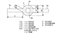
以下においては、本発明の発光ランプを、水銀ランプを例に上げて説明する。図1は本発明の実施形態1を説明するための水銀ランプの外観図である。図1による水銀ランプは、一対の放電用電極1a,1bが内蔵された略球状(ほぼ球体の形状を含む)のバルブ部2を有する。そして、そのバルブ部2の両側にバルブ部2と一体になっていて、そのバルブ部2から連続して左右側に延設された等しい径及び長さの封止部3a,3bを備える。バルブ部2と封止部3a,3bとは石英ガラスなどの透明材料により一体的に成形されている。封止部3a,3bの内部には、電極1a,1bにつながる導体4a,4bが配設されており、封止部3a,3bの端部からそれら導体が外部に伸びている。なお、図1ではバルブ部2の内部に封入されている水銀や希ガスなどは記載を省略している。
In the following, the light emitting lamp of the present invention will be described by taking a mercury lamp as an example. FIG. 1 is an external view of a mercury lamp for explaining
図1のような水銀ランプにおいて、そのエネルギー分布は表1のようになることが実測により分かっている。このうち、本発明では、対流と伝導による熱損失を考慮する。それは、これらの熱損失がバルブ部2の発熱に主として寄与しているからである。表1によれば、対流と伝導による熱損失エネルギーは全体の6.6%である。これを、所定の消費ランプ電力(定格電力ともいう、以下ランプ電力という)に応じてそれぞれ表した熱損失が表2に示されている。表2によれば、ランプ電力100Wのとき対流と伝導による熱損失は6.6W、ランプ電力130Wのとき対流と伝導による熱損失は8.6W、ランプ電力150Wのとき対流と伝導による熱損失は9.9Wなどとなっている。
In the mercury lamp as shown in FIG. 1, it is known from actual measurement that the energy distribution is as shown in Table 1. Of these, in the present invention, heat loss due to convection and conduction is considered. This is because these heat losses mainly contribute to the heat generation of the

発光ランプにおいては、バルブ部2の各サイズ(バルブ部の内径ID、バルブ部の外径OD、封止部の径d、及び封止部の長さl)と、上記対流と伝導による熱損失量が分かると、発光時におけるバルブ部2の表面温度及び内面温度理論値を算出することができる。したがって、バルブ部の内径ID、バルブ部の外径OD、封止部の径d、及び封止部の長さlの4つのサイズの値のうちの3つの値と、ランプ電力に依存するバルブ部2の対流・伝導による熱損失(又は熱損失量)Hとを予め決定し、それらの決定された値を基に、バルブ部2の内面温度理論値が予め定めた目標値となるように、バルブ部2の各サイズのうちの未定としていたサイズの値を決定することができる。例えば、上記バルブ部2の内径ID、封止部3a、3bの径d、封止部3a、3bの長さl、及びバルブ部2の内面温度理論値の目標値を予め設定しておけば、それらの値を基に、バルブ部2の外径ODを決定することができる。
In the light-emitting lamp, each size of the bulb part 2 (bulb part inner diameter ID, bulb part outer diameter OD, sealing part diameter d, and sealing part length l), and heat loss due to the convection and conduction described above. If the amount is known, the theoretical values of the surface temperature and the inner surface temperature of the
以下において、バルブ部2の外径ODを最終的に求める手順の一例を、図2、図3を参照しながら詳細に説明する。なお、以下で用いる符号は、それぞれ次のとおりである。
OS:バルブ部の外側表面積
C:球体の自然対流による熱伝達の形状係数=0.63
OD:バルブ部の外径
d:封止部径(直径)
s:封止部断面積
l:封止部長さ
ID:バルブ部の内径
TH:バルブ部の肉厚
MS:バルブ部の厚さ方向中央位置におけるバルブ面積
R1:バルブ部からの自然対流抵抗
R2:封止部への伝導抵抗
Hereinafter, an example of a procedure for finally obtaining the outer diameter OD of the
OS: Outside surface area of the valve
C: Shape factor of heat transfer by natural convection of a sphere = 0.63
OD: Outer diameter of valve
d: Sealing part diameter (diameter)
s: Sealing section cross section
l: Sealing part length
ID: Inside diameter of valve
TH: Valve wall thickness
MS: Valve area at the center in the thickness direction of the valve
R1: Natural convection resistance from the valve
R2: Conduction resistance to the sealing part
図2のバルブ部2の外側表面積OS(封止部3a,3bとの接触部を除いた面積)は、
OS=4π(OD/2)2−2s
=4π(OD/2)2−2π(d/2)2 …(1)
The outer surface area OS (the area excluding the contact portions with the sealing
OS = 4π (OD / 2) 2 -2s
= 4π (OD / 2) 2 -2π (d / 2) 2 (1)
式(1)で定まる外側表面積を有するバルブ部が、熱損失Hによって発熱したときのバルブ部2の表面温度Tは、封止部3a,3bでの放熱が無いものとした場合、
T=(H/(OS×2.51×C))0.8×(OD/2)0.2 …(2)
ただし、「C」は球体の自然対流熱伝導係数であって、C=0.63である。
したがって、バルブ部2での自然対流への熱抵抗R1は、
R1=T/H …(3)
となる。
The surface temperature T of the
T = (H / (OS × 2.51 × C)) 0.8 × (OD / 2) 0.2 (2)
However, “C” is the natural convection heat conduction coefficient of the sphere, and C = 0.63.
Therefore, the thermal resistance R1 to natural convection in the
R1 = T / H (3)
It becomes.
一方、バルブ部2から封止部3a,3bへ伝導によって放熱される際の熱抵抗R2は、
R2=l/(ρ・s)
=l/(ρ・π(d/2)2) …(4)
なお、バルブ部2における上記熱抵抗R1,R2は、図3のように模式化できる。
On the other hand, the thermal resistance R2 when radiated by conduction from the
R2 = 1 / (ρ · s)
= L / (ρ · π (d / 2) 2 ) (4)
The thermal resistances R1 and R2 in the
バルブ部2での自然対流への熱抵抗R1と、バルブ部2から封止部3a,3bへ伝導によって放熱される際の熱抵抗R2とから、それらの合成抵抗R3は、
1/R3=(1/R1)+(1/R2)+(1/R2)
したがって、
R3=(R1・R2)/(2R1+R2) …(5)
となる。
From the thermal resistance R1 to natural convection in the
1 / R3 = (1 / R1) + (1 / R2) + (1 / R2)
Therefore,
R3 = (R1 / R2) / (2R1 + R2) (5)
It becomes.
バルブ部2に合成抵抗R3が作用した場合のバルブ部2の表面温度TTは、
TT=H・R3 …(6)
また、上記表面温度TTを基に、バルブ部2の肉厚THを考慮して得られるバルブ部2の内面温度理論値ITT(これは発光しているバルブ部の部位によって相違する内面温度の平均値と見なすことができ、本発明では内面温度理論値ITTを内面温度の平均値とも称す)は、
ITT=TT+(H・TH)/(ρ・MS) …(7)
ただし、MSはバルブ部2の厚さ方向の中央位置におけるバルブ面積であって、
TH=(OD−ID)/2 …(8)
MS=4π((ID/2)+(TH/2))2 …(9)
である。
The surface temperature TT of the
TT = H ・ R3 (6)
Further, based on the surface temperature TT, the inner surface temperature theoretical value ITT of the
ITT = TT + (H • TH) / (ρ • MS) (7)
However, MS is the valve area at the central position in the thickness direction of the
TH = (OD-ID) / 2 (8)
MS = 4π ((ID / 2) + (TH / 2)) 2 (9)
It is.
従って、バルブ部2の内面温度理論値ITT、バルブ部の内径ID、封止部の径d、及び封止部の長さlの値を予め決定しておけば、式(7)、(8)、(9)から、バルブ部の外径ODが最終的に求まる。なおその場合に、バルブ部2の内面温度理論値ITTを所定の目標範囲として設定し、それの範囲に対応したバルブ部2の外径ODを決定するようにしてもよい。例えば、プロジェクタなどに使用される高輝度の水銀ランプの場合には、バルブ部2の内面温度理論値ITTが900℃以上で1000℃以下となるように管理するのが好ましく、内面温度理論値ITTがその範囲にとなるように、コンピュータ解析などを利用してバルブ部2の外径ODを決定する。
また、図11に示すような、外形が略球状で、内面が両電極方向を光軸とした場合にこの光軸が長軸となる回転楕円面の形状を有するバルブ部2に対しても、本発明のODを決定する式が成り立つ。ただし、このときのIDは、楕円の短軸の径となる。
Accordingly, if values of the inner surface temperature theoretical value ITT of the
Further, as shown in FIG. 11, when the outer shape is substantially spherical, and the inner surface has both electrode directions as the optical axis, the
バルブ部2の内面温度理論値ITTを900℃〜1000℃にする理由は次のとおりである。発光ランプは通常石英からなっており、その耐熱温度(軟化点1500℃)以上の温度で使用することはできない。また、石英は軟化しなくても、1100℃近くになると、表面が再結晶化をおこして白濁し、透明性を失って明るさの損失になる。一方、800℃近い温度では、ハロゲンサイクルがうまく回らなくなって、発光ランプ表面に電極のタングステンが付着して黒くなり、明るさを低下させることもある。さらに、バルブ部2の内部温度は、内部の対流などによって上下で200℃程度の温度差が生じることがあり、実際には、バルブ部2の内面上側では1050℃程度までの温度となること、そしてバルブ部2の内面下側では850℃程度までの温度となることが想定されている。これらを考慮して、バルブ部2の内面上部と内面下部の温度を平均した温度は、概ね900℃〜1000℃の範囲に設定する。
The reason why the inner surface temperature theoretical value ITT of the
また、発光ランプには、そのバルブ部2から射出された光を再度バルブ部2へ戻すように、バルブ部2の表面又は表面近くに反射手段を設けたものがある。これには、例えば、バルブ部2の表面のほぼ半分に反射膜を被膜したものや、バルブ部2の表面のほぼ半分を隙間を有して配置した反射鏡(以下第二反射鏡という)で覆うようにしたものなどがある。このような構造の発光ランプは、バルブ部2での熱損失が反射手段の存在によって増大する。この場合のバルブ部2の各サイズも、前述した方法(式)を用いて同様に算出決定することができる。ただし、この場合の熱損失は、例えば以下のようにして求める。
Some light emitting lamps are provided with reflecting means on or near the surface of the
表3は、バルブ部2の近傍に第二反射鏡を配した発光ランプにおけるエネルギー分布である。これらのランプの場合、可視光の損失が実測により測定でき、測定したその可視光損失分を熱損失(輻射、対流、伝導を含む)とみなしてよい。そして、その熱損失を、表1の輻射と、対流・伝導とによる損失比に応じて分配して得たのが、表3のエネルギー分布である。さらに、この表3を基にランプ電力に対応させて対流・伝導による熱損失を算出したのが表4である。この表4は表2に対応するものである。
Table 3 shows the energy distribution in the light-emitting lamp in which the second reflecting mirror is disposed in the vicinity of the
ところで、実際の発光ランプでは、バルブ部2の外径ODが小さくなると封止部3a,3bの断面積sがバルブ部2の表面積に対して大きな割合となり、それによってバルブ部2からの出射光が封止部3a,3bによって遮られる割合が増大する。そこで、図4に示すように、バルブ部2の電極1a,1b間中心からバルブ部2と封止部3a,3bとの境界の端部5までを結ぶ仮想線と、電極1a,1b間を結ぶ基準線とのなす角度Φを40度以内とするのがよい。なお、バルブ部2と封止部3a,3bとは同一材料により連続しているが、便宜的に仮想的な境界(破線表示)を想定している。また、この40度という値は次の理由に基づく。ある基準長さの均等な明るさの光源による配光特性を、0〜180度まで累積してその比を算出し、縦軸に明るさの比を、横軸に角度を取って図示すると、図5のようになる。この図5から、角度0〜40度および角度140〜180度の範囲の明るさ比は、合計でも0.2以内に収まることがわかる。そこで、この角度に対応する部分、すなわち電極間中心を結ぶ線を基準線としてその±40度の範囲に、封止部3a,3bが来るようにすれば、電極1a,1bで発生した発光光の80%以上が利用可能となるからである。
By the way, in an actual light-emitting lamp, when the outer diameter OD of the
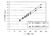
次に、上記の式(7)、(8)、(9)を利用して、バルブ部2の外径を求めた具体例を示す。まず、予め定めたサイズは、バルブ部の内径ID:4.9mm、封止部の径d:5.5mm、封止部長さl:20mmである。また、発光ランプは、第二反射鏡無しの場合と第二反射鏡ありの場合とに対して、それぞれ表2、表4のランプ電力を設定し、それらの表中にある対流・伝導による熱損失値を用いた。そして、第二反射鏡無しの場合と第二反射鏡有りの場合とにおいて、バルブ部の内面温度理論値ITTを900℃以上1000℃以下の範囲内に管理する場合における、バルブ部の外径ODをそれぞれ算出した。その結果は、図6、図7にドット表示されており、それらのドットがラインで結ばれている。従って、この条件において、バルブ部の外径ODは、第二反射鏡無しの場合にはランプ電力に対応する図6の2本のラインの間(ライン上を含む)に、第二反射鏡有りの場合にはランプ電力に対応する図7の2本のラインの間(ライン上を含む)に決定されればよい。
Next, the specific example which calculated | required the outer diameter of the valve |
なお、実施形態1では、発光ランプのバルブ部の外形が略球状の場合を例に説明したが、本発明はバルブ部の形状が他の形状の場合にも適用できる。例えば、図12に示すような、バルブ部の外形及び内形が回転楕円面形状であるものにも適用できる。ただし、この場合におけるバルブ部の外径OD決定のための算出に際しては、先に説明した球状に特有の計算式を、楕円形状の特性に合わせて調整、変更して行う必要がある。 In the first embodiment, the case where the bulb portion of the light emitting lamp has a substantially spherical shape has been described as an example. However, the present invention can also be applied to cases where the bulb portion has other shapes. For example, the present invention can be applied to a valve portion whose outer shape and inner shape are spheroid shapes as shown in FIG. However, in the calculation for determining the outer diameter OD of the valve portion in this case, it is necessary to adjust and change the above-described calculation formula peculiar to the spherical shape according to the characteristics of the elliptical shape.
実施形態2
次に、上記の方法を用いてサイズが決定された発光ランプを備えた照明装置について説明する。図8は本発明の実施形態2の第1の照明装置100に係る構成図である。照明装置100は、発光ランプ10と、発光ランプ10のバルブ部2から後方に射出された光を前方に向けて反射する第一反射鏡20とを備えてなる。第一反射鏡20の形状は例えば楕円状とすることができる。発光ランプ10は、第一反射鏡20の底部の貫通穴21にその封止部2の一端3aが挿入され、そこでセメントなどの無機系接着剤22により第一反射鏡20と一体に固定されている。なお、各封止部3a,3bには、電極1a,1bと接続されたモリブデンからなる金属箔14a,14bが密封され、その金属箔14a,14bには外部につなげられるリード線15a,15bがそれぞれ設けられている。
Next, an illuminating device including a light emitting lamp whose size is determined using the above method will be described. FIG. 8 is a configuration diagram according to the
また、図9は本発明の実施形態2の第2の照明装置100Aに係る構成図である。ここで、図8と同じ符号のものは図8に示したものと同一物又は相当物を示している。この照明装置100Aは、発光ランプ10Aがそのバルブ部2から前方に射出された光を再度バルブ部2へ戻す第二反射鏡6を備えている。第二反射鏡6は、その反射面がバルブ部2の前側ほぼ半分を包囲し、かつ、電極1a,1b中心から射出されてこの第二反射鏡6に入る入射光と該第二反射鏡6の反射面における法線とが一致するように配置されている。第二反射鏡6はセメント31などにより封止部の一方3bに固定されている。また、第一反射鏡20が楕円形状の場合、電極1a,1b間中心を第一反射鏡20の第1焦点F1の位置とほぼ同位置に位置決めされる。なお、第二反射鏡6の反射面がバルブ部2の前側ほぼ半分を包囲していることから、第一反射鏡20の反射面はバルブ部2の後側ほぼ半分をカバーする大きさでよい。これにより、第一反射鏡20は図8の場合に比べてかなり小さくなっている。また、これによって発光ランプ10Aの多くの部分が、第一反射鏡20の反射面開口端より外側に突出している。
FIG. 9 is a configuration diagram according to the
バルブ部2と第二反射鏡6との間には、0.2mm以上の隙間を設けて、第二反射鏡6で覆われている側のバルブ部2の放熱を促進させるようにしておくのがよい。なお、第二反射鏡6の背面は、その反射面側から入射した光(赤外線、紫外線、反射面側から漏れてきた可視光など)を透過させるように、あるいは、その反射面側から入射した光を拡散反射させるような反射膜や形状を備えるように成形して、第二反射鏡6ができるだけ光を吸収しないようにしておく。
A gap of 0.2 mm or more is provided between the
以上の構成による照明装置100Aは次のように作用する。すなわち、バルブ部2後側からの出射光は、第一反射鏡20により反射されて照明装置100Aの前方に向かう。また、バルブ部2前側から出射した光は、第二反射鏡6により反射されて再度バルブ部2に戻り、そこから第一反射鏡20に入射する。そして、その光もまた第一反射鏡20により反射されて照明装置100Aの前方に向かう。これにより、バルブ部2から射出した光のほとんどが利用可能となる。
実施形態2の照明装置100,100Aによれば、そこに用いられている発光ランプ10、10Aの温度が適切な値に維持されるため、ランプの白濁や黒色化が回避され、照明光の品質低下防止が図れる。
The
According to the illuminating
実施形態3
図10は本発明の発光ランプ、ここでは発光ランプ10Aを備えたプロジェクタの構成図である。この光学系は、発光ランプ10A、第一反射鏡20及び第二反射鏡6からなる照明装置100Aと、照明装置100Aからの出射光を所定の光に調整する手段とを備えた照明光学系300と、ダイクロイックミラー382,386、反射ミラー384等を有する色光分離光学系380と、入射側レンズ392、リレーレンズ396、反射ミラー394,398を有するリレー光学系390と、各色光に対応するフィールドレンズ400,402,404及び光変調装置としての液晶パネル410R,410G,410Bと、色光合成光学系であるクロスダイクロイックプリズム420と、投写レンズ600とを備えている。
Embodiment 3
FIG. 10 is a block diagram of a projector provided with a light emitting lamp of the present invention, here a
次に、上記構成のプロジェクタの作用を説明する。まず、発光ランプ10Aのバルブ部2の中心より後側からの出射光は、第一反射鏡20により反射されて照明装置100Aの前方に向かう。また、バルブ部2の中心より前側からの出射光は、第二反射鏡6により反射されて第一反射鏡20に戻った後、第一反射鏡20により反射されて照明装置100Aの前方に向かう。
Next, the operation of the projector having the above configuration will be described. First, the emitted light from the rear side of the center of the
照明装置100Aを出た光は凹レンズ200に入り、そこで光の進行方向が照明光学系300の光軸1とほぼ平行に調整された後、インテグレータレンズを構成する第1レンズアレイ320の各小レンズ321に入射する。第1レンズアレイ320は、入射光を小レンズ321の数に応じた複数の部分光束に分割する。第1レンズアレイ320を出た各部分光束は、その各小レンズ321にそれぞれ対応した小レンズ341を有してなるインテグレータレンズを構成する第2レンズアレイ340に入射する。そして、第2レンズアレイ340からの出射光は、偏光変換素子アレイ360の対応する偏光分離膜(図示省略)の近傍に集光される。その際、遮光板(図示省略)により、偏光変換素子アレイ360への入射光のうち、偏光分離膜に対応する部分にのみ光が入射するように調整される。
The light exiting the
偏光変換素子アレイ360では、そこに入射した光束が同じ種類の直線偏光に変換される。そして、偏光変換素子アレイ360で偏光方向が揃えられた複数の部分光束は重畳レンズ370に入り、そこで液晶パネル410R,410G,410Bを照射する各部分光束が、対応するパネル面上で重さなり合うように調整される。
In the polarization
色光分離光学系380は、第1及び第2ダイクロイックミラー382,386を備え、照明光学系から射出される光を、赤、緑、青の3色の色光に分離する機能を有している。第1ダイクロイックミラー382は、重畳レンズ370から射出される光のうち赤色光成分を透過させるとともに、青色光成分と緑色光成分とを反射する。第1ダイクロイックミラー382を透過した赤色光は、反射ミラー384で反射され、フィールドレンズ400を通って赤色光用の液晶パネル410Rに達する。このフィールドレンズ400は、重畳レンズ370から射出された各部分光束をその中心軸(主光線)に対して平行な光束に変換する。他の液晶パネル410G,410Bの前に設けられたフィールドレンズ402,404も同様に作用する。
The color light separation
さらに、第1ダイクロイックミラー382で反射された青色光と緑色光のうち、緑色光は第2ダイクロイックミラー386によって反射され、フィールドレンズ402を通って緑色光用の液晶パネル410Gに達する。一方、青色光は、第2ダイクロイックミラー386を透過し、リレー光学系390、すなわち、入射側レンズ392、反射ミラー394、リレーレンズ396、及び反射ミラー398を通り、さらにフィールドレンズ404を通って青色光用の液晶パネル410Bに達する。なお、青色光にリレー光学系390が用いられているのは、青色光の光路長が他の色光の光路長よりも長いため、光の発散等による光の利用効率の低下を防止するためである。すなわち、入射側レンズ392に入射した部分光束をそのまま、フィールドレンズ404に伝えるためである。なお、リレー光学系390は、3つの色光のうちの青色光を通す構成としたが、赤色光等の他の色光を通す構成としてもよい。
Further, of the blue light and green light reflected by the first
3つの液晶パネル410R,410G,410Bは、入射した各色光を、与えられた映像情報に従って変調し、各色光の画像を形成する。なお、3つの液晶パネル410R,410G,410Bの光入射面側、光出射面側には、通常、偏光板が設けられている。
The three
上記の各液晶パネル410R,410G,410Bから射出された3色の変調光は、これらの変調光を合成してカラー画像を形成する色光合成光学系としての機能を有するクロスダイクロイックプリズム420に入る。クロスダイクロイックプリズム420には、赤色光を反射する誘電体多層膜と、青色光を反射する誘電体多層膜とが、4つの直角プリズムの界面に略X字状に形成されている。これらの誘電体多層膜によって赤、緑、青の3色の変調光が合成されて、カラー画像を投写するための合成光が形成される。そして、クロスダイクロイックプリズム420で合成された合成光は、最後に投写レンズ600に入り、そこからスクリーン上にカラー画像として投写表示される。
The three colors of modulated light emitted from each of the
上記プロジェクタによれば、そこに用いられている発光ランプ10Aの温度が適切な値に維持されるため、発光ランプの白濁や黒色化が回避されて、プロジェクタの表示画像の質の劣化を抑制できる。
According to the projector, since the temperature of the
本発明の発光ランプは、各種照明装置、光学装置の光源として利用できる。 The light emitting lamp of the present invention can be used as a light source for various illumination devices and optical devices.
1a,1b…電極、2…バルブ部、3a,3b…封止部、4a,4b…導体、5…バルブ部と封止部との境界の端部、6…第二反射鏡、10,10A…発光ランプ。
DESCRIPTION OF
Claims (10)
前記バルブ部の内径、前記バルブ部の外径、前記封止部の径、及び前記封止部の長さの4つのサイズの値のうちの3つの値と、消費電力に依存する前記バルブ部の対流・伝導による熱損失量値とを予め決定し、それらの決定された値を基に、前記バルブ部の内面温度の平均値が予め定めた目標値となるように、前記バルブ部の各サイズのうちの残りの1つのサイズの値を決定する、ことを特徴とする発光ランプのサイズ決定方法。 A method for determining a size of a light-emitting lamp, comprising: a bulb portion including a pair of electrodes; and a sealing portion disposed on both sides of the bulb portion and integrally provided with the bulb portion and provided with a conductor connected to the electrode. ,
The valve portion that depends on three values of four values of the inner diameter of the valve portion, the outer diameter of the valve portion, the diameter of the sealing portion, and the length of the sealing portion, and power consumption Heat loss amount values due to convection / conduction of each of the valve portions, and based on the determined values, the average value of the inner surface temperature of the valve portion becomes a predetermined target value. A method for determining the size of a light-emitting lamp, characterized in that the value of the remaining one of the sizes is determined.
前記熱損失量、前記バルブ部の内径、前記封止部の径、及び前記封止部の長さを基に、前記バルブ部の内面温度の平均値が目標範囲内に収まるように、前記バルブ部の外径を決定する、ことを特徴とする請求項1記載の発光ランプのサイズ決定方法。 The amount of heat loss due to convection and conduction of the valve part, the inner diameter of the valve part, the diameter of the sealing part, and the length of the sealing part are determined in advance.
Based on the heat loss amount, the inner diameter of the valve portion, the diameter of the sealing portion, and the length of the sealing portion, the valve temperature is adjusted so that the average value of the inner surface temperature of the valve portion is within a target range. 2. The method of determining a size of a light-emitting lamp according to claim 1, wherein an outer diameter of the portion is determined.
ITT=TT+(H・TH)/(ρ・MS)
ここで、TTは前記バルブ部の表面温度、Hは前記バルブ部の対流・伝導による熱損失量、THは前記バルブ部の肉厚、ρは前記バルブ及び前記封止部を構成する材料の熱伝導率、MSは前記バルブ部の厚さ方向中央位置におけるバルブ面積である、ことを特徴とする請求項1又は2記載の方法。 When the average value of the inner surface temperature is ITT,
ITT = TT + (H ・ TH) / (ρ ・ MS)
Here, TT is the surface temperature of the valve part, H is the amount of heat loss due to convection and conduction of the valve part, TH is the thickness of the valve part, and ρ is the heat of the material constituting the valve and the sealing part. The method according to claim 1, wherein the conductivity, MS, is a valve area at a central position in the thickness direction of the valve portion.
TT=H・R3、
R3=(R1・R2)/(2R1+R2)、
R1=T/H、
R2=l/(ρ・π・(d/2)2)、
であって、Tは前記バルブ部の前記封止部からの放熱がないとした場合の前記バルブ部の表面温度、R3は前記バルブ部から自然対流への熱抵抗R1と前記バルブ部から前記封止部への伝導による熱抵抗R2との合成抵抗であり、lは前記封止部の長さ、dは前記封止部の直径である、ことを特徴とする請求項3記載の方法。 The surface temperature TT of the valve part is
TT = H ・ R3,
R3 = (R1 ・ R2) / (2R1 + R2),
R1 = T / H,
R2 = l / (ρ · π · (d / 2) 2 ),
Where T is the surface temperature of the valve part when there is no heat dissipation from the sealing part of the valve part, and R3 is the thermal resistance R1 from the valve part to natural convection and the sealing from the valve part. 4. A method according to claim 3, characterized in that it is a combined resistance with the thermal resistance R2 due to conduction to the stop, wherein l is the length of the sealing part and d is the diameter of the sealing part.
Priority Applications (4)
| Application Number | Priority Date | Filing Date | Title |
|---|---|---|---|
| JP2003302476A JP2005070589A (en) | 2003-08-27 | 2003-08-27 | Method of determining size of light emitting lamp, light emitting lamp, and lighting device and projector provided with light emitting lamp |
| US10/921,105 US20050082986A1 (en) | 2003-08-27 | 2004-08-19 | Light-emitting lamp, and illumination apparatus and projector provided with the light-emitting lamp |
| PCT/JP2004/012430 WO2005022584A1 (en) | 2003-08-27 | 2004-08-23 | Light emitting lamp, lighting apparatus having the light emitting lamp, and projector |
| CNA2004800215328A CN1830060A (en) | 2003-08-27 | 2004-08-23 | Light emitting lamp, lighting apparatus having the light emitting lamp, and projector |
Applications Claiming Priority (1)
| Application Number | Priority Date | Filing Date | Title |
|---|---|---|---|
| JP2003302476A JP2005070589A (en) | 2003-08-27 | 2003-08-27 | Method of determining size of light emitting lamp, light emitting lamp, and lighting device and projector provided with light emitting lamp |
Publications (2)
| Publication Number | Publication Date |
|---|---|
| JP2005070589A true JP2005070589A (en) | 2005-03-17 |
| JP2005070589A5 JP2005070589A5 (en) | 2005-08-11 |
Family
ID=34269178
Family Applications (1)
| Application Number | Title | Priority Date | Filing Date |
|---|---|---|---|
| JP2003302476A Withdrawn JP2005070589A (en) | 2003-08-27 | 2003-08-27 | Method of determining size of light emitting lamp, light emitting lamp, and lighting device and projector provided with light emitting lamp |
Country Status (4)
| Country | Link |
|---|---|
| US (1) | US20050082986A1 (en) |
| JP (1) | JP2005070589A (en) |
| CN (1) | CN1830060A (en) |
| WO (1) | WO2005022584A1 (en) |
Cited By (1)
| Publication number | Priority date | Publication date | Assignee | Title |
|---|---|---|---|---|
| WO2012014608A1 (en) * | 2010-07-26 | 2012-02-02 | 岩崎電気株式会社 | High-intensity discharge lamp |
Families Citing this family (6)
| Publication number | Priority date | Publication date | Assignee | Title |
|---|---|---|---|---|
| JP2005283706A (en) * | 2004-03-29 | 2005-10-13 | Seiko Epson Corp | Lamp device and projector equipped therewith |
| JP4582036B2 (en) * | 2006-03-28 | 2010-11-17 | セイコーエプソン株式会社 | Discharge lamp lighting device and projector |
| US8203280B2 (en) * | 2007-12-14 | 2012-06-19 | Seiko Epson Corporation | Light source device, projector, and driving method of discharge lamp |
| JP4572940B2 (en) | 2008-02-19 | 2010-11-04 | セイコーエプソン株式会社 | Discharge lamp driving method, driving device, and projector |
| JP4525774B2 (en) * | 2008-02-27 | 2010-08-18 | セイコーエプソン株式会社 | Discharge lamp driving method, driving device, and projector |
| JP4525775B2 (en) | 2008-02-29 | 2010-08-18 | セイコーエプソン株式会社 | Discharge lamp driving method, driving device, and projector |
Family Cites Families (8)
| Publication number | Priority date | Publication date | Assignee | Title |
|---|---|---|---|---|
| JPH05174787A (en) * | 1991-12-26 | 1993-07-13 | Matsushita Electric Ind Co Ltd | Metal halide lamp |
| US5497049A (en) * | 1992-06-23 | 1996-03-05 | U.S. Philips Corporation | High pressure mercury discharge lamp |
| JP3184404B2 (en) * | 1994-07-13 | 2001-07-09 | 松下電子工業株式会社 | Metal halide lamp with reflector |
| JP3847927B2 (en) * | 1997-11-18 | 2006-11-22 | キヤノン株式会社 | Arc tube and light source device using the same |
| JP2857137B1 (en) * | 1997-12-25 | 1999-02-10 | ウシオ電機株式会社 | Short arc mercury lamp |
| US6559600B1 (en) * | 1998-11-17 | 2003-05-06 | Matsushita Electric Industrial Co., Ltd. | Discharge lamp, light source and projecting display unit |
| US6307321B1 (en) * | 1999-07-14 | 2001-10-23 | Toshiba Lighting & Technology Corporation | High-pressure discharge lamp and lighting apparatus |
| JP4075303B2 (en) * | 2000-11-01 | 2008-04-16 | セイコーエプソン株式会社 | projector |
-
2003
- 2003-08-27 JP JP2003302476A patent/JP2005070589A/en not_active Withdrawn
-
2004
- 2004-08-19 US US10/921,105 patent/US20050082986A1/en not_active Abandoned
- 2004-08-23 WO PCT/JP2004/012430 patent/WO2005022584A1/en active Application Filing
- 2004-08-23 CN CNA2004800215328A patent/CN1830060A/en active Pending
Cited By (2)
| Publication number | Priority date | Publication date | Assignee | Title |
|---|---|---|---|---|
| WO2012014608A1 (en) * | 2010-07-26 | 2012-02-02 | 岩崎電気株式会社 | High-intensity discharge lamp |
| US8575837B2 (en) | 2010-07-26 | 2013-11-05 | Iwasaki Electric Co., Ltd. | High pressure discharge lamp |
Also Published As
| Publication number | Publication date |
|---|---|
| CN1830060A (en) | 2006-09-06 |
| US20050082986A1 (en) | 2005-04-21 |
| WO2005022584A1 (en) | 2005-03-10 |
Similar Documents
| Publication | Publication Date | Title |
|---|---|---|
| US7695160B2 (en) | Projector light source and projection type image display device using the same | |
| JP4096598B2 (en) | Light source for projection apparatus and projection-type image display apparatus using the same | |
| JP4715916B2 (en) | LIGHTING DEVICE AND PROJECTOR HAVING THE SAME | |
| US5479065A (en) | Metal halide discharge lamp suitable for an optical light source having a bromine to halogen ratio of 60-90%, a wall load substantially greater than 40 W/cm2, and a D.C. potential between the anode and cathode | |
| TWI285247B (en) | Light source device and projector | |
| JP4235829B2 (en) | LIGHTING DEVICE AND PROJECTOR HAVING THE LIGHTING DEVICE | |
| US7252410B2 (en) | Projector | |
| JPWO2005088189A1 (en) | LIGHTING DEVICE AND PROJECTOR HAVING THE SAME | |
| JP2005070589A (en) | Method of determining size of light emitting lamp, light emitting lamp, and lighting device and projector provided with light emitting lamp | |
| JP4302082B2 (en) | How to design a discharge lamp | |
| JP2010060855A (en) | Optical apparatus | |
| JPH1196803A (en) | Light source device | |
| US8449343B2 (en) | Discharge lamp having a heat resistant film and method for producing same | |
| JP2007335196A (en) | Light source device and projector | |
| JP2005005183A (en) | High-pressure mercury lamp, light source device, and projector | |
| JP2005077585A (en) | Lamp device and projector equipped therewith | |
| JP2008102168A (en) | Projector | |
| JP2002231184A (en) | Light source device and projector using the same | |
| JP2005228711A (en) | Optical apparatus | |
| JP2005062735A (en) | Method for designing reflector, reflector, light emission lamp equipped with same, luminaire, and projector | |
| JP2006120358A (en) | Light source device and projector | |
| JP2005038685A (en) | Lighting device, projector and arc tube | |
| JP2007323929A (en) | Light source device | |
| JPH05333433A (en) | Projection light source device and liquid crystal projector device using the same | |
| JPH04367835A (en) | Lighting optical device and projection type display device using the same |
Legal Events
| Date | Code | Title | Description |
|---|---|---|---|
| A521 | Written amendment |
Free format text: JAPANESE INTERMEDIATE CODE: A523 Effective date: 20050318 |
|
| A621 | Written request for application examination |
Free format text: JAPANESE INTERMEDIATE CODE: A621 Effective date: 20050318 |
|
| A131 | Notification of reasons for refusal |
Free format text: JAPANESE INTERMEDIATE CODE: A131 Effective date: 20080129 |
|
| A761 | Written withdrawal of application |
Free format text: JAPANESE INTERMEDIATE CODE: A761 Effective date: 20080310 |