JP2005062995A - Coin depositing/dispensing device - Google Patents

Coin depositing/dispensing device Download PDF

Info

Publication number
JP2005062995A
JP2005062995A JP2003289654A JP2003289654A JP2005062995A JP 2005062995 A JP2005062995 A JP 2005062995A JP 2003289654 A JP2003289654 A JP 2003289654A JP 2003289654 A JP2003289654 A JP 2003289654A JP 2005062995 A JP2005062995 A JP 2005062995A
Authority
JP
Japan
Prior art keywords
coin
payout
coins
belt
housing
Prior art date
Legal status (The legal status is an assumption and is not a legal conclusion. Google has not performed a legal analysis and makes no representation as to the accuracy of the status listed.)
Granted
Application number
JP2003289654A
Other languages
Japanese (ja)
Other versions
JP3818515B2 (en
Inventor
Toshihiro Kaneko
俊弘 兼子
Current Assignee (The listed assignees may be inaccurate. Google has not performed a legal analysis and makes no representation or warranty as to the accuracy of the list.)
Toshiba TEC Corp
Original Assignee
Toshiba TEC Corp
Priority date (The priority date is an assumption and is not a legal conclusion. Google has not performed a legal analysis and makes no representation as to the accuracy of the date listed.)
Filing date
Publication date
Application filed by Toshiba TEC Corp filed Critical Toshiba TEC Corp
Priority to JP2003289654A priority Critical patent/JP3818515B2/en
Publication of JP2005062995A publication Critical patent/JP2005062995A/en
Application granted granted Critical
Publication of JP3818515B2 publication Critical patent/JP3818515B2/en
Anticipated expiration legal-status Critical
Expired - Fee Related legal-status Critical Current

Links

Images

Abstract

<P>PROBLEM TO BE SOLVED: To provide a coin depositing/dispensing device capable of unconsciously periodically cleaning a dispensing belt mechanically. <P>SOLUTION: This coin depositing/dispensing device is provided with a cleaning member 81, which is brought into contact with an outer circumferential face 35a of the dispensing belt 35 dispensing a coin C stored in a coin storage part 8 to clean the outer circumferential face 35a. The cleaning member 81 can be moved freely between a cleaning position, in which the cleaning member 81 is brought into contact with the dispensing belt 35 for cleaning the outer circumferential face 35a, and a separation position, in which the cleaning member 81 is separated from the dispensing belt 35. When batch collection work of the coins C is carried out and all the coins in at least one denomination among the coins stored in the coin storage part 8 are dispensed, the cleaning member 81 is positioned in the cleaning position. In this way, the dispensing belt 35 is cleaned when the batch collection work of the coins C is periodically carried out. <P>COPYRIGHT: (C)2005,JPO&NCIPI

Description

本発明は、硬貨入出金装置に関する。   The present invention relates to a coin deposit / withdrawal apparatus.

従来、POS(Point Of Sales)端末やECR(Electronic Cash Register)などに接続され、商品の取引の際の硬貨の入金及び払出処理を行なう硬貨入出金装置がある。   2. Description of the Related Art Conventionally, there is a coin deposit / withdrawal apparatus that is connected to a POS (Point Of Sales) terminal, an ECR (Electronic Cash Register), or the like, and performs coin depositing and dispensing processing at the time of merchandise transactions.

硬貨入出金装置では、まず、種々の金種が混合した状態で装置手前側に設けられた硬貨投入口に一括投入された硬貨を硬貨搬送部によって硬貨選別部へ搬送する。そして、硬貨選別部において硬貨を硬貨の金種毎に大きさが定められた選別穴により選別して、金種毎に仕切られた硬貨収納部に落下させ硬貨収納部に収納する。そして、POS端末やECRなどからの釣り銭の払い出し指令により、硬貨収納部内の硬貨を硬貨収納部の底部に設けられた払出ベルトによって搬送し、硬貨払出口に払い出すようにしている。   In the coin depositing / dispensing apparatus, first, coins that are collectively loaded into a coin slot provided on the front side of the apparatus in a state where various denominations are mixed are transported to a coin sorting part by a coin transporting part. Then, in the coin sorting unit, the coins are sorted by a sorting hole having a size determined for each denomination of the coins, dropped into the coin storing unit partitioned for each denomination, and stored in the coin storing unit. Then, in accordance with a change payout command from a POS terminal, ECR, or the like, the coins in the coin storage portion are conveyed by a payout belt provided at the bottom of the coin storage portion and are discharged to the coin payout exit.

ここで、このような払出ベルトと同様の硬貨搬送ベルトを用いて硬貨搬送する装置として、硬貨を識別する硬貨処理装置が特許文献1に開示されている。   Here, as a device for transporting coins using a coin transport belt similar to such a payout belt, Patent Document 1 discloses a coin processing device for identifying coins.

特開平10−261127号公報JP-A-10-261127

このような払出ベルトは、硬貨収納部内のゴミが付着したり、硬貨に付いていたゴミが付着するなどして汚れ、硬貨を正常に搬送できなくなるなどの搬送不良が発生してしまう。そこで、メーカのサービスマンが定期的にユーザの所へ赴いて清掃している。しかしながら、このように、サービスマンが定期的にユーザの所へ赴いて清掃するのはメーカにとって負担であるという問題がある。だからといって、ユーザが清掃を行うのも、ユーザにとって負担となってしまうという問題がある。   Such a payout belt is contaminated with dust in the coin storage unit or with dust attached to the coin, and causes a conveyance failure such that the coin cannot be normally conveyed. Therefore, a manufacturer's service person visits the user regularly for cleaning. However, there is a problem that it is a burden on the manufacturer that the service person regularly visits the user for cleaning. However, there is a problem that it is burdensome for the user to perform cleaning.

ここで、特許文献1では、搬送ベルト上に羽根により強制的に送風することにより、搬送ベルト上のゴミを除去し、これにより、硬貨の特徴を精度よく識別できるようにしている。しかしながら、特許文献1には、搬送不良に対する解決手段は明示されていない。   Here, in Patent Document 1, dust on the conveyor belt is removed by forcibly blowing air on the conveyor belt by means of blades, so that the characteristics of coins can be accurately identified. However, Patent Document 1 does not clearly disclose a solution to the conveyance failure.

本発明の目的は、払出ベルトの清掃を意識させることなく定期的に行うことができる硬貨入出金装置を得ることである。   An object of the present invention is to obtain a coin depositing and dispensing apparatus that can be performed periodically without making the payout belt cleaning conscious.

本発明は、硬貨収納部に金種別に収納されている硬貨を払い出す払出ベルトの外周面に当接して前記払出ベルトの外周面を清掃する清掃位置と前記払出ベルトから離反する離反位置との間で移動自在な清掃部材を備える。一括払出手段が一括払出指令に応じて前記払出ベルトを駆動して硬貨収納部に収納されている硬貨のうちの少なくとも一つの金種の硬貨を全て払い出すのに伴って、第一の位置付け手段により前記清掃部材を前記清掃位置に位置付ける。前記一括払出手段による硬貨の払い出しが行われないときには、第二の位置付け手段により前記清掃部材を前記離反位置に位置付ける。   The present invention provides a cleaning position for cleaning the outer peripheral surface of the payout belt by contacting the outer peripheral surface of the payout belt for paying out coins stored in the coin storage in the coin storage portion, and a separation position for separating from the payout belt. A cleaning member that is movable between the two is provided. When the lump-sum payout means drives the payout belt according to a lump-out payout command and pays out all the coins of at least one denomination among the coins stored in the coin storage portion, the first positioning means To position the cleaning member at the cleaning position. When the coins are not paid out by the collective paying means, the cleaning member is positioned at the separation position by the second positioning means.

本発明によれば、払出ベルトの清掃を意識させることなく定期的に行うことができる硬貨入出金装置を得ることができる。   ADVANTAGE OF THE INVENTION According to this invention, the coin depositing / withdrawing apparatus which can be performed regularly, without making the cleaning of a payout belt conscious can be obtained.

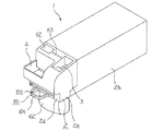
本発明の一実施の形態を図1ないし図9に基づいて説明する。本実施の形態は、商品の売上処理を実行する商品販売データ処理装置であるPOS端末(図示せず)に接続して使用される硬貨入出金装置への適用例である。ここで、図1は本実施の形態の硬貨入出金装置の外観を示す斜視図である。   An embodiment of the present invention will be described with reference to FIGS. The present embodiment is an application example to a coin deposit / withdrawal device used by being connected to a POS terminal (not shown) which is a product sales data processing device for executing product sales processing. Here, FIG. 1 is a perspective view showing the appearance of the coin depositing and dispensing apparatus of the present embodiment.

図1を用いて硬貨入出金装置1を説明する。硬貨入出金装置1は、その概略構造として、硬貨C(図5参照)の入金及び払い出し処理を行なう入出金機構ユニット2aがユニット保持ケース2bに引き出し及び収納自在に保持されて構成される装置本体2と、この装置本体2の入出金機構ユニット2aに着脱自在に取り付けられる回収体であって移動手段である回収袋101とから構成されている。回収袋101が装置本体2に取り付けられた状態の硬貨入出金装置1を図2に示す。   The coin deposit / withdrawal apparatus 1 will be described with reference to FIG. The coin depositing / dispensing apparatus 1 has a schematic structure in which a depositing / dispensing mechanism unit 2a for depositing and dispensing coins C (see FIG. 5) is held in a unit holding case 2b so that it can be pulled out and stored freely. 2 and a collection bag 101 which is a collection body which is detachably attached to the deposit / withdrawal mechanism unit 2a of the apparatus main body 2 and which is a moving means. FIG. 2 shows the coin deposit / withdrawal apparatus 1 in a state where the collection bag 101 is attached to the apparatus main body 2.

回収袋101は、図1に示すように、装置本体2に収納されている全ての硬貨Cを収納可能な上面開口の袋部102と、この袋部102の上端を支持するフレーム枠103とから構成されている。フレーム枠103には取っ手104が設けられている。また、フレーム枠103の取っ手104とは反対側には、回収袋101を装置本体2側に取り付けるための嵌合部105が形成されている。   As shown in FIG. 1, the collection bag 101 includes a bag portion 102 having an upper surface opening that can store all the coins C stored in the apparatus main body 2, and a frame frame 103 that supports the upper end of the bag portion 102. It is configured. A handle 104 is provided on the frame 103. A fitting portion 105 for attaching the collection bag 101 to the apparatus main body 2 side is formed on the opposite side of the frame frame 103 from the handle 104.

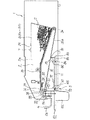
次に入出金機構ユニット2aについて説明する。ここで、図3は設置台上に設置され入出金機構ユニットがユニット保持ケースから引き出された状態の硬貨入出金装置を示す側面図、図4は入出金機構ユニット2aの内部構造を示す平面図、図5は入出金機構ユニット2aの内部構造を示す縦断側面図、図6は回収袋101が取付部に取り付けられた状態の入出金機構ユニット2aの内部構造を示す縦断側面図である。   Next, the deposit / withdrawal mechanism unit 2a will be described. Here, FIG. 3 is a side view showing the coin depositing / dispensing apparatus in a state where the depositing / dispensing mechanism unit is pulled out from the unit holding case, and FIG. 4 is a plan view showing the internal structure of the depositing / dispensing mechanism unit 2a. FIG. 5 is a longitudinal side view showing the internal structure of the deposit / withdrawal mechanism unit 2a, and FIG. 6 is a longitudinal side view showing the internal structure of the deposit / withdrawal mechanism unit 2a with the collection bag 101 attached to the mounting portion.

図3に示すように、入出金機構ユニット2aは、スライドレール機構2cによってユニット保持ケース2bに対して引き出し及び収納自在に保持されており、その引き出し方向は装置手前側である。この入出金機構ユニット2aは、以下に説明する各部がハウジング2dによりユニット化されて構成されている。   As shown in FIG. 3, the deposit / withdrawal mechanism unit 2a is held by the slide rail mechanism 2c so that it can be pulled out and stored with respect to the unit holding case 2b, and the drawing direction is the front side of the apparatus. The deposit / withdrawal mechanism unit 2a is configured by unitizing each part described below with a housing 2d.

図1に示すように、入出金機構ユニット2aのハウジング2dの右側手前には、上面が開口され硬貨Cが一括して投入される硬貨投入口3が設けられ、ハウジング2dの左側手前には、上面が開口され硬貨Cが払い出される硬貨払出口4が設けられ、この硬貨払出口4よりも下のハウジング2dには、回収袋101をハウジング2dに対してスライド自在かつ着脱自在に保持する回収袋取付部5が設けられている。このハウジング2dには、略全体がユニット保持ケース2bに覆われ、硬貨投入口3から投入された硬貨Cを選別収納しPOS端末などからの払出指令に応じて硬貨Cを硬貨投入口3に払い出す硬貨入出金機構A(図4参照)が設けられている。   As shown in FIG. 1, a coin insertion slot 3 is provided on the right side of the housing 2d of the deposit / withdrawal mechanism unit 2a. A coin payout opening 4 through which the upper surface is opened and the coins C are paid out is provided. A housing 2d below the coin payout opening 4 holds the collection bag 101 slidably and detachably with respect to the housing 2d. A mounting portion 5 is provided. The housing 2d is almost entirely covered with the unit holding case 2b, and the coin C inserted from the coin insertion slot 3 is selectively stored, and the coin C is paid to the coin insertion slot 3 in accordance with a dispensing instruction from a POS terminal or the like. A coin deposit / withdrawal mechanism A (see FIG. 4) is provided.

図5に示すように、回収袋取付部5は、装置の前後方向に長く形成された第一の位置付け手段であるスライド部材71がハウジング2dに固定されたスライド部材保持部72によって装置の前後方向にスライド自在に保持されて構成されている。スライド部材71の前端には、図1に示すように、回収袋101を着脱自在に保持する溝形状の回収袋保持部73が形成されている。即ち、溝形状の回収袋保持部73に回収袋101の嵌合部105が嵌合することにより回収袋101がスライド部材71に保持される。このスライド部材71は、図5に示す、回収袋保持部73への回収袋101の着脱を可能とする着脱位置と、図6に示す、取り付けられた回収袋101を硬貨払出口4の下方の回収位置に位置付ける回収位置との間でスライド自在に設けられている。   As shown in FIG. 5, the collection bag mounting portion 5 is configured so that the slide member 71, which is a first positioning means formed long in the front-rear direction of the apparatus, is supported by a slide member holding part 72 fixed to the housing 2 d. It is configured to be slidably held on the surface. At the front end of the slide member 71, as shown in FIG. 1, a groove-shaped collection bag holding portion 73 for holding the collection bag 101 in a detachable manner is formed. That is, the collection bag 101 is held by the slide member 71 by fitting the fitting portion 105 of the collection bag 101 into the groove-shaped collection bag holding portion 73. The slide member 71 has an attachment / detachment position in which the collection bag 101 can be attached to and detached from the collection bag holding unit 73 shown in FIG. 5, and the attached collection bag 101 shown in FIG. It is slidably provided between a collection position and a collection position.

さらに、スライド部材71の前端には、図1に示すように、回収袋保持部73を覆うためのカバー74が取り付けられている。なお、図5及び図6ではカバー74を省略している。カバー74は、回収袋保持部73を覆う位置(図9参照)と回収袋保持部73を露出する位置(図1参照)との間で軸75によりスライド部材71に回動自在に設けられている。そして、スライド部材71を着脱位置に引き出した状態であってスライド部材71に回収袋101が取り付けられていない状態において、回収袋保持部73を覆う位置にカバー74を回動させてからカバー74を装置の奥側に向けて押すことにより、スライド部材71が装置の後方へ向けて移動し、回収位置よりも手前の位置であるカバー閉じ位置にスライド部材71が位置したときに、カバー74の内側に形成された溝部76がハウジング2dに設けられた係り止め部77に嵌ることにより位置保持され、カバー74はハウジング2dの前端部と一体化する。この状態では、スライド部材71は、回収位置に向かっての移動が規制される。   Further, a cover 74 for covering the collection bag holding portion 73 is attached to the front end of the slide member 71 as shown in FIG. 5 and 6, the cover 74 is omitted. The cover 74 is rotatably provided on the slide member 71 by a shaft 75 between a position that covers the collection bag holding portion 73 (see FIG. 9) and a position that exposes the collection bag holding portion 73 (see FIG. 1). Yes. Then, in a state where the slide member 71 is pulled out to the attachment / detachment position and the collection bag 101 is not attached to the slide member 71, the cover 74 is rotated to a position covering the collection bag holding portion 73 and then the cover 74 is moved. By pushing toward the back side of the apparatus, the slide member 71 moves toward the rear of the apparatus, and when the slide member 71 is positioned at the cover closing position, which is a position before the collection position, the inside of the cover 74 The groove portion 76 formed in is fitted and held in a locking portion 77 provided in the housing 2d, and the cover 74 is integrated with the front end portion of the housing 2d. In this state, the movement of the slide member 71 toward the collection position is restricted.

図4に示すように、硬貨入出金機構Aは、硬貨Cを選別して落下させる硬貨選別部7、硬貨選別部7の下方に配置され硬貨選別部7により落下された硬貨Cを金種毎に収納する硬貨収納部8、硬貨投入口3に投入された硬貨Cを硬貨選別部7へ搬送する硬貨搬送部9、硬貨収納部8に収納された硬貨Cを硬貨払出口4に払い出す硬貨払出搬送部10などから構成されている。   As shown in FIG. 4, the coin depositing / dispensing mechanism A sorts coins C by dropping them, and arranges coins C placed below the coin sorting unit 7 and dropped by the coin sorting unit 7 for each denomination. A coin storage unit 8 for storing the coin C, a coin transport unit 9 for transporting the coin C inserted into the coin insertion slot 3 to the coin sorting unit 7, and a coin for dispensing the coin C stored in the coin storage unit 8 to the coin payout exit 4 The payout conveyance unit 10 and the like are included.

硬貨搬送部9は、硬貨投入口3の底から硬貨収納部8よりも高い位置に硬貨Cを搬送する第一の硬貨搬送部11、第一の硬貨搬送部11によって搬送された硬貨Cを硬貨選別部7へ搬送する第二の硬貨搬送部12から構成されている。   The coin transport unit 9 includes a first coin transport unit 11 that transports the coin C from the bottom of the coin insertion slot 3 to a position higher than the coin storage unit 8, and a coin C transported by the first coin transport unit 11. It is comprised from the 2nd coin conveyance part 12 conveyed to the selection part 7. FIG.

第一の硬貨搬送部11には、硬貨投入口3の底を搬送面13によって形成しモータM(図7参照)に連結されて、硬貨投入口3に投入された搬送面13上の硬貨Cを装置の奥へ搬送する入金搬送ベルト14が設けられている。ここで、搬送面13によって搬送路20が形成されている。硬貨投入口3には、入金搬送ベルト14の駆動制御において用いられる光電的に硬貨Cの有無を検出する複数組の投入センサ6が設けられている。   In the first coin transport section 11, the bottom of the coin insertion slot 3 is formed by the transport surface 13 and connected to the motor M (see FIG. 7), and the coin C on the transport surface 13 inserted into the coin insertion slot 3. Is provided to the inside of the apparatus. Here, a conveyance path 20 is formed by the conveyance surface 13. The coin insertion slot 3 is provided with a plurality of sets of insertion sensors 6 for photoelectrically detecting the presence or absence of coins C used in drive control of the deposit conveyance belt 14.

この入金搬送ベルト14上には、硬貨投入口3の一端に位置させて不規則に投入された硬貨Cを一枚ずつ送り出すための投入口ローラ21が設けられている。   On the deposit conveyance belt 14, there is provided a slot roller 21 that is positioned at one end of the coin slot 3 and feeds the coins C that are randomly loaded one by one.

入金搬送ベルト14の終端部分には、搬送方向を略直角に屈曲する硬貨案内部22が設けられ、この入金搬送ベルト14の終端部分に、第二の硬貨搬送部12が連設されている。   A coin guide portion 22 that bends the conveyance direction at a substantially right angle is provided at the end portion of the deposit conveyance belt 14, and the second coin conveyance portion 12 is connected to the termination portion of the deposit conveyance belt 14.

第二の硬貨搬送部12は、硬貨入出金装置1の幅方向に略平行に設けられ、硬貨案内部22によって搬送方向が略直角に屈曲された硬貨Cを硬貨選別部7に搬送する。第二の硬貨搬送部12には、硬貨Cを底板23の水平な搬送面23aに圧接させて硬貨選別部7へ搬送する搬送ベルト24が設けられている。この搬送面23aは、搬送路25を形成している。   The second coin transport unit 12 is provided substantially parallel to the width direction of the coin depositing / dispensing apparatus 1, and transports the coin C whose transport direction is bent at a substantially right angle by the coin guide unit 22 to the coin sorting unit 7. The second coin transport unit 12 is provided with a transport belt 24 that transports the coin C to the coin sorting unit 7 while being pressed against the horizontal transport surface 23 a of the bottom plate 23. The transport surface 23 a forms a transport path 25.

搬送ベルト24は、エンドレスベルトであって、駆動ローラ26と従動ローラ27とに掛け渡されて設けられ、駆動ローラ26に連結されたモータM(図7参照)により駆動される。そして、搬送ベルト24は、硬貨入出金装置1が水平に設置された状態で、図示しない付勢部材により下方に向けて付勢されている。これにより、搬送ベルト24は、搬送面23a上の硬貨Cを押圧し、硬貨Cを搬送面23aに圧接させる。   The conveyor belt 24 is an endless belt, is provided around a driving roller 26 and a driven roller 27, and is driven by a motor M (see FIG. 7) connected to the driving roller 26. And the conveyance belt 24 is urged | biased below by the urging member which is not shown in figure in the state in which the coin depositing / withdrawing apparatus 1 was installed horizontally. Thereby, the conveyance belt 24 presses the coin C on the conveyance surface 23a and presses the coin C against the conveyance surface 23a.

なお、底板23には、基準面28が設けられている。この基準面28は、搬送路25を搬送される硬貨Cの側面を支持して、硬貨選別部7の後述する選別穴29から硬貨Cを正しく落下させる為に必要な硬貨Cの搬送基準を得る為の硬貨案内面54である。このような第二の硬貨搬送部12の搬送ベルト24の下方に、硬貨選別部7が設けられている。   A reference surface 28 is provided on the bottom plate 23. The reference surface 28 supports the side surface of the coin C conveyed through the conveyance path 25, and obtains the conveyance reference of the coin C necessary for correctly dropping the coin C from a sorting hole 29 described later of the coin sorting unit 7. This is a coin guide surface 54 for the purpose. The coin sorting unit 7 is provided below the transport belt 24 of the second coin transport unit 12.

硬貨選別部7を構成する底板23には、搬送ベルト24に沿わせて、即ち、搬送路25に沿わせて順次穴幅寸法が拡大する金種毎の選別穴29が形成されており、この選別穴29により硬貨Cを金種別に選別する。   The bottom plate 23 constituting the coin sorting unit 7 is formed with a sorting hole 29 for each denomination whose hole width dimension is sequentially increased along the transport belt 24, that is, along the transport path 25. The coins C are sorted by denomination by the sorting hole 29.

選別穴29は、図4において右から1円・50円・5円・100円・10円・500円のそれぞれの金種に対応するように6個設けられている。本実施の形態では、硬貨搬送方向で隣り合う選別穴29同士はそれぞれ連続して形成されており、外見上、一つの穴を形成している。硬貨選別部7は、硬貨Cが搬送されて、所定の外径の選別穴29に到達した際に、金種毎に硬貨収納部8に落下させる。   Six sorting holes 29 are provided so as to correspond to the respective denominations of 1 yen, 50 yen, 5 yen, 100 yen, 10 yen, and 500 yen from the right in FIG. In the present embodiment, the selection holes 29 adjacent in the coin conveyance direction are formed continuously, and form one hole in appearance. When the coin C is transported and reaches the sorting hole 29 having a predetermined outer diameter, the coin sorting unit 7 drops each coin type into the coin storage unit 8.

そして、各選別穴29には、金種毎に計数センサ31が設けられており、金種毎に硬貨Cの枚数がカウントされる。   Each sorting hole 29 is provided with a counting sensor 31 for each denomination, and the number of coins C is counted for each denomination.

次に、硬貨収納部8、硬貨払出搬送部10などについて説明する。図4に示すように、硬貨収納部8は、仕切板32により仕切られ、これにより、選別穴29のそれぞれに連通された上方開口の硬貨収納部8a〜8fが並列に形成されている。   Next, the coin storage unit 8, the coin payout transport unit 10 and the like will be described. As shown in FIG. 4, the coin storage unit 8 is partitioned by a partition plate 32, and thereby, coin storage units 8 a to 8 f having upper openings communicated with the respective selection holes 29 are formed in parallel.

図5に示すように、この硬貨収納部8a〜8fのそれぞれの底部には、硬貨払出搬送部10が設けられている。硬貨払出搬送部10には、駆動ローラ33と従動ローラ34とに掛け渡されたエンドレスベルトである払出ベルト35が設けられている。この払出ベルト35は、駆動ローラ33に連結されたモータM(図7参照)によって回転駆動され、上側の外周面35aに形成される搬送面35b上の硬貨Cを硬貨払出口4へ向けて搬送する。ここで、搬送面35bは硬貨収納部8の奥側から硬貨払出口4近傍に至る搬送路35cを形成している。   As shown in FIG. 5, a coin payout transport unit 10 is provided at the bottom of each of the coin storage units 8 a to 8 f. The coin payout / conveying unit 10 is provided with a payout belt 35 that is an endless belt that is stretched between a drive roller 33 and a driven roller 34. The payout belt 35 is rotationally driven by a motor M (see FIG. 7) connected to the drive roller 33, and conveys the coin C on the transport surface 35b formed on the upper outer peripheral surface 35a toward the coin payout exit 4. To do. Here, the conveyance surface 35 b forms a conveyance path 35 c that extends from the back side of the coin storage portion 8 to the vicinity of the coin payout exit 4.

硬貨収納部8の出口部には、硬貨Cを一枚毎に分離する分離ローラ36が、払出ベルト35に対して硬貨C一枚が通過し得る間隔を隔てて配設され、かつ、全ての金種の出口部をそれらの金種毎に横断するように配設されている。この分離ローラはモータMにより払出ベルト35とは逆回転駆動されることにより、この分離ローラ36に接触した硬貨Cを回転方向に払いのける。   Separating rollers 36 for separating the coins C one by one are disposed at the outlet of the coin storage unit 8 with a spacing through which one coin C can pass with respect to the payout belt 35, and all It arrange | positions so that the exit part of a money type may be crossed for every money type. The separation roller is driven to rotate reversely from the payout belt 35 by the motor M, so that the coin C in contact with the separation roller 36 is paid off in the rotation direction.

さらに、硬貨収納部8の出口部には、硬貨Cの搬送所定枚数の硬貨Cを一列に整列させて、待機させる硬貨待機部37が金種毎に設けられている。   Furthermore, a coin standby unit 37 that waits by aligning a predetermined number of coins C to be transported in a line and waiting is provided at the outlet of the coin storage unit 8 for each denomination.

各硬貨待機部37には、シャッタソレノイド38に連結され、それぞれ金種別に搬送路35c上を搬送される硬貨Cを一時的に停止させるとともに必要枚数の硬貨Cを送り出すような開閉動作制御がなされる硬貨シャッタ39がそれぞれ設けられている。   Each coin standby unit 37 is connected to a shutter solenoid 38 and is controlled to open and close such that the coin C conveyed on the conveyance path 35c according to the denomination is temporarily stopped and the necessary number of coins C is sent out. A coin shutter 39 is provided.

硬貨シャッタ39の直後には、金種毎に払い出された硬貨Cの枚数を計数する光センサである払出センサ40や、硬貨Cの材質を検出するための発振コイルである材質センサ41がそれぞれ設けられている。   Immediately after the coin shutter 39, a payout sensor 40, which is an optical sensor for counting the number of coins C paid out for each denomination, and a material sensor 41, which is an oscillation coil for detecting the material of the coin C, are provided. Is provided.

払出ベルト35の終端部分には、払出ベルト35の終端まで搬送され払出ベルト35から落下する硬貨Cの落下経路を払出経路51又は回収経路52(図6参照)に切り替える経路切替機構53が設けられている。払出経路51は、回収袋101が装置本体2のスライド部材71に取り付けられていない場合に設定され硬貨Cを硬貨払出口4へ案内する経路である。回収経路52は、図6に示すように、回収袋101が装置本体2のスライド部材71に取り付けられ回収位置に位置した場合に設定され硬貨Cを硬貨払出口4とは異なる場所である回収袋101に落下させる経路である。   At the end portion of the payout belt 35, there is provided a path switching mechanism 53 that switches the dropping path of the coins C transported to the end of the payout belt 35 and falling from the payout belt 35 to the payout path 51 or the recovery path 52 (see FIG. 6). ing. The payout path 51 is a path that is set when the collection bag 101 is not attached to the slide member 71 of the apparatus main body 2 and guides the coin C to the coin payout exit 4. As shown in FIG. 6, the collection path 52 is set when the collection bag 101 is attached to the slide member 71 of the apparatus main body 2 and positioned at the collection position, and the collection bag 52 is a place where the coin C is different from the coin payout outlet 4. 101 is a path to be dropped.

経路切替機構53は、図5に示すように、払出経路51を形成する硬貨案内面54と回収経路52を形成する硬貨案内孔55とが設けられ支軸56により回転自在に支持された経路切替部材57を備えている。硬貨案内面54と硬貨案内孔55とのそれぞれの横幅は、硬貨収納部8の横幅以上に設定されている。硬貨案内孔55は、硬貨Cが落下可能な大きさに形成されている。   As shown in FIG. 5, the path switching mechanism 53 is provided with a coin guide surface 54 that forms a payout path 51 and a coin guide hole 55 that forms a collection path 52, and is a path switch that is rotatably supported by a support shaft 56. A member 57 is provided. The lateral widths of the coin guide surface 54 and the coin guide hole 55 are set to be equal to or larger than the lateral width of the coin storage portion 8. The coin guide hole 55 is formed in a size that allows the coin C to fall.

この経路切替部材57は、第三の位置付け手段であって引っ張りバネとして機能する付勢部材であるコイルバネ58の付勢力により、装置右側からみて支軸56を中心として時計回り方向に回転するように引っ張られている。そして、経路切替部材57は、ストッパピン59によりその時計回りの回転を阻止され払出位置に位置決めされる。このとき、経路切替部材57は、硬貨案内面54が払出ベルト35の終端部に連設された状態となり、これにより、落下経路が払出経路51に設定される。   The path switching member 57 is a third positioning means and rotates in a clockwise direction around the support shaft 56 as viewed from the right side of the device by the biasing force of the coil spring 58 that is a biasing member that functions as a tension spring. Has been pulled. Then, the path switching member 57 is prevented from rotating clockwise by the stopper pin 59 and is positioned at the payout position. At this time, the path switching member 57 is in a state in which the coin guide surface 54 is connected to the terminal portion of the payout belt 35, whereby the fall path is set as the payout path 51.

この状態で、スライド部材71に取り付けられた回収袋101がスライド部材71と共に、装置後方に押し込まれ回収位置に位置付けられる際には、支軸56よりも下側に位置する経路切替部材57の下端部が回収袋101のフレーム枠103に押され、その力により経路切替部材57は、コイルバネ58の付勢力に抗して支軸56を中心として反時計回りに回転する。そして、最終的に、経路切替部材57はストッパピン60によりその反時計回りの回転を阻止される。このとき、回収袋101を保持したスライド部材71は、スライド部材保持部72との間の摩擦力によりコイルバネ58の付勢力に抗して位置保持されており、経路切替部材57は、回収位置(図6参照)に位置決めされる。この状態で、硬貨案内孔55が払出ベルト35の終端部に連設された状態となり、これにより、落下経路が回収経路52に設定される。このとき、回収位置に位置した回収体101の上面が回収経路52の下端側に連通する。この状態から、スライド部材71に保持された回収袋101が装置の手前側に引き出されることにより、経路切替部材57は、コイルバネ58の付勢力により払出位置に復帰する。   In this state, when the collection bag 101 attached to the slide member 71 is pushed to the rear of the apparatus together with the slide member 71 and is positioned at the collection position, the lower end of the path switching member 57 positioned below the support shaft 56. The portion is pushed by the frame 103 of the collection bag 101, and the force causes the path switching member 57 to rotate counterclockwise about the support shaft 56 against the urging force of the coil spring 58. Finally, the path switching member 57 is prevented from rotating counterclockwise by the stopper pin 60. At this time, the slide member 71 holding the collection bag 101 is held in position against the urging force of the coil spring 58 by the frictional force with the slide member holding portion 72, and the path switching member 57 is moved to the collection position ( (See FIG. 6). In this state, the coin guide hole 55 is connected to the terminal end portion of the payout belt 35, whereby the fall path is set as the collection path 52. At this time, the upper surface of the collection body 101 located at the collection position communicates with the lower end side of the collection path 52. From this state, when the collection bag 101 held by the slide member 71 is pulled out to the front side of the apparatus, the path switching member 57 returns to the payout position by the urging force of the coil spring 58.

この経路切替部材57の装置奥側には、経路切替部材57に押されることによりこの経路切替部材57の位置を検出するマイクロスイッチ61が設けられている。このマイクロスイッチ61は、経路切替部材57が払出位置に位置しているときには、経路切替部材57とは接触しない位置であって、経路切替部材57が回収位置に位置しているときに経路切替部材57に押される位置に位置付けられている。   A micro switch 61 that detects the position of the path switching member 57 when pressed by the path switching member 57 is provided on the back side of the path switching member 57. The microswitch 61 is a position that does not come into contact with the path switching member 57 when the path switching member 57 is located at the payout position, and the path switching member when the path switching member 57 is located at the collection position. Positioned to be pushed by 57.

さらに、払出ベルト35の下方であって、スライド部材71の奥側には、清掃部材であるブラシ81が設けられている。このブラシ81は、支軸82を中心に回動自在に設けられた保持体83に保持されている。この保持体83は、ブラシ81を、払出ベルト35から離反する離反位置と、払出ベルト35の外周面35aに当接して外周面35aを清掃する清掃位置(図6参照)との間で移動自在に保持している。保持体83の前端には、スライド部材71の後端が当接する当接部84が形成されている。この保持体83は、スライド部材71が着脱位置やカバー閉じ位置に位置して当接部84に当たらない状態において、第二の位置付け手段である保持体83及びブラシ81の自重によりブラシ81を離反位置に位置付けるように回動しハウジング2dに設けられた位置決め部85により位置決めされる。この状態から、回収袋101を保持したスライド部材71が回収位置に移動することにより、スライド部材71の後端が当接部84に当たって保持体83を押す。これにより、保持体83は、ブラシ81を離反位置から清掃位置へ変位させるように回動する。即ち、回収袋の回収位置へのスライド移動に連動してブラシ81が清掃位置に位置付けられる(図6参照)。そして、保持体83は、回収位置に保持されたスライド部材71により位置保持され、これによりブラシ81が清掃位置に位置保持される。   Further, a brush 81 as a cleaning member is provided below the payout belt 35 and on the back side of the slide member 71. The brush 81 is held by a holding body 83 that is rotatably provided around a support shaft 82. The holding body 83 is movable between a separation position where the brush 81 is separated from the dispensing belt 35 and a cleaning position (see FIG. 6) where the brush 81 abuts on the outer circumferential surface 35a of the dispensing belt 35 and cleans the outer circumferential surface 35a. Hold on. A contact portion 84 with which the rear end of the slide member 71 contacts is formed at the front end of the holding body 83. The holding body 83 separates the brush 81 by its own weight of the holding body 83 and the brush 81 as the second positioning means in a state where the slide member 71 is located at the attachment / detachment position or the cover closing position and does not hit the contact portion 84. It is rotated so as to be positioned at a position, and is positioned by a positioning portion 85 provided in the housing 2d. From this state, when the slide member 71 holding the collection bag 101 moves to the collection position, the rear end of the slide member 71 hits the contact portion 84 and pushes the holding body 83. Thereby, the holding body 83 rotates so as to displace the brush 81 from the separation position to the cleaning position. That is, the brush 81 is positioned at the cleaning position in conjunction with the sliding movement of the recovery bag to the recovery position (see FIG. 6). The holding body 83 is held in position by the slide member 71 held in the collection position, whereby the brush 81 is held in the cleaning position.

そして、払出ベルト35から金種別に落下した硬貨Cが経路切替部材57の硬貨案内面54に沿って落下する位置であって、ハウジング2dの左側手前に、硬貨払出口4が配置されている。また、図1に示すように、硬貨払出口4の上方には、表示器62及び各種の操作キー63が設けられている。   And the coin payout exit 4 is arrange | positioned in the position where the coin C which fell in the money type from the payout belt 35 falls along the coin guide surface 54 of the path | route switching member 57, and the left side of the housing 2d. As shown in FIG. 1, a display 62 and various operation keys 63 are provided above the coin payout exit 4.

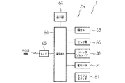
次に、図7に基づいて硬貨入出金装置1に内蔵される各部の電気的接続を説明する。硬貨入出金装置1は、各部の制御を受け持つ制御部64を備え、この制御部64にインターフェース(I/F)65を介してPOS端末が接続されている。制御部64は、ここでは特に図示しないが、各部を集中的に制御するCPU(Central Processing Unit)、制御プログラム等の固定的データを予め格納するROM(Read Only Memory)、金種別の硬貨Cの枚数等の可変的なデータを書換え自在に格納するRAM(Random Access Memory)等により構成されている。また、制御部64には、表示器62、スタートキーや終了キーなどの操作キー63も接続されている。   Next, the electrical connection of each part built in the coin depositing and dispensing apparatus 1 will be described with reference to FIG. The coin deposit / withdrawal apparatus 1 includes a control unit 64 that controls each unit, and a POS terminal is connected to the control unit 64 via an interface (I / F) 65. The control unit 64 is not particularly shown here, but a CPU (Central Processing Unit) that centrally controls each unit, a ROM (Read Only Memory) that stores fixed data such as a control program in advance, and a coin C of denomination It is composed of a RAM (Random Access Memory) or the like that stores variable data such as the number of sheets in a rewritable manner. The control unit 64 is also connected with a display 62 and operation keys 63 such as a start key and an end key.

さらに、制御部64には、投入センサ6、計数センサ31、払出センサ40、材質センサ41等のセンサ類66、シャッタソレノイド38、各モータM、マイクロスイッチ61等が接続されている。ここで、投入センサ6、計数センサ31、払出センサ40、材質センサ41等のセンサ類66は、例えば硬貨Cを光学的に検出した信号やコイルの電圧の変動等を制御部64に伝達するものであり、この検出信号に基づいて制御部64が各モータMを駆動制御する。また、マイクロスイッチ61は経路切替部材57に押されることにより検出信号を制御部64に伝達する。また、シャッタソレノイド38は、制御部64から出力される信号に基づき駆動制御され、通電(ON)されることで硬貨シャッタ39を払出ベルト35から離反する方向に変位させ、指定された枚数だけ硬貨Cを払い出す。なお、シャッタソレノイド38は、ここでは1つしか図示しないが、実際には各金種毎に個々に制御部64によって制御される。   Further, the control unit 64 is connected with sensors 66 such as the input sensor 6, the counting sensor 31, the payout sensor 40, the material sensor 41, the shutter solenoid 38, each motor M, the micro switch 61, and the like. Here, the sensors 66 such as the insertion sensor 6, the counting sensor 31, the payout sensor 40, and the material sensor 41 transmit, for example, a signal obtained by optically detecting the coin C, a fluctuation in coil voltage, and the like to the control unit 64. Based on this detection signal, the control unit 64 drives and controls each motor M. Further, the micro switch 61 transmits a detection signal to the control unit 64 when pressed by the path switching member 57. The shutter solenoid 38 is driven and controlled based on a signal output from the control unit 64, and is energized (ON) to displace the coin shutter 39 in a direction away from the payout belt 35. C is paid out. Although only one shutter solenoid 38 is shown here, in actuality, the control unit 64 individually controls each denomination.

このような構成において、回収袋101が装置本体2の回収袋取付部5のスライド部材71に取り付けられていない状態で、硬貨Cが硬貨投入口3に投入されると、投入センサ6がその硬貨Cを検出し、この検出信号により入金搬送ベルト14、投入口ローラ21、搬送ベルト24が駆動される。そして、硬貨投入口3に投入された硬貨Cは、入金搬送ベルト14と投入口ローラ21との間で1枚ずつ分離されて搬送される。入金搬送ベルト14により搬送される硬貨Cは、硬貨案内部22によって搬送方向が略直角に屈曲され、入金搬送ベルト14から搬送ベルト24に受け渡され、硬貨選別部7で金種毎の選別がなされる。すなわち、硬貨Cは、金種に応じて選別穴29から落下し、硬貨収納部8a〜8fに金種別に収納される。そして、選別穴29から落下した硬貨Cは、計数センサ31によりその数がカウントされる。   In such a configuration, when the coin C is inserted into the coin insertion slot 3 in a state where the collection bag 101 is not attached to the slide member 71 of the collection bag attachment portion 5 of the apparatus main body 2, the insertion sensor 6 detects the coin. C is detected, and the deposit conveyance belt 14, the inlet roller 21, and the conveyance belt 24 are driven by this detection signal. And the coin C thrown into the coin slot 3 is separated and conveyed one by one between the deposit conveyance belt 14 and the slot roller 21. The coin C conveyed by the deposit conveyance belt 14 is bent at a substantially right angle by the coin guide unit 22 and is transferred from the deposit conveyance belt 14 to the conveyance belt 24, and the coin sorting unit 7 sorts each denomination. Made. That is, the coin C falls from the sorting hole 29 according to the denomination and is stored in the coin storage units 8a to 8f by denomination. Then, the number of coins C falling from the sorting hole 29 is counted by the counting sensor 31.

また、硬貨待機部37に硬貨Cがない場合には、払出ベルト35が駆動されて硬貨待機部37に所定枚数(例えば4枚)の硬貨Cが常に存在するように動作制御がなされる。   When there is no coin C in the coin standby unit 37, the payout belt 35 is driven and operation control is performed so that a predetermined number (for example, four) of coins C is always present in the coin standby unit 37.

ついで、POS端末において締め処理がなされ、POS端末より硬貨Cの払出指令があった場合には、払出ベルト35が駆動されるとともに、金種毎に硬貨シャッタ39がシャッタソレノイド38によって駆動されるため、必要枚数の硬貨Cが送り出される。このとき、回収袋101が装置本体2の回収袋取付部5のスライド部材71に取り付けられていないので、経路切替部材57は払出位置に位置付けられており落下経路が払出経路51に設定されていることにより、払出ベルト35により送り出された硬貨Cは、硬貨案内面54に案内されて硬貨払出口4に払い出される。   Next, a tightening process is performed at the POS terminal, and when a payout command for coins C is issued from the POS terminal, the payout belt 35 is driven and the coin shutter 39 is driven by the shutter solenoid 38 for each denomination. The required number of coins C is sent out. At this time, since the collection bag 101 is not attached to the slide member 71 of the collection bag attachment portion 5 of the apparatus main body 2, the path switching member 57 is positioned at the payout position, and the drop path is set to the payout path 51. Thus, the coin C sent out by the payout belt 35 is guided to the coin guide surface 54 and is paid out to the coin payout outlet 4.

次に、装置本体のハウジング2d内に収納された全硬貨Cの一括回収作業の手順を説明する。まず、オペレータは、回収袋101を装置本体2のスライド部材71の嵌合部105に差し込んで回収袋101をスライド部材71に取り付け回収袋101を回収位置に移動させる。これにより、装置本体2において後述する硬貨Cの一括払出処理がなされ、硬貨Cが回収袋101に払い出される。オペレータは、回収袋101を装置手前に引き出し、装置本体2のハウジング2dに収納されていた全硬貨Cを収納した回収袋101をスライド部材71から取り外し硬貨Cを回収する。   Next, a procedure for collective collection of all coins C stored in the housing 2d of the apparatus main body will be described. First, the operator inserts the collection bag 101 into the fitting portion 105 of the slide member 71 of the apparatus main body 2, attaches the collection bag 101 to the slide member 71, and moves the collection bag 101 to the collection position. As a result, a collective payout process for coins C to be described later is performed in the apparatus main body 2, and the coins C are paid out to the collection bag 101. The operator pulls the collection bag 101 toward the front of the apparatus, removes the collection bag 101 containing all the coins C stored in the housing 2d of the apparatus body 2 from the slide member 71, and collects the coins C.

次に、図8に基づいて、このような一括回収作業の際に制御部64が行なう硬貨Cの一括払出処理を各部の動作とともに説明する。ここで、図8は硬貨Cの一括払出処理の流れを示すフローチャートである。なお、必要に応じて図5及び図6も適宜参照する。   Next, based on FIG. 8, the collective payout processing of coins C performed by the control unit 64 during such collective collection work will be described together with the operation of each unit. Here, FIG. 8 is a flowchart showing the flow of the collective payout process of coins C. In addition, FIG.5 and FIG.6 is also referred suitably as needed.

まず、回収袋101の装置本体2のハウジング2dへの取り付けの有無を検出する(ステップS1)。ここに、回収袋101のハウジング2dへの取り付けの有無を検出する取付検出手段の機能が実行される。回収袋101が取り付けられていない場合は、回収袋101が取り付けられるまで待機する(ステップS1のN)。   First, it is detected whether or not the collection bag 101 is attached to the housing 2d of the apparatus main body 2 (step S1). Here, the function of the attachment detection means for detecting whether or not the collection bag 101 is attached to the housing 2d is executed. When the collection bag 101 is not attached, it waits until the collection bag 101 is attached (N of step S1).

オペレータにより回収袋101がスライド部材71に保持されて回収位置に位置付けられて、マイクロスイッチ61が押され(図6参照)、マイクロスイッチ61から検出信号が入力され、これにより、回収袋101が装置本体2のハウジング2dに取り付けられたと判断した場合には(ステップS1のY)、払出ベルト35を回転駆動して装置本体2のハウジング2dに収納されている全硬貨Cの払出を開始する(ステップS2)。ここで、マイクロスイッチ61の検出信号が一括払出指令として機能する。なお、この払出は、回収袋101によってマイクロスイッチ61が押されてから、直ちに開始しても良いし、規定時間(例えば、2秒)後に開始してもよい。   The collection bag 101 is held by the operator on the slide member 71 and positioned at the collection position by the operator, the micro switch 61 is pressed (see FIG. 6), and a detection signal is input from the micro switch 61. If it is determined that it is attached to the housing 2d of the main body 2 (Y in step S1), the payout belt 35 is rotationally driven to start paying out all coins C stored in the housing 2d of the apparatus main body 2 (step S1). S2). Here, the detection signal of the microswitch 61 functions as a batch payout command. This payout may be started immediately after the microswitch 61 is pushed by the collection bag 101, or may be started after a specified time (for example, 2 seconds).

このとき、回収袋101により経路切替部材57が払出位置から回収位置へ回動され、回収経路52が回収袋101に連通する。これにより、払出ベルト35により送り出される硬貨Cは、硬貨案内孔55によって形成された回収経路52に沿って落下し、回収袋101に収納される。   At this time, the path switching member 57 is rotated from the payout position to the recovery position by the recovery bag 101, and the recovery path 52 communicates with the recovery bag 101. As a result, the coin C fed out by the payout belt 35 falls along the collection path 52 formed by the coin guide hole 55 and is stored in the collection bag 101.

そして、装置本体2のハウジング2dに収納されている全硬貨Cの払出が完了した場合には(ステップS3のY)、払出ベルト35の駆動を停止して(ステップS4)、処理を終了する。ここに、ステップS2〜ステップS4によって、一括払出手段の機能が実行される。   When the payout of all coins C stored in the housing 2d of the apparatus main body 2 is completed (Y in Step S3), the drive of the payout belt 35 is stopped (Step S4), and the process is terminated. Here, the function of the collective payout means is executed in steps S2 to S4.

ここで、硬貨Cの一括払出中に、オペレータの誤操作などにより回収袋101が回収位置から装置手前側に移動され回収袋101によるマイクロスイッチ61の押し状態が解除され(図5参照)、これにより、回収袋101が装置本体2のハウジング2dから取り外されたと判断した場合には(ステップS5)、払出ベルト35の駆動を停止して(ステップS4)、処理を終了する。これにより、硬貨Cの一括払出中に回収袋101が取り外された場合の装置外への硬貨Cの散乱が防止される。   Here, during the collective dispensing of the coins C, the collection bag 101 is moved from the collection position to the front side of the apparatus by an operator's erroneous operation or the like, and the push state of the microswitch 61 by the collection bag 101 is released (see FIG. 5). When it is determined that the collection bag 101 has been removed from the housing 2d of the apparatus main body 2 (step S5), the driving of the payout belt 35 is stopped (step S4), and the process ends. Thereby, scattering of the coin C to the outside of the apparatus when the collection bag 101 is removed during the collective dispensing of the coin C is prevented.

なお、このような硬貨Cの一括払出処理において、硬貨Cの払出中に終了キーが操作された場合には、硬貨Cの払い出しを中止するようにしても良い。   In such a collective payout process of coins C, if the end key is operated during the payout of the coins C, the payout of the coins C may be stopped.

このような硬貨Cの一括回収作業における硬貨Cの一括払出動作での払出ベルト35に対する清掃動作について説明する。硬貨Cの一括払出動作において、回収袋101がスライド部材71に取り付けられて回収位置に位置付けられると、スライド部材71により押された保持体83が回動してブラシ81が清掃位置に位置して払出ベルト35の下側の外周面35aに当接する。この状態で払出ベルト35が回転駆動されるので、ブラシ81に対して払出ベルト35が摺動し、払出ベルト35の外周面35aの清掃が行われる。   The cleaning operation for the payout belt 35 in the collective payout operation of the coins C in the collective collection operation of the coins C will be described. In the collective dispensing operation of coins C, when the collection bag 101 is attached to the slide member 71 and positioned at the collection position, the holding body 83 pushed by the slide member 71 rotates and the brush 81 is positioned at the cleaning position. It contacts the lower outer peripheral surface 35 a of the payout belt 35. Since the payout belt 35 is rotationally driven in this state, the payout belt 35 slides with respect to the brush 81, and the outer peripheral surface 35a of the payout belt 35 is cleaned.

一括払出動作の終了とともに、回収袋101の取り外しのためにスライド部材71に取り付けられた回収袋101がスライド部材とともに装置手前に引き出されることにより、スライド部材71からの押圧が解除された保持体83は、保持体83とブラシ81との自重により回動し、これにより、ブラシ81が離反位置に位置し、ブラシ81が払出ベルト35から離反する。   With the end of the collective payout operation, the collection bag 101 attached to the slide member 71 for removing the collection bag 101 is pulled out together with the slide member to the front of the apparatus, whereby the holding body 83 from which the pressure from the slide member 71 is released. Is rotated by its own weight between the holding body 83 and the brush 81, whereby the brush 81 is located at the separation position and the brush 81 is separated from the payout belt 35.

そして、オペレータにより回収袋101が取り外されてカバー74が閉じ位置に位置付けられて作業が終了するが、この状態において、スライド部材71は保持体83に当接しないので、ブラシ81の払出ベルト35からの離反状態が維持される。   Then, the collection bag 101 is removed by the operator and the cover 74 is positioned at the closed position, and the operation is completed. In this state, the slide member 71 does not come into contact with the holding body 83, and therefore, from the payout belt 35 of the brush 81. The separated state is maintained.

以上説明したように、本実施の形態では、硬貨Cの一括回収作業における硬貨Cの一括払出動作に連動させて、ブラシ81による払出ベルト35の清掃を実行するので、ユーザに払出ベルト35の清掃を意識させることなく払出ベルト35の清掃が実行される。また、硬貨Cの一括回収作業は、一般的に一日に一回程度定期的に行われるので、払出ベルト35の清掃が定期的に行われることになる。ここで、例えば、払出ベルト35を清掃するためにブラシ81を常時払出ベルト35に当接させた場合には、払出ベルト35及びブラシ81がすぐに傷んでしまい問題となるが、本実施の形態では、ブラシ81の払出ベルト35への当接は、硬貨Cの一括回収作業における硬貨の一括払出動作に連動させているので、上述したように一般的に一日に一回程度であり、払出ベルト35及びブラシ81の長寿命化が図られている。   As described above, in the present embodiment, since the payout belt 35 is cleaned by the brush 81 in conjunction with the collective payout operation of the coins C in the collective collection operation of the coins C, the user cleans the payout belt 35. The payout belt 35 is cleaned without being aware of the above. In addition, since the collective collection of coins C is generally performed regularly about once a day, the payout belt 35 is periodically cleaned. Here, for example, when the brush 81 is always brought into contact with the payout belt 35 in order to clean the payout belt 35, the payout belt 35 and the brush 81 are damaged immediately. Then, since the contact of the brush 81 with the payout belt 35 is interlocked with the collective coin dispense operation in the collective collection operation of the coins C, it is generally only once a day as described above. The life of the belt 35 and the brush 81 is extended.

また、本実施の形態においては、払出ベルト35は、硬貨払出口4に硬貨Cを落下させて払い出し、硬貨払出口4及び払出ベルト35が設けられたハウジング2dと、払出ベルト35から落下する硬貨Cの落下経路を払出ベルト35から落下する硬貨Cを硬貨払出口4に案内する払出経路51に設定する払出位置と、落下経路を払出ベルト35から落下する硬貨Cを硬貨払出口4とは異なる場所に案内する回収経路52に設定する回収位置と、の間でハウジング2dに対して移動自在に設けられた経路切替部材57と、上面開口であって、ハウジング2dに対して着脱自在に設けられ、ハウジング2dに取り付けられた状態で回収経路52の下端側に上面が連通する位置に位置付けられ硬貨Cを収納する回収体である回収袋101と、回収袋101がハウジング2dに取り付けられていない場合に、経路切替部材57を払出位置に位置付ける第三の位置付け手段であるコイルバネ58と、回収袋101がハウジング2dに取り付けられるのに連動して経路切替部材57を回収位置に移動させる移動手段と、回収袋101のハウジング2dへの取り付けの有無を検出する取付検出手段と、を備え、一括払出手段は、回収袋101がハウジング2dへ取り付けられたことを取付検出手段が検出し、かつ、一括払出指令が有った場合に硬貨Cを払い出すことにより、硬貨入出金装置1のハウジング2d内に収納されている全ての硬貨Cを回収袋101に一括回収する際には、回収袋101を装置本体2に取り付けるだけで、払い出される硬貨Cが回収袋101に落下するようになり、硬貨入出金装置1に収納されている硬貨Cを一括回収する際の一括回収作業を容易に行える。   Further, in the present embodiment, the payout belt 35 drops the coin C to the coin payout outlet 4 and pays out the housing 2d provided with the coin payout outlet 4 and the payout belt 35, and the coin falling from the payout belt 35. The payout position at which the coin C falling from the payout belt 35 is set to the payout path 51 for guiding the coin C falling from the payout belt 35 to the coin payout outlet 4 is different from the coin payout opening 4 at the coin C falling from the payout belt 35 through the drop path. A path switching member 57 provided so as to be movable with respect to the housing 2d between the collection position set in the collection path 52 guided to the place, and an upper surface opening, which is provided detachably with respect to the housing 2d. A recovery bag 101 that is a recovery body that stores coins C and is positioned at a position where the upper surface communicates with the lower end side of the recovery path 52 in a state of being attached to the housing 2d; When 01 is not attached to the housing 2d, the path switching member 57 is interlocked with the coil spring 58 as the third positioning means for positioning the path switching member 57 at the payout position and the collection bag 101 being attached to the housing 2d. Moving means for moving the collection bag 101 to the collection position, and attachment detection means for detecting whether or not the collection bag 101 is attached to the housing 2d. The collective dispensing means is attached to indicate that the collection bag 101 is attached to the housing 2d. All coins C stored in the housing 2d of the coin depositing / dispensing device 1 are collected in a collection bag 101 by paying out coins C when the detection means detects and there is a collective payout command. When the collecting bag 101 is attached to the apparatus main body 2, the coin C to be paid out falls into the collecting bag 101. Easily bulk recovery operations at the time of bulk collecting the coins C that are stored in dispensing device 1.

また、本実施の形態においては、第三の位置付け手段は、経路切替部材57が払出位置に位置するように経路切替部材57を付勢する付勢部材であるコイルバネ58であり、移動手段は、回収体である回収袋101であって、回収袋101は、ハウジング2dに対してスライド移動自在に設けられハウジング2dにスライド移動で取り付けられるのに連動して経路切替部材57が回収位置に位置するように経路切替部材57を押すことにより、コイルバネ58の力に抗して回収袋101をスライド移動でハウジング2dに取り付けるだけで、回収経路52を回収袋101に連通させることができる。   In the present embodiment, the third positioning means is a coil spring 58 that is an urging member that urges the path switching member 57 so that the path switching member 57 is positioned at the payout position. The collection bag 101 is a collection body, and the collection bag 101 is provided slidably with respect to the housing 2d, and the path switching member 57 is positioned at the collection position in conjunction with being slidably attached to the housing 2d. By pushing the path switching member 57 in this manner, the collection path 52 can be communicated with the collection bag 101 simply by attaching the collection bag 101 to the housing 2d by sliding movement against the force of the coil spring 58.

また、本実施の形態においては、清掃部材であるブラシ81は、支軸82を中心に回動自在に設けられブラシ81を清掃位置と離反位置との間で移動自在とする保持体83に保持され、回収体である回収袋101のスライド移動に連動してハウジング2dに対してスライド移動し、回収袋101が回収経路52の下端側に上面が連通する位置に位置付けられるのに連動して保持体83を回動させてブラシ81を清掃位置に位置付け、第一の位置付け手段として機能するスライド部材71を備えることにより、回収袋101のセットに連動してブラシ81を払出ベルト35に当接させることができる。   Further, in the present embodiment, the brush 81 that is a cleaning member is held by a holding body 83 that is provided so as to be rotatable about a support shaft 82 and is movable between a cleaning position and a separation position. In response to the sliding movement of the collection bag 101, which is a collection body, the slide is moved relative to the housing 2d, and the collection bag 101 is held in conjunction with the upper surface being positioned at the lower end side of the collection path 52. By rotating the body 83 to position the brush 81 at the cleaning position and providing the slide member 71 functioning as a first positioning means, the brush 81 is brought into contact with the delivery belt 35 in conjunction with the set of the collection bag 101. be able to.

また、本実施の形態においては、第二の位置付け手段は、清掃部材であるブラシ81と保持体83との自重であることにより、第二の位置付け手段を簡単に実現することができる。   In the present embodiment, the second positioning means can be easily realized by the self-weight of the brush 81 as the cleaning member and the holding body 83.

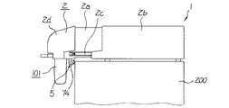
また、本実施の形態においては、例えば、図9に示すように、装置本体2がハウジング2dの前端を設置台200の端に揃えられて設置台200上に設置された場合には、回収袋取付部5の下方に設置台200が位置するので、このままでは回収袋101を回収袋取付部5に取り付けることができないが、図3に示すように、入出金機構ユニット2aをユニット保持ケース2bから引き出すことによって、回収袋取付部5の下方に空間ができるので、回収袋101を回収袋取付部5に取り付けることができる。   In the present embodiment, for example, as shown in FIG. 9, when the apparatus main body 2 is installed on the installation table 200 with the front end of the housing 2d aligned with the end of the installation table 200, the collection bag Since the installation base 200 is located below the attachment portion 5, the collection bag 101 cannot be attached to the collection bag attachment portion 5 as it is. However, as shown in FIG. 3, the deposit / withdrawal mechanism unit 2a is removed from the unit holding case 2b. By pulling out, a space is created below the collection bag attachment portion 5, so that the collection bag 101 can be attached to the collection bag attachment portion 5.

なお、本実施の形態では、硬貨Cの一括払出処理において、回収袋101がハウジング2dに取り付けられたのを条件に硬貨Cの払い出しを開始したが、硬貨Cの払い出しの条件としては、次のような変形例を挙げることができる。即ち、回収袋101がハウジング2dに取り付けられたのを条件とし、その後、図示しないスタートキーが操作された場合に、硬貨Cの払い出しを開始するというものである。   In the present embodiment, in the collective payout process for coins C, the payout of coins C is started on the condition that the collection bag 101 is attached to the housing 2d. Such a modification can be given. That is, on the condition that the collection bag 101 is attached to the housing 2d, after that, when a start key (not shown) is operated, the payout of the coin C is started.

また、本実施の形態では、硬貨Cの一括払出処理において、硬貨収納部8に収納されている全ての硬貨Cの払い出しを実行する例を説明したが、これに限るものではなく、硬貨収納部8に収納されている硬貨Cのうちの少なくとも一つの金種の硬貨Cを全て払い出すようにしてよい。このときには、例えば、一括払出をする硬貨Cの金種を指定する金種指定キー(図示せず)を設ける。そして、回収袋101がハウジング2dに取り付けられたのを条件とし、その後、金種指定キーが操作された場合に、操作された金種指定キーに対応する金種の硬貨Cを全て払い出すようにすればよい。   In the present embodiment, the example in which the payout of all the coins C stored in the coin storage unit 8 is executed in the collective payout process of the coins C is not limited to this. All of the coins C of at least one denomination among the coins C stored in 8 may be paid out. At this time, for example, a denomination designation key (not shown) for designating the denomination of the coin C to be paid out at once is provided. Then, on condition that the collection bag 101 is attached to the housing 2d, when the denomination designation key is operated thereafter, all the coins C of the denomination corresponding to the operated denomination designation key are paid out. You can do it.

本発明の一実施の形態の硬貨入出金装置の外観を示す斜視図である。It is a perspective view which shows the external appearance of the coin depositing / withdrawing apparatus of one embodiment of this invention. 回収袋が装置本体に取り付けられた状態の硬貨入出金装置の外観を示す斜視図である。It is a perspective view which shows the external appearance of the coin depositing / withdrawing apparatus in the state in which the collection bag was attached to the apparatus main body. 設置台上に設置され入出金機構ユニットがユニット保持ケースから引き出された状態の硬貨入出金装置を示す側面図である。It is a side view which shows the coin depositing / withdrawing apparatus of the state installed on the installation stand and withdrawing / withdrawing mechanism unit pulled out from the unit holding case. 入出金機構ユニットの内部構造を示す平面図である。It is a top view which shows the internal structure of a deposit or withdrawal mechanism unit. 入出金機構ユニットの内部構造を示す縦断側面図である。It is a vertical side view which shows the internal structure of a deposit or withdrawal mechanism unit. 回収袋が取付部に取り付けられた状態の入出金機構ユニットの内部構造を示す縦断側面図である。It is a vertical side view which shows the internal structure of the deposit or withdrawal mechanism unit in the state where the collection bag is attached to the attachment part. 硬貨入出金装置に内蔵される各部の電気的接続を示すブロック図である。It is a block diagram which shows the electrical connection of each part incorporated in a coin depositing / withdrawing apparatus. 硬貨の一括払出処理の流れを示すフローチャートである。It is a flowchart which shows the flow of the collective payment process of a coin. 装置本体のハウジングの前端を設置台の端に揃えられて設置台上に設置された硬貨入出金装置を示す側面図である。It is a side view which shows the coin depositing and dispensing apparatus installed on the installation stand by aligning the front end of the housing of the apparatus main body with the end of the installation stand.

符号の説明Explanation of symbols

1…硬貨入出金装置、2d…ハウジング、4…硬貨払出口、8…硬貨収納部、35…払出ベルト、35a…外周面、51…払出経路、52…回収経路、57…経路切替部材、58…コイルバネ(第三の位置付け手段、付勢部材)、71…スライド部材(第一の位置付け手段)、81…ブラシ(清掃部材)、82…支軸、83…保持体、101…回収袋(回収体、移動手段)、C…硬貨、ステップS1…取付検出手段、ステップS2〜ステップS4…一括払出手段

DESCRIPTION OF SYMBOLS 1 ... Coin depositing / withdrawing apparatus, 2d ... Housing, 4 ... Coin payment exit, 8 ... Coin storage part, 35 ... Discharge belt, 35a ... Outer peripheral surface, 51 ... Discharge path | route, 52 ... Collection | recovery path | route 57 ... Path | route switching member, 58 ... Coil spring (third positioning means, biasing member), 71 ... Slide member (first positioning means), 81 ... Brush (cleaning member), 82 ... Support shaft, 83 ... Holding body, 101 ... Collection bag (collection) Body, moving means), C ... coin, step S1 ... attachment detecting means, step S2 to step S4 ... collective paying means

Claims (4)

硬貨収納部に金種別に収納した硬貨を払出ベルトにより搬送して硬貨払出口に払い出す硬貨入出金装置において、
一括払出指令に応じて前記硬貨収納部に収納されている硬貨のうちの少なくとも一つの金種の硬貨を全て払い出すために前記払出ベルトを駆動する一括払出手段と、
前記払出ベルトの外周面に当接して前記払出ベルトの外周面を清掃する清掃位置と前記払出ベルトから離反する離反位置との間で移動自在に設けられた清掃部材と、
前記一括払出手段による硬貨の払い出しに伴って、前記清掃部材を前記清掃位置に位置付ける第一の位置付け手段と、
前記一括払出手段による硬貨の払い出しが行われないときに、前記清掃部材を前記離反位置に位置付ける第二の位置付け手段と、
を備えることを特徴とする硬貨入出金装置。
In the coin depositing and dispensing device that conveys the coins stored in the coin storage unit by denomination by the dispensing belt and pays out to the coin dispensing outlet,
Collective dispensing means for driving the dispensing belt to dispense all coins of at least one denomination of coins stored in the coin storage unit in response to a collective dispensing command;
A cleaning member provided movably between a cleaning position that contacts the outer peripheral surface of the payout belt and cleans the outer peripheral surface of the payout belt, and a separation position that moves away from the payout belt;
A first positioning means for positioning the cleaning member at the cleaning position in accordance with the payout of coins by the collective paying means;
A second positioning means for positioning the cleaning member at the separation position when coins are not paid out by the collective paying means;
A coin depositing and dispensing apparatus comprising:
前記払出ベルトは、前記硬貨払出口に硬貨を落下させて払い出し、
前記硬貨払出口及び前記払出ベルトが設けられたハウジングと、
前記払出ベルトから落下する硬貨の落下経路を前記払出ベルトから落下する硬貨を前記硬貨払出口に案内する払出経路に設定する払出位置と、前記落下経路を前記払出ベルトから落下する硬貨を前記硬貨払出口とは異なる場所に案内する回収経路に設定する回収位置と、の間で前記ハウジングに対して移動自在に設けられた経路切替部材と、
上面開口であって、前記ハウジングに対して着脱自在に設けられ、前記ハウジングに取り付けられた状態で前記回収経路の下端側に前記上面が連通する位置に位置付けられ硬貨を収納する回収体と、
前記回収体が前記ハウジングに取り付けられていない場合に、前記経路切替部材を前記払出位置に位置付ける第三の位置付け手段と、
前記回収体が前記ハウジングに取り付けられるのに連動して前記経路切替部材を前記回収位置に移動させる移動手段と、
前記回収体の前記ハウジングへの取り付けの有無を検出する取付検出手段と、
を備え、
前記一括払出手段は、前記回収体が前記ハウジングへ取り付けられたことを前記取付検出手段が検出し、かつ、前記一括払出指令が有った場合に硬貨を払い出す、ことを特徴とする請求項1記載の硬貨入出金装置。
The payout belt drops and pays out coins at the coin payout exit,
A housing provided with the coin dispensing outlet and the dispensing belt;
A payout position for setting a falling path of coins falling from the payout belt to a payout path for guiding coins falling from the payout belt to the coin payout outlet, and a coin falling from the payout belt to the coins falling from the payout belt. A path switching member provided movably with respect to the housing between a recovery position set in a recovery path for guiding to a different place from the outlet;
A recovery body that is an upper surface opening, is provided detachably with respect to the housing, and is positioned at a position where the upper surface communicates with a lower end side of the recovery path in a state of being attached to the housing;
A third positioning means for positioning the path switching member at the payout position when the collection body is not attached to the housing;
Moving means for moving the path switching member to the collection position in conjunction with the collection body being attached to the housing;
An attachment detecting means for detecting whether or not the recovered body is attached to the housing;
With
The collective paying means is characterized in that the attachment detecting means detects that the collection body is attached to the housing, and pays out coins when the collective payout command is issued. 1. Coin depositing / withdrawing apparatus according to 1.
前記第三の位置付け手段は、前記経路切替部材が前記払出位置に位置するように前記経路切替部材を付勢する付勢部材であり、
前記移動手段は、前記回収体であって、
前記回収体は、前記ハウジングに対してスライド移動自在に設けられ前記ハウジングにスライド移動で取り付けられるのに連動して前記経路切替部材が前記回収位置に位置するように前記経路切替部材を押す、ことを特徴とする請求項2記載の硬貨入出金装置。
The third positioning means is a biasing member that biases the path switching member so that the path switching member is located at the payout position.
The moving means is the collection body,
The collection body is provided slidably with respect to the housing, and pushes the path switching member so that the path switching member is located at the collection position in conjunction with being slidably attached to the housing. The coin depositing / withdrawing apparatus according to claim 2.
前記清掃部材は、支軸を中心に回動自在に設けられ前記清掃部材を前記清掃位置と前記離反位置との間で移動自在とする保持体に保持され、
前記回収体のスライド移動に連動して前記ハウジングに対してスライド移動し、前記回収体が前記回収経路の下端側に前記上面が連通する位置に位置付けられるのに連動して前記保持体を回動させて前記清掃部材を前記清掃位置に位置付け、前記第一の位置付け手段として機能するスライド部材を備える、ことを特徴とする請求項2又は3記載の硬貨入出金装置。
The cleaning member is rotatably provided around a support shaft and is held by a holding body that allows the cleaning member to move between the cleaning position and the separation position.
The holder is slid relative to the housing in conjunction with the slide movement of the recovery body, and the holding body is rotated in conjunction with the recovery body being positioned at a position where the upper surface communicates with the lower end side of the recovery path. 4. The coin depositing / withdrawing apparatus according to claim 2, further comprising a slide member that positions the cleaning member at the cleaning position and functions as the first positioning unit. 5.
JP2003289654A 2003-08-08 2003-08-08 Coin deposit / withdrawal device Expired - Fee Related JP3818515B2 (en)

Priority Applications (1)

Application Number Priority Date Filing Date Title
JP2003289654A JP3818515B2 (en) 2003-08-08 2003-08-08 Coin deposit / withdrawal device

Applications Claiming Priority (1)

Application Number Priority Date Filing Date Title
JP2003289654A JP3818515B2 (en) 2003-08-08 2003-08-08 Coin deposit / withdrawal device

Publications (2)

Publication Number Publication Date
JP2005062995A true JP2005062995A (en) 2005-03-10
JP3818515B2 JP3818515B2 (en) 2006-09-06

Family

ID=34367904

Family Applications (1)

Application Number Title Priority Date Filing Date
JP2003289654A Expired - Fee Related JP3818515B2 (en) 2003-08-08 2003-08-08 Coin deposit / withdrawal device

Country Status (1)

Country Link
JP (1) JP3818515B2 (en)

Cited By (3)

* Cited by examiner, † Cited by third party
Publication number Priority date Publication date Assignee Title
JP2007185217A (en) * 2006-01-11 2007-07-26 Olympia:Kk Token dispenser
WO2007114361A1 (en) * 2006-04-04 2007-10-11 Glory Ltd. Coin receiving/dispensing machine
JP2018112823A (en) * 2017-01-10 2018-07-19 グローリー株式会社 Currency processing machine

Cited By (4)

* Cited by examiner, † Cited by third party
Publication number Priority date Publication date Assignee Title
JP2007185217A (en) * 2006-01-11 2007-07-26 Olympia:Kk Token dispenser
WO2007114361A1 (en) * 2006-04-04 2007-10-11 Glory Ltd. Coin receiving/dispensing machine
US8961275B2 (en) 2006-04-04 2015-02-24 Glory Ltd. Coin depositing and dispensing machine
JP2018112823A (en) * 2017-01-10 2018-07-19 グローリー株式会社 Currency processing machine

Also Published As

Publication number Publication date
JP3818515B2 (en) 2006-09-06

Similar Documents

Publication Publication Date Title
JP5592918B2 (en) Money dispensing device and banknote dispensing device
WO2006070606A1 (en) Coin dispenser
EP3079124B1 (en) Coin package discharge device
JP2013033409A (en) Coin receiving and dispensing device
JP4107510B2 (en) Coin deposit / withdrawal device
JP3818515B2 (en) Coin deposit / withdrawal device
JP2009059307A (en) Coin depositing/dispensing machine
WO2007114361A1 (en) Coin receiving/dispensing machine
JP2007226631A (en) Coin processing apparatus
JP3673052B2 (en) Trading unit of coin depositing and dispensing machine
JP3932537B2 (en) Coin deposit / withdrawal device
JP2004199626A (en) Coin depositing/dispensing device
JP3658530B2 (en) Card feeding device
JP2009059308A (en) Coin depositing/dispensing machine
JP2004199593A (en) Coin depositing and dispensing device
JP2004302503A (en) Paper money receiving/dispensing apparatus
JP2001034839A (en) Automatic change dispenser
JP7447727B2 (en) Coin handling equipment and coin handling equipment
JP3889539B2 (en) Card issuing device
JP7178387B2 (en) money handling equipment
JPH0962896A (en) Foreign matter removing method for automatic cash transaction device
KR100377030B1 (en) Device for receiving and disbursing paper money
JPH11134535A (en) Coin receiving/dispensing device
JP2001283279A (en) Coin processor
JP3510076B2 (en) Coin depositing device

Legal Events

Date Code Title Description
A977 Report on retrieval

Free format text: JAPANESE INTERMEDIATE CODE: A971007

Effective date: 20060524

TRDD Decision of grant or rejection written
A01 Written decision to grant a patent or to grant a registration (utility model)

Free format text: JAPANESE INTERMEDIATE CODE: A01

Effective date: 20060607

A61 First payment of annual fees (during grant procedure)

Free format text: JAPANESE INTERMEDIATE CODE: A61

Effective date: 20060608

R150 Certificate of patent or registration of utility model

Free format text: JAPANESE INTERMEDIATE CODE: R150

FPAY Renewal fee payment (event date is renewal date of database)

Free format text: PAYMENT UNTIL: 20090623

Year of fee payment: 3

FPAY Renewal fee payment (event date is renewal date of database)

Free format text: PAYMENT UNTIL: 20100623

Year of fee payment: 4

FPAY Renewal fee payment (event date is renewal date of database)

Free format text: PAYMENT UNTIL: 20100623

Year of fee payment: 4

FPAY Renewal fee payment (event date is renewal date of database)

Free format text: PAYMENT UNTIL: 20110623

Year of fee payment: 5

FPAY Renewal fee payment (event date is renewal date of database)

Free format text: PAYMENT UNTIL: 20120623

Year of fee payment: 6

FPAY Renewal fee payment (event date is renewal date of database)

Free format text: PAYMENT UNTIL: 20130623

Year of fee payment: 7

FPAY Renewal fee payment (event date is renewal date of database)

Free format text: PAYMENT UNTIL: 20130623

Year of fee payment: 7

FPAY Renewal fee payment (event date is renewal date of database)

Free format text: PAYMENT UNTIL: 20140623

Year of fee payment: 8

LAPS Cancellation because of no payment of annual fees