JP2005051337A - Image processing method, image processing apparatus, and program - Google Patents
Image processing method, image processing apparatus, and program Download PDFInfo
- Publication number
- JP2005051337A JP2005051337A JP2003203461A JP2003203461A JP2005051337A JP 2005051337 A JP2005051337 A JP 2005051337A JP 2003203461 A JP2003203461 A JP 2003203461A JP 2003203461 A JP2003203461 A JP 2003203461A JP 2005051337 A JP2005051337 A JP 2005051337A
- Authority
- JP
- Japan
- Prior art keywords
- signal
- value
- pixel
- bits
- original signal
- Prior art date
- Legal status (The legal status is an assumption and is not a legal conclusion. Google has not performed a legal analysis and makes no representation as to the accuracy of the status listed.)
- Withdrawn
Links
- 238000003672 processing method Methods 0.000 title claims description 6
- 238000006243 chemical reaction Methods 0.000 claims description 11
- 238000010586 diagram Methods 0.000 description 13
- 238000013139 quantization Methods 0.000 description 9
- 238000000034 method Methods 0.000 description 7
- 230000000694 effects Effects 0.000 description 2
- 230000015572 biosynthetic process Effects 0.000 description 1
- 230000007423 decrease Effects 0.000 description 1
- 239000002245 particle Substances 0.000 description 1
Images


Landscapes
- Image Processing (AREA)
- Facsimile Image Signal Circuits (AREA)
Abstract
Description
【0001】
【発明の属する技術分野】
本発明はデジタル画像信号の階調処理におけるトーンジャンプの発生を防止する画像処理方法および装置に関するものである。
【0002】
【従来の技術】
従来、デジタルカメラで撮影して得た画像や、CRやMRI等で撮影して得た医用画像等のデジタル画像を再生する場合には、CCDによる特性のバラツキ補正処理、濃度変換、階調処理等の各種の画像処理が施されて注目する画像を見えやすくするように加工が行われる。
【0003】
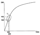
このような画像処理のうち階調処理では、図12に示すような横軸から縦軸への変換特性を持つルックアップテーブルを用いて階調の変換が行なわれるが、階調カーブが急に変化する部分Lのようなところではトーンジャンプが発生しやすいという問題がある。特に、階調処理を行う原画像の分解能が十分でない場合には(例えば、256階調から256階調に変換)、原画像では1階調しか違わない画素値が階調処理後には3階調違う画素値になるため(部分L)、なだらかに変化しているはずのグラデーション領域に色/濃度が急に変化するところが現れ、その変化が目立つようになる。それによって、輪郭のないところに輪郭があるように見える場合もある(偽輪郭という)。
【0004】
そこで、デジタル信号の分解能を上げて発生するトーンジャンプや偽輪郭を軽減する方法として、デジタル画像信号の最下位桁部分(例えば、下2桁)に、乱数発生回路を用いて発生させた乱数信号のデータを付加することにより軽減するものや(例えば、特許文献1)、最下位桁部分に付加するデータに写真フィルムの粒子上のノイズを利用することにより、乱数を付加する場合と同様の効果を得られるようにしたものがある。(例えば、特許文献2)
あるいは、周囲の画素値を合算して見かけ上の有効ビット数を増やしてトーンジャンプや偽輪郭を軽減する手法も用いられてきた。
【0005】
【特許文献1】
特開平6−203148号公報
【0006】
【特許文献2】
特開平10−13673号公報
【0007】
【発明が解決しようとする課題】
上述のように、乱数などを利用してビットを付加する手法では、一様にぼかすことでトーンジャンプによる段差を見えにくくすることは可能であったが、周囲の画素との関連が考慮されていないため、なだらかに階調が変化していくようなグラデーション領域で分解能を上げてもその変化に沿って階調を変化させていくことはできなかった。
【0008】
一方、周囲の画素値を合算して見かけ上の有効ビット数を増やす手法では、なだらかに階調が変化していくようなところはその変化に沿って階調を変化させることが可能となるが、画像全体を周囲の画素値に近づくようにぼかすことになり、本来の元の画像の画素値が急激に変化するようなところ(例えば、輪郭のようなエッジがあるところ)も周囲の画素値に影響されてぼけた画像となるという問題があった。
【0009】
そこで、本発明はこの課題に鑑みて、トーンジャンプの発生を抑制することができ、必要以上に画像をぼかすことのないような画像処理装置を提供することを目的とするものである。
【0010】
【課題を解決するための手段】
本発明の画像処理方法は、デジタル画像の各画素をNビットで表した原信号の値の最下位桁にnビットを増やすことにより信号ビット数をM(M=N+n)ビットに拡張してビット分解能を向上させた拡張信号に変換する画像処理方法において、
該画素の原信号の値と該画素の近傍数画素の画素値の平均値との差によって定まる補正値を該原信号に加えて前記各画素の原信号の値の精度を上げた推定信号を求めるステップと、
該推定信号の値を2n倍した後、下位桁を丸めて上位桁Mビットの前記拡張信号に変換してデジタル画像を形成するステップとを備え、
前記補正値が、前記推定信号の下位桁を丸めたとき原信号の値に戻るような値に決められていることを特徴とするものである。
【0011】
また、本発明の画像処理装置は、デジタル画像の各画素をNビットで表した原信号の値の最下位桁にnビットを増やすことにより信号ビット数をM(M=N+n)ビットに拡張してビット分解能を向上させた拡張信号に変換する画像処理装置において、
該画素の原信号の値と該画素の近傍数画素の画素値の平均値との差によって定まる補正値を該原信号に加えて前記各画素の原信号の値の精度を上げた推定信号を求める推定手段と、
該推定信号の値を2n倍した後、下位桁を丸めて上位桁Mビットの前記拡張信号に変換してデジタル画像を形成する画像形成手段とを備え、
前記補正値が、前記推定信号の下位桁を丸めたとき原信号の値に戻るような値に決められていることを特徴とするものである。
【0012】
また、本発明のプログラムは、デジタル画像の各画素をNビットで表した原信号の値の最下位桁にnビットを増やすことにより信号ビット数をM(M=N+n)ビットに拡張してビット分解能を向上させた拡張信号に変換する画像処理をコンピュータで実行させるためのプログラムにおいて、
該画素の原信号の値と該画素の近傍数画素の画素値の平均値との差によって定まる補正値を該原信号に加えて前記各画素の原信号の値の精度を上げた推定信号を求めるステップと、
該推定信号の値を2n倍した後、下位桁を丸めて上位桁Mビットの前記拡張信号に変換してデジタル画像を形成するステップとを実行させるためのプログラムであって、
前記補正値が、前記推定信号の下位桁を丸めたとき原信号の値に戻るような値に決められていることを特徴とするものである。
【0013】
「画素をNビットで表した原信号の値の最下位桁にnビットを増やすことによりM(M=N+n)ビットに拡張してビット分解能を向上させる」とは、各画素が持つ画素値を表すビットの最下位の桁のビットを追加することにより、元の階調では1つの画素値に量子化されたものが複数個の画素値で表せるように分解能を向上させることである。例えば、画像データの画素値を256階調で表す場合には8(N)ビット必要であるが、分解能を上げて画素値を1024階調で表そうとすると10(M)ビットが必要となる。そこで、8ビットで表されている画素値の最下位桁に2(n)ビット増やして10ビットにすることにより、元の8ビットでは1つの画素値で表されたものが細かく分かれた4つの画素値で表される。
【0014】
また、「原信号の値の精度を上げた推定信号」とは、具体的には、原信号の階調が8ビットの整数で表されていたものを例えば浮動小数点にして有効桁数が8ビット以上となるような数値で表された信号である。有効桁数が8ビット以上となるような数値であれば浮動小数点でなくても桁数の多い整数に変換してもよい。
【0015】
また、「推定信号の下位桁を丸めたとき原信号の値に戻るような値に決める」とは、精度を上げた推定信号の下位桁を四捨五入などで丸めることによって原信号と一致するように推定信号を決めることであり、これは原信号を量子化したときの量子化誤差の範囲内に入るように推定信号を決めることを意味するものである。
【0016】
「推定信号の値を2n倍した後、下位桁を丸めて上位桁Mビットの拡張信号に変換する」には、具体的に、例えば精度を上げて浮動小数点で計算した推定信号を8ビットの階調から2(=n)ビット増した10ビットの階調に変換する場合について考えると、推定信号を4(=22)倍にして小数点以下の下位桁を丸めると整数部分が10ビットの階調を表す信号の値となり、これを拡張信号とする。
【0017】
【発明の効果】
本発明の画像処理によれば、デジタル画像の各画素の原信号の値の最下位桁にビットを増やしてビット分解能を向上させるために、画素の原信号とこの画素の近傍画素によって定まる補正値を原信号に加えて精度を上げた推定信号に基づいてビット分解能を上げた信号値を求めることにより、周囲の画素値に近づくようにぼかしてトーンジャンプの発生を抑制することが可能である。尚且つ、精度を上げた推定信号は下位桁を丸めると原信号の値に戻るように決められるので、輪郭があるようなところで画素値が急激に変化するようなところでは、原信号の量子化誤差を越えないように推定信号が決められるため周囲の画素値に影響されて必要以上にぼけた画像とはならないようにすることが可能である。
【0018】
【発明の実施の形態】
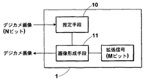
以下、本発明の画像処理装置の一実施の形態について図面を用いて説明する。図1は、本実施の形態の構成を表すブロック図である。
【0019】
画像処理装置1は、デジタル画像の各画素をNビットで表した原信号の値の最下位桁にnビット増やすことによりM(M=N+n)ビットに拡張してビット分解能を向上させた拡張信号に変換するために、各画素の原信号の値とその画素の近傍数画素の画素値の平均値との差によって定まる補正値をこの原信号に加えて各画素の原信号の値の精度を上げた推定信号を求める推定手段10と、この推定信号の値を2n倍した後、下位桁を丸めて上位桁Mビットの拡張信号に変換してデジタル画像を形成する画像形成手段11とを備えたものである。
【0020】
まず、推定手段10は、デジタル画像の原信号からデジタル化(量子化)前の原画像から得られた信号の推定を行う。
【0021】
デジタル画像の各画素が持つ画素値は、原画像から得られた信号を量子化したものであり、図2に示すように、ある程度幅(幅d)を持った信号が1つの階調に変換され、2つの階調の間にある信号はいずれか近い方の階調に量子化される。分解能を上げると1つの階調に対応する信号の幅は狭くなり、分解能の低い階調で表された1つの画素値は、分解能を上げると複数の画素値に対応することになる。例えば、256階調(N=8ビット)の画像データを1024階調(M=10ビット)に上げると、256階調で「10」と表された画素値は、1024階調では「39」、「40」、「41」、「42」の4つの画素値のいずれかに対応する。つまり、256階調で「10」と表された画素は、デジタル化前の原画像から得られた信号を直接1024階調で量子化した場合には「39」、「40」、「41」、「42」の4つのいずれかの画素値に変換される。
【0022】
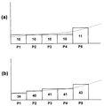
そこで、例えば、図3の破線に示すように画像の色/濃度(画像の信号)が緩やかに変化している部分を分解能の低い階調で量子化すると、P1〜P4までの画素値は同じ値となり画素P5でわずかに画素値が変わるようになる場合がある。このような同じ値を持つ画素(P1〜P4)が並んでいる部分もビット分解能が高い階調で量子化すると、画素P5に向かって徐々に変化するような画素値を持つことになる場合が多い。例えば、図3(a)ではP1〜P4までの画素値は「10」、画素P5では「11」となっているが、図3(b)に示すように、分解能を上げるとP1〜P5の画素値は「39」、「40」、「41」、「41」、「43」と順次変化する。
【0023】
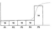
一方、図4に示すように、画素P4と画素P5で画素値が急に変わる場合もある。このような場合には、原画像から得られる信号も破線で示すように急に変わる輪郭のようなエッジである可能性が高い。このように画素値が急に変化するところであっても、前述のように緩やかに画素値が変化するところであっても、原画像が持っていた信号はこの画素値に量子化された所定の範囲内(例えば、図2(a)の幅dの範囲内)の値しか取り得ない。例えば量子化した画素値が「10」の場合、原画像から得られた信号の値forgは、9.5≦forg<10.5の間にあったものを量子化したものである。つまり、量子化した画素値「10」には、このような量子化誤差を含んでいるものといえる。
【0024】
以上のことを考慮すると、デジタル画像の画素値から原画像が持っていた信号を推定する場合には、各画素を近傍の画素の画素値に向かって徐々に変化させたものであって、且つ量子化前に原画像がとり得る範囲内(量子化誤差の範囲内)の信号としたものが適当であると考えられる。
【0025】
そこで、原画像が持っていたと推定される推定信号は、デジタル画像の各画素の原信号を近傍画素の画素値に近づけるように精度を上げたものとし、推定信号の下位桁を丸めると原信号の値に戻るように決めたものが最も適当な値であるといえる。
【0026】
例えば、原信号が8ビットで表されていた場合について具体的に考える。まず、8ビットの整数値で表されていた原信号の値を、例えば浮動小数点などの桁数の多い数値に変換し、所定の画素の原信号の値forgとこの画素の近傍K個の画素の画素値fiの平均値favr=Σfi/Kと原信号の値forgの差を原信号に加えて各画素の原信号の値の精度を上げた推定信号を求める。しかし、近傍画素に画素値が急に変化するような画素がある場合(画素値が急に大きくなる画素や急に小さくなるような画素が近傍にある場合)には、平均値との差を原信号にそのまま加えてもその近傍画素の値に影響され量子化誤差の範囲を越えた値となる。
【0027】
そこで、
推定信号=forg+T(favr−forg) (1)
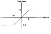
T:近傍数画素の画素値の平均値との差によって定まる関数
(例えば、図5に示す関数)
とし、推定信号が量子化誤差の範囲内の値となるように、原信号に0.5>T(favr−forg)>−0.5の範囲の補正値を加えるようにする。つまり、推定信号を四捨五入すると原信号の値と一致するように推定信号を決める。
【0028】
具体的に説明すると、図6(a)に示すように画素値が並んでいる画像に対してマスク5の平均値と原信号との差を原信号に加えると、図6(b)に示すような推定信号になる。一方、図7(a)に示すように、矢印のところで画素値が急に変化するようなところがある場合に、単純にマスク5の平均値と原信号との差を原信号に加えると、図7(b)に示すような推定信号になり矢印の周辺の画素では周囲の画素値に影響されて四捨五入しても原信号に戻らない値となる。そこで、式(1)を適応すれば図7(c)に示すような推定信号となり、小数点以下を四捨五入すると原信号に戻るように推定信号を求めることができる。
【0029】
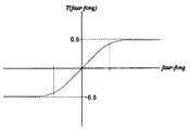
式(1)で示した関数Tは、図8に示すようなシグモイド関数のようなものでもよく、小数点以下を四捨五入すると原信号に戻るように定まる関数であればよい。
【0030】
画像形成手段11では、推定手段10で求めた推定信号から原信号の分解能をnビットほど増したMビットの拡張信号に変換し、この拡張信号を用いてデジタル画像の形成を行う。
【0031】
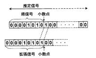
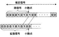
推定手段10で求めた推定信号は、補正値を原信号に加えることにより原信号の元のデジタル画像Nビット以上の精度を持つ桁数の多い値となっている。そこで、例えば、8(N)ビットの原信号に1(n)ビット増した9(M)ビットの拡張信号にする場合には、図9に示すように推定信号を2倍(=21倍)にして少数点以下を四捨五入すれば9ビットの拡張信号に変換することができる。例えば、図6(b)に示すような推定信号を2倍にして四捨五入すれば図6(c)のような拡張信号を得られる。同様に、8ビットの原信号を2ビット増した10ビットの拡張信号にするためには、図10に示すように推定信号を4倍(=22倍)にして、少数点以下を四捨五入すれば10ビットの拡張信号に変換することができる。
【0032】
次に、本画像処理装置1の作用について説明する。ここでは、ルックアップテーブルを用いて256階調から256階調の階調変換を行う場合について説明する。
【0033】
まず、256階調で表されたデジタル画像の各画素に対して、推定手段10で原信号に近傍画素の画素値の平均値との差によって定まる補正値を加えて各画素の原信号の精度を上げた推定信号を求める。
【0034】
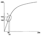
そこで、画像形成手段11で、例えば推定信号をもとに10ビットの拡張信号に変換し、1024階調にした後に図11に示すようなルックアップテーブルを適用して1024階調から256階調に階調変換する。図11の拡張信号に変換した場合と図12の拡張信号に変換しなかった場合を比較すると、図12のLの部分では1つの階調に対して3階調違うが、図11のLの部分では4つの階調に対して3階調が対応する。このように、元となる信号が1024階調の拡張信号に変換されて分解能が上がっているため、Lの部分のように急に階調が変化するようなところにおいてもトーンジャンプが発生する確率が少なくなる。
【0035】
また、このような処理を施した場合でも、推定値は量子化誤差の範囲内で推定されるので、輪郭のように急激に画素値が変化するようなところで周囲の画素の値に影響されて画像がぼけることはない。
【0036】
以上、1方向の列に画素が並んでいる場合を例に説明したが、平面上で2次元に画素が並んでいる場合についても同様に行うことが可能である。
【0037】
また、上述では四捨五入して丸める場合について説明したが、切り上げ、切り下げ、二捨三入など他の方法を用いて丸めたときに量子化誤差の範囲内になるように算出されるものとしてもよい。
【図面の簡単な説明】
【図1】画像処理装置の構成を表すブロック図
【図2】分解能の違いによる量子化される階調を説明するための図
【図3】分解能の違いによる階調の変化を説明するための図
【図4】階調の変化と元の画像から得られた信号値との関係を説明するための図
【図5】推定信号を求めるための関数を表す図(その1)
【図6】推定信号と拡張信号を説明するための図(その1)
【図7】推定信号と拡張信号を説明するための図(その2)
【図8】推定信号を求めるための関数を表す図(その2)
【図9】ビット分解能を1ビット上げた拡張信号を求める方法を説明するための図
【図10】ビット分解能を2ビット上げた拡張信号を求める方法を説明するための図
【図11】拡張信号を用いて1024階調から256階調に階調変換するルックアップテーブルの図
【図12】256階調から256階調に階調変換するルックアップテーブルの図
【符号の説明】
1 画像処理装置
10 推定手段
11 画像形成手段[0001]
BACKGROUND OF THE INVENTION
The present invention relates to an image processing method and apparatus for preventing the occurrence of tone jump in gradation processing of a digital image signal.
[0002]
[Prior art]
Conventionally, when reproducing a digital image such as an image obtained by photographing with a digital camera or a medical image obtained by photographing with CR or MRI, characteristic variation correction processing by CCD, density conversion, gradation processing The image is processed so that the image of interest can be easily seen.
[0003]
Of such image processing, in gradation processing, gradation conversion is performed using a look-up table having conversion characteristics from the horizontal axis to the vertical axis as shown in FIG. There is a problem that a tone jump is likely to occur at a portion such as a changing portion L. In particular, when the resolution of the original image on which gradation processing is performed is not sufficient (for example, conversion from 256 gradations to 256 gradations), pixel values that differ by only one gradation in the original image are converted to the third floor after gradation processing. Since the pixel values are different (part L), a point where the color / density suddenly changes appears in the gradation area which should have changed gradually, and the change becomes noticeable. Thereby, it may appear that there is a contour where there is no contour (referred to as a false contour).
[0004]
Therefore, as a method of reducing the tone jump and false contour generated by increasing the resolution of the digital signal, a random number signal generated by using a random number generation circuit in the least significant digit part (for example, the last two digits) of the digital image signal The effect similar to the case where random numbers are added by using noise on particles of photographic film for data added to the least significant digit part (for example, Patent Document 1) There is something that can be obtained. (For example, Patent Document 2)
Alternatively, a method of reducing tone jumps and false contours by adding up the surrounding pixel values to increase the number of apparent effective bits has been used.
[0005]
[Patent Document 1]
JP-A-6-203148 [0006]
[Patent Document 2]
Japanese Patent Laid-Open No. 10-13673
[Problems to be solved by the invention]
As described above, with the method of adding bits using random numbers or the like, it was possible to make the step due to tone jump difficult to see by blurring uniformly, but the relationship with surrounding pixels was considered. Therefore, even if the resolution is increased in a gradation area where the gradation gradually changes, the gradation cannot be changed along with the change.
[0008]
On the other hand, in the method of increasing the apparent number of effective bits by adding up the surrounding pixel values, it is possible to change the gradation according to the change where the gradation gradually changes. , Where the entire image is blurred so as to approach the surrounding pixel values, and the pixel values of the original original image change abruptly (for example, where there are edges such as contours) There was a problem that the image was blurred by being influenced by.
[0009]
In view of this problem, an object of the present invention is to provide an image processing apparatus that can suppress the occurrence of tone jump and does not blur an image more than necessary.
[0010]
[Means for Solving the Problems]
In the image processing method of the present invention, the number of signal bits is expanded to M (M = N + n) bits by increasing n bits to the least significant digit of the value of the original signal in which each pixel of the digital image is represented by N bits. In an image processing method for converting into an extended signal with improved resolution,
An estimated signal obtained by adding a correction value determined by the difference between the value of the original signal of the pixel and the average value of the pixel values of the neighboring pixels of the pixel to the original signal to increase the accuracy of the value of the original signal of each pixel. Seeking steps,
After rounding the value of the estimated signal by 2 n , rounding the lower digits and converting them to the extended signal of the upper digits M bits to form a digital image,
The correction value is determined to be a value that returns to the value of the original signal when the lower digit of the estimated signal is rounded.
[0011]
The image processing apparatus of the present invention extends the number of signal bits to M (M = N + n) bits by increasing n bits to the least significant digit of the value of the original signal in which each pixel of the digital image is represented by N bits. In an image processing device that converts an extended signal with improved bit resolution,
An estimated signal obtained by adding a correction value determined by the difference between the value of the original signal of the pixel and the average value of the pixel values of the neighboring pixels of the pixel to the original signal to increase the accuracy of the value of the original signal of each pixel. An estimation means to be obtained;
Image forming means for multiplying the value of the estimated signal by 2 n , rounding the lower digit and converting it to the extended signal of the upper digit M bits to form a digital image;
The correction value is determined to be a value that returns to the value of the original signal when the lower digit of the estimated signal is rounded.
[0012]
The program of the present invention extends the number of signal bits to M (M = N + n) bits by increasing n bits to the least significant digit of the value of the original signal in which each pixel of the digital image is represented by N bits. In a program for causing a computer to execute image processing for conversion into an extended signal with improved resolution,
An estimated signal obtained by adding a correction value determined by the difference between the value of the original signal of the pixel and the average value of the pixel values of the neighboring pixels of the pixel to the original signal to increase the accuracy of the value of the original signal of each pixel. Seeking steps,
A program for executing a step of rounding a lower digit and converting the value of the estimated signal to 2 n times to convert it into the extended signal of upper digits M bits to form a digital image,
The correction value is determined to be a value that returns to the value of the original signal when the lower digit of the estimated signal is rounded.
[0013]
“To increase the bit resolution by increasing n bits to the least significant digit of the value of the original signal that represents the pixel in N bits to improve the bit resolution” means that the pixel value of each pixel is By adding the bit of the least significant digit of the bits to be represented, the resolution is improved so that the quantized one pixel value can be represented by a plurality of pixel values in the original gradation. For example, when the pixel value of the image data is expressed by 256 gradations, 8 (N) bits are required. However, when the resolution is increased and the pixel value is expressed by 1024 gradations, 10 (M) bits are required. . Therefore, by increasing 2 (n) bits to 10 bits to the least significant digit of the pixel value represented by 8 bits, the original 8 bits can be divided into four parts that are represented by one pixel value. Expressed in pixel value.
[0014]
In addition, the “estimated signal in which the accuracy of the value of the original signal is increased” specifically means that the gradation of the original signal is represented by an 8-bit integer, for example, a floating point and the number of significant digits is 8 It is a signal represented by a numerical value that is greater than or equal to a bit. As long as the number of significant digits is 8 bits or more, it may be converted to an integer having a large number of digits even if it is not a floating point.
[0015]
Also, “determine a value that returns to the value of the original signal when the lower digit of the estimated signal is rounded” is to match the original signal by rounding the lower digit of the estimated signal with higher accuracy by rounding off. The estimation signal is determined, which means that the estimation signal is determined so as to fall within the quantization error range when the original signal is quantized.
[0016]
“After multiplying the value of the estimated signal by 2n , the lower digit is rounded and converted into an extended signal of M bits of the upper digit”, specifically, for example, the estimated signal calculated in floating point with higher accuracy is 8 bits. When converting to a 10-bit gradation increased by 2 (= n) bits from the gradation, the estimated signal is multiplied by 4 (= 2 2 ) and the lower-order digits after the decimal point are rounded. The value of the signal representing the gray level of this is used as an extended signal.
[0017]
【The invention's effect】
According to the image processing of the present invention, in order to increase the bit to the least significant digit of the value of the original signal of each pixel of the digital image and improve the bit resolution, the correction value determined by the original signal of the pixel and the neighboring pixels of this pixel In addition to the original signal, a signal value with an increased bit resolution is obtained on the basis of an estimated signal with increased accuracy, so that tone jumps can be suppressed by blurring so as to approach the surrounding pixel values. Furthermore, since the estimated signal with higher accuracy is determined so that the lower digit is rounded, it returns to the original signal value. Therefore, when the pixel value changes suddenly where there is a contour, the original signal is quantized. Since the estimation signal is determined so as not to exceed the error, it is possible to prevent the image from being blurred more than necessary due to the influence of surrounding pixel values.
[0018]
DETAILED DESCRIPTION OF THE INVENTION
Hereinafter, an embodiment of an image processing apparatus of the present invention will be described with reference to the drawings. FIG. 1 is a block diagram showing the configuration of the present embodiment.
[0019]
The
[0020]
First, the estimation means 10 estimates a signal obtained from an original image before digitization (quantization) from the original signal of the digital image.
[0021]
The pixel value of each pixel of the digital image is a quantized signal obtained from the original image. As shown in FIG. 2, a signal having a certain width (width d) is converted into one gradation. Then, the signal between the two gradations is quantized to the closest gradation. When the resolution is increased, the width of a signal corresponding to one gradation is narrowed, and one pixel value represented by a gradation having a low resolution corresponds to a plurality of pixel values when the resolution is increased. For example, when image data of 256 gradations (N = 8 bits) is increased to 1024 gradations (M = 10 bits), the pixel value represented as “10” in 256 gradations is “39” in 1024 gradations. , “40”, “41”, and “42”. That is, the pixel represented as “10” in 256 gradations is “39”, “40”, “41” when the signal obtained from the original image before digitization is directly quantized in 1024 gradations. , “42” is converted into one of the four pixel values.
[0022]
Therefore, for example, when a portion where the color / density (image signal) of the image changes slowly as shown by the broken line in FIG. 3 with a gradation with low resolution, the pixel values from P1 to P4 are the same. The pixel value may slightly change in the pixel P5. If such a portion where pixels (P1 to P4) having the same value are arranged is quantized with a gradation having a high bit resolution, the pixel value may gradually change toward the pixel P5. Many. For example, in FIG. 3A, the pixel values from P1 to P4 are “10” and the pixel P5 is “11”. However, as shown in FIG. The pixel value sequentially changes as “39”, “40”, “41”, “41”, “43”.
[0023]
On the other hand, as shown in FIG. 4, the pixel value may change suddenly between the pixel P4 and the pixel P5. In such a case, the signal obtained from the original image is also likely to be a contour-like edge that suddenly changes as indicated by a broken line. In this way, whether the pixel value changes suddenly or where the pixel value changes slowly as described above, the signal held in the original image is a predetermined range quantized to this pixel value. Only a value within (for example, within the range of the width d in FIG. 2A) can be taken. For example, when the quantized pixel value is “10”, the value forg of the signal obtained from the original image is a quantized value between 9.5 ≦ forg <10.5. That is, it can be said that the quantized pixel value “10” includes such a quantization error.
[0024]
Considering the above, when estimating the signal that the original image had from the pixel value of the digital image, each pixel is gradually changed toward the pixel value of the neighboring pixels, and A signal that is within the range that can be taken by the original image before quantization (within the range of quantization error) is considered appropriate.
[0025]
Therefore, the estimated signal estimated to have been in the original image is assumed to have increased accuracy so that the original signal of each pixel of the digital image is brought closer to the pixel value of the neighboring pixel. It can be said that the most appropriate value is determined to return to the value of.
[0026]
For example, consider a case where the original signal is represented by 8 bits. First, the value of the original signal represented by an 8-bit integer value is converted into a numerical value with a large number of digits such as a floating point, for example, and the original signal value forg of a predetermined pixel and K pixels in the vicinity of this pixel The difference between the average value favr = Σfi / K of the original pixel value fi and the original signal value forg is added to the original signal to obtain an estimated signal with increased accuracy of the original signal value of each pixel. However, if there is a pixel whose pixel value changes suddenly in the neighboring pixels (a pixel whose pixel value suddenly increases or a pixel whose pixel value suddenly decreases), the difference from the average value is calculated. Even if it is added to the original signal as it is, it is affected by the value of its neighboring pixels, and becomes a value exceeding the range of quantization error.
[0027]
Therefore,
Estimated signal = forg + T (favr−forg) (1)
T: a function determined by the difference from the average value of the pixel values of several neighboring pixels (for example, the function shown in FIG. 5)
And a correction value in the range of 0.5> T (favr-forg)> − 0.5 is added to the original signal so that the estimated signal becomes a value within the quantization error range. That is, when the estimated signal is rounded off, the estimated signal is determined so as to match the value of the original signal.
[0028]
More specifically, when the difference between the average value of the mask 5 and the original signal is added to the original signal for an image in which pixel values are arranged as shown in FIG. 6A, the original signal is shown in FIG. 6B. The estimated signal is as follows. On the other hand, as shown in FIG. 7A, when there is a place where the pixel value suddenly changes at the arrow, if the difference between the average value of the mask 5 and the original signal is simply added to the original signal, The estimated signal is as shown in FIG. 7B, and the pixels around the arrow are affected by the surrounding pixel values and do not return to the original signal even if rounded off. Therefore, by applying the formula (1), an estimated signal as shown in FIG. 7C is obtained, and the estimated signal can be obtained so as to return to the original signal when the decimal part is rounded off.
[0029]
The function T shown in the equation (1) may be a sigmoid function as shown in FIG. 8, or any function that can be determined so as to return to the original signal by rounding off after the decimal point.
[0030]
The
[0031]
The estimated signal obtained by the estimating means 10 is a value with a large number of digits having an accuracy of N bits or more of the original digital image of the original signal by adding a correction value to the original signal. Therefore, for example, when an 9 (M) -bit extended signal increased by 1 (n) bits to an 8 (N) -bit original signal, the estimated signal is doubled (= 2 1 times) as shown in FIG. ) And rounding off the decimal point, it can be converted into a 9-bit extended signal. For example, if the estimated signal as shown in FIG. 6B is doubled and rounded off, an extended signal as shown in FIG. 6C can be obtained. Similarly, to a 10-bit extension signals with increased 2-bit original signals of 8 bits, then four times the estimated signal as shown in FIG. 10 (= 2 2 times), by rounding off the decimal point For example, it can be converted into a 10-bit extension signal.
[0032]
Next, the operation of the
[0033]
First, for each pixel of a digital image expressed in 256 gradations, the estimation means 10 adds a correction value determined by the difference from the average value of the pixel values of neighboring pixels to the original signal, and the accuracy of the original signal of each pixel Obtain an estimated signal with
[0034]
Therefore, the image forming means 11 converts, for example, an estimated signal into a 10-bit extension signal and converts it to 1024 gradations, and then applies a lookup table as shown in FIG. Tone conversion. Comparing the case of converting to the extension signal of FIG. 11 and the case of not converting to the extension signal of FIG. 12, the portion L in FIG. In the portion, three gradations correspond to four gradations. Thus, since the original signal is converted into an extended signal of 1024 gradations and the resolution is increased, the probability that a tone jump occurs even in a place where the gradation changes suddenly as in the L portion. Less.
[0035]
Even when such processing is performed, the estimated value is estimated within the range of the quantization error, so it is influenced by the values of surrounding pixels where the pixel value changes abruptly as in the contour. The image is never blurred.
[0036]
As described above, the case where the pixels are arranged in a column in one direction has been described as an example. However, the case where the pixels are arranged two-dimensionally on a plane can be similarly performed.
[0037]
In the above description, rounding is performed by rounding, but it may be calculated so as to be within the quantization error range when rounded using other methods such as rounding up, rounding down, rounding off, etc. .
[Brief description of the drawings]
FIG. 1 is a block diagram showing a configuration of an image processing apparatus. FIG. 2 is a diagram for explaining gradations to be quantized due to a difference in resolution. FIG. 3 is a diagram for explaining changes in gradations due to a difference in resolution. FIG. 4 is a diagram for explaining a relationship between a change in gradation and a signal value obtained from an original image. FIG. 5 is a diagram showing a function for obtaining an estimated signal (part 1).
FIG. 6 is a diagram for explaining an estimated signal and an extended signal (part 1);
FIG. 7 is a diagram for explaining an estimated signal and an extended signal (part 2);
FIG. 8 is a diagram illustrating a function for obtaining an estimated signal (part 2);
FIG. 9 is a diagram for explaining a method for obtaining an extended signal with a bit resolution increased by 1 bit. FIG. 10 is a diagram for explaining a method for obtaining an extended signal with a bit resolution increased by 2 bits. FIG. 12 is a diagram of a lookup table for gradation conversion from 1024 gradations to 256 gradations using FIG. 12. FIG. 12 is a diagram of a lookup table for gradation conversion from 256 gradations to 256 gradations.
DESCRIPTION OF
Claims (3)
該画素の原信号の値と該画素の近傍数画素の画素値の平均値との差によって定まる補正値を該原信号に加えて前記各画素の原信号の値の精度を上げた推定信号を求めるステップと、
該推定信号の値を2n倍した後、下位桁を丸めて上位桁Mビットの前記拡張信号に変換してデジタル画像を形成するステップとを備え、
前記補正値が、前記推定信号の下位桁を丸めたとき原信号の値に戻るような値に決められていることを特徴とする画像処理方法。An extended signal in which the number of signal bits is increased to M (M = N + n) bits to increase the bit resolution by increasing n bits to the least significant digit of the value of the original signal representing each pixel of the digital image in N bits. In the image processing method for conversion,
An estimated signal obtained by adding a correction value determined by the difference between the value of the original signal of the pixel and the average value of the pixel values of the neighboring pixels of the pixel to the original signal to increase the accuracy of the value of the original signal of each pixel. Seeking steps,
After rounding the value of the estimated signal by 2 n , rounding the lower digits and converting them to the extended signal of the upper digits M bits to form a digital image,
The image processing method, wherein the correction value is determined to be a value that returns to the value of the original signal when the lower digit of the estimated signal is rounded.
該画素の原信号の値と該画素の近傍数画素の画素値の平均値との差によって定まる補正値を該原信号に加えて前記各画素の原信号の値の精度を上げた推定信号を求める推定手段と、
該推定信号の値を2n倍した後、下位桁を丸めて上位桁Mビットの前記拡張信号に変換してデジタル画像を形成する画像形成手段とを備え、
前記補正値が、前記推定信号の下位桁を丸めたとき原信号の値に戻るような値に決められていることを特徴とする画像処理装置。An extended signal in which the number of signal bits is increased to M (M = N + n) bits to increase the bit resolution by increasing n bits to the least significant digit of the value of the original signal representing each pixel of the digital image in N bits. In the image processing device for conversion,
An estimated signal obtained by adding a correction value determined by the difference between the value of the original signal of the pixel and the average value of the pixel values of the neighboring pixels of the pixel to the original signal to increase the accuracy of the value of the original signal of each pixel. An estimation means to be obtained;
Image forming means for multiplying the value of the estimated signal by 2 n , rounding the lower digit and converting it to the extended signal of the upper digit M bits to form a digital image;
The image processing apparatus according to claim 1, wherein the correction value is determined to be a value that returns to a value of an original signal when a lower digit of the estimated signal is rounded.
該画素の原信号の値と該画素の近傍数画素の画素値の平均値との差によって定まる補正値を該原信号に加えて前記各画素の原信号の値の精度を上げた推定信号を求めるステップと、
該推定信号の値を2n倍した後、下位桁を丸めて上位桁Mビットの前記拡張信号に変換してデジタル画像を形成するステップとを実行させるためのプログラムであって、
前記補正値が、前記推定信号の下位桁を丸めたとき原信号の値に戻るような値に決められていることを特徴とするプログラム。An extended signal in which the number of signal bits is increased to M (M = N + n) bits to increase the bit resolution by increasing n bits to the least significant digit of the value of the original signal representing each pixel of the digital image in N bits. In a program for causing a computer to execute image processing to be converted,
An estimated signal obtained by adding a correction value determined by the difference between the value of the original signal of the pixel and the average value of the pixel values of the neighboring pixels of the pixel to the original signal to increase the accuracy of the value of the original signal of each pixel. Seeking steps,
A program for executing a step of rounding a lower digit and converting the value of the estimated signal to 2 n times to convert it into the extended signal of upper digits M bits to form a digital image,
The program is characterized in that the correction value is determined to be a value that returns to the value of the original signal when the lower digit of the estimated signal is rounded.
Priority Applications (1)
| Application Number | Priority Date | Filing Date | Title |
|---|---|---|---|
| JP2003203461A JP2005051337A (en) | 2003-07-30 | 2003-07-30 | Image processing method, image processing apparatus, and program |
Applications Claiming Priority (1)
| Application Number | Priority Date | Filing Date | Title |
|---|---|---|---|
| JP2003203461A JP2005051337A (en) | 2003-07-30 | 2003-07-30 | Image processing method, image processing apparatus, and program |
Publications (1)
| Publication Number | Publication Date |
|---|---|
| JP2005051337A true JP2005051337A (en) | 2005-02-24 |
Family
ID=34262805
Family Applications (1)
| Application Number | Title | Priority Date | Filing Date |
|---|---|---|---|
| JP2003203461A Withdrawn JP2005051337A (en) | 2003-07-30 | 2003-07-30 | Image processing method, image processing apparatus, and program |
Country Status (1)
| Country | Link |
|---|---|
| JP (1) | JP2005051337A (en) |
Cited By (4)
| Publication number | Priority date | Publication date | Assignee | Title |
|---|---|---|---|---|
| JP2009100472A (en) * | 2007-10-15 | 2009-05-07 | Intel Corp | Bit depth enhancement for scalable video coding |
| US7649652B2 (en) | 2005-10-10 | 2010-01-19 | Samsung Electronics Co., Ltd. | Method and apparatus for expanding bit resolution using local information of image |
| US8204333B2 (en) | 2007-10-15 | 2012-06-19 | Intel Corporation | Converting video and image signal bit depths |
| US9171358B2 (en) | 2012-09-26 | 2015-10-27 | Olympus Corporation | Image editing device and image editing method |
-
2003
- 2003-07-30 JP JP2003203461A patent/JP2005051337A/en not_active Withdrawn
Cited By (6)
| Publication number | Priority date | Publication date | Assignee | Title |
|---|---|---|---|---|
| US7649652B2 (en) | 2005-10-10 | 2010-01-19 | Samsung Electronics Co., Ltd. | Method and apparatus for expanding bit resolution using local information of image |
| JP2009100472A (en) * | 2007-10-15 | 2009-05-07 | Intel Corp | Bit depth enhancement for scalable video coding |
| US8204333B2 (en) | 2007-10-15 | 2012-06-19 | Intel Corporation | Converting video and image signal bit depths |
| US8208560B2 (en) | 2007-10-15 | 2012-06-26 | Intel Corporation | Bit depth enhancement for scalable video coding |
| DE102008051486B4 (en) * | 2007-10-15 | 2017-04-13 | Intel Corporation | Convert video and video bit depths |
| US9171358B2 (en) | 2012-09-26 | 2015-10-27 | Olympus Corporation | Image editing device and image editing method |
Similar Documents
| Publication | Publication Date | Title |
|---|---|---|
| JP4217657B2 (en) | Image processing method, program, storage medium, and apparatus | |
| US8917419B2 (en) | Image processing apparatus and control method thereof | |
| JP4874184B2 (en) | Image processing apparatus and image processing method | |
| KR20070078463A (en) | Apparatus and method for reducing noise from image sensor | |
| JP2006065834A (en) | Image processing device and image processing method | |
| JP2011114413A (en) | Image processing unit and method of processing image | |
| JP2002077623A (en) | Image processing apparatus | |
| JP2005051337A (en) | Image processing method, image processing apparatus, and program | |
| EP0786741B1 (en) | Method and apparatus for binary coding of image data | |
| JP5024112B2 (en) | Image signal processing apparatus and image signal processing program | |
| JP5103580B2 (en) | Image processing apparatus and digital camera | |
| JP3771145B2 (en) | Image processing method, image processing apparatus, and image forming apparatus | |
| JP3813361B2 (en) | Image processing apparatus and image processing method | |
| JP4342297B2 (en) | Image processing circuit and image processing method | |
| JPH05183737A (en) | Picture processor | |
| JP3124589B2 (en) | Image processing device | |
| JP4086669B2 (en) | Image processing method and apparatus | |
| JP2860039B2 (en) | Pseudo halftone image reduction device | |
| JP2898322B2 (en) | Halftone estimation method for dither image | |
| JP2006191457A (en) | Image processor, image-processing method, program for allowing computer to execute the method, image-forming apparatus, and computer-readable recording medium with the program recorded thereon | |
| JP3560265B2 (en) | Pseudo halftone processing method | |
| JP2004282746A (en) | Image data processor and image data processing method | |
| JP2024015724A (en) | Image processing device and program | |
| JPH09107472A (en) | Method and device for image data conversion | |
| JP3714820B2 (en) | Image processing method |
Legal Events
| Date | Code | Title | Description |
|---|---|---|---|
| A300 | Application deemed to be withdrawn because no request for examination was validly filed |
Free format text: JAPANESE INTERMEDIATE CODE: A300 Effective date: 20061003 |