JP2005050317A - Rendering successive flames in graphic object system - Google Patents
Rendering successive flames in graphic object system Download PDFInfo
- Publication number
- JP2005050317A JP2005050317A JP2004190407A JP2004190407A JP2005050317A JP 2005050317 A JP2005050317 A JP 2005050317A JP 2004190407 A JP2004190407 A JP 2004190407A JP 2004190407 A JP2004190407 A JP 2004190407A JP 2005050317 A JP2005050317 A JP 2005050317A
- Authority
- JP
- Japan
- Prior art keywords
- edge
- frame
- level
- edges
- pixel
- Prior art date
- Legal status (The legal status is an assumption and is not a legal conclusion. Google has not performed a legal analysis and makes no representation as to the accuracy of the status listed.)
- Pending
Links
Images


Classifications
-
- G—PHYSICS
- G06—COMPUTING; CALCULATING OR COUNTING
- G06T—IMAGE DATA PROCESSING OR GENERATION, IN GENERAL
- G06T11/00—2D [Two Dimensional] image generation
- G06T11/40—Filling a planar surface by adding surface attributes, e.g. colour or texture
-
- G—PHYSICS
- G06—COMPUTING; CALCULATING OR COUNTING
- G06T—IMAGE DATA PROCESSING OR GENERATION, IN GENERAL
- G06T13/00—Animation
- G06T13/80—2D [Two Dimensional] animation, e.g. using sprites
Abstract
Description
本発明は、一般的に、グラフィカルオブジェクトデータのレンダリングに関し、特に、一連のフレームを動画化することを目的とした効率的なレンダリングに関する。 The present invention relates generally to rendering graphical object data, and more particularly to efficient rendering for the purpose of animating a series of frames.
レンダリングシステムは、出力装置上又はフレームバッファ内での表示に必要なものの記述を入力として受け取る。通常、このような記述は、基本的なグラフィカルオブジェクトの輪郭又は各部分を記述する稜線又はベクトルデータの集合を含むことが多い。例えば、フォントグリフはこのように記述することができるだろう。記述は、レンダリングシステムに出力装置又はフレームバッファ中の出力画素に対して色を選択する方法を通知する塗りつぶし情報を含んでも良い。この塗りつぶし情報は、一般的に、稜線又はベクトルデータの1つ以上の集合と関連付けられる。例えば、赤色は稜線又はベクトルデータの集合と関連付けられ、赤色フォントグリフを生成することができるだろう。ベクトル又は稜線ベースのグラフィックデータの入力集合をとり、出力として画素値を生成するプロセスは従来技術では走査変換として知られている。 The rendering system receives as input a description of what is needed for display on the output device or in the frame buffer. Typically, such a description often includes a set of edge or vector data describing the outline or portions of a basic graphical object. For example, a font glyph could be written like this: The description may include fill information that informs the rendering system how to select a color for the output device or output pixels in the frame buffer. This fill information is typically associated with one or more sets of edge lines or vector data. For example, red could be associated with a ridgeline or collection of vector data to generate a red font glyph. The process of taking an input set of vector or edge-based graphic data and generating pixel values as output is known in the prior art as scan conversion.
走査変換の1つの方法は、各稜線の最小y座標に基づいて各グラフィカルオブジェクトの稜線をバケットへとソートすることを伴う。出力画像は、稜線の対応するバケットを使用して、一度に1本の走査線で生成される。このプロセス中、画像を後続の走査線まで継続する稜線を含むアクティブ稜線リストが維持される。このプロセスは、計算上費用がかかる可能性がある−これは、特に、アクティブ稜線リストのソーティングがパイプラインシステムの一部として容易に実現できないためである。 One method of scan conversion involves sorting the edges of each graphical object into buckets based on the minimum y coordinate of each edge. The output image is generated one scan line at a time using the corresponding bucket of ridge lines. During this process, an active edge list is maintained that includes edges that continue the image to subsequent scan lines. This process can be computationally expensive—particularly because the sorting of the active edge list cannot be easily implemented as part of a pipeline system.
メモリを節約するために、従来のレンダリングシステムは、入力グラフィカルオブジェクトが変換行列と共に入力として提供されるようにする。これにより、メモリ中のオブジェクトの単一の定義は、種々の位置、向き、曲がり、又は種々の換算係数を伴って出力画素の一部を形成するのに使用することができる。このようなレンダリングシステムの最初のステップのうちの1つは、通常、入力グラフィカルオブジェクトデータの各座標への変換行列の適用であるだろう。このステップはソーティングステップの前に行なわれなければならない。ストローキング、モーフィング、及びシザリングなどのソーティングステップの前に行なわれなければならない従来技術において周知のプロセスが更に存在する(出力に影響しない稜線/稜線の一部の削除)。 In order to save memory, conventional rendering systems allow input graphical objects to be provided as input along with a transformation matrix. Thus, a single definition of an object in memory can be used to form part of the output pixel with various positions, orientations, bends, or various conversion factors. One of the first steps of such a rendering system will typically be the application of a transformation matrix to each coordinate of the input graphical object data. This step must be done before the sorting step. There are further processes known in the prior art that must be performed prior to sorting steps such as stroking, morphing, and scissoring (deleting edges / parts of edges that do not affect output).
上述のようなレンダリングシステムは、出力表示装置上で又は出力フレームバッファ内で動画画像を生成するのに使用することができる。入力は1度に1つのフレームで受け取ることができ、対応する出力は一度に1つのフレームで生成することができる。しかし、上述の従来のレンダリングシステムは、稜線は入力としてフレームごとに渡される必要があり、レンダリングシステムは同じ処理(例えば、変換、ストローキング、モーフィング、及びシザリング)をフレームごとに行なう必要があるので、この役割においては非効率的である。また、全ての入力稜線はフレームごとの再ソートを必要とするので、計算上費用がかかる可能性がある。 A rendering system as described above can be used to generate a moving image on an output display device or in an output frame buffer. Input can be received one frame at a time and the corresponding output can be generated one frame at a time. However, in the conventional rendering system described above, edges need to be passed for each frame as input, and the rendering system needs to perform the same processing (eg, transformation, stroking, morphing, and scissoring) for each frame. In this role is inefficient. In addition, all input edges need to be resorted for each frame, which may be computationally expensive.
本発明の目的は、既存の構成の1つ以上の欠点をほぼ克服、あるいは、少なくとも改善することである。 It is an object of the present invention to substantially overcome or at least ameliorate one or more disadvantages of existing configurations.
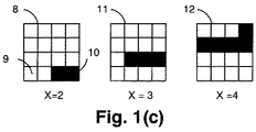
動画像列のうち1つのフレームと、その後のフレームとの時間的な一貫性を利用する従来のレンダリングシステムにおける問題点に対処するものである。特に、いくつかの隣接するフレームを通して「静」を維持したいくつかの稜線がしばしば登場する。この一例として、詳細な背景を有する画像を描画する際に用いられるエッジがある。 The present invention addresses a problem in a conventional rendering system that uses temporal consistency between one frame of a moving image sequence and a subsequent frame. In particular, there are often some ridgelines that remain "static" through several adjacent frames. One example of this is an edge used when drawing an image having a detailed background.
本発明の第1の態様によれば、フレームのシーケンスを動画化する目的でグラフィカルオブジェクトデータをレンダリングする方法であって、(a) グラフィカルオブジェクトの輪郭を記述する稜線データの入力集合を含む入力グラフィカルオブジェクトデータを受信する工程と、(b) 前記グラフィカルオブジェクトデータと関連付けられ且つ前記入力グラフィカルオブジェクトデータの表示方法を記述する入力パラメータを受信する工程と、(c) 前記入力パラメータを適用して処理稜線データの第1の集合を生成することによって前記稜線データの入力集合を処理する工程と、(d) 前記処理稜線データの第1の集合と先行フレームに対して生成された処理稜線データの第2の集合を使用して、現在のフレームに対して出力画像を生成する工程と、(e) 前記処理稜線データの第2の集合の部分集合を削除する工程と、(f) 前記処理稜線データの第1の集合の部分集合及び前記処理稜線データの第2の集合の部分集合を後続フレーム上で使用するために処理稜線データの第3の集合へと格納する工程とを備えることを特徴とするコンピュータを提供する。前記先行フレームに対する前記処理稜線データの第2の集合は、前記先行フレーム及び現在のフレームの双方において変更なしに表示されることが意図されるオブジェクトの稜線を備えることが好ましい。前記先行フレームの前記処理稜線の第3の集合は、前記現在のフレームに対する前記処理稜線の第2の集合として使用されるのが有利である。 According to a first aspect of the invention, a method for rendering graphical object data for the purpose of animating a sequence of frames, comprising: (a) an input graphical comprising an input set of edge data describing the contour of the graphical object; Receiving object data; (b) receiving input parameters associated with the graphical object data and describing a display method of the input graphical object data; and (c) processing edges by applying the input parameters. Processing the input set of ridge line data by generating a first set of data; (d) a second set of processed ridge line data generated for the first set of processed ridge line data and a preceding frame; Output image for the current frame using a set of (E) deleting a subset of the second set of the processing ridge line data; and (f) a subset of the first set of the processing ridge line data and a second set of the processing ridge line data. Storing a subset of the set into a third set of processing edge data for use on subsequent frames. The second set of processing edge data for the preceding frame preferably comprises an object edge that is intended to be displayed unchanged in both the preceding frame and the current frame. Advantageously, the third set of processing edges of the preceding frame is used as the second set of processing edges for the current frame.
本発明の別の面によると、画像フレームのシーケンスをレンダリングするようにグラフィックオブジェクト稜線データを処理する方法であって、
現在の画像フレームに対して、
(a) 前記現在の画像において開始する又は先行フレームから位置を変更した新規の稜線の順序付けられた集合と、前記先行画像フレームから持続し且つ前記先行フレームから位置を変更していない静止稜線の順序付けられた集合とに前記現在のフレームの画像に貢献する稜線をソートする工程と、
(b) 前記現在のフレームの各走査線に対して、稜線が次の走査線上でアクティブであると判定されるとき、前記次の走査線に対するアクティブ稜線の順序付けられた集合に前記稜線が追加され、前記フレームの後続の走査線を処理する際に前記新規の稜線の集合、静止稜線の集合、及びアクティブ稜線の集合から稜線が供給される工程と、
(c) 前記アクティブ稜線の集合、静止稜線の集合、新規の稜線の集合から出力画像に対して交差メッセージを生成する工程と、
(d) 前記静止稜線の集合及び新規の稜線の集合から前記シーケンスの次のフレーム上に存在しない稜線を破棄し、前記静止稜線の集合及び新規の稜線の集合を前記次のフレームに対する静止稜線の集合としてマージする工程と、
前記シーケンス中の前記次のフレームに対して、
(e) 前記フレームに対して新規の稜線を識別し、前記新規の稜線を前記フレームに対する新規の稜線の順序付けられた集合へとソートする工程と、
(f) 前記工程(b)から(d)を実行して前記フレームをレンダリングする工程とを備えることを特徴とする方法を提供する。
According to another aspect of the invention, a method for processing graphic object edge data to render a sequence of image frames, comprising:
For the current image frame,
(A) an ordered set of new edges starting in the current image or repositioned from a previous frame, and an ordering of stationary edges that persist from the previous image frame and have not been repositioned from the previous frame Sorting the edges that contribute to the image of the current frame into the collected set;
(B) For each scan line in the current frame, when it is determined that an edge is active on the next scan line, the edge is added to the ordered set of active edges for the next scan line. Supplying a ridge line from the set of new ridge lines, a set of stationary ridge lines, and a set of active ridge lines when processing subsequent scan lines of the frame;
(C) generating an intersection message for an output image from the set of active ridges, the set of static ridges, and the set of new ridges;
(D) discarding a ridge line that does not exist on the next frame of the sequence from the set of static ridge lines and the set of new ridge lines, and replacing the set of static ridge lines and the set of new ridge lines with the static ridge lines for the next frame; Merging as a set;
For the next frame in the sequence,
(E) identifying a new ridgeline for the frame and sorting the new ridgeline into an ordered set of new ridgelines for the frame;
(F) performing the steps (b) to (d) to render the frame.
本発明の別の面によれば、上述の方法のうちのいずれか1つを実現する装置を提供する。 According to another aspect of the invention, an apparatus for implementing any one of the methods described above is provided.
本発明の別の面によれば、上述の方法のうちのいずれか1つを実現するコンピュータプログラムを記録したコンピュータ読み取り可能な記憶媒体を含むコンピュータプログラム製品を提供する。 According to another aspect of the invention, a computer program product is provided that includes a computer-readable storage medium having recorded thereon a computer program that implements any one of the methods described above.
本発明の他の面も開示される。 Other aspects of the invention are also disclosed.
目次
1.序論
1.1.座標空間
1.2.グラフィックオブジェクト
1.3.グリフ
1.4.z−レベル
1.5.ストローキング
1.6.モーフィング
2.ドライバモジュール
2.1.スプライト
2.1.1.スプライト:変換行列
2.1.2.グラフィックオブジェクトとその深度
2.2.表示リスト
2.2.1.フレームレンダリング
2.2.2.グラフィックオブジェクト及びz−レベル
2.2.3.ローカル深度及び絶対深度
3.変換、モーフィング、及びストローキング
3.1.モーフィング
3.2.変換
3.3.稜線の生成
3.4.ストロークの稜線及びz−レベルへの分解
3.4.1.直線稜線のストローキング
3.4.2.曲線稜線のストローキング
3.4.3.結合のストローキング
3.4.4.同方向又は逆方向稜線結合のストローキング
3.4.5.経路の終了でのエンドキャップの生成
3.4.6.ストロークされた稜線とストロークされていない稜線との間のエンドキャップ
3.4.7.不透明なストロークに対するz−レベル割当て
3.4.8.透明なストロークに対するz−レベル割当て
3.4.9.ストローキング基本要素の変換
3.5.フィルタリング
3.6.稜線トラッキングパラメータの生成
3.6.1.直線稜線トラッキングパラメータの生成
3.6.2.2次ベジェ曲線トラッキングパラメータの生成
3.6.3.符号の判定
3.6.4.楕円弧トラッキングパラメータの生成
3.6.5.グリフ稜線トラッキングパラメータの生成
4.ソーティング
5.稜線処理
5.1.入出力
5.2.トップレベルの動作
5.3.アクティブ稜線トラッキング
5.4.稜線処理の例
5.5.稜線のアクティブ稜線への変換及び稜線持続性
5.5.1.静止稜線の持続性
5.6.アクティブ稜線処理
5.7.稜線のトラッキング
5.7.1.直線のトラッキング
5.7.2.2次ベジェのトラッキング
5.7.3.2次多項フラグメントのトラッキング
5.7.4.楕円弧のトラッキング
5.7.5.グリフのトラッキング
5.8.アンチエイリアシング及び交差メッセージ生成
5.8.1.グリフに対する交差メッセージの生成
5.9.交差メッセージの例
5.9.1.別の例
5.10.アクティブ稜線及び交差メッセージの再順序付け
6.z−レベル活動化モジュール
6.1.注目z−レベルの順序付けられた集合
6.2.z−レベル活動化モジュールにおける制御のフロー
6.3.z−レベルの活動化及び非活動化:ワインディングカウント
6.4.続注目z−レベルの順序付けられた集合
6.5.注目z−レベルの順序付けられた集合への新規のz−レベルの追加
6.5.1.注目z−レベルの順序付けられた集合のハードウェアでの維持
6.6.ランの処理
6.7.S−bufferのA−bufferへの変換:ワインディング規則
6.8.続ランの処理
7.合成モジュール
7.1.中間生成物
7.2.z−レベル塗りつぶし
7.3.基本的なフロー
7.4.グラフィカルな概要
7.5.貢献度計算
7.6.ボトムアップ合成
7.7.トップダウン合成
7.8.代替の合成手法
7.9.トップダウンの利点
8.画素生成
8.1.線形傾斜画素生成
8.2.放射傾斜画素生成
8.3.ビットマップ画像画素生成
9.画素抽出
9.1.入力データ
9.2.フレームバッファへの出力
9.3.ディスプレイへの直接出力
9.4.ハーフトーン処理
10.実現例
1.序論
本文書は、最小限のコンピューティングリソースを使用して2Dグラフィックオブジェクトをレンダリングするシステムであるシン・クライアントイメージングエンジン(TCIE)について説明する。このリソースレベルが適用される場合の例として、小型のディスプレイを備えた又は備えていない携帯型装置と、プリンタ及び複写機などのオフィス機器とがある。ハンドヘルドのコンピューティング装置には携帯電話機及びゲームが含まれる。TCIEシステム699のトップレベルの図が図56に示される。図56において、TCIEシステム699は処理モジュールのパイプラインとして構成されている。各モジュールについては、システム内をデータが流れる順序で説明する。各モジュールは、概念的に表示リストコンパイラ608とレンダリングエンジン610とに分けられる。表示リストコンパイラ608は所望の出力を説明する情報を用意し、レンダリングエンジン610はこの情報を使用して出力画像を生成する(例えば、表示装置又はフレームバッファへのレンダリング)。TCIEシステム699は、時間的に間隔の空いた一連の出力画像を生成するのに使用することができる。この出力画像を以降は「フレーム」と呼ぶ。TCIEシステム699の使用により、アニメーション(すなわち、「動画」)が出力ディスプレイ上で再生される効果が生まれる。
Table of contents Introduction 1.1. Coordinate space 1.2. Graphic object 1.3. Glyph 1.4. z-level 1.5. Stroking 1.6. Morphing 2. Driver module 2.1. Sprite 2.1.1. Sprite: transformation matrix 2.1.2. Graphic objects and their depth 2.2. Display list 2.2.1. Frame rendering 2.2.2. Graphic objects and z-levels 2.2.3. 2. Local depth and absolute depth Transformation, morphing and stroking 3.1. Morphing 3.2. Conversion 3.3. Generation of edge line 3.4. Decomposition of stroke into ridgeline and z-level 3.4.1. Stroking of straight ridgeline 3.4.2. Stroking of curved ridgeline 3.4.3. Bond stroking 3.4.4. Stroking in the same or reverse ridgeline connection 3.4.5. End cap generation at the end of a path 3.4.6. End cap between stroked ridgeline and non-stroked ridgeline 3.4.7. Z-level assignment for opaque strokes 3.4.8. Z-level assignment for transparent strokes 3.4.9. Conversion of stroking basic elements 3.5. Filtering 3.6. Generation of edge tracking parameters 3.6.1. Generation of straight edge tracking parameters 3.6.2.2 Generation of quadratic Bezier curve tracking parameters 3.6.3. Determination of sign 3.6.4. Generation of elliptical arc tracking parameters 3.6.5. 3. Generation of glyph
1.1.座標空間
図56において、システム699の第1のモジュールはドライバモジュール615である。ドライバモジュール615は、グラフィックオブジェクトの集合及びこれらの情報を維持する。図34は、システム699により使用される空間を示す。図34は、まず、オブジェクト空間335に描かれたグラフィックオブジェクトを示す。次に、同グラフィックオブジェクトがグローバル論理空間336へと変換された状態を示す。更に、同グラフィックオブジェクトがレンダ空間337へと変換された状態を示す。最後に、同グラフィックオブジェクトが表示空間338へと変換された状態を示す。
1.1. Coordinate Space In FIG. 56, the first module of
オブジェクト空間335からグローバル論理空間336への変換は、グラフィックオブジェクトの配置変換により達成される。この配置変換は、後述の変換行列の階層による生成物であっても良い。グローバル論理空間336からレンダ空間337への変換は、グローバル論理座標を小画素へと変換するビューイング変換により達成される(アンチエイリアシングのため)。レンダ空間337から表示空間338への変換は、構成小画素から表示画素を生成するアンチエイリアシングプロセスにより達成される。逐一アンチエイリアシングを行なう縮退したケースでは、レンダ空間337及び表示空間338は同じである。すなわち、グローバル論理空間336は表示空間338へと直接変換することができる。
The conversion from the
1.2.グラフィックオブジェクト
システム699への入力は、グラフィックオブジェクトの集合と関連するメタデータとから成る。図16(c)は、ディスプレイへとレンダリングされたグラフィックオブジェクト171を示し、対応する構成要素は図16(a)及び図16(b)に示されている。グラフィックオブジェクトは、1つ以上の描画基本要素(新規の描画位置、直線、及び曲線)から成る順序付けられた集合により記述される2次元表示基本要素である。描画基本要素はグラフィックオブジェクトの輪郭の一部を記述する。各基本要素は1つ以上の座標と関連付けられている。新規の描画位置は、オブジェクトの原点からの絶対オフセットとして指定されても、あるいは、前の基本要素の終点に対する相対オフセットとして指定されても良い。新規の描画位置は単一の座標により記述され、直線は1対の座標により記述され、曲線は3つの座標のシーケンスにより記述される。直線は1対の座標を使用して線の始点及び終点を定義する。曲線は2次ベジェ曲線として実現される。第1の座標はベジェ曲線の開始を定義し、第2の座標は制御点を定義し、第3の座標はベジェ曲線の終点を定義する。ベジェ曲線は当業者には周知である。
1.2. The input to
各稜線の座標は、相対座標の順序付けられた集合として格納される。この相対座標により、必要なメモリ記憶容量が削減されると共に稜線の方向が判定される。直線又は曲線の第1の座標は前の描画基本要素の最後の座標であることが暗示されている。表1は、図16(c)に示す表示オブジェクトを形成することができる基本要素の順序付けられた集合の例である。この例では、Y座標は下に向かって増加し、X座標は右に向かって増加する。また、新規の描画位置、直線、及び曲線に対する用語は、それぞれMOVETO_ABS、MOVETO_REL、LINETO、及びCURVETOである。この例での始点は(0,0)141である。 The coordinates of each ridgeline are stored as an ordered set of relative coordinates. The relative coordinates reduce the required memory storage capacity and determine the direction of the ridgeline. It is implied that the first coordinate of the line or curve is the last coordinate of the previous drawing primitive. Table 1 is an example of an ordered set of basic elements that can form the display object shown in FIG. In this example, the Y coordinate increases downward and the X coordinate increases toward the right. The terms for the new drawing position, straight line, and curve are MOVETO_ABS, MOVETO_REL, LINETO, and CURVETO, respectively. The starting point in this example is (0,0) 141.
表1
基本要素の型 座標(MOVETO_ABS以外は相対)
MOVETO_ABS 173 (0,0)141
MOVETO_REL 174 (40,−50)177
LINETO 157 (0,80)142
LINETO 158 (10,0)143
LINETO 172 (0,−50)144
LINETO 159 (30,0)145
LINETO 160 (0,50)146
LINETO 161 (100,0)147
LINETO 162 (0,−80)178
LINETO 163 (−30,−30)148
LINETO 164 (−80,0)149
LINETO 165 (−30,30)177
LINETO 166 (140,0)178
MOVETO_REL 175 (−30,40)176
CURVETO 168 (0,−20)150、その後(−20,0)151
CURVETO 167 (−20,0)152、その後(0,20)153
CURVETO 169 (0,20)154、その後(20,0)155
CURVETO 170 (20,0)156、その後(0,−20)176
1.3.グリフ
グリフは、特殊な型のグラフィックオブジェクトである。グリフは、常に表示空間へと直接描画されるという更なる制限を有する。グリフは、レンダリング中の形状が
(i)小さく、
(ii)ちょうど画素境界上に配置されるように設計されている
状況向けに設計されている。
Table 1
Basic element type coordinates (relative except for MOVETO_ABS)
MOVETO_ABS 173 (0,0) 141
MOVETO_REL 174 (40, -50) 177
LINETO 157 (0,80) 142
LINETO 158 (10,0) 143
LINETO 172 (0, -50) 144
LINETO 159 (30,0) 145
LINETO 160 (0,50) 146
LINETO 161 (100,0) 147
LINETO 162 (0, -80) 178
LINETO 163 (-30, -30) 148
LINETO 164 (-80,0) 149
LINETO 165 (-30, 30) 177
LINETO 166 (140,0) 178
MOVETO_REL 175 (−30, 40) 176
CURVETO 168 (0, -20) 150, then (-20, 0) 151
CURVETO 167 (−20,0) 152, then (0,20) 153
CURVETO 169 (0,20) 154, then (20,0) 155
CURVETO 170 (20,0) 156, then (0, -20) 176
1.3. Glyph A glyph is a special type of graphic object. Glyphs have the further limitation that they are always drawn directly into the display space. Glyphs are (i) small in shape during rendering,
(Ii) Designed for situations that are designed to be placed just on pixel boundaries.
グリフにより表現されるのに適した形状の例には、暗示されたフォント文字が含まれる。 Examples of shapes suitable for being represented by glyphs include implied font characters.
経路の代わりに、グリフは2つの関連付けられた塗りつぶしを有する1画素当たり1ビットのビットマップにより表現される。このビットマップはマスクのような役割を果たす。ビットが設定される場合には「オン」塗りつぶしが表示され、ビットが設定されない場合には「オフ」塗りつぶしが表示される。 Instead of a path, the glyph is represented by a bitmap of one bit per pixel with two associated fills. This bitmap acts like a mask. If a bit is set, an “on” fill is displayed, and if no bit is set, an “off” fill is displayed.
1.4.z−レベル
z−レベルはグラフィックオブジェクトの稜線の部分集合により包囲されるディスプレイの一部がどのように彩色されるべきかを記述するのに使用される表示基本要素である。例えば、z−レベルは包囲された領域を単色で塗りつぶされた領域として記述することができるだろう。また、z−レベルには絶対深度が割り当てられるが、この絶対深度はどのz−レベルがどのz−レベルの上に出現すべきかを指定する整数値である。高い絶対深度を有するz−レベルは、低い絶対深度を有するz−レベルの上でレンダリングされる。
1.4. z-level The z-level is a display primitive used to describe how the portion of the display that is surrounded by a subset of the edges of the graphic object should be colored. For example, the z-level could describe an enclosed area as a solid area. Also, an absolute depth is assigned to the z-level, which is an integer value that specifies which z-level should appear above which z-level. A z-level with a high absolute depth is rendered on top of a z-level with a low absolute depth.
直線描画基本要素及び曲線描画基本要素には最大2つのz−レベル−基本要素の描画方向の左側にレンダリングされる予想第1z−レベル及び基本要素の描画方向の右側にレンダリングされる予想第2z−レベル−が関連付けられる。図33(a)から図33(c)は、先に図16(c)においてオブジェクト171として示されたグラフィカルオブジェクト331を作成するために使用される左側及び右側の塗りつぶしを記述することによって、この概念を実証する。
Up to two z-levels for line drawing primitives and curve drawing primitives-expected first z-rendered to the left of the drawing direction of the basic element and expected second z-rendered to the right of the drawing direction of the basic element Level-is associated. FIGS. 33 (a) to 33 (c) illustrate this by describing the left and right fills used to create the
図33(a)は描画基本要素316から329を示す。基本要素316から329は図33(c)に示すz−レベル333、332、及び334を参照する。z−レベルは絶対深度の順序で示される。すなわち、z−レベルは絶対深度2、3、及び4をそれぞれ有することができる。表2はどのz−レベルを描画基本要素が参照するかを示す表である。例えば、LINETO 316はページの下に向かい、描画方向の左側にz−レベル332を有する。レンダリング結果を図33(c)に示す。
FIG. 33A shows drawing
表2
−−−−−−−−−−−−−−−−−−−−−−−−−−
|描画基本要素 | 左z−レベル | 右z−レベル|
|−−−−−−−+−−−−−−−−+−−−−−−−|
|316 | 332 | なし |
|317 | 332 | なし |
|330 | 332 | なし |
|318 | 332 | なし |
|319 | 332 | なし |
|320 | 332 | なし |
|321 | 332 | なし |
|322 | 333 | なし |
|323 | 333 | なし |
|324 | 333 | なし |
|325 | 333 | 332 |
|327 | 334 | 332 |
|326 | 334 | 332 |
|328 | 334 | 332 |
|329 | 334 | 332 |
−−−−−−−−−−−−−−−−−−−−−−−−−−
z−レベルの書式は、単色、1色以上により記述される線形ブレンド、1色以上により記述される放射状ブレンド、又はビットマップ画像を含んでも良いが、これに限定されない。また、これらのz−レベル書式の全ては透明度(アルファ)チャネルをサポートする。図33のz−レベル333、332、及び334は、単色書式z−レベルを表現する。これらのz−レベルはパイプラインの大部分において不変のまま使用される。
Table 2
-------------------------
| Drawing basic elements | Left z-level | Right z-level |
| ------- + -------- + ------- |
| 316 | 332 | None |
| 317 | 332 | None |
| 330 | 332 | None |
| 318 | 332 | None |
| 319 | 332 | None |
| 320 | 332 | None |
| 321 | 332 | None |
| 322 | 333 | None |
| 323 | 333 | None |
| 324 | 333 | None |
| 325 | 333 | 332 |
| 327 | 334 | 332 |
| 326 | 334 | 332 |
| 328 | 334 | 332 |
| 329 | 334 | 332 |
-------------------------
The z-level format may include, but is not limited to, a single color, a linear blend described by more than one color, a radial blend described by more than one color, or a bitmap image. All of these z-level formats also support a transparency (alpha) channel. The z-
1.5.ストローキング
描画基本要素はペン幅と関連付けることができる。ペン幅を有する描画基本要素は複数の稜線(稜線には幅がない)へと変換される。これらの稜線は、ペンストロークを表現する閉じた塗りつぶし形状を形成する。詳細については、変換、モーフィング、及びストローキングの表題の節を参照のこと。
1.5. Stroking A drawing primitive can be associated with a pen width. A drawing basic element having a pen width is converted into a plurality of ridge lines (the ridge lines have no width). These ridge lines form a closed fill shape that represents a pen stroke. See the section on conversion, morphing, and stroking for more details.
1.6.モーフィング
モーフィングも従来技術において周知である。モーフィングは、2つのグラフィックオブジェクト用の描画基本要素の集合とグラフィックオブジェクトが2つの集合間の補間に従って描かれることを指定する比率とを供給することとして定義することができる。これは、モーフィング、ストローキング、及び変換モジュールの表題の節においても詳細に説明されている。
1.6. Morphing Morphing is also well known in the prior art. Morphing can be defined as providing a set of drawing primitives for two graphic objects and a ratio that specifies that the graphic object is drawn according to an interpolation between the two sets. This is also explained in detail in the section titled Morphing, Stroking and Conversion Module.
2.ドライバモジュール
ドライバモジュール615については、処理する情報とどの情報をレンダリングパイプラインの残りの部分に渡すかという観点で考察する。ドライバモジュール615の役割は、描画基本要素の集合を編成することである。描画基本要素は、まず、上述のようにグラフィックオブジェクトへとまとめられる。
2. Driver Module The
グラフィックオブジェクトは後述するようにスプライトへとまとめることができる。このスプライトは、集合全体に当てはまる特性を有するものとして指定することができる。ドライバの第1の役割は、グラフィカルパイプラインの残りの部分を複雑化することなく、スプライト上で効率的且つ高レベルな動作ができるようにすることである。ドライバモジュール615がグラフィックパイプラインの後続のモジュールに対して描画情報を出力すると、スプライトの特性が各グラフィックオブジェクトの各描画基本要素へと適用される(例えば、変換行列)。これにより、後続のモジュールは、有向稜線及びz−レベルのみを処理することができる。
Graphic objects can be organized into sprites as described below. This sprite can be designated as having properties that apply to the entire set. The primary role of the driver is to allow efficient and high level operation on the sprite without complicating the rest of the graphical pipeline. When the
2.1.スプライト
ドライバモジュール615は、入力の一部としてスプライトを受け入れる。スプライトは従来技術において周知であり、ドライバモジュール615において、スプライトは変換行列と、深度と、スプライトのコンテキスト内に存在するグラフィックオブジェクトのリストとを有する基本要素を参照する。スプライトは0個以上のグラフィックオブジェクトと0個以上の他のスプライトとを包含することができる。「包含する」は、スプライトの変換行列が当該スプライトを所有する全グラフィックオブジェクト及び全スプライトに適用されることを意味する。他の基本要素を包含するスプライトの概念は、それが包含する全グラフィックオブジェクト及び全スプライトの深度がそのスプライトにとって「ローカル」であることを意味する。グラフィックオブジェクトが他のグラフィックオブジェクト又はスプライトを含むことはない。
2.1. The
2.1.1.スプライト:変換行列
変換行列は従来技術において周知である。スプライトの変換行列は、スプライトが所有する全てのグラフィックオブジェクトに適用される。変換行列はスプライトに対してローカルの空間を定義する。図17(b)において、2つのスプライト及び2つのグラフィックオブジェクトが提供される。これらをレンダリングする方法はツリーにより記述される。スプライト185は、スプライト189及びグラフィックオブジェクト180の双方を包含する。すなわち、リンク188及び186は所有関係を表現する。スプライト189は第2のグラフィックオブジェクト182を包含する。
2.1.1. Sprite: Transformation Matrix Transformation matrices are well known in the prior art. The sprite transformation matrix is applied to all graphic objects owned by the sprite. The transformation matrix defines a local space for the sprite. In FIG. 17 (b), two sprites and two graphic objects are provided. The way to render them is described by a tree.
図17(a)は、この例において存在する変換行列の幾何学的配置を表現する。空間179はスプライト185内にオブジェクトを包含する。オブジェクト180は空間179内に位置する。このため、オブジェクト180の構成描画基本要素の座標は空間179を参照する。図17(b)のスプライト189もこの空間179に位置する。空間181は、スプライト189のグラフィックオブジェクトが位置する空間を表現する。
FIG. 17A represents the geometric arrangement of the transformation matrix existing in this example.
この例では、スプライト189は、回転、平行移動、及びスケーリングを有する変換を有する。平行移動は点線183により表現され、回転は角度184により表現され、スケーリングは目盛り179及び181の相対的な大きさにより表現される。各軸はスプライト185及びスプライト189の空間をそれぞれ表現するのに使用される。この例では、スケーリングは両軸とも同じである。
In this example,
更に、図17(a)を参照すると、スプライトが所有するグラフィックオブジェクトの配置を記述する変換行列は、そのスプライトの配置を記述する変換行列と連結される。図17(a)の例において、グラフィックオブジェクト182に適用される変換行列は、スプライト189及びスプライト185の変換行列の連結である。オブジェクト182に対するこの結果の変換行列は、オブジェクト182が包含する全描画基本要素に適用される。
Furthermore, referring to FIG. 17A, a transformation matrix that describes the arrangement of graphic objects owned by a sprite is connected to a transformation matrix that describes the arrangement of the sprite. In the example of FIG. 17A, the transformation matrix applied to the
2.1.2.グラフィックオブジェクトとその深度
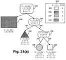
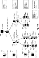
グラフィックオブジェクトの深度は、そのオブジェクトを包含するスプライトにとってローカルである。これは図31(a)から図31(c)により示される。図31(a)に示すレンダリングツリーでは、ノード294は別のスプライト296及びグラフィックオブジェクト302を包含するスプライトを表現する。所有関係は有向線295及び301によりそれぞれ示される。スプライト296は、それぞれ所有関係297及び300により示されるグラフィックオブジェクト298及び299を包含する。表4はこれら全ての基本要素のローカル深度を提供する。
2.1.2. Graphic object and its depth The depth of a graphic object is local to the sprite that contains the object. This is illustrated by FIGS. 31 (a) to 31 (c). In the rendering tree shown in FIG. 31A, the
表4
−−−−−−−−−−−−−−−−−−−−−−−−−−−−−−−−−−−−
|ラベル|基本要素 |ローカル深度| 絶対深度|
|−−−+−−−−−−−−−−−−−−−−−+−−−−−−+−−−−−|
|294|スプライト | 2 | なし |
|296|スプライト | 2 | なし |
|298|グラフィックオブジェクト(円) | 1 | 3 |
|299|グラフィックオブジェクト(四角形)| 2 | 4 |
|302|グラフィックオブジェクト(三角形)| 1 | 2 |
|309|背景z−レベル | 1 | 1 |
−−−−−−−−−−−−−−−−−−−−−−−−−−−−−−−−−−−−
ローカル深度の概念は図31(a)のサブツリーの外観を見ることによって説明することができる。図31(b)はスプライト296の外観を示す(個別にレンダリングされるオブジェクト298及び299)。オブジェクト298はオブジェクト299よりも深度値が小さいので、オブジェクト298はオブジェクト299の下方に出現する。図31(c)は、グラフィックオブジェクト302及びスプライト296の外観を示す。オブジェクト302の深度値の方が小さいので、オブジェクト296の下方に出現する。スプライト296の子のローカル深度はローカル深度凡例304に従って保管される。
Table 4
-----------------------------------
| Label | Basic elements | Local depth | Absolute depth |
| --- + ---------------- + ------ + ----- |
| 294 | Sprite | 2 | None |
| 296 | Sprite | 2 | None |
298 | Graphic object (circle) | 1 | 3 |
| 299 | Graphic Object (Rectangle) | 2 | 4 |
| 302 | Graphic object (triangle) | 1 | 2 |
| 309 | Background z-level | 1 | 1 |
-----------------------------------
The concept of local depth can be explained by looking at the appearance of the subtree in FIG. FIG. 31 (b) shows the appearance of sprite 296 (individually rendered
ノード303は所有権ツリーのルートであり、全ての最上のスプライトを包含するスプライトを表現する。ルート303は、常に、最低のローカル深度(グローバル深度においても最低)において背景z−レベル309を所有する。従って、この背景z−レベルは全グラフィックオブジェクトの下方に位置する。
2.2.表示リスト
単一のフレームに対する全スプライト及び全グラフィックオブジェクトリスト(所有関係、ローカル深度、及び変換を含む)は表示リストと呼ばれる。表示リストは従来技術において周知である。ドライバモジュール615はツリーの形態で表示リストを維持する。このツリーは、所有関係の観点からスプライト及びグラフィックオブジェクトをまとめ、ローカル深度の観点から順序付けられる。図31(a)はこの構成も示す。例えば、スプライト294の子はローカル深度により順序付けられる。第1の子302は最低ローカル深度1にあり、次の子296はより高いローカル深度2にある。
2.2. Display List All sprites and all graphic object lists (including ownership, local depth, and transformation) for a single frame are called display lists. Display lists are well known in the prior art.
2.2.1.フレームレンダリング
アニメーションの各フレームにおいて、表示リストはディスプレイへとレンダリングされる前に修正されても良い。表示リストはフレーム間で保持される。
2.2.1. In each frame of the frame rendering animation, the display list may be modified before being rendered to the display. The display list is maintained between frames.
2.2.2.グラフィックオブジェクト及びz−レベル
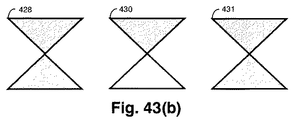
スプライトが複数のグラフィックオブジェクトを参照可能であるのと同様に、グラフィックオブジェクトは複数のz−レベルを参照することができる。これらのz−レベルの各々は、グラフィックオブジェクト内に深度を有する。例えば、図33(c)のグラフィックオブジェクトは、図33(b)に示すような深度を伴う3つのz−レベルを必要とする。
2.2.2. Graphic objects and z-levels Just as sprites can reference multiple graphic objects, graphic objects can reference multiple z-levels. Each of these z-levels has a depth within the graphic object. For example, the graphic object of FIG. 33 (c) requires three z-levels with depth as shown in FIG. 33 (b).
2.2.3.ローカル深度及び絶対深度
ドライバモジュール615内ではローカル深度が使用されるが、後続の各モジュールは絶対深度を必要とする。ドライバモジュール615は各z−レベルに絶対深度を割り当てる。
2.2.3. Local Depth and Absolute Depth Local depth is used within the
グラフィックオブジェクトのz−レベルに対する絶対深度は、ドライバモジュール615から後続の各モジュールへと渡される。これらのモジュールでは絶対深度は単に深度と呼ばれる。後続の全てのモジュールが絶対深度を割り当てられたz−レベルを用いて動作することが理解されるだろう。この割当ては、レンダリングの直前にフレームごとに行なわれる。これは、新規の表示オブジェクト又はスプライトが表示リストへと挿入された場合、あるいは、古いものが破棄された場合にのみ行なわれる。
The absolute depth for the z-level of the graphic object is passed from the
図31(a)は単一のフレームに対する全基本要素を示すものとすると、上記表4は図31(a)の全基本要素に対する絶対深度を示す。単一のフレームの全z−レベルに対する絶対深度は1で開始する。この1は特殊な背景z−レベルに割り当てられる。z−レベルは背景z−レベルから昇順に並んだ連続整数により番号付けされる。スプライトはそれ自体が絶対深度を持つことはない(子孫の深度についての情報を記録する可能性はある)。スプライトは、包含する描画オブジェクトに関連する情報(例えば、配置変換)のコンテナとして存在するが、それ自体は描画オブジェクトではない。レンダリングパイプラインの後続のモジュールはスプライトを使用しない。グラフィックオブジェクトはドライバモジュール615の外側には存在しない。グラフィックオブジェクトのローカル深度はグラフィックオブジェクトを構成する描画基本要素により参照されるz−レベルの絶対深度を計算するのに使用される。
If FIG. 31 (a) shows all the basic elements for a single frame, Table 4 above shows the absolute depth for all the basic elements of FIG. 31 (a). The absolute depth starts at 1 for all z-levels in a single frame. This 1 is assigned to a special background z-level. The z-levels are numbered by consecutive integers arranged in ascending order from the background z-level. Sprites do not have absolute depth themselves (possibly recording information about the depth of descendants). A sprite exists as a container for information (for example, arrangement conversion) related to a drawing object to be included, but is not itself a drawing object. Subsequent modules in the rendering pipeline do not use sprites. Graphic objects do not exist outside the
絶対深度は、表示リストの内容がレンダリングされる際にフレームごとに1度だけ計算される。この絶対深度を計算する方法は図44に示される。図44は表示リストツリーを示す。表示リストツリーのルートノード440は、他の全てのz−レベルの下方に位置する背景z−レベルを所有する。すなわち、背景441は最低の予想絶対深度1を有する。ノード432から439は表示リストツリーの残りの部分を構成する。
The absolute depth is calculated only once per frame when the contents of the display list are rendered. The method for calculating this absolute depth is shown in FIG. FIG. 44 shows a display list tree. The
絶対深度は、点線442により示されるツリーの深さ優先縦断中に各グラフィックオブジェクトの各z−レベルに割り当てられる。グラフィックオブジェクトのz−レベルへの絶対深度の割当ては、そのグラフィックオブジェクトにおける最低z−レベルで開始し、直「前」のグラフィックオブジェクトの最高z−レベルよりも1つ高い絶対深度が割り当てられる。「前」とは、このグラフィックオブジェクトが深さ優先縦断において先に訪れたオブジェクトであることを意味する。図44において、深さ優先縦断がグラフィックオブジェクト438に到達する様子が示される。オブジェクト438の最低z−レベルに絶対深度を割り当てるために、先に訪れたグラフィックオブジェクトであるオブジェクト435の最高z−レベルよりも1つ高い絶対深度が割り当てられる。
An absolute depth is assigned to each z-level of each graphic object during the depth-first traversal of the tree indicated by
オブジェクト438が更にz−レベルを有する場合、次に低いz−レベルから最高のレベルまで連続の絶対深度が割り当てられる。全てのスプライト及びグラフィックオブジェクトは独自のローカル深度範囲を有するのでインターリービングが不可能であることを喚起するであろう。表示リストツリーの全ノードは絶対深度を格納する。グラフィックオブジェクトは最上のz−レベルの絶対深度を格納する。スプライトは子孫の最上のz−レベルの絶対深度を格納する。ツリーの縦断は常にルートから開始する。
If the
表示リストの一部のみがノードの挿入又は削除により変更された場合、効率化のためにツリーの最小限の更新が行なわれる。表示リストツリーの縦断中、絶対深度の更新は変更された第1のノードから実行される。これより前の(縦断順)グラフィックオブジェクトのz−レベルは、それぞれの有効な絶対深度を保持する。第1の変更されたノードに到達する前に各ノードの最上の絶対深度を記録することによって、絶対深度の追跡が達成される。第1の変更されたノードに遭遇したときには、この記録された値から絶対深度の割当てが続けられる。 If only a portion of the display list is changed by inserting or deleting nodes, a minimal update of the tree is performed for efficiency. During the traversal of the display list tree, the absolute depth update is performed from the changed first node. The z-levels of graphic objects prior to this (in profile order) retain their effective absolute depth. Absolute depth tracking is achieved by recording the highest absolute depth of each node before reaching the first modified node. When the first modified node is encountered, the absolute depth assignment is continued from this recorded value.
例えば、図44において、オブジェクト438が表示リストツリーの新規のノードであり、前のフレーム以来の唯一の変更である場合、絶対深度の割当てはオブジェクト438から開始するであろう。
For example, in FIG. 44, if the
3.変換、モーフィング、及びストローキング
図56のモーフ/変換/ストローキングモジュール616は、レンダリング対象の描画オブジェクトの1つ以上の輪郭をまとめて定義するドライバモジュール615からの座標の1つ以上の順序付けられた集合を入力とする。座標の順序付けられた集合は、以下のものを含む追加のパラメータにより達成されても良い:
−モーフ率
−変換行列
−ストローク幅
−左側z−レベルへの参照
−右側z−レベルへの参照、及び
−ストロークカラーz−レベルへの参照
モーフ率、変換行列、及びストローク幅のパラメータは、グラフィックオブジェクトの輪郭を記述する座標の順序付けられた集合をディスプレイ上にどのように配置すべきかを記述する。その他のパラメータは、座標の順序付けられた集合により定義される輪郭内の表示画素に対する色、ブレンド、又はテクスチャを示すz−レベルへの参照である。
3. Transform, Morph, and Stroking The morph / transform / stroking
-Morph rate-Transformation matrix-Stroke width-Left z-level reference-Right z-level reference, and-Stroke color z-level reference Morph rate, transformation matrix, and stroke width parameters are graphical. Describes how an ordered set of coordinates describing the outline of an object should be placed on the display. The other parameter is a reference to a z-level that indicates the color, blend, or texture for the display pixel in the contour defined by the ordered set of coordinates.
図46は、モジュール616により段差のある座標の各順序付けられた集合上で行なわれる処理を示すフロー図である。この処理の目的は、段差のある座標の各順序付けられた集合(例えば、図16(a)を参照)を稜線の対応する順序付けられた集合へと変換することである。稜線の順序付けられた集合の各稜線は、少なくともレンダ空間における開始座標及び終了座標により記述される。すなわち、稜線は指向性を有する。稜線が所有するz−レベルへの左参照及び右参照は、この指向性によるものである。モーフ率、変換行列、及びストローク幅のパラメータはこの処理を制御するのに使用される。
FIG. 46 is a flow diagram illustrating the processing performed by
更に、モジュール616は、任意で1つ以上のグリフ記述を受け入れる。これらの記述は以下の情報を含む:
−グリフ位置、
−グリフ高さ/幅、
−グリフビットマップ、
−「オン」z−レベルへの参照(NULLの可能性有)
−「オフ」z−レベルへの参照(NULLの可能性有)、及び
−ステージ470においてパイプラインに入るグリフ記述
3.1.モーフィング
モジュール616がモーフオブジェクトに対応する座標の順序付けられた集合を受信する場合(すなわち、図46のステージ464=yes)、各座標の2つのバージョンがモーフ率パラメータと共に受信される。受信された座標の一方のバージョンは開始バージョンと呼ばれる。受信された座標の第2のバージョンは終了バージョンと呼ばれる。ステージ467において、モジュール616はモーフ率パラメータを使用して受信された各座標の単一の中間バージョンを補間する。例えば、図35(a)及び図35(c)は、モーフ「開始」形状及びモーフ「終了」形状をそれぞれ表現する座標の順序付けられた集合を示す。座標の順序付けられた両集合は、「論理」座標空間中の起点342で開始/終了するのが示されている。モーフプロセスの目的は、図35(a)の「開始」バージョンと図35(c)の「終了」バージョンとの間で補間することによって、図35(b)に示されるような形状の中間バージョンを生成することである。各座標のバージョン(「開始」及び「終了」)は、座標対の順序付けられた集合として提示される。この例では、339と346とが第1の対であり、それに続くのが、343と340の対、344と347の対、及び最後の対341と342である。モーフ率は各座標対からの中間バージョンを補間するのに使用される。モーフ率0が図35(a)の「開始」形状を表現するのに使用され、モーフ率1が図35(c)の「終了」形状を表現するのに使用される場合、モーフ率0.25は図35(b)に示す形状に対応するであろう。従って、モーフプロセスは出力として350、351、352、及び353により示される座標の順序付けられた集合を生成するであろう。
Further,
-Glyph position,
-Glyph height / width,
-Glyph bitmap,
-Reference to “on” z-level (possibly NULL)
A reference to “off” z-level (possibly NULL), and a glyph description that enters the pipeline at
3.2.変換
次に、図46のステージ468において、変換行列が各座標に適用される。変換行列により、座標(及び描画オブジェクト)の回転、スケーリング、及び/又は平行移動を指定することができる。この記述では、変換行列は「論理空間」から「レンダ空間」へと座標(及びそれが記述する描画オブジェクト)を変換するものとされる。
3.2. Transformation Next, at
3.3.稜線の生成
座標の順序付けられた集合がモーフィングされ(必要に応じて)、変換された後、図46のフローチャートの後続のステージ465において、座標の順序付けられた集合が稜線の順序付けられた集合へと変換される。ステージ465の達成方法の例は図15のフローチャートにより示される。この例では、座標が3つの型の描画基本要素のうちの1つの一部を形成可能であることを想定している。3つの型とは、直線、2次ベジェ曲線、及び新規の描画位置である。例では、どの型の描画基本要素が後続するか及び描画基本要素の終了にいつ到達するかを示すために追加の情報(例えば、タグバイト)が設けられることも想定している。
3.3. Edge Generation After the ordered set of coordinates is morphed (if necessary) and transformed, in a
まず図15に示すように、ステップ140において現在の描画位置が(0,0)に初期化される。続いて、ステップ124、125、126、及び127において、次に遭遇する「続く」描画基本要素の型が判定される。
First, as shown in FIG. 15, in
続く座標が新規の描画位置を記述することを型が示す場合(ステップ124)、ステップ128において座標が読み出され、ステップ131において新規の現在の描画位置を設定するのに使用される。
If the type indicates that the following coordinates describe a new drawing position (step 124), the coordinates are read in
続く座標が直線稜線を記述することを型が示す場合(ステップ125)、ステップ129において現在の描画位置と等しい開始座標が与えられる新規の直線稜線が生成される。ステップ132において座標が読み出される。この座標は、ステップ134における新規の直線稜線の終了座標及びステップ136における新規の描画位置の双方に使用される。
If the type indicates that the following coordinates describe a straight edge (step 125), a new straight edge is generated at
続く2つの座標が(例えば、2次ベジェ)曲線を記述することを型が示す場合(ステップ126)、ステップ130において現在の描画位置と等しい開始座標を持つ新規の曲線が生成される。ステップ133において第1の座標が読み出され、ステップ135において新規の曲線の「制御点」座標として使用される。ステップ137において第2の座標が読み出され、ステップ138における新規の曲線の終了座標及びステップ139における新規の描画位置として使用される。
If the type indicates that the next two coordinates describe a curve (eg, a quadratic Bezier) (step 126), then a new curve with a starting coordinate equal to the current drawing position is generated at step. In
ステップ127において、処理は座標の順序付けられた集合が終了に到達するまで継続する。
In
3.4.ストロークの稜線及びz−レベルへの分解
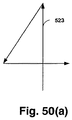
図46に戻って、処理の次のステップはステップ471において任意で選択されるストローキングステップ466である。ストローキングは、ある特定の太さのペンを使用して曲線及びベクトルの経路をたどる効果を再現できるように1つ以上の輪郭を生成するプロセスである。ストローキングの例は、図50(a)から図50(e)に示される。図50(a)は、ストローク対象の3本の稜線523の順序付けられた集合を示す。生成されたストローク輪郭524は図50(b)に示される。図50(b)は、ある特定のペン幅525で先端が円形のペンでストローク対象の3本の稜線の経路をたどったときの効果を示している。
3.4. Decomposing Stroke Edges and Z-Levels Returning to FIG. 46, the next step in the process is a stroking
図46では、ストローキングステップ466が変換ステップ468の後に行なわれなければならないことを示唆しているが、ストローキングが変換に先立って行なわれる可能性を残すのも望ましいであろう。この場合は異なる結果が得られる。例えば、図50(a)を再度参照すると、稜線523により記述される元の形状が最初に図50(c)に示す形状526を生成するように変換され、その後にストロークされる場合、結果は図50(d)に示す形状528になるであろう。しかし、稜線523により記述される元の形状が最初にストロークされ(524)、その後に同じ変換が適用される場合、結果は図50(e)に示す形状527になる。TCIEシステム699は、任意でストローキング466の後にステップ468の座標変換を実行することによって、いずれの結果を達成することもできる。
Although FIG. 46 suggests that the stroking
尚、ストローキングについての以下の考察では、正のY軸が正のX軸に対して90度時計回りである座標系(例えば、Xが右に向かって増加し、Yが下に向かって増加する)においてストローキングが行なわれるものと想定する。 Note that in the following discussion of stroking, a coordinate system in which the positive Y axis is 90 degrees clockwise relative to the positive X axis (eg, X increases to the right and Y increases to the bottom. Suppose that stroking takes place.
モジュール616は、稜線の順序付けられた集合において稜線を繰り返し処理することによって、稜線の元の順序付けられた集合をストロークする。稜線ごとに、元の稜線の経路に中心を置いて経路に沿ってたどった先端が円形のペンのストロークの左限度及び右限度に対応する新規の左側稜線及び新規の右側稜線が生成される。閉じた形状を形成しない稜線の元の順序付けられた集合の開始及び終了におけるエンドキャップと同様に、2本の連続的な元の稜線間で結合を生成するのには楕円弧が使用される。稜線の順序付けられた集合の第1の稜線の開始座標が稜線の順序付けられた集合の最後の稜線の終了座標と等しい場合にのみ、稜線の順序付けられた集合は閉じたものとなる。
各弧は、オブジェクト空間に円弧として配置され、後続の各節で説明するプロセスを介して表示空間の楕円弧へと変換される。この基本要素は現在のところ内部的にのみ使用されているが、弧はユーザが利用可能な描画基本要素として容易に公表されるであろう。 Each arc is placed as an arc in the object space and converted into an elliptical arc in the display space through the process described in the following sections. While this primitive is currently only used internally, arcs will be easily published as drawing primitives available to the user.
3.4.1.直線稜線のストローキング
図49(a)は、ストローク対象の直線稜線473の一例を示す。この稜線は開始座標474及び終了座標472により記述される。図49(b)は、直線稜線473をストローキングした所望の結果を示す。結果は左側稜線477及び右側稜線478から構成される。
3.4.1. Stroke of straight ridge line FIG. 49A shows an example of a
直線稜線をストロークするには、
−直線稜線の方向に対して90度反時計回りの方向を有し、
−ストロークのペン幅の半分に等しい長さの
左法線ベクトル479が生成される。
To stroke a straight edge,
-Has a 90 degree counterclockwise direction with respect to the direction of the straight ridge;
A left
左側ストローク稜線及び右側ストローク稜線が、直線稜線473、474(Xs,Ys)及び472(Xe,Ye)と、左法線ベクトル479(Xn,Yn)の座標を使用して計算される。
The left and right stroke ridge lines use the
左側ストローク稜線477に対して、以下に示すように開始座標(Xs_left,Ys_left)及び終了座標(Xe_left,Ye_left)が計算される:
Xs_left=Xs+Xn Ys_left=Ys+Yn
Xe_left=Xe+Xn Ye_left=Ye+Yn
現在の稜線の座標から法線ベクトルを差し引くことによって右側ストローク稜線478が生成される:
Xs_right=Xs-Xn Ys_right=Ys-Yn
Xe_right=Xe-Xn Ye_right=Ye-Yn
3.4.2.曲線稜線のストローキング
図49(c)は、ストローク対象の曲線稜線483を示す。曲線稜線(2次ベジェ曲線又は2次多項フラグメント−QPF)は、始点480、制御点481、及び終点482により記述される。
For the
X s_left = X s + X n Y s_left = Y s + Y n
X e_left = X e + X n Y e_left = Y e + Y n
A
X s_right = X s -X n Y s_right = Y s -Y n
X e_right = X e -X n Y e_right = Y e -Y n
3.4.2. Stroking of a curved ridge line FIG. 49C shows a
図49(d)は、2本の左法線ベクトル487及び488を示す。これらの法線ベクトルはこの稜線をストロークするために生成されなければならない。2本の左法線ベクトルの双方はストロークのペン幅の半分に等しい長さを有する。2本の左法線ベクトルのうちの最初のベクトル487は、始点480から制御点481へと延出するベクトルに対して90度反時計回りである。2本の左法線ベクトルのうちの第2のベクトル488は制御点481から終点482まで延出するベクトルに対して90度反時計回りである。
FIG. 49 (d) shows two left
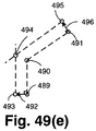
図49(e)において、始点493、制御点494、及び終点495を有する曲線の左側ストローク稜線が生成される。左側ストローク稜線の始点493(Xs_left,Ys_left)は、平行移動480により計算され、曲線稜線の開始座標(Xs,Ys)は第1の左法線ベクトル487(Xn1Yn1)により計算される:
Xs_left=Xs+Xn1 Ys_left=Ys+Yn1
左側ストローク稜線の終点(Xe_left,Ye_left)は、平行移動482により計算され、曲線稜線の終了座標(Xe,Ye)は第2の左法線ベクトル488(Xn2,Yn2)により計算される:
Xe_left=Xe+Xn2 Ye_left=Ye+Yn2
左側ストローク稜線の制御点494は2本の直線の交点を使用して計算される。第1の直線は左側ストローク稜線始点493を通り、曲線稜線始点480から曲線稜線制御点481まで延出する直線に平行である。第2の直線は左側ストローク稜線終点495を通り、曲線稜線終点482から曲線稜線制御点481まで延出する直線に平行である。
In FIG. 49 (e), a left stroke ridge line of a curve having a
X s_left = X s + X n1 Y s_left = Y s + Y n1
The end point (X e_left , Y e_left ) of the left stroke ridge line is calculated by
X e_left = X e + X n2 Y e_left = Y e + Y n2
The left stroke
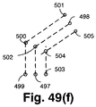
曲線の右側ストローク稜線は、始点503、制御点504、及び終点505が描かれた図49(f)の例に示すように生成される。右側ストローク稜線の始点座標(Xs_right,Ys_right)及び終点座標(Xe_right,Ye_right)は以下の式により計算される:
Xs_right=Xs-Xn1 Ys_right=Ys-Yn1
Xe_right=Xe-Xn2 Ye_right=Ye-Yn2
右側ストローク稜線の制御点504は、2本の直線の交点を使用して計算される。第1の直線は右側ストローク稜線始点503を通り、曲線稜線始点480から曲線稜線制御点481まで延出する直線に平行である。第2の直線は右側ストローク稜線始点505を通り、曲線稜線終点482から曲線稜線制御点481まで延出する直線に平行である。
The right stroke ridge line of the curve is generated as shown in the example of FIG. 49F in which the
X s_right = X s -X n1 Y s_right = Y s -Y n1
X e_right = X e -X n2 Y e_right = Y e -Y n2
The
図49(g)は、種々の制御点を参照して描かれた結果の左側ストローク稜線514及び右側ストローク稜線を示す。
FIG. 49 (g) shows the resulting left
尚、ここで説明した技術は、曲線をストロークすることの類似であり、図49(h)に示す曲線520のような急な曲線には適していない。曲線の始点517、制御点518、及び終点519により形成される三角形において、制御角は始点517及び終点519を結合する直線に対する(すなわち、向かい合う)角度として定義される。制御角が120度以下である場合、曲線は鋭角であると考えられるであろう。便利な検査は、2本の左法線ベクトル521(Xn1,Yn1)及び522(Xn2,Yn2)のドット積の大きさを使用することである:
(Xn1Xn2+Yn1Yn2)2<1/2(Xn1 2+Yn1 2)×(Xn2 2+Yn2 2)
である場合、曲線は鋭角である。
The technique described here is similar to stroke a curve, and is not suitable for a steep curve such as the
(X n1 X n2 + Y n1 Y n2 ) 2 <1/2 (X n1 2 + Y n1 2 ) × (X n2 2 + Y n2 2 )
The curve is acute.
始点、制御点、及び終点により記述される2次ベジェ曲線を2等分する方法は従来技術において周知である。鋭角であると判定された曲線稜線は、まず、2つの等価な曲線稜線へと2等分され、更に2等分される。結果的に、合計4本の曲線稜線となる。外側の2本の新規の稜線(元の鋭角に隣接しない)が上述のプロセスを使用してストロークされる。内側の2本の新規の稜線は、従来技術において周知の技術を使用して直線稜線を類似する経路へとベクトル化される。この経路は第3.4.1節で説明されるプロセスを使用してストロークされる。 A method for equally dividing a quadratic Bezier curve described by a start point, a control point, and an end point is well known in the prior art. The curved ridgeline determined to be an acute angle is first divided into two equal curved ridgelines and further divided into two equal parts. As a result, there are a total of four curved ridge lines. The outer two new edges (not adjacent to the original acute angle) are stroked using the process described above. The inner two new ridges are vectorized into similar paths using straight line ridges using techniques well known in the art. This path is stroked using the process described in Section 3.4.1.
3.4.3.結合のストローキング
追加の曲線は、経路の稜線が結合する領域をストロークするために生成されなければならない。結合は入口稜線及び出口稜線を有するように定義される。図45(a)は、結合444を形成する2本の直線稜線を示す。稜線443は結合が終点を形成するので入口稜線であり、稜線445は結合が始点を形成するので出口稜線である。左側ストローク稜線446及び447と右側ストローク稜線448及び449は上述のプロセスを使用して生成されたものである。左法線ベクトルは、入口稜線462の終了及び出口稜線463の開始に対して判定されるであろう。左側を先に考察する。入口稜線453の終了を出口稜線454の開始と接続する結合に対する曲線の輪郭を生成する必要があるか否かを判定するための検査が行なわれる。成分(Xn1,Yn1)を有する左法線ベクトル462がストローク対象の入口稜線の終点に対して既知であり、且つ成分(Xn2,Yn2)を有する左法線ベクトル463がストローク対象の稜線の開始に対して既知である場合、曲線の輪郭を生成する必要性を判定するために以下の検査を使用することができる:
Yn1Xn2<Yn2Xn1である場合、曲線稜線を使用してストロークの左側の各稜線をリンクし、直線稜線を使用してストロークの右側の各稜線をリンクする。
3.4.3. Join Stroking Additional curves must be generated to stroke the area where the path edges join. A bond is defined to have an entrance ridge and an exit ridge. FIG. 45 (a) shows two straight ridge lines forming the
If Y n1 X n2 <Y n2 X n1 , link each edge on the left side of the stroke using a curved edge and link each edge on the right side of the stroke using a straight edge.
同様に、Yn1Xn2>Yn2Xn1である場合、曲線稜線を使用してストロークの右側の各稜線をリンクし、直線稜線を使用してストロークの左側の各稜線をリンクする。 Similarly, if Y n1 X n2 > Y n2 X n1 , the curved ridge lines are used to link the ridge lines on the right side of the stroke, and the straight ridge lines are used to link the ridge lines on the left side of the stroke.
Yn1Xn2=Yn2Xn1である場合、結合を形成する各稜線は結合において同じ又は反対の方向を有する。 Y n1 X n2 = Y n2 when X is n1, each ridge line that forms a bond with the same or opposite directions in the coupling.
図45(a)に示す例では、上述の検査は曲線稜線が結合の左側に対して生成されなければならないことを示すであろう。この曲線稜線は以下の特性を有する厳密な円弧となる:
−弧の始点及び終点は点453及び454であり、
−弧の半径は左側ベクトル462の長さであり、
−弧の中心は元の経路点444であり、且つ
−弧は始点から終点まで時計回りに進む(弧は結合の右側が処理されている場合には反時計回りに進むであろう)。
In the example shown in FIG. 45 (a), the above examination will indicate that a curved edge must be generated for the left side of the join. This curved ridgeline is a strict arc with the following characteristics:
The start and end points of the arc are
The radius of the arc is the length of the
The center of the arc is the
これらの値は楕円弧の稜線を生成するのに使用され、その更なる処理については後述する。 These values are used to generate an elliptical arc ridge, and further processing is described below.
図45(a)に示す例を継続すると、上述の検査は、直線稜線が結合の右側に対して生成されなければならないことを示すだろう。結合は第1の右側稜線451の終点から第2の右側稜線450の始点までをリンクする。
Continuing with the example shown in FIG. 45 (a), the above examination will show that a straight edge must be generated for the right side of the join. The connection links from the end point of the first
図45(b)は、異なるストローク経路の同じ側の稜線455及び456が結合しない状況を示す。対応する頂点460及び461から延出し、稜線455及び456と関連付けられた制御点又は焦点を中心に湾曲するように新規の稜線を作成する。また、図45(b)は、結合しない対応する逆方向の稜線457b及び457aを示す。新規の稜線が頂点458と459との間に挿入され、経路の終結を提供する。ストロークに対する影響がゼロであるので、これは直線稜線である。
FIG. 45 (b) shows a situation where the
3.4.4.同方向又は逆方向稜線結合のストローキング
結合をストロークする技術の上記説明では、ストローク対象の結合を形成する2本の元の稜線が同じ又は反対の方向をいつ有するのかを示すための検査について述べた:
Yn1Xn2=Yn2Xn1
ここで、(Xn1,Yn1)はストローク対象の入口稜線の終了に対する左法線ベクトルであり、(Xn2,Yn2)はストローク対称の出口稜線の開始に対する左法線ベクトルである。
3.4.4. Stroking of co-directional or reverse ridge line joints The above description of the technique of stroking a joint describes an examination to show when the two original ridge lines that form the stroke object joint have the same or opposite directions. Was:
Y n1 X n2 = Y n2 X n1
Here, (X n1 , Y n1 ) is a left normal vector with respect to the end of the stroke target entrance edge, and (X n2 , Y n2 ) is a left normal vector with respect to the start of the stroke symmetric exit edge.
更に、Xn2 = Xn1である場合、左法線ベクトルは等しいため、入口稜線及び出口稜線は結合において同じ方向を有する。結合をストロークするために追加の稜線は必要とされない。 Furthermore, if X n2 = X n1 , the left normal vector is equal, so the entrance and exit edges have the same direction at the join. No additional edge is required to stroke the bond.
Yn1Xn2 = Yn2Xn1であるがXn2≠Xn1である場合、入口稜線及び出口稜線は結合において反対方向であり、後述するように結合に対してエンドキャップを生成しなければならない。 If Y n1 X n2 = Y n2 X n1 but X n2 ≠ X n1 , the entrance and exit ridges are in opposite directions in the join and must generate end caps for the join as described below .
3.4.5.経路の終了でのエンドキャップの生成
エンドキャップは、ストローク対象の閉じられていない経路の終端点に対して生成される。また、エンドキャップは入口稜線及び出口稜線の方向が反対の場合(上述のように)に稜線間の結合に対して生成されなければならない。
3.4.5. End cap generation at the end of a path End caps are generated for the end point of an unclosed path to be stroked. Also, end caps must be created for the connection between the ridges when the directions of the entrance ridge and the exit ridge are opposite (as described above).
プロセスは楕円弧を使用して終端点に対するエンドキャップを生成する。ストロークのエンドキャップの例が図18(a)に示される。図18(a)は、点193で終端するストローク対象の経路192の元の稜線を示す。左側ストローク稜線195及び右側ストローク稜線200は、それぞれ終点196及び198で終端するように描かれている。終端稜線の終点に対して成分(Xn,Yn)を有する左法線ベクトル194が示される。
The process uses an elliptical arc to generate an end cap for the end point. An example of a stroke end cap is shown in FIG. FIG. 18A shows the original ridgeline of the
エンドキャップを生成するために、楕円弧が以下の特性を有するように配置される:
−弧は左側終点196で開始し、右側終点198で終了し、
−弧の中心は元の経路点193であり、
−弧の半径は左法線ベクトル194の長さであり、
−弧は円の周りを時計回りに移動する。
有効な左z−レベル参照及び/又は有効な右z−レベル参照(有効なストロークz−レベル参照に加えて)を有する経路をストロークする際に、これはストロークされた経路が塗りつぶし対象の閉じた領域の一部を形成することを示す。このような経路に対して、任意のエンドキャップに追加の2本の直線稜線を追加する必要がある。
To create the end cap, the elliptical arc is arranged to have the following properties:
The arc starts at the
The center of the arc is the
The radius of the arc is the length of the left
-The arc moves clockwise around the circle.
When stroking a path with a valid left z-level reference and / or a valid right z-level reference (in addition to a valid stroke z-level reference), this will cause the stroked path to be filled It shows forming a part of the region. For such a path, it is necessary to add two additional straight ridge lines to any end cap.
この場合、90度時計回りに回転された終端稜線の終点に対する左法線ベクトルに等しくなるように、成分(Xn_knee,Yn_knee)を有する新規の左法線ベクトル199が作成される。続いて、終端点193(Xj,Yj)の座標及び成分(Xn_knee,Yn_knee)を有する新規の左法線ベクトル199を使用してknee座標197(Xknee,Yknee)が生成される:
Xknee=Xj+Xn_knee,Yknee=Yj+Yn_knee
図18(b)は追加の2本の稜線207a及び207bを示す。両稜線はknee点197で開始し、ストローク対象の元の稜線193の終端点で終了する。第1の追加の稜線207aは追加の左側のストロークされた稜線であり、第2の追加の稜線207bは追加の右側のストロークされた稜線である。z−レベル参照が左側のストロークされた稜線及び右側のストロークされた稜線へと割り当てられる方法が以下に記述される。
In this case, a new left
X knee = X j + X n_knee , Y knee = Y j + Y n_knee
FIG. 18B shows two additional ridgelines 207a and 207b. Both ridge lines start at the
3.4.6.ストロークされた稜線とストロークされていない稜線との間のエンドキャップ
エンドキャップは、ストローク塗りつぶしを参照する稜線がストローク塗りつぶしを参照しない稜線により経路においてたどられるときにも生成される。図28(a)は部分的にストロークされた三角形状を示す。頂点275は、ストロークされた稜線276がストロークされていない稜線277に結合する箇所である。エンドキャップが頂点275において生成される。
3.4.6. An end cap between a stroked edge and a non-stroked edge An end cap is also generated when an edge that references a stroke fill is followed in the path by an edge that does not reference a stroke fill. FIG. 28 (a) shows a partially stroked triangle. The
このエンドキャップは、前節に示したのと同じ方法、すなわち、経路の終了において生成されるエンドキャップに対して使用される同じ方法と後述する追加のステップで構成される。この方法を適用した結果が図28(b)に詳細に示されている。 This end cap consists of the same method as shown in the previous section, ie the same method used for the end cap generated at the end of the path and the additional steps described below. The result of applying this method is shown in detail in FIG.
形状の内部の塗りつぶし、すなわち、稜線278により参照される左側塗りつぶしを考慮する。これにより、小さなエンドキャップ稜線280の追加が内部の塗りつぶしが稜線の閉じた集合により完全に結ばれることを確実にすることが明らかである。稜線279、280、282、及び278は、結合の領域における形状の塗りつぶしを取り囲む稜線の集合の中にある。追加の稜線(不図示)が、結合内にない領域における塗りつぶしを取り囲む。従来技術においては周知であるが、形状を塗りつぶす方法は閉じようとする形状によって決まる−ワインディング規則及びワインディングカウントが稜線により縛られる領域を塗りつぶすのに使用される場合は特にそうである。
Consider the interior fill of the shape, ie the left fill referenced by the
図28(b)に示す稜線278は、ストローキング方法によって生成されたのではない唯一の稜線である。この稜線は入力稜線の集合から得られたものであり、出力稜線の集合に含まれる。
The
3.4.7.不透明なストロークに対するz−レベル割当て
座標の順序付けられた集合が入力として提供され、その座標の順序付けられた集合がストロークされた経路を形成する場合、左z−レベル参照及び右z−レベル参照に加えて、有用ストロークz−レベル参照及びペン幅が入力として必要である。ストロークに使用されるz−レベルと経路を塗りつぶすのに使用されるz−レベルの書式には差がない。一度座標の順序付けられた集合が稜線の順序付けられた集合へと処理されると、上述の技術を使用してストロークすることができる。モジュール616は左側ストローク稜線の集合と右側ストローク稜線の集合とを生成する。モジュール616が左z−レベル、右z−レベル、及びストロークz−レベルを入力として受け取った場合、ストロークz−レベルは不透明であると判定され、生成された左側ストローク稜線は:
−入力として受信された左z−レベルを参照する左z−レベル参照、
−入力として受信されたストロークz−レベルを参照する右z−レベル参照を割り当てられ、生成された右側ストローク稜線は:
−入力として受信されたストロークz−レベルを参照する左z−レベル参照、
−入力として受信された右z−レベルを参照する右z−レベル参照を割り当てられる。
3.4.7. Z-level assignments for opaque strokes If an ordered set of coordinates is provided as input and the ordered set of coordinates forms a stroked path, in addition to the left z-level reference and the right z-level reference Thus, a useful stroke z-level reference and pen width are required as inputs. There is no difference between the z-level format used for the stroke and the z-level format used to fill the path. Once the ordered set of coordinates has been processed into an ordered set of edges, it can be stroked using the techniques described above.
A left z-level reference that refers to the left z-level received as input,
-Assigned a right z-level reference that refers to the stroke z-level received as input, and the generated right stroke edge is:
A left z-level reference that refers to the stroke z-level received as input,
Assigned a right z-level reference that refers to the right z-level received as input.
本節では、左ストローク稜線又は右ストローク稜線への参照は、稜線の方向に従って見たときにストローク稜線の外側境界上の稜線への参照である。この点に関して、稜線がディスプレイの左上から右下へと向かうときには、左ストローク稜線は稜線の右側に出現するであろう。 In this section, a reference to a left stroke ridge line or a right stroke ridge line is a reference to a ridge line on the outer boundary of the stroke ridge line when viewed according to the direction of the ridge line. In this regard, the left stroke ridgeline will appear on the right side of the ridgeline when the ridgeline goes from upper left to lower right of the display.
このz−レベル割当てが使用される場合、ストロークされた経路の元の稜線は破棄され、生成された左側ストローク稜線及び右側ストローク稜線により完全に置き換えられる。 When this z-level assignment is used, the original edge of the stroked path is discarded and completely replaced by the generated left and right stroke edges.
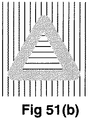
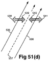
一例が図51(a)から図51(e)に示される。図51(a)は、上述のストローキング方法に対する入力稜線の集合を示し、この入力稜線が閉じた経路を定義する。稜線533、532、及び534は左z−レベル530、右z−レベル531、及びストロークz−レベル529と関連付けられる。不透明なストロークの場合、入力稜線533に対するストローキング方法から出力される稜線が、z−レベル割当てと共に図51(d)に示される。図51(a)の経路をストロークした視覚的な結果が図51(b)に示される。
An example is shown in FIGS. 51 (a) to 51 (e). FIG. 51A shows a set of input ridgelines for the above-described stroking method, and defines a path in which the input ridgelines are closed.
尚、生成された左側ストローク稜線535は、入力として提供された左z−レベル530を参照する左z−レベル参照538を有すると共に、入力として提供されたストロークz−レベル529を参照する右z−レベル参照539を有する。また、生成された右ストローク稜線536は、入力として提供されたストロークz−レベル529を参照する左z−レベル参照540を有すると共に、入力として提供された右z−レベル531を参照する右z−レベル参照541を有する。元のストローク稜線533は破棄される。
Note that the generated left
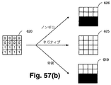
3.4.8.透明なストロークに対するz−レベル割当て
上述のものに対する代替のz−レベル割当てについて説明する。割当ては、ある程度の透明度のストロークz−レベルを有する稜線の順序付けられた集合のストローキングに特に適している。z−レベル割当てにおいて、生成された左側ストローク稜線には:
−ゼロの左z−レベル参照、
−入力として受信されるストロークz−レベルを参照する右z−レベル参照
が割り当てられ、生成された右側ストローク稜線には:
−入力として受信されるストロークz−レベルを参照する左z−レベル参照、
−ゼロの右z−レベル参照が割り当てられる。
3.4.8. Z-level assignment for transparent strokes An alternative z-level assignment for the above is described. The assignment is particularly suitable for stroking an ordered set of edges with a stroke z-level of some transparency. For z-level assignment, the generated left stroke edge is:
-Zero left z-level reference,
-A right z-level reference that refers to the stroke z-level received as input is assigned, and the generated right stroke edge is:
A left z-level reference that refers to the stroke z-level received as input,
A zero right z-level reference is assigned.
このz−レベル割当てが使用される場合、元の稜線は破棄されない−ストローキングプロセスの出力は元の稜線の集合、生成された左側ストローク稜線の集合、及び生成された右側ストローク稜線の集合の和集合である。元の稜線には、入力左z−レベル参照として提供された左z−レベル参照と入力右z−レベル参照として提供された右z−レベル参照が割り当てられる。 If this z-level assignment is used, the original edge is not discarded-the output of the stroking process is the sum of the original edge set, the generated left stroke edge set, and the generated right stroke edge set It is a set. The original edge is assigned a left z-level reference provided as an input left z-level reference and a right z-level reference provided as an input right z-level reference.
図51(a)は、上述のストローキング方法に対する入力稜線の集合を示す。稜線533、532、及び534は左z−レベル530、右z−レベル531、及びストロークz−レベル529と関連付けられる。透明なストロークの場合、入力稜線533に対するストローキング方法から出力された稜線は、z−レベル割当てと共に図51(e)に示される。図51(a)の経路をストロークした視覚的結果は図51(c)に示される。
FIG. 51A shows a set of input ridge lines for the above-described stroking method.
尚、生成された左側稜線542は、ヌルの左z−レベル参照545と入力として提供されるストロークz−レベル529を参照する右z−レベル参照546とを有する。元の稜線533は破棄されず、入力として提供される左z−レベル530を参照する左z−レベル参照550と入力として提供される右z−レベル531を参照する右z−レベル参照549とを有する。また、生成された右側稜線543は、入力として提供されるストロークz−レベル529を参照する左z−レベル参照547とヌルであることを参照する右z−レベル参照548とを有する。
Note that the generated
図63は、ストロークされることが望まれ、複数の有向稜線6302、6304、6306、及び6308により形成される経路6300を示す。図に示すように、頂点6310、6312、6314、6316、及び6318のお陰で有向稜線は延出/結合する。
FIG. 63 shows a path 6300 that is desired to be stroked and is formed by a plurality of directed
この例では、経路6300は有向稜線6302から6308の各々と関連付けられたストローク幅に従ってストロークすることが望まれる。この点に関して、有向稜線6304及び6306は同じストローク幅及び色を有し、これらの2本の稜線は一括的にストローク対象の元の経路6300の個別の部分を定義する。
In this example, path 6300 is desired to stroke according to the stroke width associated with each of directed edges 6302-6308. In this regard, directed
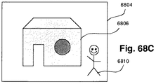
図18(a)及び図18(b)を参照して先に示したように、稜線の終了をストロークする際にアーティファクトが起こる可能性がある。特に、図63に示すように、異なるストローク幅を有する稜線が交差する(例えば、頂点6312及び6316において)場合、稜線情報から正確な合成が行なわれるように全ての稜線に対して正確なストローキングが発生することが不可欠である。この点に関して、異なるストローク幅の結果、1つのストロークが他のストロークの上に合成される可能性があり、そうなると、不透明なストロークが使用される場合に実質的なエラーを提供する可能性がある。更に、透明なストロークが使用される場合には実質的ではないが重大なエラーが発生する恐れがある。経路6300が正確にストロークされることを確実にするためには、経路6300の個別の稜線部分により形成される個々のストローク経路が正確に再生されることを確実にすることが必要である。
As previously described with reference to FIGS. 18 (a) and 18 (b), artifacts may occur when stroking the end of a ridgeline. In particular, as shown in FIG. 63, when ridge lines having different stroke widths intersect (for example, at
これは、ストローク幅が変化する元のストローク経路6300の頂点を識別することによって最初に行なわれる。図63から、ストローク幅が頂点6312及び6316において変化することが明らかである。他の全ての頂点では、ストローク幅は一定であり、作成対象の対応するストローク経路に対応する。更に、ストローク幅が変化する頂点を識別することにより、変化がない他の頂点(例えば、頂点6314)が正確にストロークされるようになる。頂点が適切に識別されると、元の経路6300の個別の部分ごとに別々のストローク経路を作成できる。稜線6302により定義される第1の個別の部分に関して、ストローク経路6320及び6322は、それぞれ頂点6312から始まり、有向稜線6302の延長線6338上に位置する頂点に向かい、頂点6310から延出する。頂点6310を中心とする経路6320及び6322のストローキングは、図18(a)において先に説明したように行なわれても良い。頂点6312を中心とする経路6320及び6322のストローキングは、図18(b)を参照して先に説明したように行なわれる。尚、図63は、頂点6312(図18(b)に示す稜線207a及び207b参照)から延出する経路6320及び6322を強調するものである。特に、ストローク経路6320及び6322は、元の経路6300の対応する個別の部分(稜線6302により形成)を一括して包囲する。
This is first done by identifying the vertices of the original stroke path 6300 where the stroke width changes. From FIG. 63 it is clear that the stroke width changes at the
稜線6304及び6306と関連付けられたストローク経路に対して同様の手法が実行される。この場合、頂点6312及び6316により定義される経路の両端部は、図18(b)において先に説明したものに対応する構成を組み込む。稜線6308と関連付けられるストローク経路6328及び6330は、稜線6302に対するものと同様に作成される。重要なことは、これらの例では、ストローク経路が、ストローク幅が変化する経路上の点にあるものとして識別される頂点を通過する必要があることである。
A similar approach is performed on the stroke paths associated with
図63の構成の拡張を図51(b)又は図51(c)を参照して理解することができるだろう。図51(b)又は図51(c)において、閉じた経路が示される。図63の構成は、個別の部分を組み込む閉じた経路が、経路の内部がネガティブワインディング規則及び図51(a)から図51(e)を参照して先に説明した塗りつぶし規則を使用して正確に塗りつぶしできるように、ストロークできるようにする。このようにして、前に説明した元の経路の稜線を左塗りつぶし及び右塗りつぶしを有するストローク経路を定義する稜線と取り換える方法は、閉じた経路の内部とストロークされた部分及びその内部に対する結果的な塗りつぶしレベルとを定義するのに使用することができる。 63 can be understood with reference to FIG. 51 (b) or 51 (c). In FIG. 51 (b) or 51 (c), a closed path is shown. The configuration of FIG. 63 is such that a closed path that incorporates individual parts is accurate using the negative winding rule and the fill rule previously described with reference to FIGS. 51 (a) to 51 (e). Enable to stroke so that it can be filled. In this way, the method of replacing the ridgeline of the original path described above with the ridgeline defining the stroke path with the left and right fills is the result of the interior of the closed path and the stroked part and its interior to the interior. Can be used to define the fill level.
3.4.9.ストローキング基本要素の変換
ストローキングがレンダ空間において行なわれる場合、ストローキングモジュールにより生成される線、ベジェ曲線、及び弧は、変換する必要がない。しかし、ストローキングがオブジェクト空間で行なわれる場合、これらの基本要素は形状の元の稜線と同じ変換を受けなければならない。
3.4.9. Conversion of Stroking Element When stroking is done in render space, the lines, Bezier curves, and arcs generated by the stroking module need not be converted. However, if stroking is done in object space, these basic elements must undergo the same transformation as the original edge of the shape.
ストローク線及びベジェ線は、第3.2節で考察したように、線及びベジェ曲線を整形するために同様の方法で変換される。一方、ストロークエンドキャップ及び結合は、別の手順を踏まなければならない。これは、アフィン変換を円弧に適用した結果が汎用的な楕円弧であるからである。 Stroke lines and Bezier lines are transformed in a similar manner to shape lines and Bezier curves, as discussed in Section 3.2. On the other hand, stroke end caps and connections must follow a different procedure. This is because the result of applying affine transformation to an arc is a general-purpose elliptic arc.
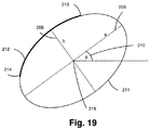
汎用型楕円弧は図19に示される。下に有る楕円211は長軸208、短軸209、中心点215、及び回転角210により記述することができる。この楕円上にある楕円弧フラグメント212は、開始Y座標213、終了Y座標214、及びフラグメント方向(時計回り又は反時計回り)の更なる提供により完全に記述される。楕円フラグメント212の場合、方向は反時計回りである。
A general-purpose elliptical arc is shown in FIG. The
下の円及び変換から楕円座標を取得するには幾つかの手法がある。1つの手法は、以下の式のpを法とする2つの解を見つけ出すことである:
tan2θ=(2ab+2cd)/(a2−b2+c2−d2)
ここで、
|a b|
Γ=| |
|c d|
は変換行列の非平行移動部分である。
There are several ways to obtain elliptical coordinates from the lower circle and transformation. One approach is to find two solutions modulo p in the following equation:
tan2θ = (2ab + 2cd) / (a 2 −b 2 + c 2 −d 2 )
here,
| A b |
Γ = |
| C d |
Is the non-translational part of the transformation matrix.
正規化された長軸ベクトル及び短軸ベクトル(楕円の中心に対して且つ単位円に関して)は、?の2つの解に対して以下の式により得られる:
|cosθ|
A=Γ| |
|sinθ|
これらの正規化された軸(又はその反対)A’は第1象限にあるだろう。事前に変換された円の半径を掛け合わせたこの軸ベクトルにより、楕円の長軸の長さ軸ベクトルが得られる。水平位置からの軸ベクトルの角度により楕円の回転が得られる。円の半径を掛け合わせた他方の軸ベクトルの長さにより楕円の短軸の長さが得られる。
What are the normalized long and short axis vectors (relative to the center of the ellipse and with respect to the unit circle)? Is obtained by the following equation:
| Cosθ |
A = Γ |
| Sinθ |
These normalized axes (or vice versa) A ′ will be in the first quadrant. This axis vector multiplied by the radius of the previously transformed circle yields the length axis vector of the major axis of the ellipse. The rotation of the ellipse is obtained by the angle of the axis vector from the horizontal position. The length of the minor axis of the ellipse is obtained by the length of the other axis vector multiplied by the radius of the circle.
楕円の中心は、ユーザが提供した変換を円の中心に適用することによって見つけられる。楕円の開始座標及び終了座標は、同じ変換を元の円の開始座標及び終了座標に適用することによって見つけられる。 The center of the ellipse is found by applying a user-provided transformation to the center of the circle. The start and end coordinates of the ellipse can be found by applying the same transformation to the start and end coordinates of the original circle.
ユーザ提供の変換は1次元で反転する。この場合、弧フラグメントの方向は変更されなければならない。変換が反転しているか否かを検査するためには、ベクトル
|1| |0|
|0|及び|1|
を取り上げ、Gを適用し、結果のベクトルの水平位置からの回転を判別するだけで十分である。2つのベクトルは180度未満の角度を刻む。
User-supplied transformations are reversed in one dimension. In this case, the arc fragment direction must be changed. To test whether the transformation is inverted, the vector | 1 | | 0 |
| 0 | and | 1 |
And applying G and determining the rotation of the resulting vector from the horizontal position is sufficient. The two vectors carve an angle of less than 180 degrees.
|1|
Γ=| |
|0|
がこの角度の反時計回り側にある場合、変換は逆である。反時計回り側にない場合、変換は逆にならない。
| 1 |
Γ = |
| 0 |
If is on the counterclockwise side of this angle, the transformation is the opposite. If it is not on the counterclockwise side, the conversion is not reversed.
3.5.フィルタリング
開始座標(Xs,Ys)及び終了座標(Xe,Ye)の観点から、曲線に対してのみは追加の制御座標(Xc,Yc)の観点から稜線を記述する座標を生成した後は、次のプロセスは明らかに出力フレームに影響しない稜線を破棄することである。これは、図46に示されるフィルタリングプロセス470である。処理のこのステージでは、稜線の全ての座標は「レンダ空間」(変換済であるので)にあり、そのため、ディスプレイの境界座標と直接比較することができる。例えば、フレームが、幅w及び高さhを有し、フレームの左上が(0,0)、右下が(w−l,h−l)により記述される場合、直線稜線は以下の場合に安全にフィルタリング(すなわち、破棄)することができる:
(Xs>=w) AND (Xe>=w) //右側に外れる場合
OR
(Ys<0 ) AND (Ye< 0) //上側に外れる場合
OR
(Ys>=h) AND (Ye>=h) //下側に外れる場合
フィルタリングのために、グリフはグリフの右上端から左下端へと伸びる直線稜線であるかのように扱われる。
3.5. Filtering From the viewpoint of the start coordinates (Xs, Ys) and the end coordinates (Xe, Ye), after generating coordinates that describe the edge from the viewpoint of additional control coordinates (Xc, Yc) only for the curve, The process is to discard edges that obviously do not affect the output frame. This is the
(Xs> = w) AND (Xe> = w) // If rightward OR
(Ys <0) AND (Ye <0) // If it is off the upper side OR
(Ys> = h) AND (Ye> = h) // When it falls to the lower side For filtering, the glyph is treated as if it were a straight ridge line extending from the upper right end of the glyph to the lower left end.
曲線(追加の制御座標を有する)に対する同様の検査は以下の通りである:
(Xs>=w)AND(Xc>=w)AND(Xe>=w) //右側に外れる場合
OR
(Ys< 0)AND(Yc< 0)AND(Ye< 0) //上側に外れる場合
OR
(Ys>=h)AND(Yc>=h)AND(Ye>=h) //下側に外れる場合
水平な直線稜線(すなわち、Ys == Ye)もフィルタリングされる。
尚、ディスプレイの左側から完全に外れた稜線は破棄されない−このような稜線は表示出力に影響しない。
A similar test for curves (with additional control coordinates) is as follows:
(Xs> = w) AND (Xc> = w) AND (Xe> = w) // If it moves to the right side OR
(Ys <0) AND (Yc <0) AND (Ye <0) // If it moves to the upper side OR
(Ys> = h) AND (Yc> = h) AND (Ye> = h) // If deviating downwards Horizontal straight edges (ie, Ys == Ye) are also filtered.
Note that edges that are completely off the left side of the display are not discarded-such edges do not affect the display output.
3.6.稜線トラッキングパラメータの生成
図46において、以下のプロセス469の目的は、稜線を修正された表現へと変換することであり、トラッキングパラメータの計算を含んでも良い。この修正された表現は、後続のモジュールによる処理により適しており、修正された表現は少なくとも以下のものを含む:
−開始座標(X,Y)、
−左z−レベルへの参照及び/又は右z−レベルへの参照、
−終了Y座標、及び
−トラッキングパラメータ。
3.6. Generation of Edge Tracking Parameters In FIG. 46, the purpose of the following
-Start coordinates (X, Y),
A reference to the left z-level and / or a reference to the right z-level,
-End Y coordinate and-Tracking parameters.
ここでは、用語「トラッキングパラメータ」は、別途記載のない限り、Yの単位増分に対して稜線のX座標を増分的に計算できるようにする1つ以上のパラメータを記述するのに使用される。例えば、直線は開始座標(Xs,Ys)、終了Y座標Ye及びY座標(すなわち、傾斜)における単位ステップ変更に対応するX座標における変更を表現するデルタX項により記述することができる。デルタX項は、稜線に対する単一のトラッキングパラメータであるだろう。 Here, the term “tracking parameter” is used to describe one or more parameters that allow the X coordinate of the ridge to be calculated incrementally relative to the Y unit increment, unless stated otherwise. For example, a straight line can be described by a delta X term that represents a change in the X coordinate corresponding to a unit step change in the start coordinate (Xs, Ys), end Y coordinate Ye, and Y coordinate (ie, slope). The delta X term will be a single tracking parameter for the edge.
TCIEシステム699は、常に左上から右下にかけてレンダリングを行なうので、稜線(直線又は曲線)は開始Y座標よりも大きい終了Y座標を有するように指定する必要がある。これは、開始Y座標と終了Y座標とを比較し、必要に応じて開始座標と終了座標とを交換することによって確実にすることができる。開始座標と終了座標とが交換される場合、左z−レベル参照及び右z−レベル参照も交換されなければならない。
Since the
3.6.1.直線稜線トラッキングパラメータの生成
直線はトラッキングパラメータとしてデルタX項を使用することで記述できることについて既に説明した。しかし、デルタXは小数データを含むことが要求されることが多い。浮動小数点又は固定小数点形式を使用してデルタXを表現する代替の方法として、より正確な表現は整数部分と傾斜のための残り部分を格納することである。
3.6.1. Generation of straight edge tracking parameters We have already explained that straight lines can be described using the delta X term as a tracking parameter. However, delta X is often required to contain decimal data. As an alternative to expressing the delta X using a floating point or fixed point format, a more accurate representation is to store the integer part and the remainder for the slope.
ソフトウェアの実現例では、このプロセスはC言語コードで実現され、傾斜の2つの部分を計算しても良い:
Grad=(Xe−Xs)/(Ye−Ys)
Ient=(Xe−Xs)%(Ye−Ys)
ここで、(Xs,Ys)は稜線の開始座標であり、(Xe,Ye)は稜線の終了座標である。
In a software implementation, this process is implemented in C language code and may calculate two parts of the slope:
Grad = (Xe−Xs) / (Ye−Ys)
Ient = (Xe−Xs)% (Ye−Ys)
Here, (Xs, Ys) is the start coordinate of the ridge line, and (Xe, Ye) is the end coordinate of the ridge line.
適切な書式で記述される稜線に対して、上述のGrad項及びIent項が、開始座標(Xs,Ys)、終了Y座標(Ye)、左z−レベル参照及び右z−レベル参照、及び左フラグ(ブール値)と共に提供される:
(Xe< Xs)の場合、左フラグ = TRUE
(Xe>=Xs)の場合、 = FALSE
3.6.2.2次ベジェ曲線トラッキングパラメータの生成
上述の図46のステップ465は曲線ごとに以下のものを生成する:
−開始座標、
−制御座標、及び
−終了座標。
For edges described in the appropriate format, the Grad and Ient terms described above have start coordinates (Xs, Ys), end Y coordinates (Ye), left z-level reference and right z-level reference, and left Provided with flags (boolean):
If (Xe <Xs), left flag = TRUE
If (Xe> = Xs), = FALSE
3.6.2.2 Generating Quadratic Bezier Curve Tracking Parameters Step 465 of FIG. 46 above generates the following for each curve:
-Starting coordinates,
-Control coordinates and-End coordinates.
曲線の座標は既に変換されている(ステップ468での座標の対応する順序付けられた集合の処理中)ので、曲線の座標は「レンダ空間」中の位置に関連する。図7は、起点(アニメーション61のフレームの左上を表現)とX軸及びY軸(それぞれ63及び62)とにより示されるレンダ空間中の開始座標58、制御座標59、及び終了座標60により表現されるベジェ曲線の例を示す。開始座標58(Xs,Ys)、制御座標59(Xc,Yc)、及び終了座標60(Xe,Ye)から2次ベジェ曲線に対するトラッキングパラメータを生成するプロセスを図41を参照して説明する。 Since the coordinates of the curve have already been transformed (during the processing of the corresponding ordered set of coordinates at step 468), the coordinates of the curve are related to a position in "render space". FIG. 7 is represented by a start coordinate 58, a control coordinate 59, and an end coordinate 60 in the render space indicated by the starting point (representing the upper left of the frame of the animation 61) and the X and Y axes (63 and 62, respectively). An example of a Bezier curve is shown. A process for generating tracking parameters for a quadratic Bezier curve from the start coordinates 58 (Xs, Ys), the control coordinates 59 (Xc, Yc), and the end coordinates 60 (Xe, Ye) will be described with reference to FIG.
図41において、第1のステップ403では、開始座標、制御座標、及び終了座標が同一直線上にある場合に関して検査を行なう。同一直線上にある場合、ステップ404において、制御座標は無視され、直線稜線に対して説明されたように稜線に対するトラッキングパラメータが計算される。
In FIG. 41, in a
次のステップ405では、2次ベジェ曲線をチェックし、Yにおいて単調であるか否かを確認する(すなわち、各Y座標に対して曲線が通過する唯一の対応するX座標がある)。例えば、図7のベジェ曲線は明らかにYにおいて単調ではない。このような非単調な2次ベジェ曲線はYにおいて単調な2つの等価な曲線稜線を使用して記述される必要がある。以下の論理は、開始点(Xs,Ys)、制御点(Xc,Yc)、及び終了点(Xe,Ye)により定義される2次ベジェ曲線が2つの曲線稜線を必要とするか否かを判定するのに使用することができる:
sign()をオペランドが正の場合にブール値TRUE(及びオペランドが負の場合FALSE)を戻す関数であるとすると:
(sign(Ys−Yc)=sign(Ys−2Yc+Ye))
AND
(|Ys−Yc|<|Ys−2Yc+Ye|)
である場合、ベジェは2つの曲線稜線を必要とする。
In the
If sign () is a function that returns the Boolean value TRUE (and FALSE if the operand is negative) if the operand is positive:
(Sign (Ys−Yc) = sign (Ys−2Yc + Ye))
AND
(| Ys−Yc | <| Ys−2Yc + Ye |)
The bezier requires two curved edges.
2本の曲線稜線が必要であると判定される場合、元の非単調ベジェ上の点(Xsplit,Ysplit)は以下の公式を使用して計算される:
Xsplit={Xs(Ye−Yc)2+2Xc(Ys−Yc)(Ye−Yc)+Xe(Ys−Yc)2}/(Ys−2Yc+Ye)2
Ysplit=(YsYe−Yc2)/(Ys−2Yc+Ye)
ステップ409において、元の非単調2次ベジェを表現する2つの単調曲線稜線が以下のものを使用して作成される:
−開始座標(=元の非単調2次ベジェの開始座標(Xs,Ys))と、
−終了座標(Xsplit,Ysplit)とを有する
−第1の曲線稜線
−開始座標(Xsplit,Ysplit)と、
−終了座標(=元の非単調2次ベジェの終了座標(Xe,Ye))とを有する
−第2の曲線稜線
稜線(直線又は曲線)が開始Y座標よりも大きい終了Y座標を有するように指定される必要があることが既に示されている。これは、ステップ406において各曲線の開始Y座標と終了Y座標とを比較し、ステップ410において必要に応じて開始座標と終了座標とを取り換えることによって確実にすることができる。開始座標と終了座標とが取り換えられる場合、左z−レベル参照と右z−レベル参照も取り換えられなければならない。
次のステップ407では、曲線の一部がレンダリング中のフレームの上方にある(すなわち、Y=0がフレームの最上部を表現する場合に0未満である開始Y座標Ysを有する)場合に、曲線を切り取るように動作する。最上の座標Ytopは以下の式により判定される:
Ytop=max(0,Ys)
ここで、max(a,b)は、2つのオペラントa及びbのうちの大きい方を戻す関数である。s
次の検査では、曲線ごとに2次多項フラグメント(QPF)として曲線を記述する必要があるか否かを判定する。これは、後続の2次方程式を解く際に0での割り算を回避するのに必要である。開始点、終了点、及び制御点に基づくこの状況に対する簡易検査が以下に示すようにステップ413において行なわれる:
Ys+Ye=2Yc
は曲線がQPFであることを暗示する。
If it is determined that two curved edges are needed, the original non-monotonic Bezier point (X split , Y split ) is calculated using the following formula:
X split = {X s (Y e −Y c ) 2 + 2X c (Y s −Y c ) (Y e −Y c ) + X e (Y s −Y c ) 2 } / (Y s −2Y c + Y e 2
Y split = (YsYe−Yc 2 ) / (Ys−2Yc + Ye)
In
-Start coordinates (= original non-monotonic Bezier start coordinates (X s , Y s )),
-With the end coordinates (X split , Y split ) -the first curve edge-the start coordinates (X split , Y split );
-The end coordinate (= the end coordinate (X e , Y e ) of the original non-monotonic secondary Bezier)-the second curve edge line The edge line (straight line or curve) has an end Y coordinate greater than the start Y coordinate It has already been shown that it needs to be specified as This can be ensured by comparing the start and end Y coordinates of each curve in
In the
Y top = max (0, Y s )
Here, max (a, b) is a function that returns the larger of the two operants a and b. s
In the next test, it is determined whether the curve needs to be described as a quadratic polynomial fragment (QPF) for each curve. This is necessary to avoid division by zero when solving subsequent quadratic equations. A simple test for this situation based on the start point, end point, and control point is performed in
Ys + Ye = 2Yc
Implies that the curve is QPF.
曲線がQPFであると判定される場合、3つのトラッキングパラメータA、C、及びDがステップ411において生成される。これらのトラッキングパラメータは以下に示すように曲線の開始点、終了点、及び制御点と最上座標Ytopから得られる:
与えられる中間値は以下の通りである:
Ai={Ye(XsYe−XcYs)+Ys(XeYs−XcYe)}/(Ye−Ys)2
Ci=(4XcYc−2XsYe−2XeYs)/(Ye−Ys)2
Di=(Xs+Xe−2Xc)/(Ye−Ys)2
A、C、及びDは以下のようにして得られる:
A=Ai+CiYtop+DiYtop 2
C=Ci+Di(2Ytop+1)
D=2Di
ステップ413において曲線がQPFではないと判定される場合、トラッキングパラメータA、B、C、及びDはステップ408において生成される。A、B、C、及びDは以下の計算により開始座標、終了座標、制御座標、及び最上座標Ytopから得られる:
Xg=Xs−Xe
Yg=Ys−Ye
Xh=Xc−Xe
Yh=Yc−Ye
Yterm=Yg−2Yh
mix=XgYh−XhYg
とすると:
B=(Xg−2Xh)/Yterm 2
A=(2mix×Yh)/Yterm 2+B(Ytop−Ye)+Xe
D=(Yterm×mix2)/Yterm 4
C=(mix×Yh2)/Yterm 4+D(Ytop−Ye)
3.6.3.符号の判定
パラメータA、B、C、Dは後述のプロセスが以下の形式の式を使用して2次ベジェ曲線のX座標を追跡する際に使用する:
x=A±2√C
トラッキングパラメータを準備する際に図41の最終ステップ412は、平方根項がAに加算されるべきか、あるいは、Aから減算されるべきかを判定する。以下の擬似コードはA、Xs、Ys、Xe、Ye、及びDに基づいて使用することができる。ここで、「sign= +1」は平方根項の加算を示し、「sign= −1」は平方根項の減算を示す:
if (A > 0) sign = −1;
else if (A < 0) sign = +1;
else
{
if (Ys < Ye) sign = −1;
else sign = +1;
if (D < 0) sign = −sign;
if (Xs < Xe) sign = −sign;
}
3.6.4.楕円弧トラッキングパラメータの生成
ステップ466(図46を参照して説明)は弧ごとに以下のものを生成する:
−楕円長軸半径及び楕円短軸半径「a」及び「b」、
−水平「θ」からの楕円角(軸aの)、
−楕円中心(x,y)、
−弧の開始座標(xs,ys)及び終了座標(xe,ye)、及び
−左z−レベル参照及び右z−レベル参照
楕円はYに対してのみ曲がり、Xに対してのみスケーリングされた円として記述することができる。このため、楕円トラッキングを簡略化するために、TCIEシステム699は全ての楕円を変換された円として扱う。
If the curve is determined to be QPF, three tracking parameters A, C, and D are generated at
The intermediate values given are:
Ai = {Ye (XsYe−XcYs) + Ys (XeYs−XcYe)} / (Ye−Ys) 2
Ci = (4XcYc-2XsYe-2XeYs) / (Ye-Ys) 2
Di = (Xs + Xe−2Xc) / (Ye−Ys) 2
A, C, and D are obtained as follows:
A = Ai + CiY top + DiY top 2
C = Ci + Di (2Y top +1)
D = 2Di
If it is determined at
Xg = Xs-Xe
Yg = Ys-Ye
Xh = Xc-Xe
Yh = Yc-Ye
Y term = Yg-2Yh
mix = XgYh-XhYg
If:
B = (Xg−2Xh) / Y term 2
A = (2mix × Yh) / Y term 2 + B (Ytop-Ye) + Xe
D = (Y term × mix 2 ) / Y term 4
C = (mix × Yh 2 ) / Y term 4 + D (Y top −Ye)
3.6.3. Sign Determination Parameters A, B, C, and D are used when the process described below tracks the X coordinate of a quadratic Bézier curve using an expression of the form:
x = A ± 2√C
In preparing the tracking parameters, the
if (A> 0) sign = −1;
else if (A <0) sign = +1;
else
{
if (Ys <Ye) sign = −1;
else sign = +1;
if (D <0) sign = -sign;
if (Xs <Xe) sign = −sign;
}
3.6.4. Generate Elliptic Arc Tracking Parameters Step 466 (described with reference to FIG. 46) generates the following for each arc:
-Ellipse major axis radius and ellipse minor axis radius "a" and "b";
The ellipse angle (of axis a) from horizontal “θ”,
-Ellipse center (x, y),
-Arc start coordinates (xs, ys) and end coordinates (xe, ye), and-left z-level reference and right z-level reference. The ellipse bends only on Y and is a circle scaled only on X Can be described as: Thus, to simplify ellipse tracking, the
楕円の稜線を変換する際にトラッキングパラメータ469の計算が行なわれなければならない第1のステップは、楕円の下に位置する円を判定する。図20はこのプロセスを実証する。楕円216は斜めスロット係数により直線の楕円217と関連する。この曲がりの大きさは線218の傾斜である。この線は216の軸ではないが、楕円の最低範囲から最高範囲まで延出する線である。
The first step in which the
この線の高さ(最低点から中心へかけての)は、以下の公式によって計算することができる:
h=√{b2cos2(θ)+a2sin2(θ)}
この線(最低点から中心にかけての)は以下の式により示される:
w={cosθsinθ(b2−a2)}/h
従って、曲がり「e」は:w/hとなる。
The height of this line (from the lowest point to the center) can be calculated by the following formula:
h = √ {b 2 cos 2 (θ) + a 2 sin 2 (θ)}
This line (from the lowest point to the center) is shown by the following formula:
w = {cos θ sin θ (b 2 −a 2 )} / h
Therefore, the turn “e” becomes: w / h.
楕円217は高さhを伴う円219へと変換される。これは単に換算係数:
f=h2/(ab)
を楕円217に適用することで達成される。
The
f = h 2 / (ab)
Is applied to the
長さよりも幅の方が格段に大きい楕円(すなわち、a>>b and ?が小さい)に関しては、生成された円を変換することでは十分な解像度を得られず、結果的な楕円はむらのあるものとなる。この問題はスーパーサンプリングにより解決される−より半径の大きい円が追跡され、数本の線は変換前にまとめられる。 For an ellipse that is much larger in width than length (ie, a >> b and? Is small), transforming the generated circle does not provide sufficient resolution, and the resulting ellipse is uneven There will be something. This problem is solved by supersampling-circles with larger radii are tracked and several lines are put together before conversion.
スーパーサンプリングのための円のサイズを判定するための保守的な手法は、a>2*scale*bである間、換算係数(1に初期化)を2倍にし続けることである。この手法では、a>=b及び−90<θ<90であると想定し、−45<θ<45の場合にのみ必要である。 A conservative approach to determine the size of the circle for supersampling is to continue to double the conversion factor (initialized to 1) while a> 2 * scale * b. This approach assumes that a> = b and −90 <θ <90, and is only necessary when −45 <θ <45.
後述するように、円はBresenhamの円アルゴリズムの修正を使用して追跡される。リアルタイムオブジェクトレンダリングの性質により、Yにおいて単調増加するフラグメントのみが処理される。このため、図46のステップ469により行なわれる第2のステップは、楕円の上側又は下側の頂点を横断する弧フラグメントを2つ以上のフラグメントへと分割することである。
As described below, the circle is tracked using a modification of Bresenham's circle algorithm. Due to the nature of real-time object rendering, only monotonically increasing fragments in Y are processed. Thus, the second step performed by
この分割の1つの可能な実現例を説明する。まず、楕円開始座標及び楕円終了座標が、曲がり「e」とスケール「f」を適用することにより円の開始座標及び終了座標へと変換される。次に、以下のアルゴリズムが実行される。このアルゴリズムは、開始点(S)及び終了点(E)と方向(d)(時計回り又は反時計回り)とを受け入れる。更に入力されるのは円の最上点(T)及び最下点(B)であり、それぞれ(xc,yc-h)及び(xc,yc+h)により示される。アルゴリズムにより開始y座標、終了y座標、及び円「側面」(左又は右)から成るフラグメントのリストが生成される。 One possible implementation of this division will be described. First, the ellipse start coordinate and the ellipse end coordinate are converted into a circle start coordinate and end coordinate by applying a curve “e” and a scale “f”. Next, the following algorithm is executed. This algorithm accepts a start point (S) and end point (E) and a direction (d) (clockwise or counterclockwise). Further input are the uppermost point (T) and the lowermost point (B) of the circle, which are indicated by (xc, y c -h) and (xc, y c + h), respectively. The algorithm generates a list of fragments consisting of a start y coordinate, an end y coordinate, and a circle “side” (left or right).
図67を考察すると、S及びEのx座標が円の中心(xc,yc)のx座標に対してステップ6701において比較される。SとEとが反対側に位置する場合、ステップ6702において、円の最上部又は最下部が横断されるか否かを確認するための検査が行なわれる。検査は、Sが左側に位置し且つdが時計回りであるか、あるいは、Sが右側に位置し且つdが反時計回りであるかを検査する。真の場合、円の最上部が横断され、出力は6703において示されるようになる(T−−>S、T−−>E)。円の側面がセグメントの最低点の側から続き、6704に示す場合、出力は(T−−>S(L)、T−−>E(R))になる。図67において6704及び6705は可能な構成であり、左右対称に関連している。この考察の残りの部分では、全ての出力がセグメントの最低点の側面を継承するであろうことが理解される。ステップ6702において、円の最下部が横断されることを検査が示す場合、出力は6706において示され、可能な構成は6707及び6708において示される。ステップ6701において、S及びEが円の同じ側で見出される場合、ステップ6709において判定されるようにEがSの上方にある場合、セグメントの終点及び方向はステップ6710において示されるように取り換えられる。これにより、更なる考察が簡略化される。
Considering FIG. 67, the x-coordinates of S and E are compared in
円の同じ側にS及びEがある場合を続けて考える。ステップ6711において、S及びEが共にT及びBを横断するか、あるいは、いずれも横断しないかが判定される。条件は、S及びEが左側に位置し且つdが時計回りであるか、あるいは、S及びEが右側に位置し且つdが反時計回りであるかである。真の場合、6712において示すように、出力(S−−>E)及び可能な構成は6713及び6714において示される。偽の場合、ステップ6715において示すように、出力は(T−−>B、T−−>S、E−−>B)である。この場合、T−−>BセグメントはS及びEの反対側に位置することになる。可能な構成は6716及び6717において示される。
Consider the case where S and E are on the same side of the circle. In
3.6.5.グリフ稜線トラッキングパラメータの生成
グリフはTCIEシステムパイプライン699の下位の部分により特殊な稜線として扱われる。このため、ストローキング/モーフィング/変換モジュール616はグリフ記述を稜線記述へと変換しなければならない。
3.6.5. Generating Glyph Edge Tracking Parameters Glyphs are treated as special edges by the lower part of the
TCIEシステム699は、左稜線ではなく右稜線によりグリフを追跡する。従って、(Sx,Sy)がストローク/モーフ/変換モジュール616に提供されたグリフの左上座標である場合、Wはグリフの幅であり、Hはグリフの高さである:
−グリフ稜線の開始座標は(Sx+W-1,Sy)であり、
−左z−レベルへの参照は「イン」z−レベルに設定され、
−右z−レベルへの参照は「アウト」z−レベルに設定され、
−終了Y座標はSy+Hである。
グリフ固有のトラッキングパラメータはグリフを表現するビットマップとグリフの幅とから成る。
The
-The starting coordinates of the glyph ridge are (Sx + W-1, Sy)
The reference to the left z-level is set to the “in” z-level;
The reference to the right z-level is set to the “out” z-level;
-The end Y coordinate is Sy + H.
A glyph-specific tracking parameter consists of a bitmap representing the glyph and the width of the glyph.
4.ソーティング
ストローキング/モーフィング/変換モジュール616により生成される稜線の集合は、図56のソーティングモジュール617へと供給される。ソーティングモジュール617は、Y軸の値を1番目に優先して昇順とし、X軸の値を2番目に優先して昇順としながらこれらの稜線が順序付けられる(すなわち、稜線は厳密にYにおいてソートされ、Y値を共有する稜線の部分集合ごとにXにおいてソートされる)ように再度順序付けを行なう。レンダリングプロセスの後の各ステージが「画素順次式に」実行可能であるように、稜線はこのように順序付けられる必要がある。画素順次式とは、レンダリングが一度に1画素実行され、画面の左上の画素から開始し、画素の次の行へと下る前に画素の各行を左から右へ進み、最後に処理される画素は画面の右下にある画素である。画素順次式レンダリングは、従来のレンダリングシステムにより使用されるランダムアクセスフレーム格納を行なう必要がなく、メモリの使用を削減し、通常、レンダリング速度を向上させる。X軸及びY軸の方向及び優先順位に関してここで使用される規則は、上述のシステム699の動作に支障をきたすことなく、任意の代替の(ただし、直交の)規則と取り変えることができることは、当業者には明らかであるだろう。
4). The set of edges generated by the sorting stroking / morphing /
ソーティングモジュール617は、周知の基数ソートアルゴリズムの使用によりその機能を達成する。基数ソートアルゴリズムは、部分ソートのシーケンスを実行することによって要素の集合をソートする。部分ソートの各々は、要素ごとにソーティングインデックスの部分のみに対してソートすることによって行なわれる(各ステージで使用されるソーティングインデックスの部分は基数の対数の底2とビット長において等しい)。ソーティングインデックスのこの部分は、どのソーティングビンに要素を配置するかを選択するのに使用される。必要なソーティングビンの数は基数の数に等しい(すなわち、必要なソーティングビンの数はソーティングインデックスの各部分により表現可能な値の総数に等しい)。要素は各ソーティングビンに配置されるので、既存の順序はビン間にまたがっては破損するが、各ビン内では維持される。これにより、順次式部分ソートが前の部分ソートにより行なわれる有用なソーティング作業を取り消さないことが確実になる。各部分ソートの最後に、全ビンの内容が順番に連結され、ソート中の要素の集合は(新規の)単純なシーケンスへと復元される。第1の部分ソートは、ソーティングインデックスの最下位のビットと共に動作し、後続の部分ソートは連続的にソーティングインデックスのより重要な部分と共に動作する。
The sorting module 617 accomplishes its function through the use of well-known radix sorting algorithms. The radix sort algorithm sorts a set of elements by performing a partial sort sequence. Each of the partial sorts is performed by sorting only the sorting index part by element (the sorting index part used in each stage is equal in base length to the
基数ソートアルゴリズムは図47(a)から図47(f)により例証される。 The radix sort algorithm is illustrated by FIGS. 47 (a) to 47 (f).
図47(a)は、ソーティングを必要とする10個の要素のシーケンスを示す。各要素は2桁の8進ソーティングインデックスを有する。尚、8進の数字「0、1、2、3、4、5、6、7」は、数字との混同を回避するために記号「A、B、C、D、E、F、G、H」と取り換えられる。 FIG. 47 (a) shows a sequence of 10 elements that require sorting. Each element has a 2-digit octal sorting index. Note that the octal digits “0, 1, 2, 3, 4, 5, 6, 7” have the symbols “A, B, C, D, E, F, G, Replaced with “H”.
図47(b)は、基数8ソートの第1のステージの、図47(a)において説明した要素のシーケンスへの適用を示す。8つのソートビンが使用され、要素はソーティングインデックスの第1の部分に従ってこれらのビンに配置される。この第1の部分ソートに対して使用されるソーティングインデックスの部分は、最下位の3ビット(基数RソートはRの対数の底2にビット長が等しいソーティングインデックスの部分と共に動作することに注意;この場合は3ビット)である。ソートインデックスの最下位の3ビットは、最下位の8進数字に対応するので、第1の部分ソートは、ソーティングを必要とする要素のシーケンスの縦断として記述することができる。各要素は要素のソーティングインデックスの右端の8進数字に対応するソーティングビンに割り当てられる。
FIG. 47 (b) shows the application of the first stage of the radix-8 sort to the sequence of elements described in FIG. 47 (a). Eight sort bins are used and elements are placed in these bins according to the first part of the sorting index. The part of the sorting index used for this first partial sort is the least significant 3 bits (note that the radix R sort works with the part of the sorting index whose bit length is equal to the
図47(c)は、ソートの第2ステージを示す。このステージでは、8つのソーティングビンの全ての内容が連結され、第1のビンの内容で開始し、最後のビンまで順次処理が進められる。この結果、ソーティングを必要とする10個の要素の新規のシーケンスが得られる。尚、この結果のシーケンスは右端の8進数字に対して正しく順序付けられる。最上位の8進数字に対して正しく順序付けられることはない。 FIG. 47 (c) shows the second stage of sorting. At this stage, all the contents of the eight sorting bins are concatenated, starting with the contents of the first bin and proceeding sequentially to the last bin. This results in a new sequence of 10 elements that require sorting. Note that the resulting sequence is correctly ordered with respect to the rightmost octal digit. It is not correctly ordered with respect to the most significant octal digit.
図47(d)はソートの第3ステージを示す。このステージは、入力シーケンスが図47(c)により記述されるシーケンスであり、使用されるソーティングインデックスの部分が2番目の3ビット、すなわち、左側の8進数字(最上位の8進数字)であることを除いては、第1ステージの繰り返しである。ソーティングインデックスのこの部分は最上位のビットを含むので、この部分ソーティングステージは必要とされる最後の1つである。このステージはソーティングを必要とする要素のシーケンスの縦断として記述することができる。各要素は要素のソーティングインデックスの左端の8進数字に対応するソーティングビンに割り当てられる。 FIG. 47 (d) shows the third stage of sorting. In this stage, the input sequence is a sequence described by FIG. 47 (c), and the part of the sorting index used is the second 3 bits, that is, the left octal digit (the most significant octal digit). The first stage is repeated except for some cases. Since this part of the sorting index contains the most significant bits, this partial sorting stage is the last one needed. This stage can be described as a traversal of a sequence of elements that require sorting. Each element is assigned to a sorting bin corresponding to the leftmost octal digit of the element's sorting index.
図47(e)はソートの第4ステージを示す。このステージはソーティングビンの内容が変更され、図47(d)に示すようになっていることを除いては、第2ステージの繰り返しである。このステージでは、8つのソーティングビンの全ての内容が連結され、第1のビンの内容で開始し、最後のビンまで順次処理が進められる。この結果、ソーティングを必要とする10個の要素の新規のシーケンスが得られる。この結果のシーケンスは左端の(最上位の)8進数字に対して正しく順序付けられる。右端(最下位)の8進数字に対して正しく順序付けられることはない。尚、同一の左端8進数字を共有する新規の下位シーケンス内では、右端の8進数字の順序は正しい。結果的に、この新規のシーケンスはソーティングインデックスに従って正しく順序付けられる。シーケンスは明瞭さを期すために図47(f)に再度描画される。 FIG. 47 (e) shows the fourth stage of sorting. This stage is a repetition of the second stage except that the contents of the sorting bin are changed and are as shown in FIG. 47 (d). At this stage, all the contents of the eight sorting bins are concatenated, starting with the contents of the first bin and proceeding sequentially to the last bin. This results in a new sequence of 10 elements that require sorting. This resulting sequence is correctly ordered with respect to the leftmost (most significant) octal digit. The rightmost (least significant) octal digit is not correctly ordered. It should be noted that the order of the rightmost octal digits is correct in a new subsequence sharing the same leftmost octal digits. As a result, this new sequence is correctly ordered according to the sorting index. The sequence is redrawn in FIG. 47 (f) for clarity.
図47(a)から図47(f)は、6ビット各々のソーティングインデックスを伴う10個の要素のシーケンスの基数8ソートを例証する。基数ソートアルゴリズムの原理を2つの基数の他の整数乗、他のソートインデックスサイズ、及び他のシーケンス長にまで拡張することは、当業者には明らかであろう。尚、基数サイズが大きくなると、必要な部分ソートの数(必要な部分ソートの数は基数の対数の底2により除算をし、四捨五入したソートインデックスのビットサイズに等しい)が削減される。基数サイズが減少すると、必要なソーティングビンの数(必要なソーティングビンの数は基数の数に等しい)が削減される。ある特定のソーティングタスクに対する基数サイズの選択は、ソーティング速度とソーティングビンにより消費されるメモリとの間のトレードオフを伴うので、最適な基数サイズは、動作環境ごとに異なるであろう。
FIGS. 47 (a) through 47 (f) illustrate a radix-8 sort of a sequence of 10 elements with a 6-bit each sorting index. It will be apparent to those skilled in the art to extend the principles of the radix sort algorithm to other integer powers of the two radixes, other sort index sizes, and other sequence lengths. When the radix size is increased, the number of necessary partial sorts (the number of necessary partial sorts is equal to the bit size of the sort index obtained by dividing by the
基数ソートアルゴリズムをグラフィックスレンダリングシステムに適用する際に、使用されるソーティングインデックスは稜線の開始点のY座標とX座標とを連結することにより作成される。Y座標の後にX座標を連結することにより、ソーティング動作が最初にYにおいてソートを行ない、続いてXにおいてソートを行なうことが確実になる。稜線がソートされた後、所望の画素順次式レンダリングはすぐに実行することができる。 When applying the radix sort algorithm to the graphics rendering system, the sorting index used is created by concatenating the Y and X coordinates of the starting point of the edge. Connecting the X coordinate after the Y coordinate ensures that the sorting operation first sorts at Y and then sorts at X. After the edges are sorted, the desired pixel sequential rendering can be performed immediately.
アンチエイリアシングを吸収するために、レンダリングシステム610は小画素の正確さを伴って稜線座標を記述しても良い。アンチエイリアシングについては本文書の他の箇所で詳細に説明するが、ここで言及しているのは、稜線座標がソーティング動作に影響するためである。ソーティングは、画素順次式レンダリングを促進するために行なわれるが、ソーティングインデックスの作成時に稜線座標の小画素の詳細は破棄される。小画素の正確さが小数部分の数字内に含まれる固定小数点表現で座標が表現される場合、小数部分の桁数に等しい桁数だけ座標を右シフトすることによって容易に達成される。
To absorb anti-aliasing, the
基数ソートアルゴリズムの動作は、単純な最適化により幾分か加速することができる。この最適化には、ソーティングモジュール617の動作を前のモジュール(変換/モーフ/ストローキングモジュール616)の動作と部分的に重ねることを伴う。これらのモジュールの動作を厳密に分離する最適化されていないシステムでは、各モジュールの相互作用は以下のように記述することができる。変換/モーフ/ストローキングモジュール616は稜線の集合を作成する。これらの稜線は、変換/モーフ/ストローキングモジュール616にとって便利な順番を問わず作成され、その順序でシーケンスへと連結される。この稜線のシーケンスが完成すると、基数ソートの適用のために一緒にソーティングモジュール617へと供給される。上述の最適化を所有するシステムは、以下のテキストにおいて説明されるように各モジュールの相互作用を修正する。変換/モーフ/ストローキングモジュール616は、先に説明したように稜線を生成するが、連結は行なわない。稜線を連結する代わりに、第1の部分ソートの適用によりこれらを処理するソーティングモジュール617へと直接供給される(すなわち、稜線は最下位ビットに従ってソーティングビンへと分配される)。後続の部分ソート動作は、変換/モーフ/ストローキングモジュール616がソーティングモジュール617への稜線の供給を終了した後に行なわれる。基数ソートの第1の部分ソートは、ソーティングを必要とするオブジェクトの集合の生成中に「高速で」実行されても良く、後続の部分ソートはオブジェクトの集合が完成した後でしか実行できないので、この最適化が可能になる。
The operation of the radix sort algorithm can be somewhat accelerated by simple optimization. This optimization involves partially overlapping the operation of the sorting module 617 with the operation of the previous module (transform / morph / stroking module 616). In an unoptimized system that strictly separates the operation of these modules, the interaction of each module can be described as follows: The transform / morph / stroking
5.稜線処理
図56において明らかなように、表示リストコンパイラ608の出力は、画面上に所望の出力(単一のフレームに対して)を記述する稜線の集合である。レンダリングエンジン610は、これらの稜線の順序付けられた集合を入力とする。尚、表示リストコンパイラ608が連続的なフレームに対して稜線を準備する間に、レンダリングエンジン610が1つのフレームに対して稜線を処理できるようにするのに2重バッファ609を使用することができる。
5. Edge Line Processing As is apparent in FIG. 56, the output of the
5.1.入出力
レンダリングエンジン610を介する表示データのフローは、稜線処理モジュール614の動作で開始する。この稜線処理モジュール614のデータフローパラメータは図22(a)及び図22(b)において要約される。動画における現在のフレームは新規の稜線の順序付けられた集合232及び静止稜線の順序付けられた集合233により記述される。新規の稜線の順序付けられた集合232は、現在のフレームに対して表示リストコンパイラ608(先に説明)により生成された稜線から構成される。これらの新規の稜線232は、前のフレームに存在しないか、あるいは、前のフレームの後に新規の位置へと移動した表示オブジェクトを記述する。静止稜線の順序付けられた集合233は、前のフレーム上に新規の稜線として導入されてから存続する(移動していない)オブジェクトを記述する。
5.1. The flow of display data via the input /
フレームに対して全稜線(新規232及び静止233の双方)を処理し終わった後に、稜線処理242は出力としてz−レベル活動化モジュール613への入力として提供される交差メッセージ243の順序付けられた集合と、次のフレームのために稜線処理239により使用されることになる静止稜線241の順序付けられた集合とを生成しているだろう(すなわち、集合241は次のフレームの開始時には集合233になる)。
After processing all edges (both new 232 and stationary 233) for the frame,
稜線処理242は、現在のフレームの終了後出力表示に貢献していない稜線を破棄する役割も果たす。このような稜線は削除のためにマーク付けされる。この削除マークは外部のエンティティ(例えば、ドライバ)により配置されるため、本文書の範囲外である。各稜線が新規の稜線の順序付けられた集合又は静止稜線の順序付けられた集合から得られると、稜線処理242は稜線が削除のためにマーク付けされたか否かを確認する。マーク付けされている場合、稜線は次のフレーム241に関して静止稜線の順序付けられた集合へと転送されない。
The
5.2.トップレベルの動作
単一のフレームに対する稜線処理242の要約が図24に示される。レンダリング対象のフレームごとに、稜線処理242はディスプレイを下りながら走査線から走査線へと(行から行へ)繰り返し、新規の稜線の順序付けられた集合又は静止稜線の順序付けられた集合中の任意の稜線が現在の走査線と交差する位置を計算することによって動作する。当業者は、基本的なアルゴリズムを他の走査方向へと適用することができる。
5.2. Top Level Operation A summary of
図24において、ステップ255のフレームの処理開始時に、現在の走査線カウンタが0に初期化される(例えば、最上の走査線)。ステップ256において判定されるように、いずれかの稜線が現在の走査線と交差する場合、この稜線はステップ257において処理される。現在の走査線カウンタが最後の走査線の処理が終了したことを示す場合(ステップ258=yes)、そのフレームに対する処理が終了する。示さない場合、ステップ259において現在の走査線カウンタが増分され、後続する走査線に対する稜線の処理が行なわれる。
In FIG. 24, at the start of frame processing in
5.3.アクティブ稜線トラッキング
図22(b)は、現在の走査線257に対する稜線を処理する際の稜線処理239を介するデータのフローの概要を示す。現在の走査線と交差する(従って処理を必要とする)稜線はアクティブ稜線と呼ばれ、アクティブ稜線の順序付けられた集合236に走査順で格納される。新規の稜線又は静止稜線の開始座標が現在の走査線と交差する場合、稜線処理239は、新規の稜線234又は静止稜線235からアクティブ稜線を生成する。アクティブ稜線は新規の稜線又は静止稜線とは少々異なる書式を有する−例えば、開始座標(Xs,Ys)を有する代わりに、アクティブ稜線は走査線ごとに更新されるcurrent_Xフィールドを有する。current_Xフィールドは、稜線が現在の走査線と交差する箇所に対応する。アクティブ稜線が処理されるごとに、アクティブ稜線が後続の走査線と交差する場合、次の走査線238に対してアクティブ稜線の順序付けられた集合へとアクティブ稜線が走査順に配置される。
5.3. Active Edge Tracking FIG. 22B shows an outline of the data flow through the
図23は、単一の走査線(図24のステップ257に対応)に対する稜線処理239の動作をより詳細に示す。ディスプレイの第1の走査線をレンダリングする前に、アクティブ稜線の順序付けられた集合236が空になる。この順序付けられた集合は、稜線処理239が新規の稜線の順序付けられた集合232中の新規の稜線又は静止稜線の順序付けられた集合中の静止稜線233の開始(終了)により交差される走査線を処理するまで空のままであろう。このような走査線に到達するまで、稜線処理239はすることがない。すなわち、アクティブ稜線の順序付けられた集合が空であり(ステップ244においてyesと判定)、残存する静止稜線又は新規の稜線がない(ステップ246=yes)か、あるいは、全ての静止稜線又は新規の稜線がレーザ走査線まで開始しない(ステップ247=yes)。
FIG. 23 shows in more detail the operation of
アクティブ稜線の順序付けられた集合が空であり(ステップ244=yes)、新規の稜線又は静止稜線が現在の走査線のいずれかの箇所で開始する(ステップ246=no、ステップ247=yes)場合、新規の稜線又は静止稜線は対応する静止の順序付けられた集合又は新規の順序付けられた集合から削除され、ステップ250において処理のためのアクティブ稜線へと変換される。
If the ordered set of active ridges is empty (step 244 = yes) and a new or static ridge starts anywhere on the current scan line (step 246 = no, step 247 = yes), The new or static edge is deleted from the corresponding static ordered set or new ordered set and converted to an active edge for processing at
稜線処理239は、常に走査線に沿って走査順で(X軸増加)稜線を生成しなければならない。前の走査線を処理した結果、アクティブ稜線の順序付けられた集合に既にアクティブ稜線が存在しているかもしれない(すなわち、ステップ244=no)。既にアクティブ稜線が存在し、現在の走査線で開始する新規の稜線又は静止稜線(ステップ245=no)がある場合(ステップ248=yes)、ステップ249において次の新規の/静止稜線のX座標は次のアクティブ稜線のX座標と比較され、どちらを次に処理すべきかを判定しなければならない。3つの稜線のソース(新規、静止、及びアクティブ)が走査順で格納されているために、処理する次の稜線は常に各ソース14の次の利用可能な稜線を考慮することによって判定することができる(図2(a)参照)。
The
5.4.稜線処理の例
図2(a)における例は、三角形状15により部分的に覆われ閉塞される矩形形状14を示す動画の第1フレームの所望の出力を示す。表示画素の現在の走査線16は、この例の目的のために重畳される。現在の走査線の左端表示画素は13である。この表示画素はX座標0に対応し、右側に後続する画素はX座標1に対応し、以下同様に対応する。
5.4. Example of Edge Line Processing The example in FIG. 2A shows a desired output of a first frame of a moving image showing a
稜線処理239が図2(a)に示すフレームに対して出力を生成する前に、表示リストコンパイラ608はこのフレームに対する所望の出力を記述する4本の新規の稜線を包含する新規の稜線の順序付けられた集合を生成しているだろう(水平稜線は塗りつぶされていることに注意)。これらの4本の稜線は図2(b)の現在の走査線16と交差することが示されている。稜線19及び22は矩形に対応するz−レベルをそれぞれ活動化及び非活動化する。稜線20及び21は三角形に対応するz−レベルをそれぞれ活動化及び非活動化する。
Before the
稜線処理239が図2(b)に示す現在の走査線を処理するまでに、稜線19及び22は新規の稜線の順序付けられた集合に存在し、稜線20及び21はアクティブ稜線の順序付けられた集合に存在するであろう。稜線20及び21は、前の(高い)走査線上で新規の稜線からアクティブ稜線へと既に変換されているだろう。
By the time edge processing 239 processes the current scan line shown in FIG. 2 (b), edges 19 and 22 are in an ordered set of new edges and edges 20 and 21 are an ordered set of active edges. Will exist.
図23において概要が示されるように、稜線は現在の走査線に対して処理されることになる。要約すると、これは、例えば、稜線19を処理することを伴う(最小のXを有するため)。稜線19は、まず、任意の交差メッセージが生成される前にアクティブ稜線へと変換される。稜線20及び21は次に処理され、最終的に稜線22がアクティブ稜線へと変換されて処理されるだろう。この例では、現在の走査線に対する4本の稜線の処理は、図2(c)に示す交差メッセージの集合を生成する。これらのメッセージの生成及び書式については第5.8節で詳細に説明する。
As outlined in FIG. 23, the edge will be processed for the current scan line. In summary, this involves, for example, processing edge 19 (because it has the smallest X).
5.5.稜線のアクティブ稜線への変換及び稜線持続性
図23に戻ると、処理する次の稜線が新規の稜線又は静止稜線の順序付けられた集合において始まる場合、ステップ250においてその稜線は最初に処理の都合上アクティブ稜線へと変換されなければならない。集合において始まらない場合、ステップ251において次のアクティブ稜線が得られる。処理する次の稜線が新規の稜線又は静止稜線であり、その新規の稜線又は静止稜線が削除のためにマーク付けされていない場合、新規の稜線又は静止稜線は次のフレームのために静止稜線237の順序付けられた集合へと配置されることになる。これにより、稜線は複数のフレームにわたって存続することができる。特定のフレーム上の稜線の削除を可能にするメカニズムを実現するのには種々の方法がある。1つの技術は、全ての稜線に識別フィールドを割り当てることであり、フレームごとにそのフレーム上で削除されるべき稜線に対応する識別フィールドの集合を提供することを考慮に入れている。代替の技術は、稜線により参照されるz−レベル内でフラグを提供し、全ての参照稜線が削除されることを示すことである。
5.5. Converting Edges to Active Edges and Edge Persistence Returning to FIG. 23, if the next edge to process begins in a new edge or an ordered set of stationary edges, then in
5.5.1.静止稜線の持続性
静止稜線バッファの動作の一例が図68Aから図68C及び図69Aから図69Cにおいて示される。図68Aから図68Cは、アニメーションシーケンスの3つのフレーム6800、6802、及び6804を示す。図68Aは、家6806から成る第1のフレーム6800を示す。図68Bは、前のフレーム6800から家6806を保持するが、家6806の戸口に立つ人6806を追加する第2のフレーム6802を示す。図68Cは第3のフレーム6804を示し、このフレームは家6806を保持するが、人が戸口から家6806の右側の位置6810へと移動している。
5.5.1. Static Edge Persistence An example of the operation of the static ridge buffer is shown in FIGS. 68A-68C and 69A-69C. 68A-68C show three
図69Aから図69Cは、それぞれ図68Aから図68Cに示すフレームを生成するのに必要な処理動作の時系列を示す。図68Aに示すように、家6806を表現するオブジェクトは、まず、表示リストコンパイラ608へと入力され、新規の稜線バッファ6901を生成する。新規の稜線バッファ6901は、現在のフレーム6800に追加される新規の稜線を含む。上述の図16(a)は、家の形状の輪郭を描く座標と、これらの座標がどのように解釈され、新規の稜線バッファ6901により保持される稜線を生成するかを指し示す。入力の静止稜線バッファ6902は、前のフレームから保持される静止稜線を含む。バッファ6901及び6902は、レンダリングエンジン610を介してレンダリングされ、現在のフレーム6800のレンダリングされた表示6903を出力する。また、図69Aは、出力の静止稜線バッファ6904を示す。出力の静止稜線バッファ6904は、後続のフレームのために保持される静止稜線を含む。
69A to 69C show time series of processing operations required to generate the frames shown in FIGS. 68A to 68C, respectively. As shown in FIG. 68A, the object representing the
図69Aにおいて、表示リストコンパイラ608は、変換、ストローキング、モーフィング、及びソーティングにより図16(a)の座標を処理する。この例では、モーフィング又はストローキングは必要ないが、表示リストコンパイラ608は座標の正しい画面位置への変換及び稜線を画面順へとソートすることに時間を費やす。処理された稜線は、レンダリング動作に備えて新規の稜線バッファ6901へと配置される。入力の静止稜線バッファ6902は空であるが、これはアニメーションにおける最初のフレーム6800であるからである(従って、前のフレームから稜線が保持されている可能性はない)。稜線バッファ6901及び6902の準備が整うと、表示リストコンパイラ608はこのフレーム6800に対する動作を中止し、レンダリングエンジン610がこのフレーム6800に対する動作を開始する。レンダリングエンジン610は、稜線バッファ6901及び6902からの各稜線をマージし、ディスプレイ6903へとレンダリングし、後続のフレームに対して保持される稜線を出力の静止稜線バッファ6904へと出力する。アニメーションのこのフレーム6800の処理が完了する。
In FIG. 69A, the
図68B及び図68Cにおいて、参照6808及び6810は、第2及び第3のアニメーションフレーム6802及び6804へとレンダリングされる人の形状の輪郭を描く座標をそれぞれ参照する。 In FIGS. 68B and 68C, references 6808 and 6810 refer to coordinates that outline the human shape to be rendered into second and third animation frames 6802 and 6804, respectively.
図69Bにおいて、アニメーションの第2のフレーム6802の処理が行なわれる。図69Bの入力の静止稜線バッファ6902は図69Aの出力稜線バッファ6904と同じである。これが可能であるのは、入力及び出力の静止稜線バッファがフレーム間で「ピンポン方式で」取り換えられるからである。図69Bの出力の静止稜線バッファ6904は「ピンポン」取換えの直後にクリアされる。
In FIG. 69B, processing of the
表示リストコンパイラ608は、このフレーム6802に対して追加される新規の稜線の座標6808を処理し、処理された稜線を新規の稜線バッファ6901に配置する。家6806の稜線は表示リストコンパイラ608による処理を必要としないが、既に処理された形態の前のフレームから保持されないからである。静止稜線技術が必要な処理時間を削減するのはこのためである。
The
前のフレームの処理におけるのと同様に、表示リストコンパイラ608は停止させられ、レンダリングエンジン610がこのフレーム6802の処理を開始する。稜線バッファ6901及び6902の内容はマージされ、ディスプレイ6903へとレンダリングされ、次のフレーム6804に対して保持される稜線は出力稜線バッファ6904に格納される。
As in the processing of the previous frame, the
図69Cにおいて、アニメーションの第3のフレーム6804の処理が行なわれる。表示リストコンパイラ608は、このフレーム6804に対して追加される新規の稜線の座標6810を処理し、処理された稜線を新規の稜線バッファ6901に配置する。前のフレーム6802と同様に、家6806の稜線は表示リストコンパイラ608による処理を必要としない。既に処理された形態で前のフレームから保持されるからである。人の形状の稜線は、人の形状6810が移動して前のフレームに比べて大きくなっているので処理を必要としない。このため、表示リストコンパイラ608は座標6810を処理し、人の形状の処理された稜線を新規の稜線バッファ6901に配置する。
In FIG. 69C, the
先に述べたように、表示リストコンパイラ608は停止させられ、レンダリングエンジン610がこのフレーム6804の処理を開始する。稜線バッファ6901及び6902の内容はマージされ、ディスプレイ6903へとレンダリングされ、次のフレームに対して保持される稜線は出力静止稜線バッファ6904に格納される。尚、家のオブジェクト6806は、アニメーションの第4のフレームに含めるために変更なしに保持されるものと想定される。変更なしに保持されない場合、家の形状は出力の静止稜線バッファ6904に含まれないであろう。
As described above, the
5.6.アクティブ稜線処理
ステップ252における次のアクティブ稜線の処理は、後続のモジュールz−レベル活動化モジュール613に渡す1つ以上の交差メッセージを生成することを伴う。各メッセージはアクティブ稜線の左z−レベル参照及び右z−レベル参照と共にcurrent−X座標を含む。
5.6. Active Edge Processing The processing of the next active edge in
アクティブ稜線が、少なくとも次の走査線まで続いている場合(図23においてステップ253=no)、ステップ254においてアクティブ稜線は次の走査線の間の処理に対するアクティブ稜線の順序付けられた集合に追加される。
If the active edge continues at least to the next scan line (step 253 = no in FIG. 23), in
5.7.稜線のトラッキング
図23のステップ252において行なわれるように、走査線から走査線へと稜線のX座標を追跡するプロセスは、従来技術において「稜線トラッキング」と呼ばれることが多い。説明したシステム699では、稜線は直線、2次ベジェ曲線、楕円弧、又は2次多項フラグメントとすることができる。
5.7. Edge Tracking As in
5.7.1.直線のトラッキング
Bresenhamの線アルゴリズムは、直線を描く方法として従来技術において周知である。ステップ252において、稜線処理239は、修正されたBresenhamのアルゴリズムを使用して走査線ごとにアクティブ直線稜線のX座標を計算する。図5のC言語ソースコードは、開始座標(Xs,Ys)から終了座標(Xe,Ye)までの直線を追跡(及び描画)するのに使用される修正されたBresenhamのアルゴリズムの一例を示す。この例は3つの事前に計算された値:err、delta_err1、及びdelta_err2に基づいてYsからYeの範囲でY座標ごとに増分的に計算される線のX座標を示す。
5.7.1. Straight line tracking
Bresenham's line algorithm is well known in the prior art as a method of drawing a straight line. In
直線である稜線に対するデータが表示リストコンパイラ608により生成される場合(第3.6.1節−直線稜線のトラッキングパラメータの生成−参照)、少なくとも以下のものを含むように生成される:
−開始座標(Xs,Ys)、
−終了Y座標(Ye)、
−整数傾斜項(grad)、
−残り傾斜項(ient)、
−左フラグ、及び
−左z−レベル及び/又は右z−レベル
ステップ250において直線稜線がアクティブ直線稜線へと変換されると、ient項がerr、delta_err1、及びdelta_err2により置き換えられる。err、delta_err1、及びdelta_err2は直線稜線のデータから以下に示すように計算される:
ty=Ye−Ys
とすると:
err=(2×ient)−ty
delta_err1=2×ient
delta_err2=2×(ient−ty)
走査線ごとに、アクティブ稜線に対する新規のcurrent−X座標が、修正されたBresenhamのアルゴリズムを使用してgrad、err、delta_err1、及びdelata_err2パラメータからステップ252に従って以下に示すように計算することができる:
errが0未満の場合:
err=err+delta_err1
current_X=current_X+grad
0以上の場合
err=err+delta_err2
current_X=current_X+grad
左フラグがTRUEの場合:
current_X=current_X−1
TRUEでない場合
current_X=current_X+1
5.7.2.2次ベジェのトラッキング
2次ベジェは、図7の例に示すように開始点、終了点、及び制御点により記述される。2次ベジェ曲線である稜線に対するデータが表示リストコンパイラ608により処理される場合(第3.6.2節−2次ベジェ曲線トラッキングパラメータ−参照)、2次ベジェ稜線記述は、少なくとも以下のものを含むように再度書式化され稜線処理239に提示される:
−開始座標(Xs,Ys)、
−終了Y座標(Ye)、
−トラッキングパラメータA、B、C、及びD、
−符号フラグ(+1又は−1)、及び
−左z−レベル及び/又は右z−レベルへの参照
図23のステップ252において、走査線ごとに、ベジェ曲線のcurrent_X位置が、以下に示すようにA、B、C、及びDに基づいて再計算される:
A=A+B
C=C+D
符号フラグが+1の場合:
Current_x=A+2√C
+1でない場合:
Current_x=A−2√C
5.7.3.2次多項フラグメントのトラッキング
表示リストコンパイラ608(第3.6.2節−2次ベジェ曲線トラッキングパラメータ−の生成参照)は、少なくとも以下のものを含むように2次多項フラグメントに対する稜線記述を生成する:
−開始座標(Xs,Ys)、
−終了Y座標(Ye)、
−トラッキングパラメータA、C、及びD、及び
−左z−レベル及び/又は右z−レベルへの参照
ステップ252において、走査線ごとに、2次多項フラグメントのcurrent_X位置が、以下に示すようにA、C、及びDに基づいて再計算される:
A=A+C
C=C+D
Current_X=A
5.7.4.楕円弧のトラッキング
表示リストコンパイラ608は少なくとも以下のものを含む楕円弧に対して稜線記述を生成する:
−等価な円中心(Cx,Cy)
−等価な円半径「R」、
−等価な円開始座標(Sx,Sy)、
−開始誤差値「E」、
−円から楕円への変換(曲がり「e」+スケーリング「f」)、
−終了Y座標「Ey」、及び
−左向き又は右向き
図23のステップ250がこのデータをアクティブ楕円弧へと変換する場合、現在の座標、現在のエラー値、及び現在のモード(後述)がこのデータにより初期化される。
トラッキングアルゴリズムは、円の中心に対する座標を追跡する。このため、現在の座標は開始座標−等価な円中心に設定される。現在のエラー値は表示リストコンパイラ608により提供されるエラー値に設定される。モードは現在走査中の8分角を追跡するのに使用され、ステップ250において提供された開始座標に基づいて初期化される。
尚、いずれのステージにおいても、絶対楕円座標は以下の公式を使用して相対的な現在座標(cx,cy)から得ることができる:
(SEx,SEy) (fcx+ecy+Cx,cy+Cy)
各円は、Bresenhamの円アルゴリズムを使用して追跡され、現在座標及びエラー値が繰り返し更新される。従来技術において周知のこのアルゴリズムは、円の右上の8分角(図14の8分角120)のみを追跡し、反映のシーケンスを使用して他の7つの8分角を生成する。更なる詳細については、「Computer Graphics: Principles and Practice」(Foley & Van Dam Second Edition)の第3.3節Scan Converting Circlesにおいて見出すことができるだろう。
When data for a straight edge is generated by the display list compiler 608 (see Section 3.6.1-Generation of tracking parameters for a straight edge), it is generated to include at least the following:
-Start coordinates (Xs, Ys),
-End Y coordinate (Ye),
An integer slope term (grad),
-The residual slope (ent),
When a straight edge is converted to an active straight edge in the left flag and -left z-level and / or right z-
ty = Ye-Ys
If:
err = (2 × ient) −ty
delta_err1 = 2 × ient
delta_err2 = 2 × (ient-ty)
For each scan line, a new current-X coordinate for the active edge can be calculated from the grad, err, delta_err1, and delta_err2 parameters using the modified Bresenham algorithm as shown below according to step 252:
If err is less than 0:
err = err + delta_err1
current_X = current_X + grad
When 0 or more err = err + delta_err2
current_X = current_X + grad
If the left flag is TRUE:
current_X = current_X-1
If not TRUE current_X =
5.7.2.2 Secondary Bezier Tracking The secondary Bezier is described by a start point, an end point, and a control point as shown in the example of FIG. When data for a ridgeline that is a quadratic Bezier curve is processed by the display list compiler 608 (see section 3.6.2-secondary Bezier curve tracking parameter), the secondary Bezier ridgeline description must be at least the following: Reformatted to include and presented to edge processing 239:
-Start coordinates (Xs, Ys),
-End Y coordinate (Ye),
-Tracking parameters A, B, C and D,
Reference to sign flag (+1 or -1) and -left z-level and / or right z-level In
A = A + B
C = C + D
If the sign flag is +1:
Current_x = A + 2√C
If not +1:
Current_x = A-2√C
5.7.3.2 Tracking Quadratic Polynomial Fragments The Display List Compiler 608 (see Section 3.6.2-Generating Quadratic Bézier Curve Tracking Parameters) contains quadratic polynomial fragments to include at least: Generate an edge description for:
-Start coordinates (Xs, Ys),
-End Y coordinate (Ye),
-Tracking parameters A, C, and D, and-Reference to left z-level and / or right z-level. In
A = A + C
C = C + D
Current_X = A
5.7.4. Elliptic arc tracking
-Equivalent circle center (Cx, Cy)
-Equivalent circle radius "R",
-Equivalent circle start coordinates (Sx, Sy),
-Start error value “E”,
-Conversion from circle to ellipse (bend "e" + scaling "f"),
-End Y coordinate "Ey", and-Left or right direction If
The tracking algorithm tracks coordinates relative to the center of the circle. For this reason, the current coordinates are set to the start coordinates minus the equivalent circle center. The current error value is set to the error value provided by the
At any stage, absolute elliptical coordinates can be obtained from the relative current coordinates (c x , c y ) using the following formula:
(SE x , SE y ) (fc x + ec y + C x , c y + C y )
Each circle is tracked using Bresenham's circle algorithm, and the current coordinates and error values are iteratively updated. This algorithm, well known in the prior art, only tracks the upper right 8th arc (
5.7.5.グリフのトラッキング
アクティブグリフオブジェクトは、グリフビットマップへの現在のポインタを維持する。このポインタは、グリフ稜線が追跡されるにつれ行ごとに増分される。グリフの左側稜線は垂直であるので、現在のX位置は稜線が追跡されるに従って更新される必要はない。
5.7.5. Glyph tracking The active glyph object maintains a current pointer to the glyph bitmap. This pointer is incremented for each row as the glyph ridge is tracked. Since the left edge of the glyph is vertical, the current X position need not be updated as the edge is tracked.
5.8.アンチエイリアシング及び交差メッセージ生成
アンチエイリアシングは、追加の(小画素)解像度を使用して稜線を追跡することによって達成される。従来技術においては周知であるが、この追加の解像度は各画素のどの部分がグラフィカル基本要素により占められるかを判定するのに使用することができる。この部分(一部の従来技術では画素カバレッジと呼ばれる)は、グラフィカル基本要素の各出力画素の色への貢献を弱めるのに使用することができ、レンダリング結果が大幅に改善される。例えば、稜線の座標において、X及びYの双方で解像度が2ビット追加することができるので、X及びYの双方において解像度が4倍となる。
5.8. Anti-aliasing and intersection message generation Anti-aliasing is achieved by tracking edges using additional (small pixel) resolution. As is well known in the prior art, this additional resolution can be used to determine which portion of each pixel is occupied by a graphical primitive. This part (called pixel coverage in some prior art) can be used to weaken the contribution of the graphical primitives to the color of each output pixel, greatly improving the rendering result. For example, in the coordinates of the ridgeline, two bits of resolution can be added for both X and Y, so that the resolution is quadrupled for both X and Y.
稜線処理239が追加の解像度をどのように使用するかを図1(a)から図1(c)を参照して説明する。図1(a)は、アクティブ稜線0が現在レンダリング中の表示画素の走査線1に入るのを示す。図1(b)において、この走査線は稜線データのY座標における追加の2ビットにより提供される追加の小画素解像度を表現する4つの小画素線(spel線)3、4、5、及び6へと分割される。稜線のX位置は、先に説明した稜線トラッキング技術のうちの適切な1つを使用して、4本のspel線の各々に対して小画素の精度で繰り返し判定される。追跡中の稜線が少なくとも1本のspel線と交差する表示画素ごとに、稜線がその画素にどのように影響するかを4x4ビットマスクで表現するものが生成される。このようなビットマスクは、従来技術ではしばしばA−bufferと呼ばれる。このA−bufferが最初に記述されたのはCarpenter, L.による「The A?buffer, an Anti?aliased Hidden Surface Method」(Computer Graphics, Vol. 18, No. 3, Jul. 1984)(以降、「Carpenter」)である。A−bufferは、表示画素内のどのspelが稜線により影響されるかを示すために使用され、稜線処理モジュール614からz−レベル活動化モジュール613へと渡される交差メッセージに含まれる。この例では、図1(c)に示すように3つのA−buffer、すなわち、A−buffer8、11、及び12が生成される。これらのA−bufferは、走査線画素X=2、X=3、及びX=4に対応する。図1(c)に示すように、spel9は稜線により影響されないが、spel10は稜線により影響される。
How the
交差メッセージ及び関連するA−bufferの生成は、図23のステップ252においてアクティブ稜線に対して行なわれる。このステップについては図3を参照して詳細に説明する。
The generation of the crossing message and the associated A-buffer is performed on the active edge in
図3の第1のステップ35において、current_spel_line値が0に初期化される。これは、現在の走査線の最上のspel線が最初に処理されることを示す。A−bufferが空として初期化され、current_pixel値は、アクティブ稜線が現在の走査線に入る表示画素に対応するX値を伴って初期化される。このX値はアクティブ稜線のcurrent_X座標の非小数部分である。
In the
次にステップ36において、処理中のアクティブ稜線のcurrent_X座標はcurrent_pixel値と比較され、current_Xがcurrent_pixelにより表現される表示画素内にあるか否かが確認される。これは、ステップ35の結果としての最初の繰り返しでは真である。
Next, in
次のステップ39はcurrent_spel_lineに対応するA−bufferの単一の行を修正するように動作する。ここで、A−bufferの最上行はcurrent_spel_line=0に対応する。current_Xの小数データは、current_spel_lineに対応するA−bufferの行に幾つのspelが「設定される」べきかを判定するのに使用される。小画素の精度の2ビットが、例えば、current_Xにより提供される場合、A−buffer8、11、及び12に示すように1行当たり4つのspelを表現するA−bufferを生成することができる。表5は、current_spel_lineに対応するA−bufferの行をどのように設定すべきかを判定するのに2ビットの小数データをどのように使用することができるかを示す。
The
表5
−−−−−−−−−−−−−−−−−−−−−−−−−−−−−−−−−−−−−−−
|current_X|A−bufferの行 |
|の小数ビット |−−−−−−−−−−−−−−−−−−−−−−−−−−−|
| |左端spel 第2spel 第3spel 右端spel|
|−−−−−−−−−+−−−−−−−−−−−−−−−−−−−−−−−−−−−|
| 00b | 1 1 1 1 |
| 01b | 0 1 1 1 |
| 10b | 0 0 1 1 |
| 11b | 0 0 0 1 |
−−−−−−−−−−−−−−−−−−−−−−−−−−−−−−−−−−−−−−−
図1(b)の例に戻ると、最上spel線3に対する処理中に、(current_spel_line=0)、アクティブ稜線0に対するcurrent_X値が非小数成分4(100b)と小数成分0.75(小数ビットは11b)とを有する。この場合、A−buffer12の最上行の右端spelのみが表5に従って設定される。
Table 5
--------------------------------------
| Current_X | A-buffer line |
| Decimal bits | -------------------------- |
| | Left end spel Second spel Third spel Right end spel |
| --------- + -------------------------- |
| 00b | 1 1 1 1 |
| 01b | 0 1 1 1 |
| 10b | 0 0 1 1 |
| 11b | 0 0 0 1 |
--------------------------------------
Returning to the example of FIG. 1B, during the processing for the uppermost spel
A−bufferの修正後、図3に示すようにステップ40において以下のspel線4と交差するアクティブ稜線に対応する新規のcurrent_Xが計算される。これは、先に説明したトラッキング技術のうちの1つをアクティブ稜線に対するデータに適用することにより達成される。ステップ41においてcurrent_spel_lineは増分され、処理すべきspel線が更に存在する場合(ステップ42=no)、処理はアクティブ稜線のcurrent_Xをcurrent_pixelと比較するステップ36へと戻る。
After the correction of A-buffer, a new current_X corresponding to the active edge line intersecting the following spel
アクティブ稜線がcurrent_pixelにより示されるものと異なる表示画素内でcurrent_spel_lineと交差することをcurrent_Xが示す場合、少なくとも以下のものを含む交差メッセージを生成するステップ37が行なわれる:
−X座標=current_pixel
−A−buffer
−活動化されたz−レベル参照(アクティブ稜線の左z−レベル参照からコピー)
−非活動化されたz−レベル参照(アクティブ稜線の右z−レベル参照からコピー)
尚、z−レベル参照はヌルの塗りつぶしを参照することができる。
If current_X indicates that the current edge intersects current_spel_line in a different display pixel than that indicated by current_pixel, then step 37 is performed to generate a crossing message that includes at least the following:
-X coordinate = current_pixel
-A-buffer
-Activated z-level reference (copied from the left z-level reference of the active edge)
Deactivated z-level reference (copied from the right z-level reference of the active edge)
Note that the z-level reference can refer to a null fill.
生成された交差メッセージは、出力としてソーティング手段(例えば、ソートバッファ)を介してz−レベル活動化モジュール613に渡される。ソーティング手段は、z−レベル活動化モジュール613が走査順(すなわち、X座標の昇順にソート)交差メッセージを受信することを確実にするのに必要である。
The generated crossing message is passed as output to the z-
A−bufferは空に再初期化され、current_pixelはアクティブ稜線に対するcurrent_X値(0)の非小数部分に設定される。続いてA−bufferは、先に説明したようにA−buffer11に修正され、current_pixelのcurrent_spel_line5に対するアクティブ稜線の影響を示す。 A-buffer is re-initialized to empty, and current_pixel is set to the non-decimal part of the current_X value (0) for the active edge. Subsequently, A-buffer is modified to A-buffer 11 as described above, and indicates the influence of the active edge line on the current_spel_line5 of the current_pixel.
処理は残りのspel線6に対して継続されるため、A−buffer11を含む交差メッセージが出力される。
Since the processing is continued for the remaining
全てのspel線が処理されると(ステップ42=yes)、先に説明したようにステップ43においてA−buffer8を含む最終交差メッセージが生成され、出力される。
When all the spel lines have been processed (
5.8.1.グリフに対する交差メッセージの生成
レンダリングされたグリフの各行はバイト幅(すなわち、8画素幅)ブロックへと分割され、このブロックが順番に処理される。各バイトは256エントリルックアップテーブル(LUT)への索引として使用される。各エントリは32ビットを占める。LUTの単一のエントリは8画素行交差メッセージにおけるどの画素が生成されなければならないかを識別する。
5.8.1. Generating Crossing Messages for Glyphs Each row of rendered glyphs is divided into byte-wide (ie, 8 pixel wide) blocks that are processed sequentially. Each byte is used as an index into a 256 entry lookup table (LUT). Each entry occupies 32 bits. A single entry in the LUT identifies which pixels in the 8-pixel row crossing message must be generated.
各エントリはニブル単位で処理される−最初のニブルはバイトにより生成される交差の数を記録し、後続する各ニブルは領域の開始に対する交差の位置を記録する。8つの交差を記録するが位置を記録しない特殊なエントリは、バイトが各画素に交差を有する独特な場合に使用される。 Each entry is processed in nibbles-the first nibble records the number of intersections generated by the byte, and each subsequent nibble records the position of the intersection relative to the start of the region. A special entry that records eight intersections but not a position is used in the unique case where a byte has an intersection at each pixel.
図26において、幅16高さ2のビットマップ265を伴う例が示される。2進表現265は{0xD6,0x54,0x99,0xCC}であるだろう(尚、各バイトのビット7は対応する画素ブロックにおいて左端の画素を指し示す)。このビットマップの第1バイトを取り上げ、LUT266においてその符号なし値を参照すると、位置0、2、3、4、5、及び7に6つの交差があることが分かる。LUT266が画素座標(100,100)に配置されるものとすると、交差メッセージは(100,100)、(102,100)、(103,100)、(104,100)、(105,100)、(107,100)に対して生成されなければならないことを意味するであろう。8つの交差メッセージを生成するバイトをこの数字において観察することができる。
In FIG. 26, an example with a
LUT266が索引付けされ、バイトに対する交差の集合が得られると、余分な交差が挿入されるか、あるいは、不正確な交差が削除されても良い。これは、ビットマップの各行の開始で0に初期化されるフラグにより管理される。このビットがクリアされると、交差は修正されていない。ビットが設定されると、画素ブロックにおける左端位置(「ゼロ交差」)に対応する交差が存在しない場合、1つが挿入される。逆に、ゼロ交差が存在する場合、削除される。
Once the
フラグの状態は、行の各バイトの処理の終了時に更新される。奇数個の交差メッセージはフラグを反転させるが、偶数個の交差メッセージはフラグの現在値を維持する。フラグが行の終了で設定される場合、最終交差メッセージが出力されて行を正しく終了させる。このメッセージの位置は現在の画素ブロックの1つ右の画素ブロックの開始にある。 The state of the flag is updated at the end of processing of each byte in the row. An odd number of cross messages invert the flag, while an even number of cross messages maintain the current value of the flag. If the flag is set at the end of a line, a final crossing message is output and the line ends correctly. The position of this message is at the start of the pixel block to the right of the current pixel block.
図26に戻ると、ビットマップにおいて4バイトにまたがってこのフラグの状態を追跡することができる。第1行の開始において、フラグは0に初期化される。第1バイトは偶数の交差に分解するので、フラグはこのバイトの終了では切り換えられない。これに対し、第2のバイトは奇数の交差に分解する。結果として、フラグは1に切り換えられる。第2のバイトは行の最後であるので、行を終了させるために最終交差メッセージが生成される。 Returning to FIG. 26, the state of this flag can be tracked across 4 bytes in the bitmap. At the start of the first line, the flag is initialized to zero. Since the first byte breaks into even intersections, the flag is not switched at the end of this byte. On the other hand, the second byte breaks up into an odd number of intersections. As a result, the flag is switched to 1. Since the second byte is the end of the line, a final crossing message is generated to end the line.
第2の行に移動し、フラグが0に初期化される。第3のバイトは奇数の交差メッセージに分解し、フラグはこのバイトの終了において1に設定される。第4のバイトは、0、1、2、3、4、5、6、及び7において8つの交差メッセージに分解する。しかし、フラグは設定される。ゼロ交差メッセージが存在するので、このメッセージは削除され、結果として7つの交差メッセージが出力される。これは奇数の交差であるので、フラグは再度0に切り換えられる。処理は行の終了にあるのでフラグは設定されず、最終交差メッセージは出力されない。 Moving to the second line, the flag is initialized to zero. The third byte breaks into an odd number of crossing messages and the flag is set to 1 at the end of this byte. The fourth byte breaks down into eight crossing messages at 0, 1, 2, 3, 4, 5, 6, and 7. However, the flag is set. Since there is a zero crossing message, this message is deleted, resulting in the output of seven crossing messages. Since this is an odd number of intersections, the flag is again switched to zero. Since the process is at the end of the line, no flag is set and no final crossing message is output.
いずれにしても交差メッセージは、全ての小画素が−1に設定されているSバッファを備えている。結果として、グリフは奇偶ワインディング規則を使用して常にレンダリングされるべきである。 In any case, the crossing message has an S buffer in which all small pixels are set to -1. As a result, glyphs should always be rendered using odd-even winding rules.
5.8.1.1.グリフ交差メッセージの生成及びアンチエイリアシング
図66は図26に示すのと同じ走査線を示す。この走査線上で単一の画素6601を考慮すると、交差メッセージ6602が生成される。交差メッセージ6602は全ての小画素が−1に設定されている。この交差メッセージにより画素全体6603が出力される。要するに、グリフはアンチエイリアシングされず、小画素は考慮されない。これは、「ゼロ交差」フラグを考慮して追加されるものを含むグリフに対して生成される全ての交差メッセージに関して真実である。
5.8.1.1. Glyph Crossing Message Generation and Anti-Aliasing FIG. 66 shows the same scan lines as shown in FIG. Considering a
5.9.交差メッセージの例
図2(c)に示す例を継続すると、図2(b)に示すように、アクティブ稜線に対して稜線処理モジュール614により生成される交差メッセージを示す。この例では4x4アンチエイリアシングが使用される。4x4アンチエイリアシングでは、アクティブ稜線座標が表示画素内の小画素(spel)に対応する追加の2ビットの解像度を伴って記述される。まず稜線19の処理が行なわれ、対応する交差メッセージ23が生成されるであろう。アクティブ稜線は矩形に対する塗りつぶしを記述する左z−レベル参照を持っているので、生成された交差メッセージ23の活動化されたz−レベル参照は矩形に対する塗りつぶしを記述する活動化されたz−レベル参照を有するであろう。
5.9. Example of Crossing Message Continuing with the example shown in FIG. 2 (c), as shown in FIG. 2 (b), the crossing message generated by the
次にアクティブ稜線20の処理が行なわれる。モジュール614(図3で概略を示す)は、アクティブ稜線20に対する4つのspel線のうちの最初の3つを繰り返す際に交差メッセージ25が生成される。アクティブ稜線は異なる画素上の第4(最下部のspel線)と交差するので、これに対して異なる交差メッセージが生成される必要があるので、交差メッセージ24が次に生成される。これらの交差メッセージは、三角形に対する塗りつぶしを記述する活動化されたz−レベル参照を活動化している。
Next, processing of the
同様に、交差メッセージ26及び27がアクティブ稜線21に対して生成され、これらのメッセージが三角形に対する塗りつぶしへの非活動化されたz−レベル参照(元のアクティブ稜線21の右z−レベル参照からコピー)を有する。交差メッセージ28が稜線22から最後に生成される。このメッセージは矩形に対する塗りつぶしへの非活動化されたz−レベル参照を有する。
Similarly,
5.9.1.別の例
図70はS−bufferがゼロ交差メッセージの受信を伴って更新されるのを示す更なる例である。最初に、走査線における画素#1に関して、稜線交差はないので、この画素に対して交差メッセージ又はS−buffernは存在しない。このように、画素#1に対してS−buffernは0を伴って設定される。このS−buffernの右端列が、次の画素#2に対するS−buffern−1の第1(すなわち、左端)の列にコピーされる。この列はS−buffern−1の列をまたいでコピーされ、この場合、バッファもゼロを伴って設定される。図示するように、稜線が画素#2と交差し、下位線の交差(交差4、2又は1本の下位線)に対する説明した規則に従って、画素#2に対するゼロ交差メッセージが判定される。メッセージはより低い右側の1/4において+1が配置されるので、走査線と交差する稜線が補足される。画素#2に関して、ゼロ交差メッセージ及びS−buffern−1が合計され、その画素に対するS−buffernが与えられる。この場合、バッファはヌルであるので、これは単なる交差メッセージである。次の画素#3に関して、S−buffernから右端列がコピーされ、S−buffern−1に配置される。この場合では1が配置される。関連する稜線が画素の右上4分円において2本の下位線のみと交差することが明らかな場合、画素#3における交差メッセージが、交差規則に従って判定される。再度、交差メッセージ及びS−buffern−1が合計され、画素#3に対するS−buffernが与えられる。画素#4に関して、右端列がコピーされ、S−buffern−1をまたがって配置される。交差メッセージが規則を使用して判定され、合計されて画素#4に対してS−buffernが与えられる。交差メッセージ及びS−bufferを使用してアンチエイリアシングを実施するこの手法により、小画素ベースでレベルを合成することなしに、走査線上の画素位置に対するアクティブレベルを正確に判定できるようになる。全ての小画素プロセスは、S−buffer及び交差標識を使用して行なわれ、画素レベルで合成作業を残す。
5.9.1. Another Example FIG. 70 is a further example showing the S-buffer being updated with the receipt of a zero crossing message. Initially, for
5.10.アクティブ稜線及び交差メッセージの再順序付け
走査線に対するアクティブ稜線は走査順に処理されるが、対応する交差メッセージは必ずしも走査順(Xの昇順)に生成・出力されなくても良い。例えば、稜線20が図2(b)において処理される場合、交差メッセージ25が最初に生成・出力され、それにメッセージ24が続く。交差メッセージ25は、メッセージ24よりも高いX座標を有するので、交差メッセージは走査順には出力されない。更に、稜線処理モジュール614の動作中に新規のcurrent_Xを計算すると、第1のアクティブ稜線がこの走査線上で既に処理された第2のアクティブ稜線よりも低い走査位置を有する結果となる恐れがある。
5.10. Re-ordering of active edges and crossing messages The active edges for scan lines are processed in scan order, but the corresponding cross messages do not necessarily have to be generated and output in scan order (ascending order of X). For example, if the
この状況の例が図21に示される。ここで、2本の水平な破線230及び231は出力表示の走査線を表現する。上側の破線230は現在稜線処理モジュール614により処理されている走査線を表現し、下側の破線231は次に処理される走査線を表現する。図21は、それぞれ、交差224、225、及び226で現在の走査線230と交差する3本のアクティブ稜線221、222、及び223を示す。アクティブ稜線のcurrent_Xフィールドは交差の位置を示す。稜線処理モジュール614は次の走査線231上の交点227、228、229に対応するアクティブ稜線の各々に対して新規のcurrent_X値を計算する。この例では、これらの修正されたアクティブ稜線は走査順になっていない。アクティブ稜線223はアクティブ稜線221及びアクティブ稜線222と交差しているからである。従って、修正されたアクティブ稜線は、次の走査線に対してアクティブ稜線の順序付けられた集合に配置される前に再度のソーティングを必要とする。この例では、次の走査線に対するアクティブ稜線の順序付けられた集合におけるアクティブ稜線の所望の順序は、まず223、次に221、最後に222である。
An example of this situation is shown in FIG. Here, two horizontal
稜線処理モジュール614は、次の走査線のためにアクティブ稜線の順序付けられた集合へと転送される前に走査順になるように、修正されたアクティブ稜線をソーティング手段(例えば、ソートバッファ)へと挿入する。また、z−レベル活動化モジュール613が走査順で交差メッセージを受信するように、出力の交差メッセージ(図23のステップ252において生成されるように)をソーティング手段(例えば、ソートバッファ)を介して渡す必要がある。
6.z−レベル活動化モジュール
z−レベル活動化モジュール613は、稜線処理モジュール614から渡される稜線交点データを使用して、フレームがレンダリングされるときの出力色にどのz−レベルが貢献するかを追跡する。出力画素のストリームがレンダリングエンジン610により走査順に生成される。稜線処理モジュール614からの各交差メッセージは、走査順で生成されるときに所要の出力色が変化する表示座標を表現する。以下の説明では、特定のラスタ空間位置で開始する1つ以上の走査順の連続画素は画素のランと呼ばれる。この説明では、A−bufferが稜線交差に対して生成されることを、すなわち、レンダリングシステム610がアンチエイリアシングを行なう場合を想定する。
6). z-level activation module The z-
6.1.関心のあるz−レベルの順序付けられた集合
z−レベル活動化モジュール613は、図59に一般的に示されるように、「関心のある」z−レベルのリストを維持する。関心のあるとは、当該のz−レベルがz−レベル活動化モジュール613により考慮されなければならないことを意味する。z−レベル活動化モジュール613は、関心のあるz−レベルの順序付けられた集合を使用して交差メッセージの入力を現在の走査線に沿って画素のランに対する出力色に貢献するのがどのz−レベルであるかを示す領域メッセージの出力へと変換する。すなわち、ランは、2つの隣接する交差メッセージにより記述される各点内に位置する。
6.1. An ordered set of z-levels of interest The z-
z−レベル活動化モジュール613の動作は、交差メッセージのストリームをどの深度がスパン上にあり、スパンにまたがるのはどの相対深度順序付けであるかを示す領域メッセージの出力へと変換する観点からも見ることができる。ここでのスパンは、交差メッセージが境界となる走査線上の内部を意味する。z−レベルは深度を塗りつぶしに結合するので、深度の順序付けられた集合は、どのz−レベルが現在の走査線に沿って画素のランに対する出力色に貢献するかを判定するのに使用することができる。これが合成器の役割であり、これについては後述する。スパン上に存在するz−レベルの集合を判定することは、スパン上に存在する深度を判定するのと同等である。
The operation of the z-
6.2.z−レベル活動化モジュールにおける制御のフロー
稜線処理モジュール614と同様に、z−レベル活動化モジュール613は、レンダリングのタスクを走査線ごとに考慮し、入力(交差メッセージ)を受信することを予期する。単一の走査線に対するz−レベル活動化モジュール613の機能は、図58により要約される。走査線に対する処理は、ステップ628においてアクティブz−レベルのリストを空に初期化し、Current_X値を0に設定することによって開始する。Current_Xは、現在処理中の画素を示すために使用され、0の値は走査線の最初(左端)の画素を表現する。
6.2. Control Flow in the z-Level Activation Module Similar to the
走査線に対する交差メッセージは、左から右の順(Xの昇順)に処理される。 Intersection messages for scan lines are processed from left to right (in ascending order of X).
ステップ627において「no」により判定されるように、この走査線に対して稜線交差メッセージが存在しない場合、z−レベル活動化モジュール613はステップ629において走査線全体のレンダリングを要求するであろう。この段階では、関心のあるz−レベルのリストは空であるので、走査線はデフォルトの背景色のみでレンダリングされる結果となるであろう。
If there is no edge crossing message for this scan line, as determined by “no” at
現在の走査線に対する交差メッセージが存在する場合(ステップ627=yes)、ステップ630において次の利用可能な交差メッセージのX座標がCurrent_X値と比較される。Current_X及び交差メッセージのX座標が等しくない場合、z−レベル活動化モジュール613はこの交差メッセージを処理する前に、Current_Xと交差メッセージのX座標との間での画素のランのレンダリングを要求しなければならない。この要求はステップ631においてレンダリングエンジン610における合成モジュール612に関心のあるz−レベルの順序付けられた集合の内容を使用してこの画素領域に対して出力色を生成させる。
If there is an intersection message for the current scanline (step 627 = yes), then in
Current_X及び交差メッセージのX座標が等しい場合(ステップ630において「yes」)、交差メッセージは現在の画素に対する色生成に対応するので、交差メッセージの処理は進行する。 If Current_X and the X coordinate of the crossing message are equal (“yes” in step 630), the crossing message proceeds with color generation for the current pixel, so the processing of the crossing message proceeds.
6.3.z−レベルの活動化及び非活動化:ワインディングカウント
自己交差オブジェクトのレンダリングを促進するために、z−レベル活動化モジュール613はワインディング規則を利用する。z−レベルが活動化されたか否かのブール表現だけを格納するのではなく、モジュールはアクティブz−レベルごとに小さいワインディングカウント整数値を格納する。ワインディングカウントは当業者には周知である。使用可能なワインディング規則のうちの2つは、従来技術ではノンゼロと奇偶(パリティ)として広く記述されている。使用可能な第3の規則(やや一般性には掛けるが従来技術には記載されている)は、ネガティブワインディングである。これは第6.7節−S−bufferのA−bufferへの変換:ワインディング規則で説明される。
6.3. z-level activation and deactivation: winding count To facilitate the rendering of self-intersecting objects, the z-
交差メッセージは、「活動化」されるz−レベルへの参照を含んでも良い、すなわち、z−レベルはワインディングカウントを減分させなければならない。また、交差メッセージは、「非活動化」されるz−レベルへの参照を含んでも良い、すなわち、z−レベルはワインディングカウントを増分させなければならない。このz−レベルの増分及び/又は減分は、図2(d)に示すように、交差メッセージのA−bufferにおいて示される画素の部分にのみ適用される。A−buffer29、30、及び31は、交差メッセージ23、24、及び25により活動化される小画素の例である。32、33、及び34は、交差メッセージ26、27、及び28により非活動化される小画素の例である。z−レベルの出力画素への貢献に対する活動化及び非活動化の効果は、どのワインディング規則がz−レベルと共に使用されるかによって決まる。
The crossing message may include a reference to the z-level that is “activated”, ie, the z-level must decrement the winding count. The crossing message may also include a reference to a z-level that is “deactivated”, ie, the z-level must increment the winding count. This z-level increment and / or decrement is applied only to the portion of the pixel indicated in the A-buffer of the crossing message, as shown in FIG. A-buffers 29, 30, and 31 are examples of small pixels that are activated by crossing
これらの活動化及び非活動化の出力画素へのz−レベルの貢献に対する影響は、どのワインディング規則がz−レベルと共に使用されるかによって決まる。 The impact of these activation and deactivation on the z-level contribution to the output pixel depends on which winding rule is used with the z-level.
6.4.続関心のあるz−レベルの順序付けられた集合
ワインディングカウントの2次元アレイは、図59に示すように、関心のあるz−レベルのリストにおけるz−レベルごとにz−レベル活動化モジュール613により格納される。ワインディングカウントの2次元アレイは「S−buffer」と呼ばれる。各ワインディングカウントは、レンダリング中の現在の画素(643、647、及び651)内の小画素のうちの1つに対してz−レベルの状態を表現する。これにより、z−レベル活動化モジュール613は現在の画素のどの部分において各z−レベルがアクティブであるかを追跡することができる。関心のあるz−レベルの順序付けられた集合の順序は深度順である。図59に示す例では、z−レベル640、644、及び648はその深度641、645、及び649により順序付けられる。塗りつぶしデータ642、646、及び650はz−レベル640、644、及び648の色を定義する。
6.4. An ordered set of z-levels of interest The two-dimensional array of winding counts is stored by the z-
6.5.関心のあるz−レベルの順序付けられた集合への新規のz−レベルの追加
図58に戻ると、新規の交差メッセージが活動化z−レベルを持たない場合(ステップ638=no)、活動化z−レベルに関連する処理ステップは行なわれない。同様に、交差メッセージが非活動化z−レベルを持たない場合(ステップ639=no)、非活動化z−レベルに関連する処理ステップは行なわれない。
6.5. Adding a new z-level to the ordered set of z-levels of interest Returning to FIG. 58, if the new crossing message has no activation z-level (step 638 = no), the activation z -No processing steps associated with the level are performed. Similarly, if the crossing message has no deactivated z-level (step 639 = no), no processing steps associated with the deactivated z-level are performed.
新規の交差メッセージがz−レベルを活動化し、z−レベルが既に関心のあるz−レベルのリストに存在しない場合(ステップ632=no)、ステップ640aにおいて、関心のあるz−レベルのリストがチェックされる。満杯の場合、全てがゼロワインディングカウントのz−レベルがリストから削除される。この後、ステップ634において示すようにリストがz−レベル深度順を維持するように、ステップ638において検出されたものに対応する新規のエントリがこのリストへと挿入される。交差メッセージのA−bufferが使用され、新規に挿入されたz−レベルと関連付けられる小画素カウントのアレイ(すなわち、z−レベルのS−buffer)が初期化される。A−bufferにより示される小画素は、−1の値で初期化されるべきS−bufferの小画素カウントに対応する。残りの小画素カウントは0の値で初期化される。このzレベルからワインディングカウントのアレイへの変換の例は図2(d)に示される。
If a new crossing message activates the z-level and the z-level is not already in the list of z-levels of interest (step 632 = no), in
新規の交差メッセージが関心のあるz−レベルの順序付けられた集合に既に存在するz−レベルを活動化する場合(632=yes)、その交差メッセージのA−bufferが使用され、z−レベルと関連付けられたS−bufferのどの小画素が減分されるかが判定される。 If a new crossing message activates a z-level that already exists in the ordered set of z-levels of interest (632 = yes), the A-buffer of that crossing message is used to associate with the z-level. It is determined which small pixel of the received S-buffer is decremented.
更に図58において、新規の交差メッセージが関心のあるz−レベルのリストにまだないz−レベルを非活動化する場合、ステップ636においてリストがz−レベル深度順を維持するように対応する新規のエントリがリストへと挿入される。交差メッセージのA−bufferは、小画素カウントのアレイ(すなわち、z−レベルのS−buffer)を初期化するのに使用される。A−bufferにより示される小画素は+1に初期化されるべきS−bufferの小画素カウントに対応する。残りの小画素カウントは0の値で初期化される。このA−bufferからワインディングカウントのアレイS−bufferへの変換の例は図2(d)に示される。図2(d)では、X=14,X=15、及びX=15の交差メッセージがz−レベルを非活動化する交差メッセージである。
Further, in FIG. 58, if a new crossing message deactivates a z-level that is not already in the list of z-levels of interest, then in
新規の交差メッセージが既に関心のあるz−レベルのリストに存在するz−レベルを非活動化する場合(635=yes)、交差メッセージのA−bufferはz−レベルのS−buffer中のどの小画素カウントが増分されるのか判定するのに使用される。ステップ637において、A−bufferにおいて示される小画素ごとに、S−bufferの対応する小画素のワインディングカウントが増分される。
If a new crossing message deactivates a z-level that already exists in the list of z-levels of interest (635 = yes), the A-buffer of the crossing message will be any small in the z-level S-buffer. Used to determine if the pixel count is incremented. In
図71は、図58に示すものに対して交差メッセージを処理する代替の手法を示す。図71において、図58に示すものと一致する全ての符合は同じ機能を有する。図71は、図58のステップ640aが削除されており、ステップ634はステップ632の「no」の指示に直接に続く点において図58と異なる。また、図71は、後続のステップ637に関心のあるz−レベルのリスト中のエントリが全てのゼロのワインディングカウントを有するか否かを確認するように動作させる追加のステップ641aを含む。このようなワインディングカウントを有する場合、このエントリは既に有効ではなく、リストから削除される。このように、図71の方法は、レンダリング中の画像に貢献することができなくなるとリストからエントリを削除するように動作するので、新規のエントリのためにリストにおいて空間が必要になったときのみエントリが削除される図58とは対照的である。
FIG. 71 shows an alternative approach for processing crossing messages to that shown in FIG. In FIG. 71, all codes that match those shown in FIG. 58 have the same function. FIG. 71 differs from FIG. 58 in that
6.5.1.関心のあるz−レベルの順序付けられた集合のハードウェアでの維持
考察は、ASICなどのハードウェア実現の考察へと転換することができる。z−レベル活動化モジュール613は、図52(b)に示すように、走査線ごとにz−レベル活動化テーブル(ZLAT)においてz−レベルを管理する。走査線は左から右へと処理されるので、交差メッセージにより参照されるz−レベルはZLATへと徐々に導入される。各入力z−レベルにはS−buffer573及び塗りつぶし情報572を格納するためのZLATエントリが割り当てられ、z−レベル深度571によりアドレス参照可能である。
6.5.1. Maintaining an ordered set of z-levels of interest in hardware The consideration can be translated into a hardware implementation consideration such as ASIC. The z-
ZLATにおけるz−レベルエントリは深度により順序付けられていない。交差メッセージにおいて受信された順序で整列される可能性の方が高い。図52(a)は、特定のX座標においてアクティブな5つのz−レベルとその相対深度との例を示す。図52(b)は、ZLATにおける5つのz−レベルエントリが深度により順序付けられていないことを示す。z−レベルエントリは、マップ570による深度の降順にz−レベル活動化モジュール613において維持される。マップ570は、ZLATと同数のエントリを包含するテーブルであり、ZLATの各エントリへのマッピング参照を含むローカル深度の順序付けられた集合である。例えば、z−レベル555はローカル深度1(ローカル深度0が最高である場合、2番目に高いz−レベルである)を有し、ZLATエントリ3、すなわち、z−レベル555にマップされる。また、更新されたマップ574も示される。
The z-level entries in ZLAT are not ordered by depth. It is more likely to be ordered in the order received in the crossing message. FIG. 52 (a) shows an example of five z-levels active at a particular X coordinate and their relative depths. FIG. 52 (b) shows that the five z-level entries in ZLAT are not ordered by depth. The z-level entries are maintained in the z-
このメカニズムを使用して、z−レベルエントリは2通りでアクセスすることができる。本開示のZLATは、z−レベル深度の供給が対応するz−レベルエントリを戻すように、内容アドレス参照可能なメモリとして実現される。これにより、ZLATのサイズはスパンにおいてアクティブなオブジェクトの数に従って変動可能であり、ZLATへのz−レベルの包含及びZLATからのz−レベルの削除が容易になる。交差メッセージが受信されてS−bufferの状態が更新されるときにZLATはこのようにアクセスされる。また、ZLATエントリはマップテーブルを介してローカル深度によりアドレス参照可能である。すなわち、特定のローカル深度に存在するz−レベルはマップをローカル深度に適用することによって判定することができる。合成のための特定のスパン上でアクティブな深度の順序付けられた部分集合を判定するときに、ZLATはこのようにアクセスされる。 Using this mechanism, z-level entries can be accessed in two ways. The ZLAT of the present disclosure is implemented as a content addressable memory so that a supply of z-level depth returns a corresponding z-level entry. This allows the size of the ZLAT to vary according to the number of active objects in the span, facilitating inclusion of the z-level in the ZLAT and deletion of the z-level from the ZLAT. The ZLAT is thus accessed when a crossing message is received and the state of the S-buffer is updated. The ZLAT entry can be referred to by the local depth via the map table. That is, the z-level present at a particular local depth can be determined by applying the map to the local depth. The ZLAT is thus accessed when determining an ordered subset of active depths on a particular span for composition.
6.5.1.1.ハードウェアにおける新規のz−レベルエントリの追加
z−レベルは、走査線上の交差メッセージにより最初に参照されるときにZLATに追加される。この後の参照では、各エントリは更新だけすれば良く、ZLAT内の同じ位置に残る。入力カウンタが、次の新規のz−レベルエントリが挿入されるZLAT中の位置を追跡するべく維持される。カウンタは、まず、走査線の開始で位置0にリセットされ、新規のz−レベルがZLATに追加されるたびに増分される。従って、ZLATが満杯になるまで、z−レベルエントリは交差メッセージにおいて受信された順序で維持されることになる。
6.5.1.1. Adding a new z-level entry in hardware The z-level is added to the ZLAT when it is first referenced by a cross message on the scan line. For subsequent references, each entry only needs to be updated and remains in the same position in the ZLAT. An input counter is maintained to keep track of the position in ZLAT where the next new z-level entry will be inserted. The counter is first reset to position 0 at the start of the scan line and incremented each time a new z-level is added to the ZLAT. Thus, z-level entries will be maintained in the order received in the crossing message until ZLAT is full.
走査線の開始において、ZLATは最初空である。マップ570も、ローカル深度0がZLATエントリ0へのマッピングを含み、ローカル深度1がZLATエントリ1へのマッピングを含むような初期状態にある。新規のz−レベルがZLATへのエントリとして追加されると、入力カウンタにより指し示される位置に挿入され、マップ570がz−レベルの順序付けの変更を反映するように更新され、入力カウンタが増分される。マップを更新するために、入力z−レベルのローカル深度はZLATにおいて現在維持されているz−レベルのローカル深度に対して判定されなければならない。すなわち、どのz−レベルが入力z−レベルの上方にローカル深度を有し、どのz−レベルが入力z−レベルの下方にローカル深度を有するかを判定することである。
At the start of the scan line, ZLAT is initially empty.
このプロセスは図53(a)及び図53(b)において示される。このプロセスの第1のステップとして、図53(a)に示されるように、現在ZLAT578において維持されるz−レベルエントリは追加対象のz−レベルと比較される。ZLATエントリはそのz−レベル深度を比較することによって、ローカルに入力z−レベルの上方又は下方にあるとマーク付けされる。図53(a)において、ZLATエントリはリスト577において追加されるz−レベル575の上方(マーク=0)又は下方(マーク=1)にあるとマーク付けされる。
This process is illustrated in FIGS. 53 (a) and 53 (b). As a first step in this process, the z-level entry currently maintained in
第2のステップは、マップ579により判定された関連付けられたローカル深度の順にマーキングを再度順序付けすることである。これには、入力z−レベルのローカル深度の上方又は下方にあるマップ中のローカル深度間で区別する効果がある。再度順序付けされたマーキング576を使用して、マップ579は新規のz−レベルの追加のためにローカル深度の新規の順序付けを判定するべく更新される。
The second step is to reorder the markings in order of the associated local depth determined by
マップ579を更新するために、575において示されるように、追加対象のz−レベルのローカル深度よりも下方にあるものとしてマーク付けされたローカル深度が順序において降格され、新規のローカル深度は昇格されて次のマップ580を生成する。尚、各ZLATエントリのローカル深度は変化するが、ZLATエントリはZLAT内で静止に維持されるので、そのマッピングは変動しない。例えば、ZLAT578において、深度9のz−レベルは新規のz−レベル575が追加される前に現在のマップ579においてローカル深度4を有する。そのマッピングは、ZLAT578における位置1に対するものであり、マッピングは、新規のz−レベル575が追加されて次のマップ580においてローカル深度が5に降格された後でも変化しない。
To update the
図53(b)は、更なるz−レベル586を図53(a)から生じるZLAT581に追加する例とマップ584、585を適切に更新するステップとを示す。
FIG. 53 (b) shows an example of adding additional z-
6.5.1.2.ハードウェアにおけるz−レベルエントリの再ソート
拡張として、z−レベルエントリは、関心度とこれに続く降順のz−レベル深度の順でZLATにおいて維持することができる。関心のあるz−レベルは、塗りつぶし規則のS−bufferへの適用がノンゼロA−bufferになるz−レベルである。すなわち、関心のあるz−レベルは潜在的に貢献するものである。z−レベルの深度の変更が可能でない場合、z−レベルの状態が関心のある状態から関心のない状態へと変化する状況又はその逆の状況がある。これが起こるのは2つのシナリオにおいてである。z−レベル活動化モジュール613が、既にZLAT内にあるz−レベルを参照する交差メッセージを受信し、交差メッセージと関連付けられたA−bufferによりz−レベルが関心度の状態を変更する場合に起こり得る。また、ZLATエントリのS−bufferの右端spelがS−buffer全体にまたがってコピーされなければならないスパンの処理が終了する時に起こり得る。このステップは関心のあるz−レベルを関心のない状態にする効果がある。
6.5.1.2. Re-sorting z-level entries in hardware As an extension, z-level entries can be maintained in ZLAT in order of interest followed by z-level depth in descending order. The z-level of interest is the z-level at which application of the fill rule to the S-buffer makes a non-zero A-buffer. That is, the z-level of interest is a potential contribution. If changing the z-level depth is not possible, there are situations where the z-level state changes from a state of interest to a state of no interest or vice versa. This happens in two scenarios. Occurs when the z-
z−レベルが関心度の状態を変更するイベントは、各z−レベルのS−bufferの更新を除いてはZLAT中のエントリに影響を及ぼさない。しかしながら、新規のローカル深度順序付けを反映させるためにマップを更新する必要がある。このため、マップにより維持されるローカル深度は挿入ソートよりは再ソートされる必要がある。 Events that change the state of interest at the z-level do not affect the entries in the ZLAT except for the update of each z-level's S-buffer. However, the map needs to be updated to reflect the new local depth ordering. For this reason, the local depth maintained by the map needs to be re-sorted rather than the insertion sort.
図54(a)は、ZLAT590にあるz−レベル587が関心のない状態にある場合のシナリオを示す。ZLAT590の現在の状態599は、一部の深度が関心のある状態で、別の一部が関心のない状態であることを示している。現在のマップ591は現在のローカル深度順序付けを反映する。これは、ZLAT590の分割を形成するのに使用することができる。マップ591を更新するためには、新規のz−レベルを追加するプロセスに関して同様に、ZLAT590中のエントリに対してマークが作成される。エントリはローカル深度順序付けに対してz−レベル変更状態の上方又は下方にあるものとしてマーク付けされる。マーク列589では、ローカル深度順序付けが更新されたらエントリのローカル深度順序付けが変動するz−レベルの上方になるであろう場合、エントリは1でマーク付けされる。マーキングは、ローカル深度状態588を反映するように同様に再度順序付けされる。マップ591は、変動するz−レベルの上方にあるローカル深度マッピングを昇格し、変動するz−レベルのマッピングをより低いローカル深度へと降格することによって、マップ592へと更新される。
FIG. 54 (a) shows a scenario where the z-
図54(b)は、エントリ593が関心のある状態600になりつつあるときのこのプロセスを示す。この例では、ローカル深度が変動するz−レベル593のものの下方になるであろう場合は、マーク列595に示すようにZLAT596中のエントリは1でマーク付けされる。マークは同様に再度順序付け(594)され、マップ597はローカル深度マッピングがより低いローカル深度へと降格され、変動するz−レベルのローカル深度が昇格されるように598へと更新される。
FIG. 54 (b) shows this process when
6.5.1.3.z−レベルエントリの置換え
メカニズムは現在の走査線上で非アクティブZLATエントリを削除するのに必要ではない。レイジー(lazy)方策を実現することができる。新規のz−レベルを追加することになったもののサイズに限りがあるためにZLATに余裕がない場合を除いては、非アクティブエントリは無視される。このような状況では、最低のローカル深度によりマップされるz−レベルエントリが削除され、追加されるz−レベルがZLATにエントリをとる。請求中のZLATのエントリが空であるかのようにマップテーブルが更新される。
6.5.1.3. A z-level entry replacement mechanism is not required to delete inactive ZLAT entries on the current scanline. A lazy strategy can be realized. Inactive entries are ignored unless there is room in the ZLAT due to the limited size of what was supposed to add a new z-level. In such a situation, the z-level entry mapped by the lowest local depth is deleted, and the added z-level takes an entry in ZLAT. The map table is updated as if the claiming ZLAT entry is empty.
6.5.1.4.単一の走査線上での簡略化ZLAT管理
図65A及び図65Bは、関心のあるz−レベルの順序付けられた集合が、図58で説明された方法により更新されて走査線上で変化する様子の概要を提供する。明確さを期すために、非アクティブz−レベル再利用の任意のレイジー方策(第6.5.1.3節で説明)は示されていない−非アクティブz−レベルはテーブルから削除される。
6.5.1.4. Simplified ZLAT Management on a Single Scan Line FIGS. 65A and 65B outline how an ordered set of z-levels of interest is updated on the scan line as updated by the method described in FIG. I will provide a. For clarity, any lazy strategy of inactive z-level reuse (described in Section 6.5.1.3) is not shown-inactive z-levels are deleted from the table.
図65Aは、範囲[0,18]上にX座標を有する特定の走査線6508上でレンダリング中の矩形6502、円6504、及び三角形6506から形成される画像6500を表現する。図65Bは、走査線6508上でアクティブな稜線に対して、各稜線と遭遇した際のz−レベル活動化テーブルを形成する関心のあるレベル6530の順序付けられた集合を示す。
FIG. 65A represents an
6511において、矩形6502と関連付けられた左側稜線が走査線6508上の画素#4と交差し、交差メッセージが生成される。この交差メッセージにより、矩形6502と関連付けられたz−レベル6521は順序付けられた集合6530に追加される。
At 6511, the left edge associated with
6512において、三角形6506と関連付けられた左側稜線が画素#6と交差し、交差メッセージが生成される。この交差メッセージにより、三角形6506と関連付けられたz−レベル6522は関心のあるz−レベルの順序付けられた集合6530に追加される。この場合、図58の方法の適用の結果、三角形6504に対する塗りつぶしは順序付けられた集合6530の最上部に挿入されることになる。塗りつぶしは、集合6530が深度順に維持され、三角形6506が矩形6502の上方に位置するように挿入される。
At 6512, the left edge associated with
同様に6513において、円6504に対するz−レベル又は塗りつぶし6523が三角形6506のz−レベル6522と矩形6502のz−レベル6521との間に挿入される。6514において、矩形6502の塗りつぶし6521の削除は非アクティブになり、順序付けられた集合6530の順序付けを実施しない。6515において、円6504は非アクティブになり、その塗りつぶし6521は順序付けられた集合6530から削除される。順序付けられた集合6530は空になる。
Similarly, at 6513, a z-level or fill 6523 for
6.6.ランの処理
説明はハードウェアにより関係のある問題の考察から戻り、第6.5節からのより一般的な方法の説明を継続する。
6.6. Run Processing The explanation returns from consideration of issues more relevant to the hardware and continues with the more general method description from Section 6.5.
交差メッセージの処理はCurrent_X(630)に対応する更なる交差メッセージがなくなるまで続けられる。これが起こると、図40に示すように、z−レベル活動化モジュール613は、更なる交差メッセージの処理へと進む前に画素のランに対する出力色631を生成するように合成モジュール612に対して要求する。
Cross message processing continues until there are no more cross messages corresponding to Current_X (630). When this occurs, as shown in FIG. 40, the z-
図40は合成モジュール612へのランデータの出力と、関心のあるz−レベルの集合が変化しない画素のランの関連追跡とを示す。
FIG. 40 shows the output of run data to the
まず、表示画素Current_Xに対する色の生成がステップ399において要求されなければならない。このとき、関心のあるz−レベルの順序付けられた集合の内容はこの画素の色に貢献する全てのz−レベルを記述し、小画素カバレッジ上方がz−レベルごとにS−bufferにより提供される。図40の残りの部分については第6.8節で説明する。
First, color generation for display pixel Current_X must be requested in
6.7.S−bufferのA−bufferへの変換:ワインディング規則
合成モジュール612は関心のあるz−レベルと関連付けられたA−bufferを入力としてとる。従って、z−レベル活動化モジュール613は、ランデータを合成モジュール612に渡す前に、関心のあるz−レベルと関連付けられたS−bufferをA−bufferに変換する。そうする際に、z−レベル活動化モジュール613はワインディング規則を利用する。上述の3つのワインディング規則は図57(a)及び図57(b)において示され、S−buffer624及び620は、各ワインディング規則によりA−buffer621、622、623及び626、625、619へとそれぞれ変換される:
−奇偶:A−buffer623及び619に示すように、ワインディングカウントが0以外の場合、塗りつぶしは小画素に貢献する
−ノンゼロ:A−buffer621及び626に示すように、ワインディングカウントが奇数の場合、塗りつぶしは小画素に貢献する
−ネガティブワインディング:A−buffer622及び625に示すように、ワインディングカウントが負の数の場合、塗りつぶしは小画素に貢献する
形状全体421に対するワインディング規則の結果が図43(a)に示される。図43(a)において、走査線424に対する複数のワインディングカウント420、426、及び422が示される。同様に、走査線425に対するワインディングカウント429、427、及び423が存在する。図43(b)において、形状の稜線が図43(b)の表現において示される形状の範囲内の斜線の塗りつぶしを定義する場合、ノンゼロワインディング規則428、ネガティブワインディング規則430、及び奇偶規則431の適用結果が示される。
6.7. Convert S-buffer to A-buffer: winding rules The
-Odd / even: As shown in
ネガティブワインディング規則は、最小限の計算でストロークされた稜線を生成・レンダリングするのに特に有用である。経路をストロークするプロセスはここでは変換/モーフ/ストローキングモジュール616の一部として説明した(第3.4節参照)。ストロークされた経路の一部の例が図36(a)から図36(c)に示される。図36(a)は、ストローク対象の3本の稜線362、361、及び360の集合を示す。これらの稜線は起点359から時計回りの三角形のパスを形成する。ストローク対象の順序付けられた集合は、「ヌル」左z−レベル366、右z−レベル367、及びストロークz−レベル(すなわち、ペン色)365に沿って設けられる。3本の稜線の順序付けられた集合により表現され、z−レベルと関連付けられた形状に対する所望の出力の例が図36(b)に示される。図36(b)に示される所望の出力を記述する稜線を達成するには、変換/モーフ/ストローキングモジュール616は、図36(c)に示す左側ストローク稜線355及び右側ストローク稜線356を生成していることだろう。図36(c)は、起点354において最上の結合の拡大表現を示す。ストロークz−レベル365が透明度を持たない場合、ストローキングプロセスは以下のものを割り当てるであろう:
−全ての左側ストローク稜線355のうちのヌル左z−レベル366から左z−レベル参照まで、
−全ての左側ストローク稜線355のうちのストロークz−レベル365から右z−レベル参照まで、
−全ての右側ストローク稜線356のうちのストロークz−レベル365から左z−レベル参照まで、及び
−全ての右側ストローク稜線356のうちの右z−レベル367から右z−レベル参照まで
図36(c)は2本の走査線357及び358を示す。2本の走査線の各々の上方には、走査線に沿って異なる点において稜線の元の集合の右z−レベル参照367のワインディングカウントを表現する数字がある。奇偶ワインディング規則又はノンゼロワインディング規則が使用される場合、図36(c)において明らかなように、自己交差稜線により形成される不要三角領域368が右側ストローク稜線により囲まれ、z−レベル367でアクティブにレンダリングされるであろう。これは、この領域におけるワインディングカウントが「1」であるからである。ネガティブワインディング規則を使用することによって、ワインディングカウント「1」は非アクティブと見なされ、結合は正しくレンダリングされることになる。
Negative winding rules are particularly useful for generating and rendering stroked edges with minimal computation. The process of stroking the path has been described here as part of the transform / morph / stroking module 616 (see section 3.4). An example of a part of the stroked path is shown in FIGS. 36 (a) to 36 (c). FIG. 36A shows a set of three
-Null left z-
-From the stroke z-
-From stroke z-
6.8.続ランの処理
図40−ランの処理−の考察に戻る。A−buffer及び関心のある塗りつぶしの順序付けられた集合を使用して、ステップ399の合成モジュール612は、単一の画素に対してアンチエイリアシングを行なった色を計算する。
6.8. Returning to the Consideration of FIG. 40—Run Processing— Using the ordered set of A-buffers and fills of interest, the
関心のあるz−レベルのリストも使用して、次の交差メッセージのX座標まで走査線に沿って後続の画素に対する色を生成する。しかし、z−レベルごとのワインディングカウントのアレイ(S−buffer)は、後続の画素に対する各レベルの正しいカバレッジを示すために修正されなければならない。これは、画素Current_Xに対する場合と同じでないかもしれないからである。これらの後続の画素に対しては、各z−レベルのカバレッジは次の交差メッセージのX座標まで変化しない。 The list of z-levels of interest is also used to generate a color for subsequent pixels along the scan line up to the X coordinate of the next crossing message. However, the array of winding counts per z-level (S-buffer) must be modified to show the correct coverage of each level for subsequent pixels. This is because it may not be the same as for the pixel Current_X. For these subsequent pixels, each z-level coverage does not change until the X coordinate of the next crossing message.
再度、図2の例を参照する。矩形14の左稜線は、稜線処理モジュール614に交差メッセージ23(X=4)を生成させる。A−bufferは、画素X=4に対して、矩形を塗りつぶすのに使用されるz−レベルが出力画素の右下隅の4つの小画素に対してアクティブであることを示す。しかし、正しく矩形をレンダリングするために、このz−レベルは、z−レベルが非活動化されるX=15における右側稜線まで走査線に沿って全ての後続の画素上で2本の下位走査線に対してアクティブであり続けるべきである。X=5からX=15まで(X=15を含まない)までの表示画素へのz−レベルの貢献を表現する正しいS−bufferは、図8に示すように、右端小画素値を同じ行の他の全ての小画素値へとコピーすることによって生成することができる。図8は、図2の画素X=4に対する交差メッセージ64に対応するS−buffer65を示す。S−buffer66は、右端ワインディングカウントにわたって各列に対する全ての他のワインディングカウントにコピーした結果を表現する。この結果は、画素X=5からX=14(両端含む)に対する矩形をレンダリングするために使用されるz−レベルに対するワインディングカウントを正しく表現する。
Again, refer to the example of FIG. The left edge of the
図40に戻ると、ステップ400は、関心のあるz−レベルの順序付けられた集合における全てのz−レベルに対する右端ワインディングカウントにまたがってコピーするように動作し、Current_Xは増分される。ステップ401に従ってラン中の残りの画素に対して合成モジュール612を呼び出すことができる。現在の走査線に対して交差メッセージが残っていない場合、合成モジュール612は、Current_Xから現在の走査線の終了までの画素を生成するように要求される。
Returning to FIG. 40,
尚、これらの画素に対して生成される色は、アクティブz−レベルのうちの1つ以上がブレンド又はビットマップである場合のように、ランにまたがって変化しても良い。ランに対して一定であるのは、カバレッジ情報及びそれに関係するz−レベルのみである。関心のあるz−レベルのリストの内容に基づく画素色生成の詳細は、合成モジュール612の説明の中にある(第7節参照)。図40の最後のステップ402は、Current_Xを次の利用可能な交差があればそのX座標のそれに修正する。
Note that the color generated for these pixels may change across runs, such as when one or more of the active z-levels are blends or bitmaps. Only the coverage information and its associated z-level are constant for a run. Details of pixel color generation based on the contents of the list of z-levels of interest are in the description of the compositing module 612 (see Section 7). The
関心のあるz−レベルの順序付けられた集合中のz−レベルの各々のS−bufferからA−bufferを生成する手順は、単一の画素を合成する手順と同じであり、これについてはS−bufferからA−bufferへの変換:ワインディング規則の節で説明している。 The procedure for generating an A-buffer from each S-buffer for each z-level in the ordered set of z-levels of interest is the same as the procedure for combining a single pixel. Buffer to A-buffer conversion: described in Winding Rules section.
最後に図58に戻って説明する。稜線交差メッセージが残らなくなるまで現在の走査線に対して処理される。これはステップ627で判定される。図58の動作はレンダリング対象の全ての走査線に対して繰り返される。
Finally, referring back to FIG. The current scan line is processed until no edge crossing message remains. This is determined at
7.合成モジュール
合成モジュール612は:
−z−レベル活動化モジュール613により生成されたz−レベルの順序付けられた集合及びそれぞれのA−buffer、及び
−生成対象の出力画素のランの長さを定義する出力表示空間における座標の各々を入力とし:
−出力表示装置上での提示に適した画素のラン
を出力として生成する。
7. Synthesis
The z-level ordered set generated by the z-
Generate as output a run of pixels suitable for presentation on the output display.
入力z−レベルの順序付けられた集合は深度順にソートされる。z−レベル深度の概念については先に説明した。以下の考察では、用語「上」及び「下」が使用される。2つのz−レベルA及びBがあるとすると、最終の出力がz−レベルAをz−レベルBを覆い隠すものとして描く場合、z−レベルAはz−レベルBの上、すなわち、上方に位置するものと考えられる。逆にz−レベルBは、z−レベルAの下、すなわち、下方に位置するものと考えられる。また、最上z−レベルは、他の全てのものを覆い隠す可能性があるが、他の全てのものにより覆い隠される可能性はない点において、概念的に他の全てのものの「上に」あると考えられる。逆に最下z−レベルは、他のどのz−レベルも覆い隠すことができないが、他の全てのz−レベルにより覆い隠すことができる。また、常に背景z−レベルがあり、この背景z−レベルは入力集合において最下z−レベルの下方にあるものと考えられる。背景z−レベルは入力z−レベルの順序付けられた集合に含まれず、入力の一部であるz−レベルの考察が背景z−レベルを含むことはない。背景z−レベルが必要な場合には、明示的にその旨が言及されるであろう。 The ordered set of input z-levels is sorted in depth order. The concept of z-level depth has been described above. In the discussion below, the terms “upper” and “lower” are used. Given two z-levels A and B, if the final output draws z-level A as obscuring z-level B, z-level A is above z-level B, ie above It is considered to be located. Conversely, z-level B is considered to be located below z-level A, that is, below. Also, the top z-level is conceptually “on top” of everything else in that it can obscure everything else, but not all others. It is believed that there is. Conversely, the bottom z-level cannot be obscured by any other z-level, but can be obscured by all other z-levels. Also, there is always a background z-level, and this background z-level is considered to be below the lowest z-level in the input set. Background z-levels are not included in the ordered set of input z-levels, and considerations of z-levels that are part of the input do not include background z-levels. If a background z-level is required, this will be explicitly stated.
7.1.中間生成物
合成プロセス中に、中間合成バッファへのアクセスが必要になる。このバッファは、最大サイズ−すなわち、出力装置の幅−のランに対して中間の合成結果を保持するのに十分であるだろう。当業者は、合成バッファが任意のサイズであっても良く、説明したプロセスの繰り返しの利用を必要としても良いことを理解するであろう。
7.1. Intermediate product During the synthesis process, access to the intermediate synthesis buffer is required. This buffer will be sufficient to hold intermediate composite results for the run of maximum size-ie output device width-. One skilled in the art will appreciate that the synthesis buffer may be of any size and may require repeated use of the described process.
合成モジュール612は、単一の画素に対する中間の合成結果を格納するのに十分な作業バッファを利用する。これらのバッファはハードウェア実現に対してはASIC内に形成されても、あるいは、ソフトウェア実現に対しては汎用メモリに形成されても良い。バッファは、通常、赤色、緑色、青色、及びアルファ(透明度)成分を有する。
7.2.z−レベル塗りつぶし
各z−レベルは塗りつぶしへの参照を含む。これは、以下の型のうちの1つであっても良い。
7.2. z-level fill Each z-level contains a reference to the fill. This may be one of the following types:
単色塗りつぶしは、ランの長さに対して明度及びアルファ値が一定である場合の塗りつぶしである。単色塗りつぶしの例としては不透明な赤色の塗りつぶし、50%アルファの青色の塗りつぶしがある。 A single color fill is a fill when the brightness and alpha value are constant for the run length. Examples of single color fills include opaque red fills and 50% alpha blue fills.
x依存塗りつぶしは、画素のランにまたがって明度が必ずしも一定でない場合の塗りつぶしである。この定義では、x依存塗りつぶしはランにまたがって一定のアルファを有する。x依存塗りつぶしの例としては全てのブレンド制御点で同じアルファの線形又は放射状ブレンド、(アルファが一定の)ビットマップテクスチャ塗りつぶしがある。 The x-dependent fill is a fill when the brightness is not always constant across pixel runs. In this definition, x-dependent fills have a constant alpha across runs. Examples of x-dependent fills are linear or radial blends of the same alpha at all blend control points, bitmap texture fills (constant alpha).
可変アルファ塗りつぶしは、アルファがランにまたがって変動しうる場合の塗りつぶしである。可変アルファ塗りつぶしの例としては、各ブレンド制御点でアルファが同じでない線形又は放射状ブレンド、アルファが一定でないビットマップテクスチャ塗りつぶしがある。 A variable alpha fill is a fill where alpha can vary across runs. Examples of variable alpha fills include linear or radial blends where alpha is not the same at each blend control point, and bitmap texture fills where alpha is not constant.
7.3.基本的なフロー
合成アルゴリズムの基本的なフローが図13に示される。これは、高レベルの概要であり、一部のステップの更に詳細な説明は後程提供する。
7.3. Basic Flow The basic flow of the synthesis algorithm is shown in FIG. This is a high-level overview and a more detailed description of some steps will be provided later.
第1のステップ110は、入力集合が空であるか否かを確認するための検査である。集合が空の場合、これは塗りつぶしが存在せず、背景塗りつぶしを描くべきであることを意味する。これはステップ111で生成される。合成プロセスはこうして終了する。
The
入力集合が空ではない場合、次のステップ112では、z−レベルの入力の順序付けられた集合が可変アルファとして分類される塗りつぶしを含むか否かが判定される。合成アルゴリズムにおいて重要なのは最上の可変アルファである。この確認は、可変アルファ塗りつぶしを求めて1つ1つ入力z−レベルの順序付けられた集合を繰り返すことによって行なわれる。好適な順序は、確認される最初の要素が最上の塗りつぶしであるように順序付けられた集合を繰り返すことである。確認は、最初の可変アルファ塗りつぶしが見つかるか、あるいは、集合全体が確認され、可変アルファ塗りつぶしが見つからなかったときに終了する。
If the input set is not empty, then in the
次のステップ113では、ステップ112において発見された最上の可変アルファ塗りつぶしの上方にある全ての塗りつぶしに対して貢献度計算を行なう。可変アルファ塗りつぶしが存在しない場合、この貢献度計算は入力の順序付けられた集合に存在する全ての塗りつぶしに対して行なわれる。
In the
決定114が次のステップである。ステップ112において可変アルファ塗りつぶしが発見された場合、実行はステップ115へと移る。発見されなかった場合、実行は116へと移る。
可変アルファ塗りつぶしが存在しない場合、ステップ116において合成バッファを空に初期化する。 If there is no variable alpha fill, step 116 initializes the composition buffer to empty.
ステップ115では、最上の可変アルファ塗りつぶしを含むその下方の全ての塗りつぶしのボトムアップ合成を行なう。次に、ステップ117において、ステップ115でボトムアップ合成された全ての塗りつぶしの全体の貢献度が計算される。
Step 115 performs a bottom-up composition of all the fills below it, including the top variable alpha fill. Next, in
ステップ118は、最上の可変アルファ塗りつぶしの上方の全ての塗りつぶしを合成するのにトップダウン合成を使用する。 Step 118 uses top-down compositing to composite all fills above the top variable alpha fill.
最終ステップ119では、出力表示装置上での提示に適するものとして出力画素を生成する。
In the
7.4.グラフィカルな概要
処理の各段階は、図9(a)、図9(b)、及び図10にグラフィカルに示される。これらの図は異なる合成シナリオを実証する。
7.4. Graphical Overview Each stage of the process is graphically illustrated in FIGS. 9 (a), 9 (b), and 10. FIG. These figures demonstrate different synthesis scenarios.
図9(a)は単純な例を示す。入力塗りつぶし70、71、72の順序付けられた集合が示される。これらの塗りつぶしはそれぞれ単色である。貢献度計算が行なわれ、各例の貢献度が67、68、及び69において示される。可変アルファ塗りつぶしは存在しないので、次のプロセスはトップダウン合成である。結果は作業バッファ73に格納され、更に所要の回数繰り返され、所要の出力画素ラン74が生成される。この例では、4つの画素のランが生成される。
FIG. 9A shows a simple example. An ordered set of input fills 70, 71, 72 is shown. Each of these fills is a single color. A contribution calculation is performed and the contribution of each example is shown at 67, 68, and 69. Since there is no variable alpha fill, the next process is top-down compositing. The result is stored in the
第2のシナリオ図9(b)はx依存塗りつぶしを伴う。塗りつぶし75及び77は共に単色であるが、塗りつぶし76はx依存である。貢献度計算が行なわれ、結果は80、81、及び82により示される。可変アルファ塗りつぶしは存在しないので、次に行なわれるのはトップダウン合成である。x依存塗りつぶし76に対する画素が生成され、合成バッファ79へと合成される一方で、単色塗りつぶし75及び77に対する色が生成され、作業バッファ78へと合成される。作業バッファ及び合成バッファの双方の貢献度が示される。最終ステップでは、作業バッファの単一の画素を合成バッファの各画素へと合成することによって出力画素を生成し、出力画素83を生成する。
The second scenario FIG. 9 (b) involves an x-dependent fill. Both fills 75 and 77 are monochromatic, while fill 76 is x-dependent. A contribution calculation is performed and the results are indicated by 80, 81, and 82. Since there is no variable alpha fill, the next thing to do is top-down compositing. Pixels for the
図10の最終例はより複雑であり、可変アルファ塗りつぶしを含む。塗りつぶし84は単色塗りつぶし、塗りつぶし85はx依存塗りつぶし、塗りつぶし86は可変アルファ塗りつぶし、塗りつぶし87は単色塗りつぶしである。貢献度計算後、塗りつぶし84及び85は関連付けられた貢献度値を有する(88及び89により示すように)。可変アルファ塗りつぶし86を含むその下方の塗りつぶしは全て貢献度値を持たない。実行する次のプロセスはボトムアップ合成である。塗りつぶし86及び87はボトムアップ合成され、結果は合成バッファ92(c1)に格納される。ボトムアップ合成後、塗りつぶし88及び89の貢献度を100%から差し引くことによって、合成バッファに格納された結果の貢献度を考え出すことができる。次のステップはトップダウン合成である。最上の塗りつぶし84は単色であるので、作業バッファ95へと合成される。塗りつぶし85はx依存塗りつぶしであるので、合成バッファ97(c2)へと合成される。トップダウン合成後、作業バッファ95が単一の塗りつぶし84に対する合成結果を含み、合成バッファ97(c2)が塗りつぶし85、86、及び87に対する合成結果を含むことが明らかである。最終段階では出力画素を生成する。作業バッファの単一の画素が合成バッファの各画素へと合成され、出力画素96が生成される。
The final example of FIG. 10 is more complex and includes variable alpha fills. The
7.5.貢献度計算
図13のステップ113が、図11を参照して更に詳細に検査される。このプロセスは、ステップ112で見つかった最上の可変アルファ塗りつぶしの上方にある入力z−レベルの順序付けられた集合中の全ての塗りつぶしに対して行なわれる。入力集合に可変アルファ塗りつぶしが存在しない場合、このプロセスは入力集合中の全ての塗りつぶしに対して行なわれる。最上の可変アルファ塗りつぶしが入力集合中においても最上の塗りつぶしである場合、貢献度計算を行なう必要はない。
7.5.
貢献度計算は、このプロセスを受けさせる各塗りつぶしに対して新規の変数を導入する。これが塗りつぶしのcontribution_valueである。これは、常に、ゼロの貢献度を表現するように初期化される。例えば、貢献度を格納するのに8ビット整数を使用することができる。0は貢献度ゼロを表現し、255は貢献度100%を表現する。貢献度計算の目的は、各塗りつぶしが出力画素にどの程度貢献しているかを判定することである。 The contribution calculation introduces a new variable for each fill that undergoes this process. This is the fill_contribution_value. This is always initialized to represent a zero contribution. For example, an 8-bit integer can be used to store the contribution. 0 represents zero contribution, and 255 represents 100% contribution. The purpose of the contribution calculation is to determine how much each fill contributes to the output pixel.
2つの変数accumulated_opacity及びcoverageはここで導入される。coverageは、処理中の塗りつぶしと関連付けられたA−bufferのどのspel要素が現在考慮中であるかの記述である。coverageはA−bufferとして表現するのが便利である。accumulated_opacityは、考慮中のspelが現在の塗りつぶしの成功の塗りつぶしによりどの程度覆い隠されるかの測定値である。続く考察では、0%のaccumulated_opacityは完全な透明度を指し示し、100%のaccumulated_opacityは完全な不透明度を指し示す。これらの2つの変数は、処理中のcurrent_fillの表示を伴って、貢献度計算アルゴリズムの状態を記述するパラメータの集合を形成する。従来技術において周知であるように、スタックの概念は、貢献度計算アルゴリズムにより読み込むことが可能であり、作用されることが可能である3つのパラメータの集合を格納するのに使用される。以下の説明では、用語プッシュはスタックの最上部にパラメータの集合を追加することを意味し、ポップはスタックの最上部のパラメータの集合が取り除かれることを意味する。スタックはパラメータスタックと呼ぶ。 Two variables accumulated_opacity and coverage are introduced here. Coverage is a description of which spel element of the A-buffer associated with the fill being processed is currently being considered. Coverage is conveniently expressed as A-buffer. accumulated_opacity is a measure of how much the spel under consideration is obscured by a successful fill of the current fill. In the discussion that follows, 0% accumulated_opacity points to full transparency, and 100% accumulated_opacity points to full opacity. These two variables, together with an indication of the current_fill being processed, form a set of parameters that describe the state of the contribution calculation algorithm. As is well known in the prior art, the stack concept can be read by a contribution calculation algorithm and used to store a set of three parameters that can be acted upon. In the following description, the term push means adding a set of parameters to the top of the stack, and pop means that the set of parameters at the top of the stack is removed. The stack is called the parameter stack.
図48は、上から下まで順番にレンダリングするときのA−bufferにおけるaccumulated_opacityの影響を示す。オブジェクトA 4800、B 4801、C 4802、及びD 4803の各部分は、それぞれ対応するA−bufferにおける特定のspelに適用可能な不透明度値を有する。尚、100%の不透明度はオブジェクトが完全に不透明であることを意味する。オブジェクトは、0%の不透明度(すなわち、100%透明)を有する背景オブジェクト4804にまたがってレンダリングされている。図48において、黒色の陰影は、A−bufferの関連する小画素にまたがるオブジェクトによるカバレッジを示す。最初に、オブジェクトA 4800を背景4804に適用することにより結果4805が現れる。Aの2つのspelのみが35%不透明であるので、オブジェクトA 4800の貢献度は結果の画素値に対して17.5%でしかない。尚、0%の不透明度は0%の貢献度をもたらす。累積の不透明度は図示されるようにツリーへと分解する。このツリーでは、枝の本数はマスク中の小画素の数に限定され、この場合では4本である。オブジェクトA 4800の背景4804への適用の2つの結果4806及び4807が示される。続いて、オブジェクトB 4801が適用されると、A−バッファの下側の2つのspel上でのみ動作する。左下spel4808がオブジェクトAのものと交差すると、2つの貢献度が蓄積する。右下spel4809に関しては、オブジェクトA 4800は、spelに対するこの段階での結果がオブジェクトB 4801のものに限定されるように貢献度を持たない。オブジェクトBの合計貢献度は計算から16.5%に判定される。従って、オブジェクトBの適用後、各spelはそれぞれの不透明度レベルを有し、4810において61%、4811において35%、4812において40%、4813において0%を有する。オブジェクトC 4802は100%の不透明度を有し、結果4814、4815、4816、及び4817を与える右の2つのspelに衝突する。これにより、画素に対する40%の貢献度が示される。オブジェクトCは完全に不透明であるので、オブジェクトCと交差する可能性のある下側のオブジェクト(オブジェクトD)を考慮する必要はない。このため、右spelに対して、3本の枝がオブジェクトCにおいて停止する。オブジェクトD 4803は100%の不透明度を有し、4818、4819、4820、及び4821において見られ、画素への26%の貢献度が提供される。図48によりアクティブグラフィックオブジェクトに対する不透明度値から判定される蓄積された貢献度は100%に達することが明らかである。
FIG. 48 shows the effect of accumulated_opacity in A-buffer when rendering in order from top to bottom. Each portion of objects A 4800,
図48のA−bufferに関して、結果の貢献度は以下のように表現しても良い:
−−−−−−−−−−−−−−
|A=35%|A=0% |
|B=0% |B=0% |
|C=0% |C=100%|
|D=65%|D=0% |
|−−−−−+−−−−−−|
|A=35%|A=0% |
|B=26%|B=40% |
|C=0% |C=60% |
|D=39%|D=0% |
−−−−−−−−−−−−−−
図48により、レベルの数が小画素マスク(A−buffer)のサイズにより判定されるツリーが横断されることが明らかである。オブジェクトC 4802に対して明らかであるように、ツリーの任意の枝の横断は100%の不透明度に到達するとすぐに停止することができ、その小画素に対しては更なる貢献度が作成されないかもしれない。
For the A-buffer of FIG. 48, the resulting contribution may be expressed as:
---------------
| A = 35% | A = 0% |
| B = 0% | B = 0% |
| C = 0% | C = 100% |
| D = 65% | D = 0% |
| ----- + ------ |
| A = 35% | A = 0% |
B = 26% B = 40%
| C = 0% | C = 60% |
| D = 39% | D = 0% |
---------------
From FIG. 48 it is clear that the tree is traversed where the number of levels is determined by the size of the small pixel mask (A-buffer). As is clear for
実際の処理に戻ると、図11のプロセスの第1のステップ98ではパラメータを初期化する。current_fillは入力集合における最上の塗りつぶしに初期化される。accumulated_opacityは0%に初期化され、coverageはA−bufferのカバレッジ全体を表現するように初期化される。このパラメータの最初の集合は、パラメータスタックへとプッシュされる。更に、処理対象の全ての塗りつぶしの全てのcontribution_valueは0に初期化される。
Returning to actual processing, the
メインプロセスループの初期ステップ99は、パラメータスタックからパラメータの次の集合をポップする。これは、ステップ100において空の結果に対して調べられる。スタックにパラメータが存在しない場合、貢献度計算は終了する。パラメータ集合がスタックから首尾良くポップされた場合、次のステップ101では、現在のaccumulated_opacity及びcoverageを考慮してcurrent_fillの貢献度を計算し、これをcurrent_fillのcontribution_value全体に加える。計算は以下の式に従って行なわれる:
current_contrib=current_alpha*(1-accumulated_opacity)*coverage_ratio
ここで、
current_alpha=current_fillのアルファ値、
accumulated_opacity=現在のパラメータ集合において与えられるようなaccumulated_opacity、
coverage_ratio=active_ratio (coverage? A-buffer)、
A-buffer=current_fillと関連付けられたA−buffer、及び
Active-ratio (A-buffer)=与えられたA-bufferにおけるspelの総数に対する与えられたA-bufferにおけるアクティブspelの数の比率。
The
current_contrib = current_alpha * (1-accumulated_opacity) * coverage_ratio
here,
current_alpha = current_fill alpha value,
accumulated_opacity = accumulated_opacity as given in the current parameter set,
coverage_ratio = active_ratio (coverage? A-buffer),
A-buffer associated with A-buffer = current_fill, and
Active-ratio (A-buffer) = ratio of the number of active spells in a given A-buffer to the total number of spells in a given A-buffer.
尚、主な式の全ての要素は範囲[0..1]の実数として表現される値として意図される。これは、式の表現を簡略化するためであり、これらの要素の表現の他の手段を収容するために式を操作する方法は当業者には明らかであろう。current_coverage比率の場合、[0..1]範囲はA−buffer中のspelの総数に対するcurrent_fillのA−bufferを伴うcoverageA−bufferの交点における「アクティブ」spelの数の比率を表現する。 All elements of the main formula are intended as values expressed as real numbers in the range [0..1]. This is to simplify the expression of the equations, and it will be apparent to those skilled in the art how to manipulate the equations to accommodate other means of expression of these elements. For the current_coverage ratio, the [0..1] range represents the ratio of the number of “active” spells at the intersection of coverageA-buffer with the A-buffer of current_fill to the total number of spells in the A-buffer.
この計算されたcurrent_contrib値はcurrent_fillのcontribution_valueに追加される。 This calculated current_control value is added to the control_value of the current_fill.
図11のプロセスの次のステップ102は、処理すべき次の塗りつぶしが存在するか否かを確認するためにチェックする。current_fillが入力集合の最後の塗りつぶしである、あるいは、次の塗りつぶしが可変アルファ塗りつぶしである場合、このチェックの結果は正になり、current_fillは更新されて次の塗りつぶしが識別される。
The
次のステップ103において、パラメータの集合がパラメータスタックへとプッシュされる。これらのパラメータは:
current_fill ← current_fill
accumulated_opacity ← accumulated_opacity
coverage←coverage?(coverage?A-buffer)
次のステップ104は以下のように現在のパラメータ集合を更新する:
current_fill ← current_fill
accumulated_opacity ← (1-current_alpha)*(1-accumulated_opacity)
coverage ← coverage?A-buffer
尚、accumulated_opacity及びcurrent_alphaは範囲[0..1]の実数として表現される値として意図される。
In the
current_fill ← current_fill
accumulated_opacity ← accumulated_opacity
coverage ← coverage? (coverage? A-buffer)
The
current_fill ← current_fill
accumulated_opacity ← (1-current_alpha) * (1-accumulated_opacity)
coverage ← coverage? A-buffer
Note that accumulated_opacity and current_alpha are in the range [0. . 1] is intended as a value expressed as a real number.
coverageに適用される動作のグラフィカルな表示は、図12(a)から図12(d)において見ることができる。A-buffer107はcoverageを表現する例を提供する。第2の例のA-buffer106は塗りつぶしのA-bufferを表現する。ステップ103において与えられるような新規のcoverageのA-bufferを生成する動作が適用され、結果はA-buffer108である。ステップ104において与えられるような新規のcoverageのA-bufferを生成する動作が適用される場合、結果はA−buffer109である。
A graphical representation of the action applied to coverage can be seen in FIGS. 12 (a) to 12 (d).
この更新が発生すると、accumulated_opacityは十分な不透明度が達成されたかを確認するために検査される。一例としての閾値は完全な不透明である255/256である。十分な不透明性が達成される場合、プロセスの実行はステップ99へと移る。達成されない場合、プロセスの実行はステップ101から継続する。
When this update occurs, accumulated_opacity is examined to see if sufficient opacity has been achieved. An example threshold is 255/256, which is completely opaque. If sufficient opacity is achieved, execution of the process moves to step 99. If not, execution of the process continues from
7.6.ボトムアップ合成
図13に戻ると、ステップ114で入力集合において可変アルファ塗りつぶしが検出された場合、ボトムアップ合成ステップ115が行なわれる。
7.6. Bottom Up Compositing Returning to FIG. 13, if variable alpha fill is detected in the input set at
ボトムアップ合成プロセスは、最下部の可変アルファ塗りつぶしから最上部の可変アルファ塗りつぶしまで(最上部を含む)の順序で塗りつぶしを合成する。以下の考察において「次の」塗りつぶしに言及する場合、これはcurrent_fillの真上の塗りつぶしを指し示す。 The bottom-up compositing process synthesizes the fills in the order from the bottom variable alpha fill to the top variable alpha fill (including the top). In the discussion below, when referring to the “next” fill, this refers to the fill directly above the current_fill.
ボトムアップ合成プロセスは、塗りつぶし生成バッファへのアクセスを必要とする。このバッファは少なくとも合成バッファと同等の画素を格納することが可能でなければならない。例えば、このバッファは合成バッファの半分を利用することによって実現されても良い。これは、合成バッファのサイズを半分にし、合成バッファの元の長さの半分よりも長い出力ランの場合、合成モジュール612の第2の適用例が必要となるであろう。
The bottom up compositing process requires access to the fill generation buffer. This buffer must be able to store at least as many pixels as the synthesis buffer. For example, this buffer may be realized by using half of the synthesis buffer. This would halve the size of the synthesis buffer, and for output runs longer than half the original length of the synthesis buffer, a second application of
図6において、ボトムアップ合成プロセスは、第1のステップ50が背景塗りつぶしを合成バッファへと合成することであると描かれる。これは、合成バッファへと合成される第1の塗りつぶしであると保証されるので、特別な計算は必要でない。塗りつぶし色がコピーされるだけである。次のステップの最初の実行のために、current_fillが背景塗りつぶしであると見なされる。
In FIG. 6, the bottom-up compositing process is depicted as the
次のステップ51は、ボトムアップ合成を必要とする次の塗りつぶしがあるか否かを確認するための検査である。current_fillが最上の可変アルファ塗りつぶしである場合、ボトムアップ合成への更なる塗りつぶしはなく、ボトムアップ合成プロセスは最後から2番目のステップ55に移る。
The
ステップ55におけるボトムアップ合成結果の貢献度の判定は以下のアルゴリズムに従って行なわれる:
total_contrib = 0
最上の可変アルファ塗りつぶしの上方の塗りつぶしごとに
total_contrib=total_contrib+fill[n].contrib
botton_up_contrib=1−total_contrib
ここで、
fill[n].contrib=図13のフローチャートのステップ113において計算されるような、最上の可変アルファ塗りつぶしの上方のn番目の塗りつぶしの貢献度値
ボトムアップ合成結果に対する貢献度値が計算されると、以下のアルゴリズムに従って合成バッファへと倍増される:
合成バッファの画素ごとに
cb[n]=cb[n]*bottom_up_contrib
ここで、
cb[n]=合成バッファのn番目の画素
明度(cb[n])を乗じたスカラー値(bottom_up_contrib)の上述の表現は、色の全成分のスカラーによる乗算を指し示す。
The determination of the contribution of the bottom-up synthesis result in
total_contrib = 0
For each fill above the top variable alpha fill, total_contrib = total_contrib + fill [n]. contrib
button_up_contrib = 1-total_contrib
here,
fill [n]. contrib = contribution value of the nth fill above the top variable alpha fill, as calculated in
For each pixel in the synthesis buffer, cb [n] = cb [n] * bottom_up_contrib
here,
cb [n] = nth pixel in the synthesis buffer The above representation of the scalar value (bottom_up_contrib) multiplied by the lightness (cb [n]) indicates multiplication by the scalar of all the components of the color.
ステップ51において、ボトムアップ合成対象の塗りつぶしが更に存在することが判定される場合、current_fillはステップ52を介して次の塗りつぶしに設定される。ステップ53においてx依存塗りつぶしであるか否かを確認するためにcurrent_fillは検査される。塗りつぶしがx依存でない場合、ステップ54に従って塗りつぶし色は作業バッファへと生成される。作業バッファの内容は以下のアルゴリズムを使用して合成バッファへと繰り返し合成される:
composite_bufferの画素ごとに
cb[n]=cb[n]+work_alpha*(cb[n]−work)
ここで
cb[n]=合成バッファのn番目の画素
work_alpha=作業バッファの画素のアルファ
work=作業バッファの画素
ボトムアップ合成の実行はステップ51へと戻る。
If it is determined in
For each pixel of composite_buffer cb [n] = cb [n] + work_alpha * (cb [n] −work)
Here, cb [n] = nth pixel of the synthesis buffer work_alpha = alpha of the work buffer pixel work = pixel of the work buffer The execution of the bottom-up synthesis returns to step 51.
塗りつぶしがx依存である場合、ステップ56においてランに対する全ての画素は塗りつぶし生成バッファへと生成される。ステップ57において塗りつぶし生成バッファは以下のアルゴリズムを使用して合成バッファへと合成される:
合成バッファ及び塗りつぶしバッファの画素ごとに
cb[n]=cb[n]+fb[n].alpha*(cb[n]−fb[n]) 式1
ここで
cb[n]=合成バッファのn番目の画素
fb[n]=塗りつぶしバッファのn番目の画素
fb[n].alpha=塗りつぶしバッファのn番目の画素のアルファ
ボトムアップ合成の実行は51へと続く。
If the fill is x-dependent, in
For each pixel of the composition buffer and the fill buffer, cb [n] = cb [n] + fb [n]. alpha * (cb [n] -fb [n])
Where cb [n] = nth pixel in the composite buffer fb [n] = nth pixel in the fill buffer fb [n]. alpha = alpha bottom-up synthesis of the nth pixel in the fill buffer continues to 51.
7.7.トップダウン合成
図13のステップ118において示されるトップダウン合成プロセスについて図55を参照して詳細に説明する。このプロセスは、ステップ112において判定されるような最上の可変アルファ塗りつぶしの上方の全ての塗りつぶしに適用される。可変アルファ塗りつぶしが入力集合に存在しない場合、トップダウンアルファプロセスが入力集合の全ての塗りつぶしに適用される。
7.7. Top-Down Synthesis The top-down synthesis process shown in
トップダウンプロセスは、ステップ113において計算される塗りつぶしに対してcontribution_valueを利用する。尚、トップダウン合成プロセスでは、塗りつぶしが処理される順序は最終的な結果の観点からすると重要ではない。以下の例では、入力集合に出現するのと同じ順序で処理される。すなわち、集合中の最上の塗りつぶしで開始される。
The top-down process uses the contribution_value for the fill calculated in
図55において示すように、トップダウン合成プロセスの第1のステップ601では、処理対象の塗りつぶしが更にあるか否かを判定する。次に処理すべき塗りつぶしが存在しない場合、あるいは、次の塗りつぶしがステップ112において判定されるように最上の可変アルファ塗りつぶしである場合、プロセスはステップ607へと移る。
As shown in FIG. 55, in the
処理対象の塗りつぶしが更にある場合、ステップ602において、現在の塗りつぶしは可変のcurrent_fillに格納される。次のステップ604では、0より大きいか否かを確認するために、current_fillのcontribution_valueが調べられる。この検査が偽を戻す場合、実行はステップ601へと移る。
If there are more fills to be processed, the current fill is stored in a variable current_fill at
contribution_valueが0よりも大きい場合、実行はステップ603へと移る。ステップ603は、x依存塗りつぶしを記述するか否かに関してcurrent_fillを検査する。塗りつぶしがx依存でない場合、実行はステップ606へと移る。x依存である場合、ステップ603は正の結果を戻し、実行はステップ605へと移る。 If the contribution_value is greater than 0, execution moves to step 603. Step 603 checks current_fill for whether to write an x-dependent fill. If the fill is not x-dependent, execution moves to step 606. If it is x-dependent, step 603 returns a positive result and execution moves to step 605.
ステップ606では、非x依存塗りつぶしが扱われ、以下のように進められる。塗りつぶしに対する色が生成され、以下のアルゴリズムに従って作業バッファへと合成される:
wb=wb+current_fill.contrib*current_fill.color 式2
ここで
wb=作業バッファ
current_fill.contrib=current_fillのcontribution_value
current_fill.color=current_fillの明度
ステップ605では、x依存塗りつぶしが扱われ、以下のように進められる。x依存塗りつぶしの各画素が生成され、以下のアルゴリズムに従って合成バッファへとただちに合成される:
cb[n] = cb[n] + current_fill.contrib * gp
ここで
cb[n]=合成バッファのn番目の画素
Current_fill.contrib=current_fillのcontribution_value
gp=現在考慮中の生成された塗りつぶし画素
ステップ605又はステップ606が終了すると、実行はステップ601へと戻る。
In
wb = wb + current_fill. contrib * current_fill.
Where wb = working buffer current_fill. contrib = current_fill's contribution_value
current_fill. In
cb [n] = cb [n] + current_fill. contrib * gp
Where cb [n] = nth pixel in the synthesis buffer Current_fill. contrib = current_fill's contribution_value
gp = generated fill pixel currently under consideration When
ステップ601において処理すべき塗りつぶしが残っていないと判定される場合、実行はステップ607へと移る。このステップでは、作業バッファは合成バッファへと合成され、最終結果が生成される。このステップは以下のアルゴリズムに従って行なわれる:
composite_bufferの画素ごとに
cb[n]=cb[n]+wb
ここで
cb[n]=composite_bufferのn番目の画素
wb=作業バッファ
これでトップダウン合成は完了する。composite_bufferは出力ランの完全に合成された画素を含む。
If it is determined in
For each pixel of composite_buffer cb [n] = cb [n] + wb
Here, cb [n] = n-th pixel of composite_buffer wb = working buffer This completes the top-down synthesis. composite_buffer contains the fully synthesized pixel of the output run.
7.8.代替の合成手法
合成プロセスの代替の手法について説明する。可能な限りトップダウン合成プロセスを使用する代わりにこの手法を使用することにより、可変アルファ層が遭遇する場合に大規模なボトムアップ合成を潜在的に行なう必要がなくなる。このため、トップダウン合成が提供する利点が最大になる。
7.8. Alternative Synthesis Method An alternative method for the synthesis process is described. By using this approach instead of using the top-down compositing process whenever possible, there is no need to potentially perform large-scale bottom-up compositing when a variable alpha layer is encountered. This maximizes the benefits offered by top-down synthesis.
上述の貢献度計算プロセスは、最上の可変アルファ層に遭遇すると停止する。代替の合成方法は、最上の可変アルファ層の下方に層が存在するか否かを確認するためにチェックする。層が存在する場合、合成器が再帰的に呼び出され、最上の可変アルファ層の下方のこの層は新規の呼出しにおける最上である。この新規の呼出し及び後続の呼出しは、各層を通常通りに処理し、完全な不透明に到達すると、通常通り画素は作業バッファ及び合成バッファへと生成される。再帰的な呼出しが親に戻る場合、合成バッファにおける結果は親において発見される可変アルファ層を伴って合成される。結果の作業バッファ及び合成バッファにおける貢献度は、図6のステップ55におけるように計算され、これらのバッファの双方における画素値はそれに従って調整される。
The contribution calculation process described above stops when the top variable alpha layer is encountered. An alternative synthesis method checks to see if there is a layer below the top variable alpha layer. If a layer exists, the synthesizer is called recursively and this layer below the top variable alpha layer is the top in a new call. This new call and subsequent calls process each layer normally, and when full opacity is reached, pixels are generated into the working and composition buffers as usual. If the recursive call returns to the parent, the result in the composition buffer is synthesized with the variable alpha layer found in the parent. The resulting contributions in the working and synthesis buffers are calculated as in
画素のランに対するこれらの合成プロセスの一般化は以下の通りである:
(i) 可変アルファ層により分けられる各グループへと各層を分割する
(ii) 各グループに対してトップダウン合成を実行してグループ画素値を判定し、それにより、可変アルファ層により分けられるグループ画素値から構成される減少した数へと元の層を分割する
(iii) 任意の1つのグループの貢献度が所定の閾値100%(すなわち、完全に不透明)内にある場合、全ての可変アルファ層及び閾値グループの下方のグループは貢献しないものとして無視することができる
(iv) ラン中の画素ごとに、これらの貢献グループ及び可変アルファ層のボトムアップ合成を行ない、対応する画素値を判定する
合成プロセスの更なる実現は以下のように2つのバッファを使用することで達成することができる:
(i) 最上層から第1のバッファを使用して開始し、第1の可変アルファ層まで(第1の可変アルファ層を含む)トップダウン合成を行なう
(ii) 第2のバッファを使用して次の可変アルファ層まで(次の可変アルファ層を含む)これらの層のトップダウン合成を行なう
(iii) 第1の層を第2の層の上に合成し、結果を第1のバッファに保持する
(iv) 全ての層を合成し終わるまでステップ(ii)及び(iii)を繰り返す。かつてのように、可変アルファ層の上方の層の任意の集合の貢献度が所定の閾値100%(すなわち、ほぼ又は完全に不透明)に到達する場合、全ての可変アルファ層及び閾値グループの下方のグループは貢献しないものとして無視することができ、合成は中止することができる
尚、上述の更なる情報は、可変アルファ層の進歩的な包含が下方のグループから層の貢献度を正確に説明しないため、画像を正確に描くことはない。例えば、第1の可変アルファ層まで(第1の可変アルファ層を含まない)の全ての最上の層の貢献度が80%である場合、第1の可変アルファ層及び全ての下方の層の貢献度は20%となるはずである。第1の可変アルファ層を上述のものとの合成は、貢献度のバランスを歪め、不正確ではあるが高速な合成が得られる。これは、最終的な画像レンダリングには望ましくないかもしれないが、全ての層の詳細が正確でなくても良い画像構成のプレビュー段階では十分であるだろう。
The generalization of these compositing processes for pixel runs is as follows:
(I) Divide each layer into groups divided by the variable alpha layer. (Ii) Perform top-down synthesis on each group to determine group pixel values, thereby group pixels divided by the variable alpha layer. Split the original layer into a reduced number of values (iii) all variable alpha layers if the contribution of any one group is within a
(I) Start using the first buffer from the top layer and perform top-down compositing (including the first variable alpha layer) to the first variable alpha layer (ii) Using the second buffer Top-down composition of these layers (including the next variable alpha layer) up to the next variable alpha layer (iii) Compositing the first layer on the second layer and holding the result in the first buffer (Iv) Repeat steps (ii) and (iii) until all layers are synthesized. As before, if the contribution of any set of layers above the variable alpha layer reaches a predetermined threshold of 100% (ie, almost or completely opaque), then all variable alpha layers and threshold groups below The group can be ignored as non-contributing and the synthesis can be aborted. Note that the additional information above does not accurately explain the contribution of the layers from the lower group to the progressive inclusion of the variable alpha layer Therefore, the image is not drawn accurately. For example, if the contribution of all the top layers up to the first variable alpha layer (not including the first variable alpha layer) is 80%, the contribution of the first variable alpha layer and all lower layers The degree should be 20%. Combining the first variable alpha layer with the one described above distorts the balance of contributions, resulting in inaccurate but fast synthesis. This may not be desirable for final image rendering, but a preview phase of the image composition where all layer details may not be accurate will suffice.
所定の閾値は、通常、合成の所望の精度及び行なわれる動作の数によって決まる。これは、例えば、カラーチャンネルの最下位ビット内であるかもしれない。8ビット色の場合、255/256の貢献度(99.6%)が得られる。他の閾値が選ばれても良い。 The predetermined threshold is usually determined by the desired accuracy of the synthesis and the number of operations performed. This may be, for example, in the least significant bit of the color channel. For 8-bit color, a contribution of 255/256 (99.6%) is obtained. Other thresholds may be selected.
図61(a)は、画素のラン内で複数の層のトップダウン合成に対して実行可能な一般化を示す。図示するように、異なる型を有する複数の層6101から6107が示される。1つの型は一定の色レベルであり、本質的に一定のアルファ成分を含むことができる。これらはレベル6101、6102、6104、及び6106である。別の型のレベルは可変色レベルであるが、一定のアルファを有する。この例は、画素のランにまたがって起こる線形ブレンドである。アルファ値は一定であるので単一の可変色として見なしても良く、この例はレベル6103及び6105である。レベルの最後の型の例はレベル6107であり、可変色及び可変アルファの双方を含むレベルである。その性質により、このレベルは可変アルファレベルとして一般化しても良く、画素のスパンのレンダリングにおけるレベルの下方にある全てのレベルの貢献度を変更するように動作する。
FIG. 61 (a) shows a generalization that can be performed for top-down synthesis of multiple layers within a run of pixels. As shown, a plurality of
図61(a)の一般化は、トップダウン合成に関するものであり、各々が一定のアルファを有する可変アルファレベルの上方の全てのレベルは、元のソースレベルによって可変色レベルであっても良い単一の色レベルを提供するようにトップダウン合成されても良い。この一般化は、レベル6101から6106のトップダウン合成を表現する新規の色レベル6108により示される。レベル6108は前の可変アルファレベル6107の上方に配置される。
The generalization of FIG. 61 (a) relates to top-down compositing, where all levels above the variable alpha level, each having a constant alpha, may be a variable color level depending on the original source level. It may be top-down combined to provide a single color level. This generalization is illustrated by a
このように図61(a)は、一定のアルファ成分を有する任意の数のレベルが、可変アルファを有するレベルにまたがって合成されても良い一定のアルファの単一のレベル(例えば、6108)を提供するようにトップダウン合成されても良いことを示す。 Thus, FIG. 61 (a) shows a single level of constant alpha (eg, 6108) where any number of levels with a constant alpha component may be composited across levels with variable alpha. Indicates that it may be top-down synthesized as provided.
図61(b)は、この一般化が、可変色の層のグループ6110、6112、及び6114が可変アルファの層6111及び6113により分離される多数の層を組み込む合成スタックへとどのように適用することができるのかを示す。この構成では、可変色一定のアルファを有する層のグループの各々が、一定のアルファの対応する単一の層を生成するようにトップダウン合成することができる。これは、新規の層6115、6116、及び6117として示される。これらの新規の層の各々は、画素のランの正確な合成を提供するために、ボトムアップ合成に配置された可変アルファ層6111及び6113を伴って合成することができる。最も重要なことは、合成動作を可能な限り多くのトップダウン合成へと分割することによって、合成動作の数が画素のランにまたがって最小化される。この点に関して、任意の可変アルファレベルの動作により、画素のランにおける各画素で合成を必要とする。このように、トップダウン合成とボトムアップ合成の組み合わせは、以前は可能でなかった最適化を提供する。
FIG. 61 (b) shows how this generalization applies to a composite stack that incorporates multiple layers in which variable
この原理の拡張は図62に示される。図62において、画素のスパンに対する合成スタック6200が、一定の色、可変色、及び可変アルファ層の組み合わせを含む種々の層6201から6212を使用して形成される。変動に従って、合成スタック6200は、画素のランに対する画素値を提供するように、トップダウン合成動作のみを使用して合成される。必然的にスタック6200は複数のセクションへと分割され、各セクションは可変アルファ層により輪郭を描かれる。この構成では、トップダウン合成6213は第1の可変アルファ層まで(第1の可変アルファ層を含む)の層の第1のグループ上で行なわれ、このグループは層6201から6204である。合成の結果は第1のバッファ6214に保持される。第2のトップダウン合成6215は、次の可変アルファ層まで(次の可変アルファ層を含む)の層の次のグループ上で行なわれ、このグループは層6205から6207である。合成6215の結果は第2のバッファ6216に格納される。バッファに含まれる合成結果は、第1のバッファ6214が第2のバッファ6216上に合成されるように合成され、この合成の結果が図62の6217に示すように第1のバッファへと書き込まれる。層6208から6211の次のグループが、第2のバッファ6219に格納されている合成値を伴って再度トップダウン合成(6218)される。再度、第1のバッファ6217が第2のバッファ6219上に合成され、第1のバッファに格納される結果6220が得られる。最終的に、図62の例では、一定の色層6212のみを含む層の最後のグループがトップダウン合成(6221)される。この場合、層のグループは単一の一定の色のみを含むので、合成動作は事実上ヌルであるが、層6212の値は第2のバッファ6222にコピーされる。再度、バッファは第1のバッファに保持されている最終結果6223を伴って合成される。
An extension of this principle is shown in FIG. In FIG. 62, a
図62の説明から理解されるように、トップダウン合成のみへの依存は最終合成結果が画素の特定のスパンに対して完全に正確であることを保証するとは限らない。しかし、本発明者等は、最終的な合成結果が精度の決定できるレベルへと作成可能であるように合成動作に対して確立されても良いことを判定した。これは、場合によっては画質を犠牲にしても非常に高速な合成が必要であるという含みを持つ。この例は、例えば、グラフィックアーティストにより行なわれるように画像作成プロセスをプレビューすることにある。他の実現例は、合成プロセスが変動する処理能力の複数の異なるプラットフォームで実行することができる場合である。特に、合成時間要求が指定される場合(例えば、リアルタイムの動作で)、システム要件を満たすために、合成スタックの複雑度は特定の型の合成(例えば、図61(a)−正確であるが低速又は図62−高速であるが正確性に劣る)を引き起こすのに使用される。 As can be seen from the description of FIG. 62, reliance on top-down synthesis alone does not necessarily guarantee that the final synthesis result is completely accurate for a particular span of pixels. However, the inventors have determined that a final synthesis result may be established for the synthesis operation so that it can be created to a level where accuracy can be determined. This has the implication that in some cases, very high speed synthesis is required even at the expense of image quality. An example of this is in previewing the image creation process as performed, for example, by a graphic artist. Another implementation is when the synthesis process can be run on multiple different platforms with varying processing capabilities. In particular, if a synthesis time requirement is specified (eg, in real-time operation), the complexity of the synthesis stack is specific to the type of synthesis (eg, FIG. 61 (a) —although accurate to meet system requirements. Slow or FIG. 62-Fast but less accurate).
更なる代替の手法が図64に示され、ボトムアップ合成を不要にすることで先に説明した構成よりも改良を提供する。トップダウン合成の排他的使用により、トップダウン合成の利益の更なる活用が可能になり、不透明度が100%に十分に近づいたときにプロセスから早く抜けられる。この代替の手法のコストは、図9及び図62と比較して、追加の作業バッファ(ここでは、「作業バッファ2」と呼ばれる)である。この新規の作業バッファは作業バッファ1(例えば、78)と同じ要素を持つが、各要素はrgbではなくrgbo(r=赤色、g=緑色、b=青色、及びo=不透明度)である。
A further alternative approach is shown in FIG. 64 and provides an improvement over the previously described configuration by eliminating the need for bottom-up synthesis. The exclusive use of top-down compositing allows further utilization of the benefits of top-down compositing and quickly exits the process when the opacity is close enough to 100%. The cost of this alternative approach is an additional work buffer (referred to herein as “
動作中、合成スタックは可変不透明度層により分離されるセクションへと分割される。作業バッファ0(例えば、73)及び作業バッファ1は先の実現例と同様に最上のセクション上で使用される。作業バッファ1は、第1の可変不透明度層上に合成され、結果は作業バッファ2に格納される。作業バッファ0及び1は、最終的に以下のようになることを除いて最上のセクションに適用されるときと同じように次の最下のセクションに適用される:
(a) 作業バッファ1上の作業バッファ2が作業バッファ2に格納され、
(b) 次の可変不透明度層上の作業バッファ2が作業バッファ2に格納される
図64に示す合成手法6400を参照すると、ステップ6401は合成スタックから固定色を合成し、作業バッファ0において固定色を形成する。ステップ6402は、2つの可変色を作業バッファ1へと合成する。ステップ6403は、作業バッファ0を作業バッファ1上に合成し、結果を作業バッファ2に格納する。これらのステップは必然的に前の手法と一致する。ステップ6404において、作業バッファ1は第1の可変不透明度層上に合成され、結果は作業バッファ2に格納される。ステップ6405は前のように動作し、貢献度が作業バッファ0内にローカルで保持されることを除いては、次の2つの固定色を合成する。ステップ6406は作業バッファ2を作業バッファ0上に合成し、結果は作業バッファ2に格納される。ステップ6407は作業バッファ2を合成し、これは、次の可変不透明度層上の可変不透明度色であり、結果は作業バッファ2に格納される。ステップ6408から6410は、事実上、ステップ6401から6403を繰り返す。ステップ6411は、作業バッファ2を作業バッファ1上に合成し、結果は作業バッファ2に保持される。ステップ6412は、次の可変不透明度層上の作業バッファ2を処理することによって、合成プロセスを終了し、最終結果は作業バッファ2に保持される。
In operation, the composite stack is divided into sections separated by a variable opacity layer. Work buffer 0 (eg 73) and
(A) The
(B) The
このように、この手法は可変不透明度層を収容する一方で、合成スタックのトップダウン縦断を維持することが明らかである。方法6400から早く抜け出すことは、先に説明したように、蓄積された透明度が定義済の閾値に到達したときに達成することができる。蓄積された不透明度を計算する際に、可変不透明度層の不透明度貢献度は、ゼロとして無事にとることができる。また、各可変不透明度層の不透明度貢献度は、例えば、最小不透明度を有する可変不透明度層内の画素を検索することによって得られた最小値であると想定しても良い。この原理の更なる拡張は、ベクトルとして(例えば、画素ごとに)スタックの合成全体にまたがって不透明度貢献度を追跡することであり、その結果、画素の蓄積された不透明度が個々に定義済の閾値に到達し、これにより早い抜け出しが起こる。 Thus, it is clear that this approach maintains a top-down profile of the composite stack while accommodating a variable opacity layer. Exiting from the method 6400 early can be achieved when the accumulated transparency reaches a defined threshold, as described above. When calculating the accumulated opacity, the opacity contribution of the variable opacity layer can be safely taken as zero. Further, the opacity contribution of each variable opacity layer may be assumed to be a minimum value obtained by searching for a pixel in the variable opacity layer having the minimum opacity, for example. A further extension of this principle is to track the opacity contribution across the stack composition as a vector (eg, pixel by pixel), so that the accumulated opacity of the pixels is individually defined. This threshold is reached, which causes fast exit.
7.9.トップダウンの利点
上述のトップダウン合成技術は、ボトムアップ合成技術よりも好まれる。トップダウン合成技術は、2つの層を合成するのに必要な計算の量においてより効率的である。これは、第7.6節及び第7.7節の式1及び2を参照することによって明らかである。
7.9. Advantages of top-down The top-down synthesis technique described above is preferred over the bottom-up synthesis technique. Top-down synthesis techniques are more efficient in the amount of computation required to synthesize the two layers. This is evident by reference to
トップダウン合成には、後続の合成動作が出力に対して明確な効果がないであろうと判定されるとすぐに合成プロセスが終了できるようにする重要な利点がある。この「早い終了」は実際に非常によく起こり、性能向上をもたらす。 Top-down synthesis has the important advantage of allowing the synthesis process to end as soon as it is determined that subsequent synthesis operations will not have a clear effect on the output. This “early end” is very common in practice and results in improved performance.
8.画素生成
図56の画素生成モジュール611は、単一のz−レベルに対して画素値のランを生成することに関わっている。
8). Pixel Generation The
合成モジュール612は、出力画素を生成するためにz−レベル塗りつぶしの明度を組み合わせる。合成モジュール612が組み合わせるソース明度は、明示的に定義されるか、あるいは、塗りつぶし記述の何らかの形態から生成されなければならない。単色塗りつぶしのz−レベルは、合成の準備ができているソース明度を明示的に定義する。傾斜(線形又は放射状)及びビットマップ画像塗りつぶしなどの複雑な塗りつぶし型のz−レベルは、生成する画素のラスタ空間位置に依存するようにソース明度が生成されることを必要とする。複雑な塗りつぶしのz−レベルに対するソース明度を判定するこのプロセスは、画素生成と呼ばれ、画素生成モジュール611により行なわれる。
The
画素生成モジュール611の処理フローが図39に概略的に示される。モジュール611には、ステップ393において入力として所要の塗りつぶし記述を含む複雑なz−レベルへの参照と共にラスタ空間における開始位置及び終了位置が提供される。ステップ394及び395において判定されるz−レベルの塗りつぶし型によって、合成器は以下のものに対して明度のランを生成するであろう:
−ステップ396における線形傾斜、
−ステップ397における放射状傾斜、及び
−ステップ398におけるビットマップ塗りつぶし
生成された明度は、合成モジュール612による合成に対して準備のできた合成バッファ又は塗りつぶし生成バッファへと格納される。
The processing flow of the
-Linear slope in
-Radial slope in
8.1.線形傾斜画素生成
z−レベルは線形傾斜塗りつぶしを有しても良い。従来技術では、線形傾斜塗りつぶしは線形ブレンドと呼ばれることが多い。線形傾斜塗りつぶしは、指定の想像線から陰影をつけられる点の垂直距離によって決まる明度を使用して表面に陰影をつけることを伴う。
8.1. Linear Gradient Pixel Generation The z-level may have a linear gradient fill. In the prior art, linear gradient fills are often referred to as linear blends. Linear gradient fill involves shading the surface using a lightness determined by the vertical distance of the points that can be shaded from a specified imaginary line.
線形傾斜は、傾斜ルックアップテーブルを使用して記述されても良い。傾斜ルックアップテーブルは索引値のある範囲にわたる傾斜に対する明度を定義する。傾斜ルックアップテーブルは、1つ以上の傾斜ルックアップテーブルエントリの順序付けられた集合として実現されても良い。各傾斜ルックアップテーブルエントリは索引値と対応する明度とから構成される。傾斜ルックアップテーブルエントリは索引値の昇順に順序付けされる。 The linear slope may be described using a slope lookup table. The slope lookup table defines the lightness for slope over a range of index values. The slope lookup table may be implemented as an ordered set of one or more slope lookup table entries. Each slope lookup table entry consists of an index value and a corresponding brightness. The slope lookup table entries are ordered in ascending index value order.
図25において、傾斜ルックアップテーブル260が示される。傾斜ルックアップテーブル260の索引値範囲は、0から255(両端含む)であることが分かる。傾斜ルックアップテーブル260は2つの傾斜ルックアップテーブルエントリ261及び262から構成される。傾斜ルックアップテーブルエントリの第1のエントリ261は、索引値63において白色明度を定義する。傾斜ルックアップテーブルエントリの第2のエントリ262は索引値191において黒色明度を定義する。
In FIG. 25, a tilt lookup table 260 is shown. It can be seen that the index value range of the slope lookup table 260 is 0 to 255 (inclusive). The slope lookup table 260 is composed of two slope
傾斜ルックアップテーブルの2つのエントリ間の索引値に対して、2つの周囲の傾斜ルックアップテーブルエントリの明度の線形補間を使用して対応する明度が計算されても良い。全ての傾斜ルックアップテーブルエントリのうちの最小の索引値よりも小さい索引値、あるいは、全ての傾斜ルックアップテーブルエントリのうちの最大の索引値よりも大きい索引値に対して、最も近い索引を有する傾斜ルックアップテーブルエントリの明度を直接使用することによって対応する明度を判定しても良い。 For an index value between two entries in the slope lookup table, the corresponding brightness may be calculated using linear interpolation of the brightness of the two surrounding slope lookup table entries. Have the closest index to an index value that is less than the smallest index value of all slant lookup table entries, or that is greater than the maximum index value of all slant lookup table entries The corresponding lightness may be determined by directly using the lightness of the slope lookup table entry.
例えば、図25において、2つのルックアップテーブルエントリ261及び262間の索引値に対応する明度は、エントリの白色明度及び黒色明度の線形補間を使用して判定される。この例を継続すると、第1のルックアップテーブルエントリ261の索引値より小さい索引値、例えば、索引値50に対しては、関連付けられる明度は最も近いルックアップテーブルエントリの明度である(このため、白色明度である)。逆に、最後のルックアップテーブルエントリ262の索引値より大きい索引値、例えば、索引値255に対しては、関連付けられる明度は最も近いルックアップテーブルエントリの明度である(このため、黒色明度である)。
For example, in FIG. 25, the brightness corresponding to the index value between the two
傾斜塗りつぶしからラスタ画素明度を生成する際には、画素の位置に対応する傾斜ルックアップテーブルへの索引を計算する必要がある。これを行なうためには、画素のラスタ空間座標位置の傾斜空間への変換が行なわれる。傾斜空間をルックアップテーブル索引範囲へとマップするためには、傾斜空間表面を定義するのが有用である。傾斜空間表面の各点は、特定の傾斜ルックアップテーブル索引へとマップする。ラスタ画素の明度は索引値及び傾斜ルックアップテーブルを使用して判定されても良い。 When generating raster pixel brightness from a gradient fill, it is necessary to calculate an index into the gradient lookup table corresponding to the pixel location. To do this, the pixel raster space coordinate position is converted to an inclined space. In order to map the tilt space to the lookup table index range, it is useful to define the tilt space surface. Each point on the inclined space surface maps to a specific inclined lookup table index. The brightness of the raster pixel may be determined using an index value and a gradient lookup table.
線形傾斜に対しては、傾斜空間表面内の点の水平位置にのみ依存するように、傾斜空間表面は点を索引値へマップしても良い。これは、線形傾斜に関して傾斜空間中の位置の垂直成分を計算するする必要がないことを意味する。ラスタ空間において線形傾斜の外観を変更するには、傾斜の位置、スケール、及び回転などのパラメータを修正するのが望ましいであろう。このような効果を達成するには、傾斜−ラスタ空間変換を使用して線形傾斜空間表面をラスタ空間へと変換することが行なわれても良い。 For linear tilt, the tilt space surface may map the points to index values so that it depends only on the horizontal position of the points in the tilt space surface. This means that it is not necessary to calculate the vertical component of the position in the tilt space with respect to the linear tilt. In order to change the appearance of the linear slope in raster space, it may be desirable to modify parameters such as slope position, scale, and rotation. To achieve such an effect, a gradient-raster space conversion may be used to convert the linear gradient space surface to raster space.
図25は、傾斜空間起点に中心がある幅32768の四角傾斜空間表面263の例を示す。この傾斜空間表面にまたがる明度が上述の線形傾斜の技術を使用して示される。明度は水平傾斜空間位置のみに依存する。図25は、ラスタ空間装置264へと出力のためにマップされるこの傾斜空間表面263を示す。このマッピングは傾斜空間表面の回転及びスケーリングを伴うことが分かる。
FIG. 25 shows an example of a square
線形傾斜塗りつぶしは、索引を傾斜ルックアップテーブルへと増分的に追跡することによってレンダリングされても良い。このような技術は、ラスタ空間変換に対する傾斜に依存する3つのパラメータを事前に計算することを伴う。図32において、出力画素明度を計算する前に、傾斜ルックアップテーブル及びラスタ空間変換から構成される線形傾斜記述があるので、ステップ311において以下の項目を計算することができる:
−ラスタ空間水平方向における画素ステップごとの傾斜空間水平位置における変化 ∂u/∂x、
−ラスタ空間垂直方向における画素ステップごとの傾斜空間水平位置における変化∂u/∂y 、及び
−ラスタ空間起点に対応する傾斜空間位置uo
これらの事前に計算された値は、ラスタ空間変換に対する傾斜に依存し、変換が修正された場合にのみ再計算を必要とする。
A linear gradient fill may be rendered by incrementally tracking the index into a gradient lookup table. Such a technique involves pre-calculating three parameters that depend on the slope for raster space transformation. In FIG. 32, before calculating the output pixel brightness, since there is a linear gradient description consisting of a gradient lookup table and a raster space transformation, the following items can be calculated in step 311:
-Change in the horizontal position of the inclined space for each pixel step in the horizontal direction of the raster space
A change に お け る u / ∂y in the tilt space horizontal position for each pixel step in the raster space vertical direction, and a tilt space position u o corresponding to the raster space origin.
These pre-computed values depend on the slope for the raster space transformation and only need to be recalculated if the transformation is modified.
これらの傾斜トラッキングパラメータのグラフィカル表現は図27において示されるであろう。図27において、ラスタ空間X−Y269のラスタ出力装置のディスプレイが示されるであろう。傾斜空間U−V270において定義される傾斜は、ラスタ装置空間269へとラスタ化される。ラスタ装置のラスタ走査線267は、走査線内の開始画素268で開始する傾斜塗りつぶし画素のランを含む。正の水平ラスタ空間方向における単一のラスタ画素ステップに対して、傾斜空間水平位置における対応する変化∂u/∂x271が示される。正の垂直ラスタ空間方向における単一のラスタ画素ステップに対して、傾斜空間水平位置における対応する変化∂u/∂y273が示される。図27において、垂直傾斜空間位置に対応する同様のパラメータ272及び274が示される。これらの値の計算は線形傾斜に必要とされない。
A graphical representation of these tilt tracking parameters will be shown in FIG. In FIG. 27, a display of a raster output device in raster space XY269 will be shown. The slope defined in the
このため、塗りつぶし生成バッファへと出力されるランを形成する1つ以上の連続画素に対する線形傾斜画素明度を生成することに進むことが可能である。生成されるラン中の左端ラスタ画素のラスタ空間座標位置(xstart,ystart)から判断して、図32のステップ312において傾斜空間水平位置uを最初に初期化することが必要である。図27において、生成されるラン中の左端ラスタ画素の例が268において示される。初期のu値は以下の公式を使用して計算されるであろう:
u=uo+xstart×∂u/∂x+ystart×∂u/∂y
従って、u値を直接使用することによって傾斜ルックアップテーブルへの実際の索引を判定することができる。このような索引値を使用することで、傾斜ルックアップテーブルからの対応する明度をステップ313で先に説明したように判定することができる。
Thus, it is possible to proceed to generate a linear gradient pixel brightness for one or more consecutive pixels that form a run that is output to the fill generation buffer. Judging from the raster space coordinate position (x start , y start ) of the leftmost raster pixel in the generated run, it is necessary to first initialize the inclined space horizontal position u in
u = u o + x start × ∂u / ∂x + y start × ∂u / ∂y
Thus, the actual index into the slope lookup table can be determined by directly using the u value. Using such an index value, the corresponding brightness from the gradient look-up table can be determined as previously described in
画素の明度の生成後、ステップ310で判定されたように、線形傾斜から生成されるランに更に画素明度が存在する場合、傾斜空間水平位置値uが以下の再帰関係に従ってステップ315において増分されても良い:
un=un−1+∂u/∂x
このプロセスは、ラン中の全ての所要の画素が生成されるまで繰り返される。これに続いて、ステップ314において判定されたように、同じ線形傾斜を使用してレンダリングすることが必要なランが更に存在する場合、ステップ312においてレンダリングする新規のランの開始画素に対して最初の傾斜空間水平位置uを再計算し、ステップ313においてランの各画素に対して画素明度を生成するプロセスを繰り返すことによって同じプロセスを繰り返しても良い。
After the pixel brightness generation, as determined in
u n = u n-1 + ∂u / ∂x
This process is repeated until all the required pixels in the run have been generated. Following this, if there are more runs that need to be rendered using the same linear slope, as determined in
8.2.放射傾斜画素生成
z−レベルは放射状傾斜塗りつぶしを有しても良い。放射状傾斜塗りつぶしは放射状ブレンドとも呼ばれる。放射状傾斜塗りつぶしは、放射状傾斜の指定の中心点から陰影をつけられる点の距離に依存する明度を使用して表面に陰影をつけることとして考えられる。放射状傾斜画素を生成するプロセスは先に説明した線形傾斜画素のプロセスに類似している。
8.2. Radial gradient pixel generation The z-level may have a radial gradient fill. A radial gradient fill is also called a radial blend. Radial gradient fill can be thought of as shading the surface using a brightness that depends on the distance of the point being shaded from the specified center point of the radial gradient. The process of generating radial gradient pixels is similar to the linear gradient pixel process described above.
線形傾斜と同様に、放射状傾斜は1つ以上の傾斜ルックアップテーブルエントリの順序付けられた集合として実現される傾斜ルックアップテーブルを使用して記述されても良い。放射状傾斜も傾斜空間表面を利用する。傾斜空間表面の各点は特定の傾斜ルックアップテーブル索引にマップする。2つの傾斜ルックアップテーブルエントリの明度は、ルックアップテーブルに明確に定義されない索引に対して色を取得するために線形に補間されても良い。 Similar to linear slopes, radial slopes may be described using a slope lookup table implemented as an ordered set of one or more slope lookup table entries. Radial tilt also uses a tilted space surface. Each point on the inclined space surface maps to a specific inclined lookup table index. The lightness of the two slope lookup table entries may be linearly interpolated to obtain a color for an index that is not clearly defined in the lookup table.
放射状傾斜に関して、傾斜空間表面の中心点からの点の距離に依存するように、傾斜空間表面は点を索引にマップする。ラスタ空間中の放射状傾斜の外観を変更するためには、中心点及び放射状傾斜のスケールなどのパラメータを修正しても良い。このような効果を達成するには、放射状傾斜空間表面はラスタ空間変換に対する傾斜を使用してラスタ空間へと変換しても良い。 With respect to radial tilt, the tilt space surface maps the point to an index, depending on the distance of the point from the center point of the tilt space surface. In order to change the appearance of the radial gradient in the raster space, parameters such as the center point and the radial gradient scale may be modified. To achieve such an effect, the radially inclined space surface may be converted to raster space using a gradient for raster space conversion.
従来の方法で放射状傾斜をレンダリングするのは計算上コストがかかる。通常、各画素の座標を傾斜空間へと変換し、傾斜空間の中心から傾斜空間点の距離を計算し、対応する明度を参照することが必要となるであろう。しかし、放射状傾斜からラスタ画素の連続シーケンスを生成する際には、傾斜ルックアップテーブル索引の計算への増分的な手法を使用することによって性能を改善することができる。 Rendering radial gradients in a conventional manner is computationally expensive. Usually, it will be necessary to convert the coordinates of each pixel into an inclined space, calculate the distance of the inclined space point from the center of the inclined space, and reference the corresponding brightness. However, when generating a continuous sequence of raster pixels from a radial gradient, performance can be improved by using an incremental approach to the calculation of the gradient lookup table index.
図42において、出力画素明度を計算する前に、傾斜ルックアップテーブル及びラスタ空間変換から構成される線形傾斜記述があるので、ステップ414において以下の項目を計算することができる:
(i) ラスタ空間水平方向における画素ステップごとの傾斜空間水平位置における変化 ∂u/∂x、
(ii) ラスタ空間水平方向における画素ステップごとの傾斜空間垂直位置における変化 ∂v/∂x、
(iii) ラスタ空間垂直方向における画素ステップごとの傾斜空間水平位置における変化 ∂u/∂y、
(iv) ラスタ空間垂直方向における画素ステップごとの傾斜空間垂直位置における変化 ∂v/∂y、及び
(v) ラスタ空間起点に対応する傾斜空間位置(uo,vo)
これらの事前に計算された値は、ラスタ空間変換に対する傾斜に依存し、変換が修正されたときに再計算のみを必要とする。これらの事前に計算された値を使用することにより、傾斜ルックアップテーブル索引の2乗(index2)の増分的トラッキングが可能になる。ラスタスキャンレンダリングへの指定の実現例において、indexはレンダリング中の画素位置に対する放射状傾斜の中心点からの距離と同等である。
これらの傾斜トラッキングパラメータのグラフィカル表現は図27に示されるであろう。尚、図では線形傾斜塗りつぶしを示すが、内容は放射状傾斜生成にも同様に適用可能である。図27において、ラスタ空間X−Y269のラスタ出力装置が示される。傾斜空間U−V270において定義される傾斜はラスタ装置空間269へとラスタ化される。ラスタ装置のラスタ走査線267は、走査線内の開始画素268で開始する傾斜塗りつぶし画素のランを含む。正の水平ラスタ空間方向における単一のラスタ画素ステップに対して、傾斜空間水平位置における対応する変化∂u/∂x271及び傾斜空間垂直位置における対応する変化∂v/∂x272が示される。正の垂直ラスタ空間方向における単一のラスタ画素ステップに対して、傾斜空間水平位置における対応する変化∂u/∂y273及び傾斜空間垂直位置における対応する変化∂v/∂y274が示される。
このため、塗りつぶし生成バッファへと出力されるランを形成する1つ以上の連続画素に対する画素明度を生成することに進むことが可能である。開始画素のラスタ空間座標位置(xstart,ystart)から判断して、対応する最初の傾斜空間位置(ustart,vstart)の計算が行なわれる。図27において、この開始ラスタ画素の例が268において示される。対応する最初の傾斜空間位置は以下の公式を使用して計算されるであろう:
ustart=uo+xstart×∂u/∂x+ystart×∂u/∂y
vstart=vo+xstart×∂v/∂x+ystart×∂v/∂y
これらの計算から、傾斜ルックアップテーブルへの索引を維持するのに使用される最初のトラッキング値が図42のステップ415で判定される。具体的には、この2乗された索引値∂(index2)/∂xに対する最初の2乗された傾斜ルックアップテーブル索引(index2)及び最初の増分値が以下のように計算される:
index2=u2 start+v2 start
∂(index2)/∂x=2×(ustart×∂u/∂x+vstart×∂v/∂x)+(∂u/∂x)2+(∂v/∂x)2
(index2)値が計算されると、先に説明したように傾斜ルックアップテーブルを使用してステップ416において対応する明度が参照できるように平方根が取られても良い。
In FIG. 42, before calculating the output pixel brightness, there is a linear gradient description consisting of a gradient lookup table and a raster space transform, so the following items can be calculated at step 414:
(I) Changes in the horizontal position of the inclined space for each pixel step in the horizontal direction of the raster space ∂u / ∂x,
(Ii) Changes in the vertical position of the inclined space for each pixel step in the horizontal direction of the raster space ∂v / ∂x,
(Iii) Change in the inclined space horizontal position for each pixel step in the vertical direction of the raster space ∂u / ∂y,
(Iv) Change in the tilt space vertical position for each pixel step in the raster space vertical direction ∂v / ∂y, and (v) the tilt space position (u o , v o ) corresponding to the raster space origin.
These pre-calculated values depend on the slope for the raster space transformation and only need to be recalculated when the transformation is modified. Using these pre-computed values allows incremental tracking of the slope lookup table index squared (index 2 ). In the implementation of the designation for raster scan rendering, the index is equivalent to the distance from the center point of the radial slope relative to the pixel position being rendered.
A graphical representation of these tilt tracking parameters will be shown in FIG. Although the figure shows a linear gradient fill, the contents are equally applicable to radial gradient generation. In FIG. 27, a raster output device of the raster space XY269 is shown. The slope defined in the
Thus, it is possible to proceed to generate pixel brightness for one or more consecutive pixels that form a run that is output to the fill generation buffer. Judging from the raster space coordinate position (x start , y start ) of the start pixel, the corresponding first inclined space position (u start , v start ) is calculated. In FIG. 27, an example of this starting raster pixel is shown at 268. The corresponding first tilt space position will be calculated using the following formula:
u start = u o + x start × ∂u / ∂x + y start × ∂u / ∂y
v start = v o + x start × ∂v / ∂x + y start × ∂v / ∂y
From these calculations, the initial tracking value used to maintain the index into the slope lookup table is determined in
index 2 = u 2 start + v 2 start
∂ (index 2 ) / ∂x = 2 × (u start × ∂u / ∂x + v start × ∂v / ∂x) + (∂u / ∂x) 2 + (∂v / ∂x) 2
Once the (index 2 ) value has been calculated, a square root may be taken so that the corresponding brightness can be referenced in
画素の明度の生成後、ステップ417において判定されたように放射状傾斜から生成される画素のランに更なる画素明度が存在する場合、index2及び∂(index2)/∂x値は、以下の再帰関係に従ってステップ418において増分されるであろう:
index2 n=index2 n−1+∂(index2 n−1)/∂x
∂(index2 n)/∂x=∂(index2 n−1)/∂x+2×{(∂u/∂x)2+(∂v/∂x)2}
尚、値2×{(∂u/∂x)2+(∂v/∂x)2}は一定であり、事前に計算されても良い。
After generation of pixel brightness, if there is additional pixel brightness in the pixel run generated from the radial gradient as determined in
index 2 n = index 2 n−1 + ∂ (index 2 n−1 ) / ∂x
∂ (index 2 n ) / ∂x = ∂ (index 2 n−1 ) / ∂x + 2 × {(∂u / ∂x) 2 + (∂v / ∂x) 2 }
The
このプロセスは、現在の画素のランの全ての所要の画素が生成されるまで繰り返される。これに続き、ステップ419において判定されるように、同じ放射状傾斜を使用する生成を必要とする画素のランが更に存在する場合、ステップ415に戻り、新規のランの開始画素に対する最初の索引トラッキング値を再度計算することによって、同じプロセスが繰り返されるかもしれない。要約すると、最初のトラッキング値が計算されると、この技術により放射状傾斜は、画素ごとに2つの加算及び平行根を行なうことによって画素のランに沿ってレンダリングすることができる。
This process is repeated until all required pixels of the current pixel run have been generated. Following this, if there are more runs of pixels that need to be generated using the same radial slope, as determined in
平方根計算は、単一の65Kエントリルックアップテーブルを使用して、より効率的であり且つ同じ精度では、256エントリルックアップテーブルを使用して、M.D. Ercegovac等による「Reciprocation, Square Root, inverse Square Root, and Some Elementary Functions Using Small Multipliers」(IEEE Transactions on Computers, Vol. 49, No. 7, July 2000)に記載されるプロセスに従って迅速に行なわれるであろう。 The square root calculation is more efficient using a single 65K entry lookup table and, for the same accuracy, using a 256 entry lookup table, “Reciprocation, Square Root, inverse Square Root by MD Ercegovac et al. , and Some Elementary Functions Using Small Multipliers "(IEEE Transactions on Computers, Vol. 49, No. 7, July 2000).
記載された方法では、ラスタ走査順ディスプレイの最上部から最下部へと放射状傾斜の各画素をレンダリングする。すなわち、この方法では、ディスプレイの最上部から最下部までレンダリングし、左から右まで走査線内の各画素をレンダリングする。適切な修正を行なった同じ技術も、動作の他のラスタ走査順に等しく適用可能である。この点に関して、ラスタ走査順は2次元空間の任意の1次元走査として定義しても良い。ラスタ走査順は左上から右下へと行なわれる。 The described method renders each pixel with a radial slope from the top to the bottom of the raster scan order display. That is, this method renders from the top to the bottom of the display and renders each pixel in the scan line from left to right. The same technique with appropriate modifications is equally applicable to other raster scan orders of operation. In this regard, the raster scan order may be defined as any one-dimensional scan in a two-dimensional space. The raster scanning order is performed from the upper left to the lower right.
尚、上述の放射状傾斜生成方法は、代替の適用例にも適している。一般的に、説明された方法は、2次元入力値の集合から結果値の集合を生成するのに適している。入力値のシーケンスは直線に位置し、各結果値は関数入力により記述されるベクタの大きさの関数である。すなわち、説明された方法は、位置の個別の集合において放射状傾斜の値を計算するのに適している。ここで、位置の個別の集合はラスタ走査順である。動径関数は、2D空間内の特定の位置からの入力の距離の関数である結果値(すなわち、値集合)へとマップする2つの変数の関数として定義されても良い。 Note that the radial gradient generation method described above is also suitable for alternative applications. In general, the described method is suitable for generating a set of result values from a set of two-dimensional input values. The sequence of input values is located on a straight line, and each result value is a function of the vector size described by the function input. That is, the described method is suitable for calculating radial slope values in separate sets of locations. Here, the individual set of positions is in raster scan order. A radial function may be defined as a function of two variables that map to a result value (ie, a set of values) that is a function of the distance of the input from a particular position in 2D space.
8.3.ビットマップ画像画素生成
z−レベルはビットマップ画層塗りつぶしを有しても良い。これにより、z−レベルの塗りつぶしはある色空間における点サンプルを定義する画素データの列から構成されるデジタル画像に基づいても良いことを意味する。ビットマップ画像の画素データは、任意のフレームの前で更新されても良い。このような技術により、動画ビデオに類似する動画ビットマップ画像塗りつぶし効果を促進する。ビットマップ画像塗りつぶしは、傾斜塗りつぶしをレンダリングするために記述されたものと同様の手法を伴う。
8.3. Bitmap image pixel generation The z-level may have a bitmap layer fill. This means that the z-level fill may be based on a digital image comprised of a sequence of pixel data defining point samples in a certain color space. The pixel data of the bitmap image may be updated before any frame. With such a technique, a moving picture bitmap image filling effect similar to a moving picture is promoted. Bitmap image fills involve techniques similar to those described for rendering slanted fills.
ラスタ空間画素位置をビットマップ画素値へとマップするためには、ビットマップ空間表面をビットマップ画像を含む表面として定義することが適切である。ビットマップ空間表面の起点はビットマップ画像の右上画素に対応する。同様に、傾斜空間表面はラスタ空間へと変換することができ、ビットマップ空間表面はラスタ空間へと変換しても良い。これにより、ビットマップに対して平行移動、スケーリング、回転、曲げを行なうことができる。 In order to map raster space pixel locations to bitmap pixel values, it is appropriate to define the bitmap space surface as the surface containing the bitmap image. The starting point of the bitmap space surface corresponds to the upper right pixel of the bitmap image. Similarly, an inclined space surface can be converted to raster space, and a bitmap space surface may be converted to raster space. Thereby, parallel movement, scaling, rotation, and bending can be performed on the bitmap.
ビットマップ画像塗りつぶしに関して、ラスタ空間の各画素位置は、何らかの明度へとマップする。ビットマップ画像内の点にマップするラスタ空間画素位置は、ビットマップ画像データにより定義されるように対応する画素明度を使用しても良い。ビットマップ画像の外側の点にマップするラスタ空間画素位置は、種々の手段を使用して画素明度へとマップするように定義されても良い。例えば、ビットマップ画像の外側の点にマップするラスタ空間画素位置は、最も近いビットマップ画像画素にマップするように定義されても良い。別の例は、タイル表示のビットマップ画像効果を作成するように、ラスタ空間画素位置をビットマップ画素へとマップするものであろう。これにより、ビットマップ画像はラスタ空間にわたって無限に繰り返される。 For bitmap image fills, each pixel location in raster space maps to some lightness. Raster space pixel locations that map to points in the bitmap image may use the corresponding pixel brightness as defined by the bitmap image data. Raster space pixel locations that map to points outside the bitmap image may be defined to map to pixel brightness using various means. For example, a raster space pixel position that maps to a point outside the bitmap image may be defined to map to the closest bitmap image pixel. Another example would be to map raster space pixel locations to bitmap pixels to create a tiled bitmap image effect. Thereby, the bitmap image is repeated infinitely over the raster space.
図4において、出力画素明度を計算する前に、ビットマップ画像画素データ及びラスタ空間変換へのビットマップから構成されるビットマップ画像記述があるので、ステップ44において以下の項目を計算するのが適切である:
(i) ラスタ空間水平方向における画素ステップごとのビットマップ空間水平位置における変化∂u/∂x、
(ii) ラスタ空間水平方向における画素ステップごとのビットマップ空間垂直位置における変化∂v/∂x、
(iii) ラスタ空間垂直方向における画素ステップごとのビットマップ空間水平位置における変化∂u/∂y、
(iv) ラスタ空間垂直方向における画素ステップごとのビットマップ空間垂直位置における変化∂v/∂y、及び
(v) ラスタ空間起点に対応するビットマップ空間位置(uo,vo)
これらの事前に計算された値は、ラスタ空間変換に対するビットマップに依存し、変換が修正されたときに再計算のみを必要とする。これらの事前に計算された値を使用することにより、ビットマップ画像データの現在の画素のアドレス(address)の増分的トラッキングが可能になる。
In FIG. 4, since there is a bitmap image description composed of bitmap image pixel data and a bitmap to raster space transformation before calculating the output pixel brightness, it is appropriate to calculate the following items in step 44: Is:
(I) Change ∂u / ∂x in the bitmap space horizontal position for each pixel step in the raster space horizontal direction,
(Ii) change in the vertical position of the bitmap space for each pixel step in the horizontal direction of the raster space ∂v / ∂x,
(Iii) change に お け る u / ∂y in the bitmap space horizontal position for each pixel step in the raster space vertical direction;
(Iv) Change in the vertical position of the bitmap space for each pixel step in the vertical direction of the raster space ∂v / ∂y, and (v) Bitmap space position (u o , v o ) corresponding to the raster space origin
These pre-calculated values depend on the bitmap for the raster space transformation and only need recalculation when the transformation is modified. Using these pre-calculated values allows incremental tracking of the current pixel address of the bitmap image data.
続いて、塗りつぶし生成バッファに出力すべきランを形成する1つ以上の連続画素に対する画素明度の生成が行なわれるであろう。開始画素のラスタ空間座標位置(xstart,ystart)から判断して、対応する最初のビットマップ空間位置(ustart,vstart)の計算が行なわれる。これは以下の公式を使用して計算されるであろう:
ustart=uo+xstart×∂u/∂x+ystart×∂u/∂y
vstart=vo+xstart×∂v/∂x+ystart×∂v/∂y
これらの計算から、ビットマップ画像データへの最初のアドレス(address)がステップ45で判定される。アドレスbitmapbaseで開始する走査順を伴うビットマップ画像に関して、ビットマップ画像データは画素ごとにbppバイトであり、rowstrideバイトの列ストライドを有し、ビットマップ画像データへの最初のアドレスは以下のように計算されても良い:
address=bitmapbase+vstart×rowstride+ustart×bpp
address値の計算が終わると、そのアドレスの画素明度は、現在の出力ラスタ画素に対する出力画素明度としてステップ46において使用されても良い。画素の明度の生成後、ステップ47において判定されるように、ビットマップ画像から生成される現在の画素のランに更なる画素明度が存在する場合、address値は以下の再帰関係に従ってステップ48において増分されても良い:
addressn=addressn−1+∂v/∂x×rowstride+∂u/∂x×bpp
尚、addressが増加する値は定数として事前に計算されても良い。このプロセスは、現在の画素のランの全ての画素が生成されるまで繰り返される。これに続いて、ステップ49において判定されるように同じビットマップ画像を使用するレンダリングを必要とする更なる画素のランが存在する場合、ステップ45において画素の次のランの開始画素に対する最初の索引addressを再度計算することによって同じプロセスが繰り返されても良い。要約すると、このモジュールにより、画素ごとに2つの加算のみを行なうことによって出力画素のランに沿ってレンダリングできるようになる。
Subsequently, pixel brightness generation for one or more consecutive pixels forming a run to be output to the fill generation buffer will occur. Judging from the raster space coordinate position (x start , y start ) of the start pixel, the corresponding first bitmap space position (u start , v start ) is calculated. This will be calculated using the following formula:
u start = u o + x start × ∂u / ∂x + y start × ∂u / ∂y
v start = v o + x start × ∂v / ∂x + y start × ∂v / ∂y
From these calculations, the first address (address) to the bitmap image data is determined in
address = bitmapbase + v start × rowstride + u start × bpp
Once the address value has been calculated, the pixel brightness at that address may be used in
address n = address n-1 + ∂v / ∂x × rowstride + ∂u / ∂x × bpp
Note that the value at which address increases may be calculated in advance as a constant. This process is repeated until all the pixels in the current pixel run have been generated. Following this, if there are additional pixel runs that require rendering using the same bitmap image as determined in
9.画素抽出
図56の画素抽出モジュール618は、ラスタ化プロセスの最終ステップを行なって終了した画素を出力する。これらの画素は、直接表示装置へ出力することも、後で表示装置に出力できるようにフレームバッファメモリへと格納することもできる。画素出力の目標はシステム設計の選択である。一部のシステムは、画素出力目標のうちの1つのみを使用するであろうが、他のシステムは出力目標に関してランタイム構成可能であっても良い。
9. Pixel Extraction The
出力画素の精度が画素抽出モジュール618に供給される明度の精度よりも低いシステムでは、画素抽出モジュール618はハーフトーン処理の任意のステップも行なって良い。例えば、画素抽出モジュール618がチャネルごとに8ビットの色情報(RGB8:8:8)を受信するがチャネルごとに5ビット(RGB5:5:5)の出力画素を受信するシステムでは、ハーフトーン処理が実施されても良い。
In systems where the output pixel accuracy is lower than the lightness accuracy supplied to the
9.1.入力データ
画素抽出モジュール618は、入力データとして「スパン」を受け入れる。スパンは、同じ色を有する表示装置走査順の一連の連続画素である。スパンの長さは、1画素の小ささであっても、画素のフルディスプレイの大きさであっても良い。各スパンはスパンの色及び画素におけるその長さという2つの値として画素抽出モジュール618へと入力される。
9.1. Input Data The
9.2.フレームバッファへの出力
動作のこのモードでは、画素抽出モジュール618はフレームバッファメモリへと画素を出力する。このモードの動作を図37のフローチャートを参照して説明する。ステップ370において、処理が開始する。ステップ371において、フレームバッファ位置変数X及びYの双方がゼロに初期化される。これは、フレームバッファの右上の出力位置を示す。ステップ378において、画素抽出モジュール618は表示すべき次のスパンを受け入れる。ステップ377において、変数N及びCにはそれぞれスパンの長さ及び色が割り当てられる。ステップ376が続く。ステップ376において、画素抽出モジュール618はフレームバッファの位置(X,Y)における画素の色を色Cに設定する。ステップ375において、フレームバッファ位置X変数が増分される。ステップ379において、フレームバッファ変数Xはフレームバッファの幅と比較される。Xがフレームバッファの幅に到達又は幅を超える場合、処理はステップ374へと移る。幅に至らない場合、処理はステップステップ369で継続する。ステップ369において、スパン長さカウンタ変数Nが減分される。ステップ380において、スパン長さカウンタ変数Nがゼロと比較される。ゼロの場合、処理はステップ378へと移る。ゼロでない場合、ステップ376へと移る。図37のステップ374において、フレームバッファ変数Xがゼロに設定され、フレームバッファ変数Yが増分される。ステップ373において、フレームバッファ変数Yはフレームバッファ高さと比較される。Yが高さ以上である場合、処理はステップ372で終了し、未満である場合、ステップ369で継続する。
9.2. Output to Frame Buffer In this mode of operation, the
9.3.ディスプレイへの直接出力
この動作モードでは、画素抽出モジュール618は、画素を直接表示装置へと出力する。画素抽出モジュール618に対するスパン情報の到達は、画素が表示装置上に表示される速度と非同期であることが多いので、画素抽出モジュール618はFIFO(先入れ先出し)バッファを使用してスパンを表示装置に出力する前に待ち行列に入れる。FIFOバッファは、入力スパンのタイミングと出力画素のタイミングとの間で弾性の尺度を提供する。
9.3. Direct Output to Display In this mode of operation, the
この動作モードを図38(a)及び図38(b)に示すフローチャートを参照して説明する。スパンをFIFOバッファに受け入れるプロセスは図38(a)のステップ388から389により説明され、スパンをFIFOから出力するプロセスは図38(b)のステップ382から383により説明される。これらの2つのステップのタイミングはFIFOバッファにより大幅に非同期に維持される。
This operation mode will be described with reference to the flowcharts shown in FIGS. 38 (a) and 38 (b). The process of accepting the span into the FIFO buffer is described by
図38(a)に示すように、ステップ388において、スパン(画素のラン)を受け入れるプロセスが開始する。ステップ392において、スパンは画素抽出モジュール618により受け入れられる。ステップ391において、FIFOバッファが満杯か否かが検査される。満杯の場合、処理はステップ390へと移るが、満杯でない場合、処理はステップ389で続けられる。ステップ390において、処理はFIFOバッファ満杯状態が過ぎるのを待つ。ステップ389において、ステップ392で受け入れられたスパンがFIFOバッファに格納される。
As shown in FIG. 38 (a), in
図38(b)に示すように、ステップ382において、画素を出力するプロセスが開始する。ステップ387において、スパンがFIFOから読み出される。ステップ386においてスパンの長さ及び色が変数N及びCにそれぞれ格納される。ステップ385において、次の画素が出力される時期であるか否かを判定するための検査が行なわれる。まだ時期でない場合、処理は現在のステップを繰り返す。次の画素が出力される時期である場合、処理はステップ384へと移る。ステップ384において、色Cの画素がディスプレイに出力される。ステップ381において、変数Nが減分される。ステップ383において、変数Nがゼロと比較される。ゼロに等しい場合、処理はステップ387へと移る。等しくない場合、処理はステップ385で継続される。
As shown in FIG. 38 (b), in
9.4.ハーフトーン処理
図29は、画素抽出モジュール618により使用されるハーフトーン技術を示す。この技術は誤差拡散の一種である。図29(a)は、次の走査線上の4つの画素を含む5つの隣接する画素に画素の量子化誤差を拡散する従来技術の誤差拡散技術を示す。図29(b)は画素抽出モジュール618の誤差拡散技術を示し、この技術では、画素の量子化誤差を現在の画素と同じ走査線上の1つの隣接する画素にのみ拡散する。図29(c)は画素抽出モジュール618の誤差拡散システム2900のシステムブロック図である。システム2900は単純な1次負帰還制御システムである。現在の画素の5ビット精度までの量子化によりもたらされる誤差が次の画素に追加され、負帰還がもたらされる。システム2900は、図29(c)に示すように結合された量子化器2901及び加算器2902を使用してハードウェアで構成されても良い。あるいは、図30に示す方法を使用してソフトウェアで誤差拡散システムが構成されても良い。誤差拡散アルゴリズムは説明を簡略にするために1つの色チャネルに関してのみ説明する。実際のシステムは、全ての色チャネルが同様に処理される。
9.4. Halftone Processing FIG. 29 shows the halftone technique used by the
図30は、ハーフトーンアルゴリズムのフローチャート記述を提供する。ステップ292においてハーフトーン処理が開始する。ステップ283において変数が初期値に設定され、ステップ290において8ビット精度の画素純度が読まれる。ステップ289において、ステップ290で読まれた画素純度はError変数を付加される。結果は変数Desiredに格納される。これにはステップ288が続き、変数Desiredは5ビット精度まで量子化され、変数Actualに格納される。8ビットから5ビットまでの量子化は、3ビットを右に論理シフトすることによって達成される。ステップ287において量子化明度Actualが出力される。次に、ステップ286において実際の出力色Actualが8ビット値として再表現される。これは、論理的に2ビット右シフトしたActualに3ビット左シフトしたActualを加えることによって達成される。結果値は変数ActEchoに格納される。ステップ285において量子化誤差はActEchoをDesiredから差し引くことによって計算される。結果は変数Errorに格納される。ステップ284において最後の画素が到達したか否かを確認するために検査が行なわれる。到達していた場合、処理はステップ293で終了する。ステップ291において変数Xが増分される。
FIG. 30 provides a flowchart description of the halftone algorithm. In
10.実現例
上述のTCIEシステム699は、ハードウェア及びソフトウェアのいずれかにより実現されても、あるいは、これらの組み合わせにより実現されても良い。ハードウェア実現例では、図56の各モジュールは1つ以上のASIC装置へと統合され、携帯電話機のような目標装置へと組み込まれても良い。ソフトウェア実現例では、このようなソフトウェアは汎用に動作するように構成されても良いが、通常は、限られたコンピューティングシステムでは、限られた容量のプロセッサが使用されている。ハイブリッド実現例は、ソフトウェアで実現される表示リストコンパイラ608、あるいは、ハードウェアで実現されるレンダリングエンジン610又はその一部に向いている。このような例では、通常、データ(画像)入力の汎用性及びレンダリング速度の高速性がもたらされる。更に、システム699がシン・クライアント上での利用のために開発されているにも関わらず、このようなものでは、デスクトップコンピュータ、セットトップボックスなどの重要なコンピューティングリソースを有する装置に適用される同じイメージング/レンダリング手法を妨げない。
10. Implementation Example The above-described
上述のシン・クライアントイメージングの方法は、図60に示すようなシステム6000を使用して実施することができる。図60において、説明された各プロセスはシステム6000内で実行されるアプリケーションプログラムなどのソフトウェアとして完全に実現される。特に、図56の方法の各ステップは、コンピューティング装置6001により実行されるソフトウェアの命令により実施される。命令は、それぞれが1つ以上の特定のタスクを実行する1つ以上のコードモジュールとして形成されても良い。また、ソフトウェアは2つの別々の部分に分割されても良く、第1の部分は指定のイメージング/レンダリング方法を行ない、第2の部分は第1の部分とユーザとのユーザインタフェースを管理する。ソフトウェアは、例えば、後述の記憶装置を含むコンピュータ可読な媒体に格納されても良い。ソフトウェアは、コンピュータ可読な媒体からコンピュータへとロードされ、コンピュータにより実行される。このようなソフトウェア又はコンピュータプログラムを記録したコンピュータ可読な媒体はコンピュータプログラム製品である。コンピュータにおけるコンピュータプログラム製品の使用は、シン・クライアントイメージングのための有利な装置を実現するのが好ましい。
The thin client imaging method described above can be implemented using a
システム6000は、通信リンク6021により相互接続されたコンピューティング装置6001及びネットワーク6020を含む。装置6001は、例えば、携帯電話機であり、この場合、ネットワーク6020はセルラーネットワークなどの携帯加入電話網であるだろう。装置6001が、例えば、複写機又は印刷機である場合、ネットワーク6020はインターネット又は構内通信網(LAN)又は広域通信網(WAN)などの別のネットワークシステムであるかもしれない。コンピューティング装置6001は、キーボード、タッチパネル、及びマウス又はトラックボールなどのポインティングデバイスを組み込むであろうユーザ入力インタフェース6002を含む。コンピューティング装置6001は、実現される例によって携帯電話送受信素子又は複写機エンジンなどの機能ハードウェア6012を組み込む。機能インタフェース6008は、コンピューティング装置6001がネットワーク6020と通信を行なうと共に、第1の機能的な役割を果たすために使用される。
コンピューティングモジュール6001は、通常、少なくとも1つのプロセッサ部6005と、揮発性及び不揮発性メモリとして機能するメモリ部6006及び6010を含む。揮発性メモリ6006は半導体のランダムアクセスメモリ(RAM)から形成され、不揮発性メモリは読出し専用メモリ(ROM)、ハードディスクドライブ、又は光学メモリプラットフォームから形成される。例えば、メモリ6006は図56のメモリ609として動作しても良い。また、モジュール6001は、ディスプレイ6014に接続する画像出力バッファ6007及びユーザインタフェース6002のためのI/Oインタフェース6013を含む複数の入出力(I/O)インタフェースを含む。コンピューティング装置6001のモジュール6002から6014は、通常、相互接続バス6004を介して、当業者に既知のコンピューティング装置6001の従来の動作モードになるように通信を行なう。
The
一般的に、不揮発性メモリ6010には、シン・クライアントイメージング用のアプリケーションプログラムが常駐し、実行時には、プロセッサ6005により読出し/制御が行なわれる。プログラムの中間記憶装置及びネットワーク6020から取り出されたデータは、揮発性メモリ6006を使用し、場合によってはハードディスクドライブを含む不揮発性メモリと協働させるように使用して達成されても良い。アプリケーションプログラムは不揮発性メモリ6010においてエンコードされた形でユーザに提供される場合もあれば、インタフェース6008を介してネットワーク6020からユーザが読み取る場合もある。更に、このソフトウェアは他のコンピュータ可読な媒体からコンピューティング装置6001へとロードすることもできる。ここで使用される「コンピュータ可読な媒体」という用語は、実行及び/又は処理のためにコンピュータシステム6000に命令及び/又はデータを供給することに関わる記憶媒体又は伝送媒体を指し示す。記憶媒体の例としては、フロッピーディスク、磁気テープ、CD−ROM、ハードディスクドライブ、ROM又は集積回路、光磁気ディスク、又はPCMCIAカードなどのコンピュータ可読なカードが含まれ、コンピューティング装置6001の内側又は外側にあるかを問わない。伝送媒体の例としては、別のコンピュータ装置又はネットワーク化装置へのネットワーク接続と同様に無線又は赤外線の伝送チャネル、及び電子メール送受信並びにウェブサイトなどに記録された情報を含むインターネット並びにイントラネットが含まれる。
Generally, an application program for thin client imaging is resident in the
携帯電話機の例では、ネットワーク6020が装置6001にレンダリングすべきゲームの各フレームに対する表示リストを伝送するように、個人設定及びリアルタイムゲーム再生入力などのユーザ入力に従って、表示リストコンパイラ608により操作されるグラフィックスベースの動画ゲームをするためにこれが使用されても良い。その結果がレンダリングエンジン610に配布される。レンダリングエンジン610は出力画素画像をバッファ6007に配布し、続いてディスプレイ6014に配布される。コンパイラ608及びレンダラ610はプロセッサ6005により呼び出され実行される各ソフトウェアモジュールにより形成されても良い。
In the example of a mobile phone, the graphic that is manipulated by the
上述の構成は、コンピュータ及びデータ処理産業に適用可能であり、特に、画像再生が必要であり、画像再生及びレンダリングのためのコンピューティングリソースが限られている場合に適用可能である。 The configuration described above is applicable to the computer and data processing industries and is particularly applicable when image playback is required and computing resources for image playback and rendering are limited.
以上の説明では、本発明の幾つかの実施例について述べた。本発明の趣旨から逸脱することなく、修正及び/又は変更を行なうことができる。各実施例は例示のためのものであり、限定するためのものではない。 In the foregoing description, several embodiments of the invention have been described. Modifications and / or changes can be made without departing from the spirit of the invention. Each example is for purposes of illustration and not limitation.
Claims (22)
(a) グラフィカルオブジェクトの輪郭を記述する稜線データの入力集合を含む入力グラフィカルオブジェクトデータを受信する工程と、
(b) 前記グラフィカルオブジェクトデータと関連付けられ且つ前記入力グラフィカルオブジェクトデータの表示方法を記述する入力パラメータを受信する工程と、
(c) 前記入力パラメータを適用して処理稜線データの第1の集合を生成することによって前記稜線データの入力集合を処理する工程と、
(d) 前記処理稜線データの第1の集合と前記シーケンスの先行フレームに対して生成された処理稜線データの第2の集合を使用して、前記シーケンスの現在のフレームに対して出力画像を生成する工程と、
(e) 前記処理稜線データの第2の集合の部分集合を削除する工程と、
(f) 前記処理稜線データの第1の集合の部分集合及び前記処理稜線データの第2の集合の部分集合を前記シーケンスの後続フレーム上で使用するために処理稜線データの第3の集合へと格納する工程と
を備えることを特徴とする方法。 A method of rendering graphical object data for the purpose of animating a sequence of frames,
(A) receiving input graphical object data including an input set of edge data describing the contour of the graphical object;
(B) receiving input parameters associated with the graphical object data and describing a method of displaying the input graphical object data;
(C) processing the input set of ridge line data by applying the input parameters to generate a first set of processed ridge line data;
(D) generating an output image for the current frame of the sequence using the first set of processed edge data and the second set of processed edge data generated for the preceding frame of the sequence; And a process of
(E) deleting a subset of the second set of processing edge line data;
(F) a subset of the first set of processed edge data and a subset of the second set of processed edge data into a third set of processed edge data for use on subsequent frames of the sequence. And a storing step.
前記シーケンスの現在の画像フレームに対して、
(a) 前記現在の画像において開始する又は先行画像フレームから位置を変更した新規の稜線の順序付けられた集合と、前記先行フレームから持続し且つ前記先行フレームから位置を変更していない静止稜線の順序付けられた集合とに前記現在のフレームの画像に貢献する稜線をソートする工程と、
前記現在のフレームの各走査線に対して、
(b) 稜線が前記現在のフレームの次の走査線上でアクティブになるときを判定し、前記次の走査線に対するアクティブ稜線の順序付けられた集合に前記稜線を追加し、前記現在のフレームの後続の走査線を処理する際に前記新規の稜線の集合、静止稜線の集合、及びアクティブ稜線の集合から稜線を供給する工程と、
(c) 前記アクティブ稜線の集合、静止稜線の集合、及び新規の稜線の集合から前記現在のフレームの出力画像に対して交差メッセージを生成する工程と、
(d) 前記静止稜線の集合及び新規の稜線の集合から前記シーケンスの次のフレーム上に存在しない稜線を破棄し、前記静止稜線の集合及び新規の稜線の集合を前記次のフレームに対する静止稜線の集合としてマージする工程と、
前記シーケンス中の前記次のフレームに対して、
(e) 前記フレームに対して新規の稜線を識別し、前記新規の稜線を前記次のフレームに対する新規の稜線の順序付けられた集合へとソートする工程と、
(f) 前記工程(b)から(d)を実行して前記次のフレームをレンダリングする工程と
を備えることを特徴とする方法。 A method of processing graphic object edge data to render a sequence of image frames, comprising:
For the current image frame of the sequence,
(A) an ordered set of new ridges starting in the current image or repositioned from a previous image frame, and an ordering of stationary ridges that persist from the previous frame and have not changed position from the previous frame Sorting the edges that contribute to the image of the current frame into the collected set;
For each scan line of the current frame,
(B) determine when an edge is active on the next scan line of the current frame, add the edge to the ordered set of active edges for the next scan line, and Supplying ridge lines from the set of new ridge lines, the set of stationary ridge lines, and the set of active ridge lines when processing scan lines;
(C) generating a crossing message for the output image of the current frame from the set of active edges, the set of stationary edges, and the set of new edges;
(D) discarding a ridge line that does not exist on the next frame of the sequence from the set of static ridge lines and the set of new ridge lines, and replacing the set of static ridge lines and the set of new ridge lines with the static ridge lines for the next frame; Merging as a set;
For the next frame in the sequence,
(E) identifying a new edge for the frame and sorting the new edge into an ordered set of new edges for the next frame;
(F) performing the steps (b) to (d) to render the next frame.
前記プログラムは、
グラフィカルオブジェクトの輪郭を記述する稜線データの入力集合を含む入力グラフィカルオブジェクトデータを受信するコードと、
前記グラフィカルオブジェクトデータと関連付けられ且つ前記入力グラフィカルオブジェクトデータの表示方法を記述する入力パラメータを受信するコードと、
前記入力パラメータを適用して処理稜線データの第1の集合を生成することによって前記稜線データの入力集合を処理するコードと、
前記処理稜線データの第1の集合と前記シーケンスの先行フレームに対して生成された処理稜線データの第2の集合を使用して、前記シーケンスの現在のフレームに対して出力画像を生成するコードと、
前記処理稜線データの第2の集合の部分集合を削除するコードと、
前記処理稜線データの第1の集合の部分集合及び前記処理稜線データの第2の集合の部分集合を前記シーケンスの後続フレーム上で使用するために処理稜線データの第3の集合へと格納するコードと
を備えることを特徴とするコンピュータ読み取り可能な記憶媒体。 A computer-readable storage medium storing a program for causing a computer device to render graphical object data for the purpose of animating a sequence of frames,
The program is
Code for receiving input graphical object data including an input set of edge data describing the contour of the graphical object;
Code for receiving input parameters associated with the graphical object data and describing how to display the input graphical object data;
Code for processing the input set of edge data by applying the input parameters to generate a first set of processed edge data;
Code for generating an output image for the current frame of the sequence using the first set of processed edge data and the second set of processed edge data generated for the previous frame of the sequence; ,
A code for deleting a subset of the second set of the processing edge data;
Code for storing a subset of the first set of processed edge data and a subset of the second set of processed edge data into a third set of processed edge data for use on subsequent frames of the sequence And a computer-readable storage medium.
前記プログラムは、
前記シーケンスの現在の画像フレームを処理するコードであって、
前記現在の画像において開始する又は先行画像フレームから位置を変更した新規の稜線の順序付けられた集合と、先行フレームから持続し且つ前記先行フレームから位置を変更していない静止稜線の順序付けられた集合とに前記現在のフレームの画像に貢献する稜線をソートするコードを備えるコードと、
前記現在のフレームの各走査線を処理するコードであって、
稜線が前記現在のフレームの次の走査線上でアクティブになるときを判定し、前記次の走査線に対するアクティブ稜線の順序付けられた集合に前記稜線を追加し、前記現在のフレームの後続の走査線を処理する際に前記新規の稜線の集合、静止稜線の集合、及びアクティブ稜線の集合から稜線を供給するコードを備えるコードと、
前記アクティブ稜線の集合、静止稜線の集合、及び新規の稜線の集合から前記現在のフレームの出力画像に対して交差メッセージを生成するコードと、
前記静止稜線の集合及び新規の稜線の集合から前記シーケンスの次のフレーム上に存在しない稜線を破棄し、前記静止稜線の集合及び新規の稜線の集合を前記次のフレームに対する静止稜線の集合としてマージするコードとを具備するコードと、
前記シーケンス中の前記次のフレームを処理するコードであって、
前記フレームに対して新規の稜線を識別し、前記新規の稜線を前記次のフレームに対する新規の稜線の順序付けられた集合へとソートするコードと、
前記判定コード、生成コード、及び破棄コードを累進的に呼び出して前記次のフレームをレンダリングするように構成されるコードとを具備するコードと
を備えることを特徴とするコンピュータ読み取り可能な記憶媒体。 A computer-readable storage medium having recorded thereon a program for causing a computer device to process graphic object edge data so as to render a sequence of image frames,
The program is
Code for processing a current image frame of the sequence,
An ordered set of new ridges starting in the current image or repositioned from a previous image frame, and an ordered set of stationary ridges that persist from the previous frame and have not been repositioned from the previous frame A code comprising a code for sorting edges that contribute to the current frame image;
Code for processing each scan line of the current frame,
Determine when an edge is active on the next scan line of the current frame, add the edge to the ordered set of active edges for the next scan line, and add subsequent scan lines of the current frame A code comprising a code for supplying a ridge line from the set of new ridge lines, a set of static ridge lines, and a set of active ridge lines when processing;
Code for generating a crossing message for the output image of the current frame from the set of active edges, the set of static edges, and the set of new edges;
Discard the edge that does not exist on the next frame of the sequence from the set of static edges and the set of new edges, and merge the set of static edges and the set of new edges as a set of static edges for the next frame A code comprising: a code comprising:
Code for processing the next frame in the sequence,
Code identifying a new edge for the frame and sorting the new edge into an ordered set of new edges for the next frame;
A computer-readable storage medium comprising: a code comprising: a code configured to progressively call the decision code, the generated code, and the discard code to render the next frame.
グラフィカルオブジェクトの輪郭を記述する稜線データの入力集合を含む入力グラフィカルオブジェクトデータを受信する手段と、
前記グラフィカルオブジェクトデータと関連付けられ且つ前記入力グラフィカルオブジェクトデータの表示方法を記述する入力パラメータを受信する手段と、
前記入力パラメータを適用して処理稜線データの第1の集合を生成することによって前記稜線データの入力集合を処理する手段と、
前記処理稜線データの第1の集合と前記シーケンスの先行フレームに対して生成された処理稜線データの第2の集合を使用して、前記シーケンスの現在のフレームに対して出力画像を生成する手段と、
前記処理稜線データの第2の集合の部分集合を削除する手段と、
前記処理稜線データの第1の集合の部分集合及び前記処理稜線データの第2の集合の部分集合を前記シーケンスの後続フレーム上で使用するために処理稜線データの第3の集合へと格納する手段と
を備えることを特徴とするコンピュータ装置。 A computer device for rendering graphical object data for the purpose of animating a sequence of frames,
Means for receiving input graphical object data including an input set of edge data describing a contour of the graphical object;
Means for receiving input parameters associated with the graphical object data and describing how to display the input graphical object data;
Means for processing the input set of edge data by applying the input parameters to generate a first set of processed edge data;
Means for generating an output image for the current frame of the sequence using the first set of processed edge data and the second set of processed edge data generated for the preceding frame of the sequence; ,
Means for deleting a subset of the second set of processing edge data;
Means for storing a subset of the first set of processed edge data and a subset of the second set of processed edge data into a third set of processed edge data for use on subsequent frames of the sequence A computer apparatus comprising:
前記現在の画像において開始する又は前記先行フレームから位置を変更した新規の稜線の順序付けられた集合と、前記先行画像フレームから持続し且つ前記先行フレームから位置を変更していない静止稜線の順序付けられた集合とに前記シーケンスの前記現在のフレームの画像に貢献する稜線をソートする手段と、
稜線が前記現在のフレームの次の走査線上でアクティブになるときを判定し、前記次の走査線に対するアクティブ稜線の順序付けられた集合に前記稜線を追加し、前記現在のフレームの後続の走査線を処理する際に前記新規の稜線の集合、静止稜線の集合、及びアクティブ稜線の集合から稜線を供給する手段と、
前記アクティブ稜線の集合、静止稜線の集合、及び新規の稜線の集合から前記現在のフレームの出力画像に対して交差メッセージを生成する手段と、
前記静止稜線の集合及び新規の稜線の集合から前記シーケンスの次のフレーム上に存在しない稜線を破棄し、前記静止稜線の集合及び新規の稜線の集合を前記次のフレームに対する静止稜線の集合としてマージする手段と、
前記シーケンスの次のフレームに対して新規の稜線を識別し、前記新規の稜線を前記次のフレームに対する新規の稜線の順序付けられた集合へとソートする手段と、
前記次のフレームをレンダリングするために、前記判定手段、生成手段、及び破棄手段を累進的に呼び出すように構成される手段とを備え、
前記新規の稜線の集合及び静止稜線の集合の各々は、前記対応するフレーム中の走査線位置に対して第1に順序付けられ、走査線内の画素位置に対して第2に順序付けられることを特徴とするコンピュータ装置。 A computer device for rendering graphic object edge data to render a sequence of image frames,
An ordered set of new edges starting in the current image or repositioned from the previous frame, and an ordered set of static edges that have persisted from the previous image frame and have not been repositioned from the previous frame Means for sorting the edges that contribute to the image of the current frame of the sequence into a set;
Determine when an edge is active on the next scan line of the current frame, add the edge to the ordered set of active edges for the next scan line, and add subsequent scan lines of the current frame Means for supplying ridge lines from the set of new ridge lines, the set of stationary ridge lines, and the set of active ridge lines when processing;
Means for generating a crossing message for the output image of the current frame from the set of active edges, the set of stationary edges, and the set of new edges;
Discard the edge that does not exist on the next frame of the sequence from the set of static edges and the set of new edges, and merge the set of static edges and the set of new edges as a set of static edges for the next frame Means to
Means for identifying a new edge for the next frame of the sequence and sorting the new edge into an ordered set of new edges for the next frame;
Means for progressively calling the determining means, the generating means, and the discarding means to render the next frame;
Each of the set of new ridge lines and the set of stationary ridge lines is first ordered with respect to the scanning line position in the corresponding frame, and secondly with respect to the pixel position in the scanning line. A computer device.
Applications Claiming Priority (1)
| Application Number | Priority Date | Filing Date | Title |
|---|---|---|---|
| AU2003903447A AU2003903447A0 (en) | 2003-06-26 | 2003-06-26 | Rendering successive frames in a graphic object system |
Publications (2)
| Publication Number | Publication Date |
|---|---|
| JP2005050317A true JP2005050317A (en) | 2005-02-24 |
| JP2005050317A5 JP2005050317A5 (en) | 2006-12-28 |
Family
ID=31983080
Family Applications (1)
| Application Number | Title | Priority Date | Filing Date |
|---|---|---|---|
| JP2004190407A Pending JP2005050317A (en) | 2003-06-26 | 2004-06-28 | Rendering successive flames in graphic object system |
Country Status (3)
| Country | Link |
|---|---|
| US (1) | US7148897B2 (en) |
| JP (1) | JP2005050317A (en) |
| AU (1) | AU2003903447A0 (en) |
Cited By (2)
| Publication number | Priority date | Publication date | Assignee | Title |
|---|---|---|---|---|
| JPWO2015083279A1 (en) * | 2013-12-06 | 2017-03-16 | 三菱電機株式会社 | Information processing device |
| KR101757926B1 (en) | 2010-11-26 | 2017-07-14 | 엘지디스플레이 주식회사 | Flat Panel Diaplay And Color Image Processing Method Thereof |
Families Citing this family (23)
| Publication number | Priority date | Publication date | Assignee | Title |
|---|---|---|---|---|
| FR2851716A1 (en) * | 2003-02-21 | 2004-08-27 | France Telecom | Graphical animations description managing method, involves independently storing data describing content of spatiotemporal arrangement and data describing primitive of graphical objects |
| US7551174B2 (en) * | 2003-12-23 | 2009-06-23 | Via Technologies, Inc. | Method and apparatus for triangle rasterization with clipping and wire-frame mode support |
| WO2006020001A2 (en) * | 2004-07-15 | 2006-02-23 | The Regents Of The University Of California | Fast multi-pass partitioning via priority based scheduling |
| ATE501487T1 (en) * | 2004-12-21 | 2011-03-15 | Canon Kk | SEGMENTATION OF A DIGITAL IMAGE AND PRODUCTION OF A COMPACT REPRESENTATION |
| US7746344B2 (en) * | 2006-01-27 | 2010-06-29 | Auryn Inc. | Identification of occlusions in stroke-based rendering |
| US20090058863A1 (en) * | 2007-09-04 | 2009-03-05 | Apple Inc. | Image animation with transitional images |
| WO2010124356A1 (en) * | 2009-04-27 | 2010-11-04 | Research In Motion Limited | Conversion of swf morph shape definitions for vector graphics rendering |
| US8847970B2 (en) | 2012-04-18 | 2014-09-30 | 2236008 Ontario Inc. | Updating graphical content based on dirty display buffers |
| US8970601B1 (en) * | 2012-08-31 | 2015-03-03 | Kabam, Inc. | System and method for generating, transmitting, and/or presenting an animation sequence |
| US9576397B2 (en) * | 2012-09-10 | 2017-02-21 | Blackberry Limited | Reducing latency in an augmented-reality display |
| KR101484529B1 (en) * | 2012-10-08 | 2015-01-20 | 후아웨이 디바이스 컴퍼니 리미티드 | Touchscreen apparatus user interface processing method and touchscreen apparatus |
| TWI566205B (en) * | 2012-11-02 | 2017-01-11 | 輝達公司 | Method for approximating motion blur in rendered frame from within graphic driver |
| USD885418S1 (en) * | 2015-05-19 | 2020-05-26 | Idea Connection Systems, Inc. | Display screen or portion thereof with graphical user interface |
| USD744526S1 (en) * | 2013-11-21 | 2015-12-01 | Microsoft Corporation | Display screen with animated graphical user interface |
| USD780768S1 (en) * | 2014-10-06 | 2017-03-07 | National Comprehensive Cancer Network | Display screen or portion thereof with icon |
| USD770469S1 (en) * | 2014-10-06 | 2016-11-01 | National Comprehensive Cancer Network | Display screen or portion thereof with icon |
| USD772889S1 (en) | 2014-10-06 | 2016-11-29 | National Comprehensive Cancer Network | Display screen or portion thereof with graphical user interface for clinical practice guidelines |
| USD770468S1 (en) * | 2014-10-06 | 2016-11-01 | National Comprehensive Cancer Network | Display screen or portion thereof with graphical user interface for clinical practice guidelines |
| US10025550B2 (en) * | 2016-03-15 | 2018-07-17 | Intel Corporation | Fast keyboard for screen mirroring |
| JP6991204B2 (en) * | 2016-10-11 | 2022-01-12 | グリーン ヒルズ ソフトウェア,インコーポレイテッド | Systems and methods for summarizing and visualizing trace data |
| JP2018063557A (en) * | 2016-10-12 | 2018-04-19 | キヤノン株式会社 | Image forming device, method, and program |
| CN109886866B (en) * | 2019-01-15 | 2023-06-13 | 珠海亿智电子科技有限公司 | Self-adaptive affine transformation processing method and device |
| CN110458922B (en) * | 2019-08-14 | 2022-12-27 | 深圳市商汤科技有限公司 | Graphics rendering method and related product |
Family Cites Families (14)
| Publication number | Priority date | Publication date | Assignee | Title |
|---|---|---|---|---|
| JP2690110B2 (en) * | 1988-08-15 | 1997-12-10 | 沖電気工業株式会社 | Scan conversion method |
| US5483627A (en) * | 1992-04-29 | 1996-01-09 | Canon Kabushiki Kaisha | Preprocessing pipeline for real-time object based graphics systems |
| US5990904A (en) * | 1995-08-04 | 1999-11-23 | Microsoft Corporation | Method and system for merging pixel fragments in a graphics rendering system |
| US6057855A (en) * | 1997-07-02 | 2000-05-02 | Hewlett-Packard Company | Method and apparatus for providing polygon pixel sub-sample information using incremental means |
| US6128000A (en) * | 1997-10-15 | 2000-10-03 | Compaq Computer Corporation | Full-scene antialiasing using improved supersampling techniques |
| US6362818B1 (en) * | 1998-01-07 | 2002-03-26 | Evans & Sutherland Computer Corporation | System and method for reducing the rendering load for high depth complexity scenes on a computer graphics display |
| DE60008867T2 (en) * | 1999-05-07 | 2004-07-29 | Broadcom Corp., Irvine | ANTIALIASING METHOD AND ARRANGEMENT FOR EFFICIENT USE OF A FEW MIXING UNITS |
| US6369830B1 (en) * | 1999-05-10 | 2002-04-09 | Apple Computer, Inc. | Rendering translucent layers in a display system |
| US6559849B1 (en) * | 1999-07-30 | 2003-05-06 | Lucas Digital Ltd. | Animation of linear items |
| US6700586B1 (en) * | 2000-08-23 | 2004-03-02 | Nintendo Co., Ltd. | Low cost graphics with stitching processing hardware support for skeletal animation |
| US7061501B1 (en) * | 2000-11-07 | 2006-06-13 | Intel Corporation | Rendering a pencil-sketch image |
| US6791549B2 (en) * | 2001-12-21 | 2004-09-14 | Vrcontext S.A. | Systems and methods for simulating frames of complex virtual environments |
| AUPS028702A0 (en) | 2002-02-01 | 2002-02-28 | Canon Kabushiki Kaisha | Efficient display update from changing object graphics |
| US6924805B2 (en) * | 2002-07-19 | 2005-08-02 | Silicon Graphics, Inc. | System and method for image-based rendering with proxy surface animation |
-
2003
- 2003-06-26 AU AU2003903447A patent/AU2003903447A0/en not_active Abandoned
-
2004
- 2004-06-25 US US10/875,432 patent/US7148897B2/en active Active
- 2004-06-28 JP JP2004190407A patent/JP2005050317A/en active Pending
Cited By (2)
| Publication number | Priority date | Publication date | Assignee | Title |
|---|---|---|---|---|
| KR101757926B1 (en) | 2010-11-26 | 2017-07-14 | 엘지디스플레이 주식회사 | Flat Panel Diaplay And Color Image Processing Method Thereof |
| JPWO2015083279A1 (en) * | 2013-12-06 | 2017-03-16 | 三菱電機株式会社 | Information processing device |
Also Published As
| Publication number | Publication date |
|---|---|
| US7148897B2 (en) | 2006-12-12 |
| AU2003903447A0 (en) | 2003-07-17 |
| US20050007372A1 (en) | 2005-01-13 |
Similar Documents
| Publication | Publication Date | Title |
|---|---|---|
| JP4073029B2 (en) | Anti-aliasing composition in graphic object rendering | |
| JP4035521B2 (en) | Optimization of composite computation for pixel runs | |
| JP4101275B2 (en) | Depth tracking method in scan line based raster image processor | |
| JP2005050317A (en) | Rendering successive flames in graphic object system | |
| JP4365950B2 (en) | Graphic object processing method and apparatus for high-speed raster format rendering | |
| US7872648B2 (en) | Random-access vector graphics | |
| US7417645B2 (en) | Markup language and object model for vector graphics | |
| JP4343344B2 (en) | A high-speed image rendering method using raster graphic objects | |
| US5977982A (en) | System and method for modification of the visual characteristics of digital 3D objects | |
| JPH06309466A (en) | Equipment and method for displaying graphical image | |
| JPH0719297B2 (en) | Graphic display processing system and method | |
| US20230108967A1 (en) | Micro-meshes, a structured geometry for computer graphics | |
| US4972330A (en) | Clipping process and processor | |
| US7916141B2 (en) | Image processing system using vector pixel | |
| US20090009526A1 (en) | Method and system for rendering a shape | |
| AU2004202826B2 (en) | Antialiasing Compositing in Graphic Object Rendering | |
| AU2004202827B2 (en) | Rendering Successive Frames in a Graphic Object System | |
| AU2004250268B2 (en) | A method for tracking depths in a scanline based raster image processor | |
| AU2004202825B2 (en) | Optimising Compositing Calculations for a Run of Pixels | |
| AU2004202775A1 (en) | A Method for Efficient Generation of Radial Gradient Fills | |
| Barghiel | Feature oriented composition of B-spline surfaces | |
| AU2004202779A1 (en) | Rendering of Generalized Ellipses in a Graphical Object Environment | |
| AU2004202778A1 (en) | Method and Apparatus for Stroke Substitution in Computer Graphics |
Legal Events
| Date | Code | Title | Description |
|---|---|---|---|
| A521 | Request for written amendment filed |
Free format text: JAPANESE INTERMEDIATE CODE: A523 Effective date: 20061114 |
|
| A131 | Notification of reasons for refusal |
Free format text: JAPANESE INTERMEDIATE CODE: A131 Effective date: 20070330 |
|
| A131 | Notification of reasons for refusal |
Free format text: JAPANESE INTERMEDIATE CODE: A131 Effective date: 20070521 |
|
| A521 | Request for written amendment filed |
Free format text: JAPANESE INTERMEDIATE CODE: A523 Effective date: 20070718 |
|
| A02 | Decision of refusal |
Free format text: JAPANESE INTERMEDIATE CODE: A02 Effective date: 20070810 |