JP2005037936A - Optical fiber cable - Google Patents
Optical fiber cable Download PDFInfo
- Publication number
- JP2005037936A JP2005037936A JP2004191199A JP2004191199A JP2005037936A JP 2005037936 A JP2005037936 A JP 2005037936A JP 2004191199 A JP2004191199 A JP 2004191199A JP 2004191199 A JP2004191199 A JP 2004191199A JP 2005037936 A JP2005037936 A JP 2005037936A
- Authority
- JP
- Japan
- Prior art keywords
- optical fiber
- fiber cable
- optical
- ribbon
- cable according
- Prior art date
- Legal status (The legal status is an assumption and is not a legal conclusion. Google has not performed a legal analysis and makes no representation as to the accuracy of the status listed.)
- Pending
Links
Images


Abstract
Description
本発明は、長尺状のスペーサに形成された溝の内側に複数の光ファイバテープ心線が積層されて収容された光ファイバケーブルに関する。 The present invention relates to an optical fiber cable in which a plurality of optical fiber ribbons are stacked and accommodated inside a groove formed in a long spacer.
近年、光通信システムの需要が増加するにつれ、光伝送路である光ファイバケーブルを管路や電柱等に敷設することが多くなっている。
一般に、管路や電柱等の通信用基幹ルートに敷設される光ファイバケーブルには、テープスロット型の光ファイバケーブルが広く用いられている(例えば、非特許文献1参照。)。
In recent years, as the demand for optical communication systems increases, optical fiber cables, which are optical transmission lines, are often laid on pipes, utility poles, and the like.
In general, a tape slot type optical fiber cable is widely used as an optical fiber cable laid on a communication main route such as a pipeline or a utility pole (see, for example, Non-Patent Document 1).
図22に、従来のテープスロット型の光ファイバケーブルの一例を示す。
この図22に示すように、従来のテープスロット型の光ファイバケーブル100は、中心に抗張力体101を有するスペーサ102の溝103に、複数の光ファイバテープ心線110が収容されている。この光ファイバケーブル100は100心型の光ケーブルであり、5つの溝103のそれぞれに、4心の光ファイバテープ心線110が5枚づつ積層され、収容されている。また、各溝103は、長尺方向に沿って互いに平行な状態で、一方向の螺旋状に形成されている。もしくは、各溝103が長尺方向に沿って互いに平行な状態を保ちながら円周方向には交互に反転した螺旋状に形成されているものもある。一般に、溝が一方向の螺旋状に形成されたスペーサは、一方向撚りスペーサと呼ばれ、溝が交互に反転する螺旋状に形成されたスペーサは、SZスペーサと呼ばれている。
FIG. 22 shows an example of a conventional tape slot type optical fiber cable.
As shown in FIG. 22, a conventional tape slot type
また、光ファイバテープ心線110が溝103から外れるのを防ぐために、スペーサ102の周囲には押さえ巻き104が巻かれている。さらに、押さえ巻き104の外側にはプラスチック製のシース105が被覆されている。
Further, in order to prevent the
抗張力体101は、光ファイバケーブル100に張力が付加された場合に、その張力が光ファイバテープ心線110に直接伝わらないようにするために設けられた抗張力体であり、例えば鋼線が用いられている。
The
光ファイバテープ心線110は、例えば外径が250μmの光ファイバ心線を4本平行に接触させて配置し、その全体を紫外線硬化樹脂にて被覆してテープ状に形成したものである。その外形は、例えば厚さが0.3mmから0.4mm程度であり、幅が1.1mm程度である。1つの溝103内に収容された5枚の光ファイバテープ心線110は、互いに厚さ方向に密着した状態で積層されている。
The optical
ところで、通信用基幹ルートに敷設された上記のような光ファイバケーブルは、例えば、光ファイバを収容局から加入者側のビル等に配線するために、収容された光ファイバテープ心線を引き出して、その中の任意の光ファイバを加入者側の光ファイバと接続することがある。
その際には、まず、敷設されている光ファイバケーブルの任意の箇所からシース及び押さえ巻きを所定の長さだけ剥ぎ取って、所望の光ファイバテープ心線をスペーサの溝から引き出す。そして、引き出した光ファイバテープ心線から所望の光ファイバを分岐させて加入者側の光ファイバと接続する。
By the way, the above-mentioned optical fiber cable laid on the communication trunk route is obtained by, for example, pulling out the contained optical fiber tape core wire in order to wire the optical fiber from the accommodation station to the subscriber-side building or the like. Any optical fiber may be connected to the optical fiber on the subscriber side.
In that case, first, the sheath and the presser winding are peeled off from an arbitrary portion of the laid optical fiber cable by a predetermined length, and a desired optical fiber tape core wire is pulled out from the groove of the spacer. Then, a desired optical fiber is branched from the drawn optical fiber ribbon and connected to the optical fiber on the subscriber side.
既に敷設された光ファイバケーブルは、光信号が伝送されている光ファイバが多く含まれているため、その伝送品質の低下を抑えつつ、活線状態での分岐、いわゆる活線分岐作業を行うことが求められている。そのため、所望の光ファイバを分岐するにあたり、光ファイバテープ心線を切断せずに、溝から引き出した光ファイバテープ心線の中間部分から所望の光ファイバを分岐する、いわゆる中間後分岐と呼ばれる分岐の方法を行う要求が高まってきている。 Since the already installed optical fiber cable contains many optical fibers that transmit optical signals, branching in a live line state, so-called hot line branching work, is performed while suppressing deterioration in the transmission quality. Is required. Therefore, when branching a desired optical fiber, the so-called intermediate post-branch is used to branch the desired optical fiber from the middle portion of the optical fiber ribbon drawn from the groove without cutting the optical fiber ribbon. There is an increasing demand to perform this method.
しかしながら、従来の光ファイバケーブルに収容された光ファイバテープ心線は、複数の光ファイバを覆った樹脂を除去することが困難であり、その中から1本の光ファイバを選び出して中間後分岐させることは難しい状況にあった。
例えば、紙やすりやカンナ状の工具で樹脂を削り取ろうとすると、光ファイバを傷付けたり切断したりしてしまうおそれがある。
However, it is difficult to remove the resin covering the plurality of optical fibers in the optical fiber ribbon accommodated in the conventional optical fiber cable, and one optical fiber is selected from them and branched after the middle. That was a difficult situation.
For example, if the resin is scraped off with a sandpaper or a canna-shaped tool, the optical fiber may be damaged or cut.
このような実情により、従来は中間後分岐ができず、所望の光ファイバを分岐するには、光ファイバテープ心線として一体化された複数の光ファイバの全てを切断し、その切断箇所から単心の光ファイバに分岐させていた。そのため、伝送路として使用中の(すなわち活線の)状態にある光ファイバを含む光ファイバテープ心線の活線分岐作業を行うことができなかった。
また、光ファイバテープ心線を切断してしまうと、その箇所で接続させた光ファイバ以外の、残りの光ファイバを伝送路として用いることができなくなってしまうため、光通信網を構築する際のコストが高くなってしまう。
Under such circumstances, conventionally, intermediate post-branching cannot be performed, and in order to branch a desired optical fiber, all of a plurality of optical fibers integrated as an optical fiber ribbon are cut, and a single portion is cut from the cut portion. It was branched to the optical fiber of the heart. For this reason, it has been impossible to perform a hot branching operation on an optical fiber ribbon including an optical fiber that is in use (that is, in a live line) as a transmission line.
In addition, if the optical fiber ribbon is cut, the remaining optical fibers other than the optical fiber connected at that point cannot be used as a transmission line. Cost becomes high.
本発明は、光ファイバケーブルに収容された光ファイバテープ心線の中間後分岐を容易に行うことができる光ファイバケーブルを提供することを目的とする。 An object of the present invention is to provide an optical fiber cable that can easily perform intermediate post-branching of an optical fiber ribbon housed in an optical fiber cable.
上記目的を達成することができる本発明に係る光ファイバケーブルは、中心に抗張力体を有する略円柱状のプラスチック製長尺体の外周面上に略螺旋状の溝が施されたスペーサの、溝の内側に、1枚または複数枚の光ファイバテープ心線が積層されて収容された光ファイバケーブルであって、光ファイバテープ心線は、光ファイバが複数本並列され、これらの複数本の光ファイバの全長が樹脂により一体化されており、光ファイバテープ心線の厚さの最大値をT(μm)、光ファイバの外径をd(μm)としたときに、T≦d+40(μm)であることを特徴としている。 An optical fiber cable according to the present invention capable of achieving the above object is a groove of a spacer in which a substantially spiral groove is provided on the outer peripheral surface of a substantially cylindrical plastic long body having a tensile body at the center. Is an optical fiber cable in which one or a plurality of optical fiber ribbons are stacked and accommodated, and the optical fiber tape core includes a plurality of optical fibers arranged in parallel. The total length of the fiber is integrated with resin. When the maximum thickness of the optical fiber ribbon is T (μm) and the outer diameter of the optical fiber is d (μm), T ≦ d + 40 (μm) It is characterized by being.
また、上記目的を達成することができる本発明に係る光ファイバケーブルは、中心に抗張力体を有する略円柱状のプラスチック製長尺体の外周面上に略螺旋状の溝が施されたスペーサの、溝の内側に、1枚または複数枚の光ファイバテープ心線が積層されて収容された光ファイバケーブルであって、光ファイバテープ心線は、光ファイバが複数本並列され、これらの複数本の光ファイバの全長及び並列した状態の全周が樹脂により覆われて一体化されており、光ファイバテープ心線の厚さの最大値をT(μm)、光ファイバの外径をd(μm)としたときに、T≦d+40(μm)であることを特徴としている。 An optical fiber cable according to the present invention that can achieve the above object is a spacer having a substantially cylindrical groove on the outer peripheral surface of a substantially cylindrical plastic long body having a tensile body at the center. An optical fiber cable in which one or a plurality of optical fiber ribbons are stacked and accommodated inside the groove, wherein the optical fiber tape cores include a plurality of optical fibers arranged in parallel. The total length of the optical fiber and the entire circumference of the optical fiber in parallel are covered and integrated with resin, the maximum value of the thickness of the optical fiber ribbon is T (μm), and the outer diameter of the optical fiber is d (μm). ), T ≦ d + 40 (μm).
このような構成の光ファイバケーブルによれば、複数本の光ファイバを一体化している樹脂の厚さが従来に比べて薄いため、中間後分岐作業を容易に行うことができる。
そのため、光ファイバテープ心線に含まれる、中間後分岐させた以外の光ファイバを、さらに他の箇所で光ファイバケーブルから引き出して接続することが可能となり、光ファイバケーブルに収容された多数の光ファイバを有効に活用することができる。
According to the optical fiber cable having such a configuration, since the thickness of the resin in which a plurality of optical fibers are integrated is thinner than the conventional one, the intermediate post branching operation can be easily performed.
Therefore, it is possible to connect the optical fiber contained in the optical fiber ribbon other than the one after the intermediate branch, by pulling it out from the optical fiber cable at another location, and a large number of light contained in the optical fiber cable. The fiber can be used effectively.
また、本発明に係る光ファイバケーブルにおいて、光ファイバテープ心線は、隣接した少なくとも2本の光ファイバ同士が互いに接触して配置されていることが好ましい。もしくは、光ファイバテープ心線は、隣接した光ファイバ同士が、互いに接触しておらず、かつ、10(μm)以下の間隔を有して配置されていることが好ましい。 In the optical fiber cable according to the present invention, it is preferable that at least two adjacent optical fibers are arranged in contact with each other in the optical fiber ribbon. Alternatively, it is preferable that the optical fiber ribbons are arranged so that adjacent optical fibers are not in contact with each other and have an interval of 10 (μm) or less.
また、本発明に係る光ファイバケーブルにおいて、光ファイバテープ心線は、T≧d+1(μm)であることが好ましい。 In the optical fiber cable according to the present invention, the optical fiber ribbon is preferably T ≧ d + 1 (μm).
また、本発明に係る光ファイバケーブルにおいて、光ファイバテープ心線の樹脂には、隣接する光ファイバの間の窪みに応じた凹部が形成されていることが好ましい。 Moreover, the optical fiber cable which concerns on this invention WHEREIN: It is preferable that the recessed part according to the hollow between adjacent optical fibers is formed in resin of the optical fiber tape core wire.
また、本発明に係る光ファイバケーブルにおいて、光ファイバテープ心線は、T≦d+30(μm)であることが好ましい。 In the optical fiber cable according to the present invention, the optical fiber ribbon is preferably T ≦ d + 30 (μm).
また、本発明に係る光ファイバケーブルにおいて、光ファイバテープ心線は、凹部の深さをY(μm)としたときに、(T−d)/2Y≦4.0であることが好ましい。 In the optical fiber cable according to the present invention, it is preferable that the optical fiber tape core wire satisfy (T−d) /2Y≦4.0 when the depth of the recess is Y (μm).
また、本発明に係る光ファイバケーブルにおいて、光ファイバテープ心線は、凹部における光ファイバテープ心線の厚さをg(μm)としたときに、g≦dであることが好ましい。もしくは、g≦0.8dであることが好ましい。 In the optical fiber cable according to the present invention, it is preferable that the optical fiber ribbon is g ≦ d, where g (μm) is the thickness of the optical fiber ribbon in the recess. Alternatively, it is preferable that g ≦ 0.8d.
また、本発明に係る光ファイバケーブルにおいて、光ファイバテープ心線の樹脂に隣接する光ファイバの間の窪みに応じた凹部が形成されている場合には、光ファイバテープ心線に含まれる光ファイバの並列ピッチをP(μm)、光ファイバテープ心線に含まれる光ファイバの数の1/2以下である0を含む自然数をmとしたときに、複数枚の光ファイバテープ心線が、隣接した光ファイバテープ心線に対して、光ファイバテープ心線の幅方向にmP+P/2(μm)だけずれて積層されていることが好ましい。その際、前記mが0であることが好ましく、さらに、複数枚の光ファイバテープ心線が、隣接した光ファイバテープ心線に対して幅方向に順次交互にずれて積層されていることがより好ましい。 Further, in the optical fiber cable according to the present invention, when a recess corresponding to a recess between the optical fibers adjacent to the resin of the optical fiber ribbon is formed, the optical fiber included in the optical fiber ribbon When the parallel pitch is P (μm) and the natural number including 0 which is 1/2 or less of the number of optical fibers included in the optical fiber ribbon is m, a plurality of optical fiber ribbons are adjacent to each other. It is preferable that the optical fiber tape cores are laminated so as to be shifted by mP + P / 2 (μm) in the width direction of the optical fiber tape cores. At that time, it is preferable that the m is 0, and it is more preferable that a plurality of optical fiber ribbons are stacked alternately and sequentially shifted in the width direction with respect to adjacent optical fiber ribbons. preferable.
また、本発明に係る光ファイバケーブルにおいて、光ファイバテープ心線は、T≦d+25(μm)であることが好ましい。 In the optical fiber cable according to the present invention, it is preferable that the optical fiber ribbon is T ≦ d + 25 (μm).
また、本発明に係る光ファイバケーブルにおいて、光ファイバテープ心線は、その横断面内における、隣接する2本の光ファイバの各中心を結ぶ直線に垂直で、かつ2本の光ファイバの各中心をそれぞれ通る2本の直線で区画される内側の領域で、ヤング率をE、断面積をSとしたときに、光ファイバのES積の和に対する、樹脂のES積の比が、0.026以下であることが好ましい。もしくは、このES積の比が、0.020以下であることが好ましい。 Further, in the optical fiber cable according to the present invention, the optical fiber ribbon is perpendicular to a straight line connecting the centers of two adjacent optical fibers in the cross section, and the centers of the two optical fibers. Where the Young's modulus is E and the cross-sectional area is S, the ratio of the ES product of the resin to the sum of the ES products of the optical fibers is 0.026. The following is preferable. Alternatively, the ES product ratio is preferably 0.020 or less.
また、本発明に係る光ファイバケーブルにおいて、光ファイバテープ心線は、光ファイバ1本あたりの光ファイバと樹脂との密着力が0.025(gf)から0.25(gf)の範囲内であることが好ましい。 Moreover, in the optical fiber cable according to the present invention, the optical fiber tape core wire has an adhesion force between the optical fiber and the resin per optical fiber in the range of 0.025 (gf) to 0.25 (gf). Preferably there is.
また、本発明に係る光ファイバケーブルにおいて、光ファイバテープ心線は、樹脂の降伏点応力が20(MPa)から45(MPa)の範囲内であることが好ましい。 In the optical fiber cable according to the present invention, it is preferable that the optical fiber tape core wire has a resin yield point stress in the range of 20 (MPa) to 45 (MPa).
また、本発明に係る光ファイバケーブルにおいて、溝は、スペーサの長尺方向に沿って一方向の螺旋状に形成されていることが好ましい。 In the optical fiber cable according to the present invention, the groove is preferably formed in a spiral shape in one direction along the longitudinal direction of the spacer.
また、本発明に係る光ファイバケーブルにおいて、収容された全ての光ファイバにおける、波長1.26(μm)から1.65(μm)の範囲内の何れかの波長のリンク偏波モード分散が、0.05(ps/km1/2)以下であることが好ましい。 Further, in the optical fiber cable according to the present invention, the link polarization mode dispersion of any wavelength within the range of the wavelength 1.26 (μm) to 1.65 (μm) in all the accommodated optical fibers, It is preferably 0.05 (ps / km 1/2 ) or less.
また、本発明に係る光ファイバケーブルにおいて、溝は、スペーサの長尺方向に沿って交互に反転した螺旋状に形成されていることが好ましい。 In the optical fiber cable according to the present invention, it is preferable that the groove is formed in a spiral shape that is alternately reversed along the longitudinal direction of the spacer.
また、本発明に係る光ファイバケーブルにおいて、収容された全ての光ファイバにおける、波長1.26(μm)から1.65(μm)の範囲内の何れかの波長のリンク偏波モード分散が、0.2(ps/km1/2)以下であることが好ましい。もしくは、このリンク偏波モード分散が、0.1(ps/km1/2)以下であることが好ましい。 Further, in the optical fiber cable according to the present invention, the link polarization mode dispersion of any wavelength within the range of the wavelength 1.26 (μm) to 1.65 (μm) in all the accommodated optical fibers, It is preferably 0.2 (ps / km 1/2 ) or less. Alternatively, the link polarization mode dispersion is preferably 0.1 (ps / km 1/2 ) or less.
また、本発明に係る光ファイバケーブルにおいて、溝がスペーサの長尺方向に沿って交互に反転した螺旋状に形成されている場合には、溝の内側に、複数枚の光ファイバテープ心線が、隣接した光ファイバテープ心線に対して幅方向に光ファイバの並列ピッチの半分の長さだけ順次交互にずれて積層されており、光ファイバテープ心線の樹脂には、隣接する光ファイバの間の窪みに応じた凹部が形成されており、溝は、断面視において、積層された光ファイバテープ心線からなるテープ心線積層体の外接円を内包する大きさであることが好ましい。その際、溝の断面が略台形であり、溝の底部における溝幅が、収容した光ファイバテープ心線の幅以上であることが好ましい。もしくは、溝の断面において、溝の底部が円弧形状をなし、当該円弧の半径が前記外接円の半径以上であることが好ましい。 Further, in the optical fiber cable according to the present invention, when the groove is formed in a spiral shape that is alternately reversed along the longitudinal direction of the spacer, a plurality of optical fiber ribbons are formed inside the groove. The adjacent optical fiber ribbons are laminated alternately in the width direction by half the length of the parallel pitch of the optical fibers in the width direction. Concave portions are formed in accordance with the recesses between them, and the groove preferably has a size that encloses a circumscribed circle of a tape core laminated body composed of laminated optical fiber ribbons in a cross-sectional view. In that case, it is preferable that the cross section of a groove | channel is a substantially trapezoid and the groove width in the bottom part of a groove | channel is more than the width | variety of the accommodated optical fiber ribbon. Alternatively, in the cross section of the groove, it is preferable that the bottom of the groove has an arc shape, and the radius of the arc is equal to or greater than the radius of the circumscribed circle.
また、本発明に係る光ファイバケーブルにおいて、光ファイバは、波長1.55(μm)におけるピーターマン−I(Petermann−I)の定義によるモードフィールド径が10(μm)以下であることが好ましい。もしくは、このモードフィールド径が8(μm)以下であることが好ましい。 In the optical fiber cable according to the present invention, the optical fiber preferably has a mode field diameter of 10 (μm) or less according to the definition of Petermann-I at a wavelength of 1.55 (μm). Alternatively, the mode field diameter is preferably 8 (μm) or less.
また、本発明に係る光ファイバケーブルにおいて、光ファイバテープ心線は、光ファイバを分岐するときの損失増加が1.0(dB)以下であることが好ましい。もしくは、光ファイバを分岐するときの損失増加が0.5(dB)以下であることが好ましい。 In the optical fiber cable according to the present invention, it is preferable that the optical fiber ribbon has an increase in loss when the optical fiber is branched is 1.0 (dB) or less. Or it is preferable that the loss increase when branching an optical fiber is 0.5 (dB) or less.
本発明の光ファイバケーブルによれば、収容された光ファイバテープ心線の中間後分岐を容易に行うことができる。 According to the optical fiber cable of the present invention, the intermediate post branching of the accommodated optical fiber ribbon can be easily performed.
以下、本発明に係る光ファイバケーブルの実施の形態の例を図1から図21に基づいて説明する。
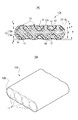
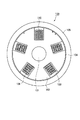
図1に示すように、本実施形態の光ファイバケーブル1は、中心に抗張力体2を有するスペーサ3の溝4に、複数の光ファイバテープ心線10が収容されている。この光ファイバケーブル1は200心型の光ファイバケーブルであり、10本の溝4のそれぞれに、4心の光ファイバテープ心線10が5枚づつ積層されて収容されている。また、10本の溝4は、長尺方向に沿って互いに平行な状態を保ちながら円周方向には交互に反転した螺旋状に形成されている。すなわち、スペーサ3はSZスペーサである。また、溝4の撚りピッチは、500mmである。なお、スペーサ3の外径は、例えば12mmである。
Hereinafter, an example of an embodiment of an optical fiber cable according to the present invention will be described with reference to FIGS.
As shown in FIG. 1, in the
また、光ファイバテープ心線10が溝4から外れるのを防ぐために、スペーサ3の周囲には押さえ巻き5が巻かれている。さらに、押さえ巻き5の外側にはプラスチック製(例えばポリエチレン)のシース6が形成されている。このシース6の外径は、例えば16mmである。
また、抗張力体2は、光ファイバケーブル1に張力が付加された場合に、その張力が光ファイバテープ心線10に直接伝わらないようにするために設けられた抗張力体である。この抗張力体2としては、鋼線が好適に用いられる。
Further, in order to prevent the
The
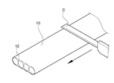
光ファイバケーブル1は、溝4が撚られている方向が周期的に反転しているため、シース6や押さえ巻き5を任意の箇所で除去して、溝4の反転部から光ファイバテープ心線10を容易に取り出すことができる。そのため、SZスペーサを用いた光ファイバケーブル1は、中間後分岐に適した構造である。
Since the direction in which the
ここで、溝4に収容されている光ファイバテープ心線10の態様について説明する。
図2は、光ファイバテープ心線10を示す断面図である。この光ファイバテープ心線10は、複数本(ここでは一例として4本用いている)の光ファイバ11を並列し、これら並列している光ファイバ11の外周の全体にわたり、かつ、光ファイバ11の全長にわたって樹脂である外被12により一体的に覆ったものである。
Here, the aspect of the
FIG. 2 is a sectional view showing the
また、図2には、隣接する光ファイバ同士が全て接触した光ファイバテープ心線を示したが、光ファイバ同士が接触せず離れているものであってもよい。ここで、接触していないとは光ファイバテープ心線に含まれる少なくとも2本の光ファイバが接触していないことをいう。光ファイバテープ心線に含まれる光ファイバ同士が接触している場合と接触していない場合とを比較すると、接触している方が光ファイバテープ心線を分岐することが容易である。光ファイバ同士が接触していると、外被を形成する光ファイバ間の樹脂が連続していない箇所をきっかけとして、例えば樹脂をブラシで擦るだけで光ファイバ間の樹脂を破壊させることができ、複数の光ファイバを一体化している樹脂を光ファイバから除去することができる。 2 shows the optical fiber ribbon in which all the adjacent optical fibers are in contact with each other, the optical fibers may not be in contact with each other and may be separated from each other. Here, “not in contact” means that at least two optical fibers included in the optical fiber ribbon are not in contact. Comparing the case where the optical fibers included in the optical fiber ribbon are in contact with the case where they are not in contact, it is easier to branch the optical fiber ribbon when they are in contact. When the optical fibers are in contact with each other, the resin between the optical fibers can be destroyed just by rubbing the resin with a brush, for example, where the resin between the optical fibers forming the jacket is not continuous, The resin in which a plurality of optical fibers are integrated can be removed from the optical fiber.
光ファイバ心線同士が接触しない場合には、光ファイバ心線の間隔が10μm以下であることが好ましい。間隔が10μm以下であれば、外被を形成する樹脂が光ファイバの間に入る量が多くないので、樹脂の破壊が起こりやすく、樹脂が光ファイバ間で連続していない場合とほぼ同程度の外被の除去性が得られ、分岐が容易である。 When the optical fiber cores are not in contact with each other, the interval between the optical fiber cores is preferably 10 μm or less. If the distance is 10 μm or less, the amount of resin forming the outer sheath is not large between the optical fibers, so that the resin is likely to break down, which is almost the same as when the resin is not continuous between the optical fibers. The coat can be removed and branching is easy.
また、この光ファイバテープ心線10は、光ファイバ11が全長にわたって樹脂の外被12によって覆われているため、任意の箇所で外被12を破壊または除去して、どの箇所からでも容易に単心に分岐できる構造である。
In addition, since the
また、光ファイバ11は、コア13aとクラッド13bからなるガラスファイバ13と、このガラスファイバ13の外周を一次保護被覆14で覆い、さらに、保護被覆14の外周を二次保護被覆15により被覆した構成となっている。また、二次保護被覆15の外周に厚さ1μmから10μm程度の着色層が形成されていても良い。また、ガラスファイバ13の周囲に薄膜状のカーボン層がコーティングされていても良い。なお、光ファイバ11は、ITU−T(International Telecommunication Union - Telecommunication standardization sector : 国際電気通信連合・電気通信標準化部門)により定められたG652に準拠するものであることが好ましい。
本発明に適用可能なガラスファイバ13としては、コアと複数層のクラッドからなるガラスファイバ等、いかなる屈折率分布を有するガラスファイバも適用可能である。
The
As the
また、ガラスファイバ13としては、波長1.55μmにおけるPetermann−Iの定義によるモードフィールド径(MFD:Mode Field Diameter)が10μm以下であることが好ましい。さらに、モードフィールド径が8μm以下であるとより好ましい。
モードフィールド径を小さくすると、マイクロベンド損失や曲げ損失(マクロベンド損失)を小さくすることができる。したがって、溝内で光ファイバテープ心線10が受ける外力による、伝送損失の増加を抑えることができる。また、小さい曲げ半径で光ファイバ11を曲げても伝送損失の増加が少ないため、活線分岐しやすい。
Moreover, as the
When the mode field diameter is reduced, microbend loss and bending loss (macrobend loss) can be reduced. Therefore, an increase in transmission loss due to an external force received by the
この光ファイバテープ心線10では、並列した4本の光ファイバ11の外周に形成された外被12として、紫外線硬化樹脂を用いている。紫外線硬化型樹脂以外の外被12としては、熱可塑性樹脂、熱硬化性樹脂等も使用することができる。
本実施形態の光ファイバテープ心線10は、外被12の厚さが従来用いられていた光ファイバテープ心線より薄く形成されている。なお、外被12の厚さtは、光ファイバテープ心線10の厚さの最大値をT(μm)、光ファイバ11の外径をd(μm)としたときに、t=(T−d)/2で求めることができ、光ファイバテープ心線10は、T≦d+40(μm)となるように、すなわち、外被12の厚さtが20μm以下となるように外被12の厚さが設定されている。
外被12が薄い光ファイバテープ心線10を用いると、従来のSZスペーサの光ファイバケーブルが有していた高い収納密度と機械特性を確保しつつ、中間部からの光ファイバテープ心線の取り出しが極めて容易な光ファイバケーブル1を低コストで得ることができる。
In the
The
When the optical fiber
このように、光ファイバテープ心線10は、外被12の厚さtが薄いため、作業者による手作業、あるいは、分岐工具により、外被12に亀裂や剥がれを発生させて外被12を容易に剥がし始めることができる。そのため、光ファイバテープ心線10から外被12を剥がして光ファイバ11を分岐させやすい。すなわち、光ファイバテープ心線10は、中間後分岐作業がしやすい構造となっている。
Thus, since the thickness t of the
上述の中間後分岐について、分岐方法の一例を説明する。図3(A)に示すように、光ファイバテープ心線10を、分岐工具60の上ベース61および下ベース62で挟み、これらの上下ベース61,62に立設した線材63を光ファイバテープ心線10の外被12に近づけていく。図3(B)はそのときの断面図を示している。さらに、分岐工具60を光ファイバテープ心線10に押し付けると、図3(C)に示すように、線材63は撓み、この撓んだ線材63の先端の角が光ファイバテープ心線10の外被12と強く接触する。
An example of a branching method for the above-described intermediate post-branching will be described. As shown in FIG. 3A, the optical fiber
分岐工具60を押し付けた状態で、分岐工具60を光ファイバテープ心線10の長手方向(図3(C)でみて左右方向)へ相対的に移動させ、つまり、分岐工具60で光ファイバテープ心線10をこすると、線材63の先端で外被12に傷を付けたり剥いだりして光ファイバ11を分岐する。その際、分岐工具60、光ファイバテープ心線10のいずれか、或いは、両方を移動させてもよい。
With the
線材63は、可撓性を有するため、光ファイバテープ心線10の外被12に押し当てたときに、線材63が反って、線材63の先端の角が外被12にあたる。この状態で、分岐工具60または光ファイバテープ心線10を動かすと線材63(可撓性部材)が外被12に傷を与えたり、あるいは、外被12を剥がしたりする。分岐工具60で光ファイバテープ心線10をこすることを繰り返していくと、光ファイバ11と外被12との界面に剥離が発生する。さらにこの作業を繰り返すと、光ファイバ11の中心軸の上部あるいは下部の外被12が削れ、亀裂が発生し、その後、外被12に亀裂が進展して、外被12が剥がれる。
このようにして光ファイバテープ心線10の外被12が破壊され、各光ファイバに分岐される。
Since the
In this way, the
可撓性の線材63を光ファイバテープ心線に押し付ける力を調整すれば、分岐時の光信号の伝送損失変動量が1.0以下、分岐作業の仕方によっては0.5dB以下となり、活線を含む光ファイバテープ心線であっても、当該活線の光伝送を遮断させることなく分岐することができる。
If the force for pressing the
ここで、外被12の厚さtの違いによる中間後分岐の作業性とそのときの活線ロス増の関係を表1に示す。また、表1には、光ファイバケーブル1中に、すなわちSZスペーサに収容された状態での偏波モード分散(SZケーブルPMD)と、光ファイバの一体化の強度を示す分離試験の結果を示している。なお、表1に示す光ファイバテープ心線の光ファイバの外径dは250μmである。また、外被12を構成する樹脂のヤング率は900MPaである。
Here, Table 1 shows the relationship between the workability of the intermediate post-branch due to the difference in the thickness t of the

なお、表1に示す外被の厚さt=0.0の光ファイバテープ心線とは、樹脂が全ての光ファイバの全体を覆っていないものである。そのような光ファイバテープ心線の一例を図4に示す。
図4に示す光ファイバテープ心線10aは、隣接する光ファイバ11が、全長にわたって樹脂12aによって一体化されている。この樹脂12aは、光ファイバ11の間の窪みを埋めるように形成されており、隣接する光ファイバ11同士を接着している。また、光ファイバテープ心線10aの厚さが、光ファイバ11の外径dより大きくならないように図られている。そのため、この場合の光ファイバテープ心線10aの厚さTは、光ファイバ11の外径dと等しくなっている。
In addition, the optical fiber tape core wire of the jacket thickness t = 0.0 shown in Table 1 is one in which the resin does not cover the entire optical fiber. An example of such an optical fiber ribbon is shown in FIG.
In an
表1に示す中間後分岐性とは、光ファイバテープ心線の中間部分を各光ファイバに分岐するときに、伝送損失の増加が1.0dB以下として分岐することの容易さを示している。本明細書中における評価基準としては、◎は平均2分以内に分岐できることを示し、○は平均2分を超え3分以内に分岐できることを示し、△は平均3分を超え5分以内に分岐できることを示す。また、×は平均5分を超える分岐作業時間がかかってしまうことを示す。
なお、分岐時の伝送損失の増加が1.0dB以下ということは活線分岐できるということである。
The intermediate post-branch property shown in Table 1 indicates the ease of branching when the intermediate portion of the optical fiber ribbon is branched to each optical fiber with an increase in transmission loss of 1.0 dB or less. As evaluation criteria in this specification, ◎ indicates that it can branch within an average of 2 minutes, ○ indicates that it can branch over an average of over 2 minutes and within 3 minutes, and △ indicates a branch over of an average of over 3 minutes and within 5 minutes Show what you can do. Moreover, x shows that it takes a branch work time exceeding 5 minutes on average.
Note that an increase in transmission loss at the time of branching of 1.0 dB or less means that the hot line can be branched.
ここで、中間後分岐性の試験について説明する。
まず、図5(A)に示すように、光ファイバテープ心線10を例えば1m程度の長さだけ外被を残し、その一方側で1番心の光ファイバ11aに波長1.55μmの光を入射するための光源20を接続し、他方側の光ファイバ11aに受光器21とストレージオシロスコープ22を接続する。この状態で、光源20から1番心の光ファイバ11aに波長1.55μmの光を入射する。入射された光は、光ファイバ11aの他方側へ伝わり、受光器21により受光される。受光された光は、ストレージオシロスコープ22によりその受光量が適時観察される。
Here, the intermediate post-branching test will be described.
First, as shown in FIG. 5 (A), the optical fiber
そして、光源20からの光の入射を行っている状態で、図5(B)に示すように、光ファイバテープ心線10を中間後分岐する。すなわち、1番心の光ファイバ11aが活線の状態で光ファイバテープ心線10を単心に分岐する(活線分岐)。このとき、中間後分岐による伝送損失の増加量がストレージオシロスコープ22により計測される。
なお、中間後分岐する長さは、50cmとした。また、中間後分岐する方法は、図3を参照して説明した上記の手順によるものである。
Then, in the state where the light from the
The length of branching after the middle was 50 cm. The method of branching after the intermediate is based on the above procedure described with reference to FIG.
表1に示す光ファイバテープ心線のうち、中間後分岐性が◎,○または△となっているものは、テープ厚さTが290μm以下のもの、すなわちT≦d+40(μm)のものである。これらは、いずれも分岐時の伝送損失の増加を1.0dB以下として5分間以内に中間後分岐可能である。つまり、5分以内に活線分岐可能である。
これに対して、テープ厚さTが光ファイバの外径dより40μmを超える、従来用いられていた外被の厚い光ファイバテープ心線は、中間後分岐性が×であり、分岐時の伝送損失の増加分が1.0dBを超えるか、分岐できたとしても5分を超える所要時間を必要とするものであり、現実的に活線分岐できなかった。
Of the optical fiber ribbons shown in Table 1, those having an intermediate post-branch property of ◎, ○ or Δ are those having a tape thickness T of 290 μm or less, that is, T ≦ d + 40 (μm). . Both of these can be branched after an intermediate period within 5 minutes with an increase in transmission loss at the time of branching of 1.0 dB or less. That is, the hot line can be branched within 5 minutes.
On the other hand, the optical fiber tape core wire having a thick outer sheath, which has been used in the past and whose tape thickness T exceeds 40 μm from the outer diameter d of the optical fiber, has an intermediate post-branch property x, and transmission at the time of branching Even if the increase in loss exceeds 1.0 dB or can be branched, the time required for more than 5 minutes is required, and it was not possible to branch the hot line in practice.
表1に示す活線ロス増は、中間後分岐の作業中に発生する伝送損失の増加量である。本明細書中における評価基準としては、◎は分岐作業中に伝送損失が0.1dBを超えて増加しないことを示し、○は分岐作業中に伝送損失が0.5dBを超えて増加しないことを示し、△は分岐作業中に伝送損失が1.0dBを超えて増加しないことを示す。また、×は分岐作業中に伝送損失の増加値が1.0dBを超えてしまうことを示す。 The hot line loss increase shown in Table 1 is an increase in transmission loss that occurs during the work of intermediate post-branching. As evaluation criteria in this specification, ◎ indicates that the transmission loss does not increase by more than 0.1 dB during the branching operation, and ○ indicates that the transmission loss does not increase by more than 0.5 dB during the branching operation. And Δ indicates that the transmission loss does not increase beyond 1.0 dB during the branching operation. Further, x indicates that the increase value of the transmission loss exceeds 1.0 dB during the branching operation.
表1に示す光ファイバテープ心線のうち、活線ロス増が○または△となっているものは、テープ厚さTが290μm以下のもの、すなわちT≦d+40(μm)のものである。これらは、いずれも分岐時の伝送損失の増加を1.0dB以下として活線の光ファイバテープ心線を中間後分岐することが可能である。このうち、テープ厚さTが275μm以下のもの、すなわちT≦d+25(μm)のものは、活線ロス増が○となっており、伝送損失の増加がさらに低く抑えられ、より好ましい。
これに対して、テープ厚さTが光ファイバの外径dより40μmを超える、従来用いられていた外被の厚い光ファイバテープ心線は、活線ロス増が×であり、分岐作業中に伝送損失の増加値が1.0dBを超えてしまう。
Of the optical fiber ribbons shown in Table 1, those having a hot wire loss increase of ◯ or Δ are those having a tape thickness T of 290 μm or less, that is, T ≦ d + 40 (μm). In both cases, the increase in transmission loss at the time of branching is 1.0 dB or less, and the optical fiber ribbon of the live line can be branched after the middle. Of these, tapes having a tape thickness T of 275 μm or less, that is, T ≦ d + 25 (μm), are more preferable because the increase in the live line loss is ○ and the increase in transmission loss is further suppressed.
On the other hand, the optical fiber tape core wire having a thick outer sheath that has been used in the past and whose tape thickness T exceeds 40 μm from the outer diameter d of the optical fiber has an increase in hot wire loss, and during the branching operation The increase value of the transmission loss exceeds 1.0 dB.
表1に示すSZケーブルPMDは、図1に示したように、光ファイバテープ心線10が溝4に収容された状態でのリンク偏波モード分散である。ここで、リンク偏波モード分散とは、光ファイバケーブル1に収容された全ての光ファイバ11の偏波モード分散(PMD)の値を統計的に処理して、同等の光ファイバケーブルを多数条直列に接続した時に発生し得るPMDの最大値を示したものである。ここでは、その統計的な処理を、中心極限定理に基づいて行っている。なお、PMDの測定は、光ファイバケーブル1の長さが1000m以上の条件で行い、干渉法による測定器(サンテック製6000B)を用いた。
The SZ cable PMD shown in Table 1 is the link polarization mode dispersion in a state where the
本明細書中における評価基準としては、◎はリンク偏波モード分散(リンクPMD)が0.05(ps/km1/2)以下であり、〇は0.05(ps/km1/2)を超えて0.1(ps/km1/2)以下であり、△は0.1(ps/km1/2)を超えて0.2(ps/km1/2)以下である場合を示す。また、×は、リンク偏波モード分散が0.2(ps/km1/2)を超えてしまう場合を示す。 As evaluation criteria in this specification, ◎ indicates that the link polarization mode dispersion (link PMD) is 0.05 (ps / km 1/2 ) or less, and ○ indicates 0.05 (ps / km 1/2 ). And 0.1 (ps / km 1/2 ) or less, and Δ is 0.1 (ps / km 1/2 ) and 0.2 (ps / km 1/2 ) or less. Show. Further, x indicates a case where the link polarization mode dispersion exceeds 0.2 (ps / km 1/2 ).
テープスロット型の光ファイバケーブルでは、溝に光ファイバテープ心線が積層されて配置されているため、一定方向からの応力が発生して光ファイバに複屈折が生じる上に、光ファイバテープ心線の外被の硬化収縮によっても複屈折が生じやすい。光ファイバテープ心線の外被(樹脂)は、その製造時の硬化により、5%程度収縮する。この硬化収縮によって光ファイバに外力がかかり、光ファイバ内に応力が発生するが、その応力は、光ファイバテープ心線の断面形状が幅方向に広いために、幅方向と厚さ方向とで異なってしまう。特に、光ファイバに対して光ファイバテープ心線の厚さ方向の外被は、光ファイバテープ心線の幅方向に連続しているために、この部分の外被が厚くなっていると、幅方向に発生する応力が大きくなり、幅方向と厚さ方向とで発生する応力差が大きくなってしまう。 In a tape slot type optical fiber cable, optical fiber tape cores are laminated in the groove, so that stress from a certain direction is generated and birefringence occurs in the optical fiber. Birefringence is also likely to occur due to curing shrinkage of the outer casing. The outer sheath (resin) of the optical fiber ribbon is shrunk by about 5% due to curing during its manufacture. Due to this curing shrinkage, an external force is applied to the optical fiber, and a stress is generated in the optical fiber. The stress differs in the width direction and the thickness direction because the cross-sectional shape of the optical fiber ribbon is wide in the width direction. End up. In particular, the outer sheath in the thickness direction of the optical fiber ribbon with respect to the optical fiber is continuous in the width direction of the optical fiber ribbon. The stress generated in the direction increases, and the stress difference generated between the width direction and the thickness direction increases.
このように、テープスロット型の光ファイバケーブルではPMDが高くなりやすい。特に、SZスペーサの光ファイバケーブルの場合には、その反転する溝形状により、光ファイバが複雑に曲げられてしまうため、PMDが高くなりやすい傾向がある。 Thus, PMD tends to be high in a tape slot type optical fiber cable. In particular, in the case of an optical fiber cable with SZ spacers, the PMD tends to be high because the optical fiber is bent in a complicated manner due to the inverted groove shape.
本実施形態では、従来よりも外被の薄い光ファイバテープ心線を用いているため、硬化収縮に起因して発生する複屈折は極めて小さく抑えられる。したがって、本実施形態の光ファイバケーブルは、PMDを低く抑えることが可能となっている。
表1に示す光ファイバテープ心線のうち、T≦d+25(μm)の場合に、SZケーブルPMDが○となり、特に良好であることがわかる。
In this embodiment, since the optical fiber tape core wire having a thinner jacket than that of the conventional one is used, birefringence generated due to curing shrinkage can be suppressed to be extremely small. Therefore, the optical fiber cable of the present embodiment can keep PMD low.
Among the optical fiber ribbons shown in Table 1, when T ≦ d + 25 (μm), the SZ cable PMD becomes ◯, and it can be seen that it is particularly good.
表1に示すファイバ分離の有無は、光ファイバの一体化の強度を示す分離試験による結果を示すものである。
この分離試験は、図6に示すように、試験対象である光ファイバテープ心線10が巻かれた繰り出しボビン24から、巻き取りボビン25に巻き替えを行い、そのパスラインの途中で光ファイバテープ心線10に外力を与えるようになっている。光ファイバテープ心線10に与える外力は、ダンサローラと重りから構成される荷重負荷部26によって、光ファイバテープ心線10に一定の張力を与えるとともに、直径3mmの丸棒27を2本用いて小径の曲げを逆向きに与えることにより発生させる。
The presence / absence of fiber separation shown in Table 1 indicates the result of a separation test indicating the strength of integration of optical fibers.
In this separation test, as shown in FIG. 6, the winding
本明細書中におけるファイバ分離の評価基準としては、〇は光ファイバと外被(樹脂)との分離がなく、光ファイバテープ心線が長手方向にわたって一体化されたままであった場合を示し、×は光ファイバと外被(樹脂)との分離箇所が発生した場合を示す。 As an evaluation standard for fiber separation in this specification, ◯ indicates a case where there is no separation between the optical fiber and the jacket (resin), and the optical fiber tape core wire remains integrated in the longitudinal direction. Indicates a case where a separation point between the optical fiber and the jacket (resin) occurs.
表1に示す光ファイバテープ心線のうち、T≧d+1(μm)である場合に、光ファイバテープ心線の分離が発生せず、良好であった。すなわち、外被の厚さtが0.5μm以上であれば、各光ファイバを一体化させておくのに十分な強度が得られることがわかった。
表1に示す光ファイバテープ心線のうち、T=dのもの(図4参照)は、この分離試験において分離箇所が発生しているが、光ファイバケーブルを製造する際のライン中で光ファイバテープ心線にかかるしごき等の外力が軽減されるように配慮することで、そのケーブル化の製造工程で心線の分離が発生してしまうような不具合を防止することができる。そして、このT=dである光ファイバテープ心線は、各光ファイバの中心を通る光ファイバテープ心線の厚さ方向の箇所で実質的に外被が途切れているため、各光ファイバが光ファイバテープ心線の幅方向に分離しやすく、各光ファイバの全体を外被が覆う形状の光ファイバテープ心線に比べて、中間後分岐性が良好である。
Of the optical fiber ribbons shown in Table 1, when T ≧ d + 1 (μm), separation of the optical fiber ribbons did not occur, which was good. That is, it has been found that when the thickness t of the jacket is 0.5 μm or more, sufficient strength can be obtained to keep the optical fibers integrated.
Of the optical fiber ribbons shown in Table 1, those with T = d (see FIG. 4) have separation points in this separation test, but the optical fiber is in the line when manufacturing the optical fiber cable. By taking into consideration that the external force such as ironing applied to the tape core is reduced, it is possible to prevent a problem that the core is separated in the cable manufacturing process. Since the optical fiber tape core wire with T = d is substantially interrupted in the thickness direction of the optical fiber tape core wire passing through the center of each optical fiber, It is easy to separate in the width direction of the fiber tape core wire, and the intermediate post-branching property is better than the optical fiber tape core wire having a shape that covers the entire optical fiber with the jacket.
なお、図4に示したような樹脂12aが各光ファイバ11の全体を覆っていない光ファイバテープ心線10aは、樹脂12と光ファイバとの接着力だけで各光ファイバ11が一体化されている。これに対して、図2に示したような光ファイバテープ心線10は、樹脂が外被12として各光ファイバ11の全体を一体的に覆っているため、樹脂と光ファイバとの接着力だけでなく、外被12自身がその形状を保持しようとする力によって、光ファイバテープ心線10の全体が一体化された状態を保ちやすい。
Note that the optical fiber
また、上述したような光ファイバテープ心線(図2参照)は、外被(樹脂)12と、光ファイバ11のそれぞれのヤング率Eと断面積Sとの積の和(ES積和)の比を、適切な値となるように設定することで、PMDを低減させることができる。外被12が硬化収縮を起こす際に光ファイバ11に作用する応力の大きさは、外被12を構成する樹脂のヤング率が大きいほど、また外被12の厚さが厚いほど、大きくなる。ここで、PMDが増大する原因となるのは、光ファイバ11のガラスファイバ13に発生する歪みである。この歪みの大きさは、一次保護被覆14と、二次保護被覆15と、着色層とを含む被覆層を通してガラスファイバ13まで到達する力の大きさ、及びガラスファイバ13のヤング率によって決まる。
Further, the optical fiber tape core wire (see FIG. 2) as described above is the sum of the products (ES product sum) of the outer sheath (resin) 12 and the respective Young's modulus E and cross-sectional area S of the
そこで、外被12のヤング率が、700MPa、900MPa、1200MPa、1500MPaである各条件において、光ファイバテープ心線10の厚さTが異なる場合、すなわち外被12の厚さが異なる場合の、光ファイバ11に対する外被12のES積比と、SZケーブルPMDとの関係を調べた。
Therefore, in each condition where the Young's modulus of the
なお、ガラスファイバ13は、ヤング率が73000MPaであり、外径が125μmである。一次保護被覆14は、ヤング率が1MPaであり、外径が200μmである。二次保護被覆15は、ヤング率が700MPaであり、外径は240μmである。着色層は、ヤング率が1500MPaであり、外径は250μmである。
The
本明細書中では、ES積の比は、1心の光ファイバあたりに関するES積を正確に求めるために、光ファイバテープ心線10の厚さが一定である領域において計算している。すなわち、光ファイバテープ心線10の横断面内における、隣接する2本の光ファイバ11の各中心を結ぶ直線に垂直であって、かつその2本の光ファイバ11の各中心をそれぞれ通る2本の直線(例えば図2に示す破線X,Y)で区画される内側の領域で、光ファイバ11のES積の和及び外被12のES積を算出し、各条件において比較している。
In the present specification, the ratio of the ES product is calculated in a region where the thickness of the
外被12のヤング率が700MPaである場合のES積比とSZケーブルPMDとの関係を表2に示す。
外被12のヤング率が900MPaである場合のES積比とSZケーブルPMDとの関係を表3に示す。
外被12のヤング率が1200MPaである場合のES積比とSZケーブルPMDとの関係を表4に示す。
外被12のヤング率が1500MPaである場合のES積比とSZケーブルPMDとの関係を表5に示す。
ここで、表2から表5に示すファイバES積は、ガラスファイバ13と、一次保護被覆14と、二次保護被覆15と、着色層とから構成される領域のそれぞれのES積の和であり、樹脂ES積は、外被12のES積である。ES積比は、「樹脂ES積/ファイバES積和」により表される。
Here, the fiber ES products shown in Tables 2 to 5 are the sum of the ES products of the regions composed of the
表2から表5に示すように、SZケーブルPMDが○あるいは△となる条件、すなわち、SZスペーサの光ファイバケーブルに収容された光ファイバ全心のリンクPMDが0.2(ps/km1/2)以下となる条件は、ES積比が0.026以下となる場合である。また、SZケーブルPMDが○となる条件、すなわちリンクPMDが0.1(ps/km1/2)以下となる条件は、ES積比が0.020以下となる場合である。
このように、光ファイバ11に対する外被12のES積比を所望の値となるように設定することにより、光ファイバ11のPMDを低く抑えることができる。
As shown in Tables 2 to 5, the conditions under which the SZ cable PMD is ○ or Δ, that is, the link PMD of the entire optical fiber accommodated in the optical fiber cable of the SZ spacer is 0.2 (ps / km 1 / 2 ) The condition that is equal to or less is the case where the ES product ratio is 0.026 or less. Further, the condition that the SZ cable PMD is ◯, that is, the condition that the link PMD is 0.1 (ps / km 1/2 ) or less is a case where the ES product ratio is 0.020 or less.
Thus, the PMD of the
次に、本実施形態の光ファイバケーブルに収容される光ファイバテープ心線の他の好適な態様について説明する。
図7(A)は、その光ファイバテープ心線の断面図であり、(B)は斜視図である。
図7に示すように、光ファイバテープ心線10bは、光ファイバ11を覆っている外被12bにおいて、隣り合う光ファイバ11、11の間に形成された窪みに応じて、外被の凹部16が形成されている。この凹部16は、その窪みが最も大きい部分として底部17が形成されている。
Next, another preferred aspect of the optical fiber ribbon housed in the optical fiber cable of this embodiment will be described.
FIG. 7A is a cross-sectional view of the optical fiber ribbon, and FIG. 7B is a perspective view.
As shown in FIG. 7, the
上述したように、光ファイバ11の周囲に形成される外被の厚さは、PMDを低減させる観点によると薄いほうが好ましく、0.5μm程度の厚さがあれば良い。しかし、実際にそのような光ファイバテープ心線を製造する場合には、ある程度の厚さがあったほうが好ましい。その理由としては、外被となる樹脂の厚さを薄く形成しようとすると、部分的に樹脂が塗布されない(これを樹脂切れと呼ぶ)おそれが生じる。そのため、光ファイバ11に対して2.5μm以上の厚さで外被を形成することが望ましい。その場合、所望の外被の厚さを保ちながら光ファイバテープ心線の厚さ方向の樹脂の量を減らすには、隣接する光ファイバ間の窪みに形成される外被を少なくすれば良い。樹脂切れが発生しやすい箇所は、光ファイバの外径が光ファイバテープ心線の厚さ方向に最も大きくなる箇所であるため、隣接する光ファイバ間の樹脂の量を減らすことは、樹脂を確実に塗布することを妨げない。
そのため、図7に示すような凹部16を形成することは、樹脂切れを防止しつつPMDの増大を抑制することができる。
As described above, the thickness of the jacket formed around the
Therefore, forming the
また、外被12bの凹部16は、光ファイバテープ心線10bから外被12bを剥がして光ファイバ11を分岐するときに有効となる。外被12bの厚さが薄い部分が多いほど、外被12bの破壊が起こりやすいため、分岐作業が容易となる。また、分岐作業が容易化するため、分岐作業中に光ファイバに与える外力も小さくて済む。そのため、活線分岐のロス増を小さく抑えることができる。
Further, the
図7に示した光ファイバテープ心線10bは、凹部16の深さYが、外被12bの共通接線S1と各光ファイバ11の共通接線S2との間の距離より短く形成されている。つまり、底部17の位置が各光ファイバ11の共通接線S2よりも外側に位置するように凹部16が形成されている。
In the
また、本実施形態の光ファイバケーブルに収容される光ファイバテープ心線としては、図7に示した光ファイバテープ心線10bの構成を一部変更した他の態様である、図8に示す光ファイバテープ心線10cが挙げられる。
図8(A)は、光ファイバテープ心線10cの断面図であり、(B)は斜視図である。光ファイバテープ心線10cの基本的な構成は図7に示した光ファイバテープ心線10bと同様であり、共通する構成については説明を省略する。
光ファイバ11の外周を覆っている外被12cでは、隣り合う光ファイバ11c間に形成される窪みに応じて、凹部形状となっている。この外被の凹部16cは、図7の場合よりも凹部形状が深くなっている。光ファイバテープ心線10cは、凹部16cの底部17cが、光ファイバ11の共通接線S2cよりも内側に位置するように形成されている。
Further, as the optical fiber tape core wire accommodated in the optical fiber cable of the present embodiment, the optical fiber tape shown in FIG. 8, which is another aspect obtained by partially changing the configuration of the optical fiber
FIG. 8A is a cross-sectional view of the
The
なお、光ファイバテープ心線を図1に示したような溝に収容する場合、光ファイバテープ心線の幅方向の端部に位置する光ファイバとその内側に位置する光ファイバとでは、スペーサの中心からの距離が異なる。そのため、螺旋状に形成された溝内に収容された状態では、端部の光ファイバと内側の光ファイバとの間に溝内での長さの差が生じ、光ファイバに応力が発生する。この応力は、溝内での曲げによる応力とともにガラスファイバに異方性の応力を生じさせるため、複屈折が起こり、PMDが増加する原因となる。 When the optical fiber ribbon is housed in the groove as shown in FIG. 1, the optical fiber located at the end in the width direction of the optical fiber ribbon and the optical fiber located inside the optical fiber are not separated. The distance from the center is different. Therefore, in the state accommodated in the spirally formed groove, a length difference in the groove occurs between the optical fiber at the end and the inner optical fiber, and stress is generated in the optical fiber. This stress causes anisotropic stress in the glass fiber together with the stress caused by bending in the groove, causing birefringence and increasing PMD.
これに対して、図8に示すような光ファイバテープ心線10cは、外被に凹部が形成されているため、図9に示すように、幅方向に撓み易くなっており、光ファイバテープ心線10cを溝に収容した時に、光ファイバテープ心線10cに無理な力がかからず、端部の光ファイバと内側の光ファイバとの間に発生する溝内での長さの差が解消されて、そのケーブルPMDが改善できるものと考えられる。また、光ファイバテープ心線10cの外被12cが光ファイバ11の外周に沿って円形状に近づくため、光ファイバテープ心線11cを製造する際の外被12cの硬化収縮応力の異方性が小さくなり、光ファイバテープ心線10cのケーブル状態でのPMDを改善できるものと考えられる。なお、この効果は、図7に示す光ファイバテープ心線10bにおいても得られるが、凹部がより深く形成された光ファイバテープ心線10cの方がより顕著に得られる。
On the other hand, the optical fiber
ここで、図7及び図8に示すような外被に形成された凹部の深さに関して、複数の光ファイバを並べ、外被により一体化し光ファイバテープ心線として製造する際の光ファイバのばらけの防止や、光ファイバテープ心線の敷設作業時の外被の剥離防止(光ファイバのばらけの原因となる)あるいは良好な分岐作業、活線分岐時の伝送損失の増減等について検討した。その結果、凹部は、隣り合う光ファイバにより形成される共通接線を超えないように、言い換えると共通接線よりも内側に入り込んで形成されるのが好ましいことがわかった。 Here, with respect to the depth of the recess formed in the jacket as shown in FIGS. 7 and 8, a plurality of optical fibers are lined up and integrated with the jacket to produce an optical fiber ribbon. We examined the prevention of peeling, prevention of peeling of the jacket when laying the optical fiber ribbon (causes scattering of the optical fiber), good branching work, increase / decrease of transmission loss when hot-line branching, etc. . As a result, it has been found that the recess is preferably formed so as not to exceed the common tangent formed by the adjacent optical fibers, in other words, to enter the inside of the common tangent.
その具体的な検討結果について、次に説明する。
光ファイバテープ心線の厚さT(μm)が270μm、280μm、290μmである場合において、凹部の深さが異なるときの、凹部の深さY(μm)に対する外被の厚さt(μm)の比t/Yと、光ファイバの外径d(μm)に対する凹部での光ファイバテープ心線の厚さg(μm)の比g/dとを算出し、それぞれの場合の中間後分岐性、活線ロス増、SZケーブルPMDについて調べた。
The specific examination results will be described next.
When the thickness T (μm) of the optical fiber ribbon is 270 μm, 280 μm, and 290 μm, the thickness t (μm) of the jacket with respect to the depth Y (μm) of the recess when the depth of the recess is different The ratio t / Y of the optical fiber and the ratio g / d of the thickness g (μm) of the optical fiber tape core wire at the concave portion to the outer diameter d (μm) of the optical fiber are calculated. Then, the hot wire loss increase and the SZ cable PMD were examined.
光ファイバテープ心線の厚さTが270μmである場合の中間後分岐性、活線ロス増、SZケーブルPMDの関係を表6に示す。なお、表中の比率(T−d)/2Yは、t/Yと同じ値である。
光ファイバテープ心線の厚さTが280μmである場合の中間後分岐性、活線ロス増、SZケーブルPMDの関係を表7に示す。
光ファイバテープ心線の厚さTが290μmである場合の中間後分岐性、活線ロス増、SZケーブルPMDの関係を表8に示す。
表6から表8に示すように、中間後分岐性、活線ロス増、SZケーブルPMDのいずれにおいても、凹部の深さYが大きくなるほど良好な結果が得られた。
また、光ファイバテープ心線の厚さTが270μmまたは280μmである場合、すなわちT≦d+30(μm)である場合には、中間後分岐性及び活線ロス増の結果が特に良好であった。これは、図3に示すような分岐工具を用いた場合に、凹部の効果により、単に外被を薄肉化した光ファイバテープ心線よりも分岐性が良くなることが理由であると考えられる。例えば、表1に示したテープ厚さT=270μmの場合に、中間後分岐性が○であることに対して、表7に示したテープ厚さT=280μmで凹部深さY=5μmの場合に、中間後分岐性が◎であり、凹部の効果を確認できる。
As shown in Tables 6 to 8, in any of the intermediate post-branching property, the hot wire loss increase, and the SZ cable PMD, a better result was obtained as the depth Y of the concave portion was increased.
In addition, when the thickness T of the optical fiber ribbon was 270 μm or 280 μm, that is, when T ≦ d + 30 (μm), the results of intermediate post-branching and increased hot-wire loss were particularly good. This is considered to be because, when a branching tool as shown in FIG. 3 is used, the branching property becomes better than the optical fiber ribbon having a thin outer jacket due to the effect of the recess. For example, when the tape thickness T shown in Table 1 is 270 μm, the intermediate post-branching property is ○, whereas the tape thickness T shown in Table 7 is 280 μm and the recess depth Y is 5 μm. Further, the intermediate post-branching property is ◎, and the effect of the concave portion can be confirmed.
また、中間後分岐性に着目すると、比率(T−d)/2Yの値に特に関係付けられることがわかる。例えば、比率(T−d)/2Yが4.0以下である場合に、中間後分岐性が良好である。
また、SZケーブルPMDに着目すると、比率g/dの値に特に関係付けられることがわかる。例えば、比率g/dが1.0以下である場合、すなわち、底部が光ファイバの共通接線より内側にある場合に、樹脂の量が十分に減少して、PMDの顕著な抑制効果が得られる。
比率g/dが1.0以下であれば、底部が共通接線より外側とならないように外被が薄いため、長さ方向に曲がり易くなっていたり、凹部が深くなっているので、図9に示すような撓みが起こりやすく、ケーブルPMDが効果的に改善できるものと考えられる。
Further, when attention is paid to the intermediate post-branching property, it can be seen that it is particularly related to the ratio (T−d) / 2Y. For example, when the ratio (Td) / 2Y is 4.0 or less, the intermediate post-branching property is good.
Further, when attention is paid to the SZ cable PMD, it can be seen that it is particularly related to the value of the ratio g / d. For example, when the ratio g / d is 1.0 or less, that is, when the bottom is inside the common tangent of the optical fiber, the amount of resin is sufficiently reduced, and a remarkable PMD suppressing effect is obtained. .
If the ratio g / d is 1.0 or less, the outer cover is thin so that the bottom portion does not come outside the common tangent line, so that it is easy to bend in the length direction or the concave portion is deep. It is considered that the bending as shown in the figure tends to occur and the cable PMD can be effectively improved.
さらに、比率g/dが0.8以下である場合、特にスペーサに収容された状態でのPMDがさらに効果的に抑制される。
一般的な光ファイバの被覆は、ヤング率の低い一次保護被覆がガラスファイバの周囲を覆い、その外周が、ヤング率の高い二次保護被覆と着色層が覆っている。また、その一次保護被覆の外径は、光ファイバの外径dの0.8倍程度である。そこで、凹部の樹脂がこの一次保護被覆を超えない範囲にあると、外被が変形しやすくなって図9に示すような撓みが起こりやすい。したがって、PMDをさらに抑制しやすくなる。
Furthermore, when the ratio g / d is 0.8 or less, PMD in the state accommodated in the spacer is further effectively suppressed.
In a general optical fiber coating, a primary protective coating with a low Young's modulus covers the periphery of the glass fiber, and a secondary protective coating with a high Young's modulus and a colored layer cover the outer periphery. Further, the outer diameter of the primary protective coating is about 0.8 times the outer diameter d of the optical fiber. Therefore, when the resin in the recess is in a range not exceeding the primary protective coating, the outer cover is easily deformed, and bending as shown in FIG. 9 is likely to occur. Therefore, it becomes easier to suppress PMD.
図7や図8に示すような、凹部が形成された光ファイバテープ心線において、その凹部は、なめらかな曲線形状Rであることが望ましい。例えば、凹部が光ファイバ心線の形状に沿って底部がとがった形状であると、応力が底部に集中して、割れや亀裂等が発生しやすくなるからである。 In the optical fiber tape core wire in which the concave portion is formed as shown in FIGS. 7 and 8, it is desirable that the concave portion has a smooth curved shape R. For example, if the concave portion has a shape in which the bottom portion is sharp along the shape of the optical fiber core wire, stress concentrates on the bottom portion, and cracks, cracks, and the like are likely to occur.
また、図2、図4、図7、図8に示すような、本発明の光ファイバケーブルに用いられる光ファイバテープ心線においては、光ファイバと外被との密着力は、活線分岐時の伝送損失の増大や分岐作業効率に影響を及ぼすときがある。光ファイバと外被(樹脂)との密着力は、伝送損失の増大防止や分岐作業性を考慮すると、光ファイバ1本あたりの密着力が0.025(gf)〜0.25(gf)の範囲内であることが望ましい。前記密着力が前記範囲よりも小さいとケーブル化時に外被が破壊されて各光ファイバがばらばらになることがある。また、前記密着力が前記範囲より大きいと分岐性が悪くなる。 Further, in the optical fiber ribbon used in the optical fiber cable of the present invention as shown in FIGS. 2, 4, 7, and 8, the adhesion between the optical fiber and the jacket is determined when the live line is branched. There are times when the increase in transmission loss and the branching work efficiency are affected. The adhesive strength between the optical fiber and the outer sheath (resin) is 0.025 (gf) to 0.25 (gf) per optical fiber in consideration of prevention of increase in transmission loss and branching workability. It is desirable to be within the range. If the adhesion force is smaller than the above range, the outer sheath may be broken during cable formation, and the optical fibers may be separated. Moreover, when the said adhesive force is larger than the said range, branching property will worsen.
光ファイバと外被との密着力は、例えば以下の方法で測定することができる。
図10に示すように光ファイバテープ心線10にカッターナイフの刃Cを当ててガラスまで切り込む。刃を長さ方向にテープ心線の端部へ移動させてテープ心線の片面の樹脂を剥ぎ取る。光ファイバテープ心線10の端部の外被12を約30mm手で剥いで折り返す。
そして、図11に示すように、外被12が剥がれた光ファイバ11を下チャック50Lで掴み、折り返した外被12の先端を上チャック50Uで掴む。上下チャック50L、50U間の距離は約40mmとする。上チャック50Uと下チャック50Lを相対的に180度をなす方向に200mm/分の速度で約50mm移動させ、外被12を剥離させる。
測定値の極大値および極小値をそれぞれ最大値とその次点の値、最小値とその次点の値、合計4点取り、その平均値を求め、さらに光ファイバテープ心線に含まれる光ファイバの心数で割った値を心線あたりの密着力とする。
The adhesion force between the optical fiber and the jacket can be measured, for example, by the following method.
As shown in FIG. 10, the blade C of the cutter knife is applied to the
Then, as shown in FIG. 11, the
The maximum value and minimum value of the measured values are taken as the maximum value and its next point value, the minimum value and its next point value, a total of 4 points, the average value is obtained, and the average value of the optical fiber contained in the optical fiber ribbon is obtained. The value divided by the number of hearts is taken as the adhesion per core.
本発明において用いられる光ファイバテープ心線では、光ファイバがばらけないで一体性を維持することを主たる目的とした場合は、外被の厚みは0.5μm以上が好ましく、この場合の光ファイバテープ心線の最大厚さTは、T≧光ファイバの外径d+1(μm)となる。 In the optical fiber ribbon used in the present invention, when the main purpose is to maintain the integrity of the optical fiber without scattering, the thickness of the jacket is preferably 0.5 μm or more, and the optical fiber in this case The maximum thickness T of the tape core wire satisfies T ≧ optical fiber outer diameter d + 1 (μm).
また、光ファイバテープ心線の外被の物性によっても、活線分岐時の伝送損失の増大や分岐作業効率に影響を及ぼすときがある。外被の材料の特性として、降伏点応力が20MPa〜45MPaの範囲内が望ましく、容易に分岐作業を行うことができたり、活線分岐時の伝送損失を抑制することができる。降伏点応力はJIS K7113に従い、2号試験片について引っ張り速度を50mm/分として測定する。降伏点応力が20MPa未満であると光ファイバテープ心線を集合してケーブル化する工程で加わる外力によって各光ファイバが分離してしまい、ケーブル化できないことがある。降伏点応力が45MPaを超えると、外被が破壊されにくく光ファイバテープ心線の中間後分岐がしづらい。 In addition, the physical properties of the outer sheath of the optical fiber ribbon may affect the increase in transmission loss at the time of hot line branching and branching efficiency. As a characteristic of the material of the jacket, the yield point stress is desirably in the range of 20 MPa to 45 MPa, and branching can be easily performed, or transmission loss at the time of hot line branching can be suppressed. The yield point stress is measured in accordance with JIS K7113 with a No. 2 test piece at a pulling speed of 50 mm / min. If the yield point stress is less than 20 MPa, the optical fibers may be separated by an external force applied in the process of gathering the optical fiber ribbons into a cable, and may not be cabled. If the yield point stress exceeds 45 MPa, the outer sheath is difficult to break, and it is difficult to branch the optical fiber ribbon in the middle.
また、ここで、図1に示した光ファイバケーブル1について、波長1.55μmにおける伝送損失値と偏波モード分散(PMD)値を測定した。また、中間後分岐時の伝送損失の増加量を測定した。
なお、ここで用いた光ファイバテープ心線は、図8に示した光ファイバテープ心線10cであり、その厚さTは260μmである。光ファイバ11の外径dは250μmである。また、外被の厚さtは5μmであり、凹部の深さYは30μmであり、凹部での光ファイバテープ心線の厚さgは200μmである。ただし、光ファイバテープ心線として一体化された光ファイバのうち、100心をG652に準拠するものを用いて、残りの100心をモードフィールド径が10μm以下のものを用いた。
Here, the transmission loss value and the polarization mode dispersion (PMD) value at a wavelength of 1.55 μm were measured for the
The optical fiber ribbon used here is the
光ファイバケーブル1に収容された状態での光ファイバの伝送損失値は、G652の光ファイバで、最大値が0.23dB/kmであり、平均値が0.21dB/kmであった。モードフィールド径が10μm以下の光ファイバでは、最大値が0.21dB/kmであり、平均値が0.20dB/kmであった。
また、偏波モード分散値は、G652の光ファイバで、平均値が0.025(ps/km1/2)であり、標準偏差が0.020(ps/km1/2)であり、リンクPMDは0.046(ps/km1/2)であった。モードフィールド径が10μm以下の光ファイバでは、平均値が0.022(ps/km1/2)であり、標準偏差が0.018(ps/km1/2)であり、リンクPMDは0.042(ps/km1/2)であった。
このように、ケーブル化した後の光ファイバの伝送損失及びPMDは、モードフィールド径が10μm以下のものが、特に特性が良好であった。
The transmission loss value of the optical fiber in the state accommodated in the
The polarization mode dispersion value is G652 optical fiber, the average value is 0.025 (ps / km 1/2 ), the standard deviation is 0.020 (ps / km 1/2 ), and the link The PMD was 0.046 (ps / km 1/2 ). In an optical fiber having a mode field diameter of 10 μm or less, the average value is 0.022 (ps / km 1/2 ), the standard deviation is 0.018 (ps / km 1/2 ), and the link PMD is 0.00. 042 (ps / km 1/2 ).
As described above, the transmission loss and PMD of the optical fiber after being cabled were particularly good when the mode field diameter was 10 μm or less.
また、上述したように、SZスペーサを用いた光ファイバケーブルは、中間後分岐性が良好である。そのため、局から一般の加入者までを繋ぐ、加入者系の通信路に用いられることが多い。そのため、SZスペーサの光ファイバケーブルの長さは局同士を繋ぐ中継系のものに比べて短い場合が多く、長くても数十kmである。ただし、1つの加入者に対して局から加入者までの1本の光ファイバを割り当てると、加入者数が多い場合に収容心数の多い光ファイバケーブルが必要となり、太径化してしまうため、例えば管路へ敷設する際に好ましくない。このため、1本の光ファイバに多数の加入者の信号を重複させる波長多重伝送(WDM)技術が有効であり、高速伝送可能な光ファイバケーブルが望まれる。
本発明に係る光ファイバケーブルのように、リンクPMDが0.2(ps/km1/2)以下であると、伝送可能距離は、伝送速度が40Gbpsの場合に156kmとなり、加入者系への十分な通信量を得ることが可能となる。
また、リンクPMDが0.1(ps/km1/2)以下であると、伝送可能距離は、伝送速度が40Gbpsの場合に625km、伝送速度が80Gbpsの場合に156kmとなり、より好ましい。
Further, as described above, the optical fiber cable using the SZ spacer has good intermediate post-branching properties. For this reason, it is often used for a subscriber communication channel that connects a station to a general subscriber. For this reason, the length of the optical fiber cable of the SZ spacer is often shorter than that of the relay system connecting stations, and is several tens of kilometers at the longest. However, if one optical fiber from the station to the subscriber is assigned to one subscriber, an optical fiber cable having a large number of accommodating cores is required when the number of subscribers is large, and the diameter is increased. For example, it is not preferable when laying in a pipeline. For this reason, a wavelength division multiplexing (WDM) technique for overlapping a number of subscriber signals on one optical fiber is effective, and an optical fiber cable capable of high-speed transmission is desired.
When the link PMD is 0.2 (ps / km 1/2 ) or less as in the optical fiber cable according to the present invention, the transmittable distance is 156 km when the transmission speed is 40 Gbps, and A sufficient communication amount can be obtained.
Further, when the link PMD is 0.1 (ps / km 1/2 ) or less, the transmittable distance is 625 km when the transmission speed is 40 Gbps, and 156 km when the transmission speed is 80 Gbps, which is more preferable.
ここで、光ファイバケーブルから中間後分岐して伝送損失を測定する方法について、図12を参照して説明する。
まず、図12に示すように、光ファイバケーブル1の一方側で、任意の光ファイバテープ心線のうち、1番心の光ファイバ11aに波長1.55μmの光を入射するための光源20を接続し、他方側の光ファイバ11aに受光器21とストレージオシロスコープ22を接続する。この状態で、光源20から1番心の光ファイバ11aに波長1.55μmの光を入射する。入射された光は、光ファイバ11aの他方側へ伝わり、受光器21により受光される。受光された光は、ストレージオシロスコープ22によりその受光量が適時観察される。
Here, a method for measuring the transmission loss by branching from the optical fiber cable in the middle will be described with reference to FIG.
First, as shown in FIG. 12, on one side of the
そして、光源20からの光の入射を行っている状態で、光ファイバケーブル1の中間部で500mm程度の長さでシースと押さえ巻きを除去し、スペーサ3を捻りながら曲げて、溝から、光源20の光を入射した光ファイバ11aを含む光ファイバテープ心線10cを取り出す。そして、その光ファイバテープ心線10cを単心に分岐して、4番心11bを切断した。なお、光ファイバテープ心線10cを分岐する方法は、図3を参照して説明した上記の手順によるものである。
Then, in a state where light from the
伝送損失の測定は、光ファイバケーブル1のシースを除去する時から作業終了時まで、ストレージオシロスコープ22によって観察して行った。
その結果、作業中の伝送損失の増加量は、G652の光ファイバで1.0dB以上の値は認められず、モードフィールド径が10μm以下の光ファイバで0.5dB以上の値は認められなかった。
The measurement of the transmission loss was performed by observing with the
As a result, the amount of increase in transmission loss during work was not observed to be 1.0 dB or more for the G652 optical fiber, and 0.5 dB or more was not recognized for the optical fiber having a mode field diameter of 10 μm or less. .
また、本発明に係る他の態様の光ファイバケーブルについても、上記の光ファイバケーブル1と同様の試験を行った。
図1に示した光ファイバケーブル1は、SZスペーサを有する光ファイバケーブルであったが、一方向撚りのスペーサを有する200心型の光ファイバケーブル(図示せず)について、波長1.55μmにおける伝送損失値と偏波モード分散(PMD)値を測定した。また、中間後分岐時の伝送損失の増加量を測定した。
本試験対象の光ファイバケーブルは、断面が図1に示した光ファイバケーブル1とほぼ同様であり、スペーサの直径は12mm、シースの外径は16mmである。中心に配置された抗張力体は鋼線であり、10本の溝は、長尺方向に沿って互いに平行な状態で、一方向の螺旋状に形成されている。この溝の撚り方向は、左撚りであり、その撚りピッチは、500mmである。
Moreover, the test similar to said
The
The cross section of the optical fiber cable to be tested is substantially the same as that of the
なお、ここで用いた光ファイバテープ心線は、上記の光ファイバケーブル1の場合と同じものである。ただし、200心全てにG652に準拠した光ファイバを使用した。
光ファイバケーブルに収容された状態での光ファイバの伝送損失値は、最大値が0.22dB/kmであり、平均値が0.20dB/kmであった。また、偏波モード分散値は、平均値が0.027(ps/km1/2)であり、標準偏差が0.021(ps/km1/2)であり、リンクPMDは0.048(ps/km1/2)であった。
また、上記の光ファイバケーブル1と同様の中間後分岐試験では、1.0dB以上の伝送損失の増加は認められなかった。
The optical fiber ribbon used here is the same as that of the
The maximum transmission loss value of the optical fiber in the state accommodated in the optical fiber cable was 0.22 dB / km, and the average value was 0.20 dB / km. The polarization mode dispersion value has an average value of 0.027 (ps / km 1/2 ), a standard deviation of 0.021 (ps / km 1/2 ), and a link PMD of 0.048 ( ps / km 1/2 ).
Further, in the intermediate post-branching test similar to the above
また、図13に示す、本発明に係る他の態様の光ファイバケーブルについても、上記の光ファイバケーブル1と同様の試験を行った。
図1に示した光ファイバケーブル1は、SZスペーサを有する200心型の光ファイバケーブルであったが、図13に示す光ファイバケーブルは、一方向撚りのスロットを有する1000心型の光ファイバケーブル1aである。この光ファイバケーブル1aについて、波長1.55μmにおける伝送損失値と偏波モード分散(PMD)値を測定した。また、中間後分岐時の伝送損失の増加量を測定した。
Moreover, the test similar to said
The
本試験対象の光ファイバケーブル1aは、スペーサ3aの直径が23mm、シース6dの外径が28mmである。中心に配置された抗張力体は7本の鋼線2aが螺旋状に撚られた構成であり、13本の溝4aは、長尺方向に沿って互いに平行な状態で、一方向の螺旋状に形成されている。13本の溝4aのうち、12本の溝4aに、光ファイバテープ心線10dが10枚積層されて収容されており、浅く形成された残りの1本の溝4aには、光ファイバテープ心線10dが5枚積層されて収容されている。溝4aの撚り方向は、左撚りであり、その撚りピッチは、500mmである。
In the
なお、この光ファイバケーブル1aに収容されている光ファイバテープ心線10dは、図14に示す8心型の光ファイバテープ心線10dである。この光ファイバテープ心線10dは、図8に示した4心型の光ファイバテープ心線10cを、8心型としたものである。また、収容された1000心の光ファイバのうち、500心をG652に準拠するものを用いて、残りの500心をモードフィールド径が10μm以下のものを用いた。
The
光ファイバケーブル1aに収容された状態での光ファイバの伝送損失値は、G652の光ファイバで、最大値が0.22dB/kmであり、平均値が0.20dB/kmであった。モードフィールド径が10μm以下の光ファイバでは、最大値が0.21dB/kmであり、平均値が0.19dB/kmであった。
また、偏波モード分散値は、G652の光ファイバで、平均値が0.020(ps/km1/2)であり、標準偏差が0.015(ps/km1/2)であり、リンクPMDは0.042(ps/km1/2)であった。モードフィールド径が10μm以下の光ファイバでは、平均値が0.026(ps/km1/2)であり、標準偏差が0.018(ps/km1/2)であり、リンクPMDは0.044(ps/km1/2)であった。
The transmission loss value of the optical fiber in the state accommodated in the
The polarization mode dispersion value is G652 optical fiber, the average value is 0.020 (ps / km 1/2 ), the standard deviation is 0.015 (ps / km 1/2 ), and the link PMD was 0.042 (ps / km 1/2 ). In an optical fiber having a mode field diameter of 10 μm or less, the average value is 0.026 (ps / km 1/2 ), the standard deviation is 0.018 (ps / km 1/2 ), and the link PMD is 0.00. 044 (ps / km 1/2 ).
また、上記の光ファイバケーブル1と同様の中間後分岐試験(ただし、シース6dの除去長さは750mm)では、G652の光ファイバで1.0dB以上の伝送損失の増加は認められず、モードフィールド径が10μm以下の光ファイバで0.5dB以上の伝送損失の増加は認められなかった。
Further, in the intermediate post-branch test similar to the above optical fiber cable 1 (however, the removal length of the
このように、中間後分岐時の損失増加が1.0dB以下である光ファイバケーブルは、活線状態での中間後分岐を良好に行うことができるため、所望の光ファイバのみを適宜分岐させて取り出し、他の光ファイバは、下流側で用いることができる。したがって、光ファイバケーブルに収容された全ての光ファイバを有効に活用することができる。したがって、通信線路の構築コストを低く抑えることができる。
また、中間後分岐時の損失増加が0.5dB以下である光ファイバケーブルは、分岐しない光ファイバで高速通信を行っていても、あるいはダイナミックレンジの小さい領域で通信を行っていても、所望の光ファイバを分岐させて取り出すことができる。したがって、光通信網の設計自由度が優れて向上する。
As described above, an optical fiber cable having an increase in loss at the time of intermediate post-branching of 1.0 dB or less can perform the intermediate post-branch in a live state, so that only a desired optical fiber is appropriately branched. The other optical fiber can be used on the downstream side. Therefore, all the optical fibers accommodated in the optical fiber cable can be effectively used. Therefore, the construction cost of the communication line can be kept low.
In addition, an optical fiber cable with an increase in loss of 0.5 dB or less at the time of branching after the intermediate is desired even if high-speed communication is performed using an optical fiber that is not branched or communication is performed in a region having a small dynamic range. The optical fiber can be branched and taken out. Therefore, the degree of freedom in designing the optical communication network is improved.
次に、スペーサの溝内における光ファイバテープ心線の好ましい配置について説明する。
図7及び図8に示した光ファイバテープ心線10b,10cのように、外被を構成する樹脂12b,12cに、隣接する光ファイバ11の間の窪みに応じた凹部16,16cが形成されている場合には、隣接して積層する光ファイバテープ心線10b,10cに対して、互いに光ファイバ11の並列ピッチの半分の距離の奇数倍だけ幅方向にずれて積層されていると良い。すなわち、図15に示すように、光ファイバテープ心線10cに含まれる光ファイバ11の並列ピッチをP(μm)、光ファイバテープ心線10cに含まれる光ファイバ11の心数の1/2以下である0を含む自然数をmとしたときに、各光ファイバテープ心線10cが、隣接した光ファイバテープ心線10cに対して、光ファイバテープ心線10cの幅方向にmP+P/2(μm)だけずれて積層されていると良い。
Next, a preferable arrangement of the optical fiber ribbon in the spacer groove will be described.
As in the
この場合、光ファイバテープ心線10cは光ファイバ11の外周に沿って幅方向に凹凸を有する外形を有するため、隣接した光ファイバテープ心線10c同士が、互いの凹凸を相補うように接触する。そのため、溝4内に積層された複数枚の光ファイバテープ心線10cにより構成されるテープ心線積層体(スタック)30の厚さが小さくなる。したがって、溝4の深さを小さくすることができ、光ファイバケーブルの細径化を図ることができる。また、隣接した光ファイバテープ心線10c同士の凹凸が嵌り合って、テープ心線積層体30としての一体化作用が発生し、積層状態が安定しやすくなる。
In this case, since the
また、光ファイバテープ心線10cが積層してなるテープ心線積層体30の幅方向長さを小さくするためには、前記mの値を0として、隣接する光ファイバテープ心線10c同士がP/2(μm)だけずれて積層されていると良い。この場合、溝4の幅方向の長さを短くすることができ、光ファイバケーブルの細径化を図ることができる。
Further, in order to reduce the length in the width direction of the
また、図16に示すように、隣接した光ファイバテープ心線10cに対して、幅方向へのずれ方向を順次交互にして並列ピッチPの半分の距離だけずらして積層すれば、テープ心線積層体30の幅方向長さをさらに小さくすることができる。また、テープ心線積層体30の安定した積層状態をさらに保持し易くなる。
Also, as shown in FIG. 16, if the laminating direction in the width direction is sequentially alternated and shifted by a half distance of the parallel pitch P with respect to the adjacent optical
なお、光ファイバテープ心線10cに含まれる隣接した光ファイバ11同士が互いに接触して配置されている場合、並列ピッチPと光ファイバ11の外径dは等しくなり、幅方向へのずれ量mP+P/2はmd+d/2によっても算出可能である。これに対して、隣接する光ファイバ11同士が接触していない場合には、光ファイバ11間の間隔と外径dの和が並列ピッチPの値となる。
When the adjacent
また、光ファイバケーブルのスペーサがSZスペーサである場合には、溝4の撚り方向が周期的に反転しているため、そこに収容されている光ファイバテープ心線10cのテープ心線積層体30も溝4の内側で、長手方向に沿って溝4に対してその姿勢が相対的に回転し、なおかつ周期的に反転する。その際、上記のように光ファイバテープ心線10cを幅方向に光ファイバ11の並列ピッチPの半分の長さだけ順次交互にずらして積層しておくことで、光ファイバテープ心線10cが積層状態を保ちやすく、積層状態が崩れることによる光ファイバ11の歪みの発生を防いで伝送損失の増加を抑えることができる。
Further, when the spacer of the optical fiber cable is an SZ spacer, the twist direction of the
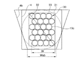
また、図17に、テープ心線積層体に対する溝の好ましい大きさを模式的に表した図を示す。
上述したように、SZスペーサの場合には溝4に対してテープ心線積層体30が長手方向に沿って回転する。そのため、溝4の断面視における大きさを、テープ心線積層体30の外接円33を内包できる大きさにすると良い。これにより、溝4内でテープ心線積層体30がその積層状態を保ったまま無理なく回転できるようになり、光ファイバ11に無理な歪みが加わることを防いで伝送損失の増加を抑制できる。また、テープ心線積層体30における光ファイバテープ心線10cの積層ずれを交互にすることで、外接円33の半径が小さくなり、それに伴い溝4の大きさも小さくできる。
Moreover, the figure which represented typically the preferable magnitude | size of the groove | channel with respect to a tape core laminated body in FIG. 17 is shown.
As described above, in the case of the SZ spacer, the tape core laminated
また、ほぼ長方形断面の溝4の代わりに、略台形の溝4bとしても良い。その場合、溝4bの底部における溝幅Wsbを、収容した光ファイバテープ心線10cの幅W以上とすることで、溝4bの底に配置された光ファイバテープ心線10cに対する側圧の付加を防止できる。
Moreover, it is good also as the substantially trapezoidal groove |
また、テープ心線積層体30の外接円33の直径2Rは、テープ心線積層体30の最下部と最上部に位置する光ファイバテープ心線10cに外接する四角形31の対角線32の長さから、四角形31の頂点とテープ心線積層体30との距離を除いた長さを算出して求めることができる。すなわち、図17における四角形31の左上部分を拡大した図18に示されるそれぞれの長さを用いて、次式(1)〜(3)により外接円33の直径2Rが求められる。
2R={(nT−(n−1)z)2+(W+P/2)2}1/2−2C ・・・(1)
z=T−(T2−(P/2)2)1/2 ・・・(2)
C={(T/2)2+(d/2+t2)2}1/2−{d/2+(t+t2)/2} ・・・(3)
なお、この式(1)〜(3)において、Wは光ファイバテープ心線10cの幅、nは光ファイバテープ心線10cの積層枚数、Tは光ファイバテープ心線10cの厚さ、dは光ファイバ11の外径、fは光ファイバテープ心線10cに含まれる光ファイバ11の数、zは隣接する光ファイバテープ心線10c同士のオーバーラップ長さ、Cは四角形31の頂点とテープ心線積層体30との距離、t2は光ファイバテープ心線10c縁辺における外被12cの厚さである。
The diameter 2R of the circumscribed
2R = {(nT− (n−1) z) 2 + (W + P / 2) 2 } 1/2 −2C (1)
z = T− (T 2 − (P / 2) 2 ) 1/2 (2)
C = {(T / 2) 2 + (d / 2 + t 2 ) 2 } 1/2 − {d / 2 + (t + t 2 ) / 2} (3)
In the formulas (1) to (3), W is the width of the
また、図17に示した形態ではテープ心線積層体30を構成する光ファイバテープ心線10cが偶数枚であり、四角形31の対角線長さは式(1)中の{(nT−(n−1)z)2+(W+P/2)2}1/2の項により算出されるが、図19に示す形態のようにテープ心線積層体30aを構成する光ファイバテープ心線10cが奇数である場合には、テープ心線積層体30aに外接する四角形31aの対角線長さは{(nT−(n−1)z)2+W2}1/2により算出される。そのため、テープ心線積層体30aが奇数の光ファイバテープ心線10cにより構成される場合には、外接円33aを求めるにあたって上記式(1)の代わりに次式(4)を用いると良い。
2R={(nT−(n−1)z)2+W2}1/2−2C ・・・(4)
In the embodiment shown in FIG. 17, the optical
2R = {(nT− (n−1) z) 2 + W 2 } 1/2 −2C (4)
また、図20及び図21に示すように、溝4c,4eの底部の断面形状を円弧形状として、その円弧部分4d,4fの半径を外接円33,33aの半径以上とすることで、溝4c,4e内でテープ心線積層体30,30aがスムースに回転できるようになる。これにより、伝送損失の増加をより効果的に防ぐことができる。
Also, as shown in FIGS. 20 and 21, the cross-sectional shape of the bottom of the
1 光ファイバケーブル
2 抗張力体
3 スペーサ
4 溝
5 押さえ巻き
6 シース
10 光ファイバテープ心線
11 光ファイバ
12 外被(樹脂)
13 ガラスファイバ
14 一次保護被覆
15 二次保護被覆
16 凹部
17 底部
DESCRIPTION OF
13
Claims (30)
前記光ファイバテープ心線は、光ファイバが複数本並列され、これらの複数本の前記光ファイバの全長が樹脂により一体化されており、前記光ファイバテープ心線の厚さの最大値をT(μm)、前記光ファイバの外径をd(μm)としたときに、T≦d+40(μm)であることを特徴とする光ファイバケーブル。 One or a plurality of optical fiber ribbons are disposed on the inner side of the spacer in which a substantially spiral groove is formed on the outer peripheral surface of a substantially cylindrical plastic long body having a tensile body at the center. A fiber optic cable housed in layers,
In the optical fiber ribbon, a plurality of optical fibers are juxtaposed, and the total length of the optical fibers is integrated with a resin, and the maximum thickness of the optical fiber ribbon is T ( μm), and T ≦ d + 40 (μm) when the outer diameter of the optical fiber is d (μm).
前記光ファイバテープ心線は、光ファイバが複数本並列され、これらの複数本の前記光ファイバの全長及び並列した状態の全周が樹脂により覆われて一体化されており、前記光ファイバテープ心線の厚さの最大値をT(μm)、前記光ファイバの外径をd(μm)としたときに、T≦d+40(μm)であることを特徴とする光ファイバケーブル。 One or a plurality of optical fiber ribbons are disposed on the inner side of the spacer in which a substantially spiral groove is formed on the outer peripheral surface of a substantially cylindrical plastic long body having a tensile body at the center. A fiber optic cable housed in layers,
The optical fiber tape core is formed by arranging a plurality of optical fibers in parallel and covering and integrating the total length of the plurality of optical fibers and the entire circumference of the optical fibers with a resin. An optical fiber cable, wherein T ≦ d + 40 (μm), where T (μm) is the maximum value of the thickness of the wire and d (μm) is the outer diameter of the optical fiber.
前記光ファイバテープ心線は、隣接した前記光ファイバ同士が互いに接触して配置されていることを特徴とする光ファイバケーブル。 The optical fiber cable according to claim 1 or 2,
The optical fiber cable, wherein the adjacent optical fibers are arranged in contact with each other.
前記光ファイバテープ心線は、隣接した少なくとも2本の前記光ファイバ同士が、互いに接触しておらず、かつ、10(μm)以下の間隔を有して配置されていることを特徴とする光ファイバケーブル。 The optical fiber cable according to claim 1 or 2,
In the optical fiber ribbon, at least two adjacent optical fibers are not in contact with each other, and are arranged with an interval of 10 (μm) or less. Fiber cable.
前記光ファイバテープ心線は、T≧d+1(μm)であることを特徴とする光ファイバケーブル。 The optical fiber cable according to any one of claims 1 to 4,
An optical fiber cable, wherein the optical fiber ribbon is T ≧ d + 1 (μm).
前記光ファイバテープ心線の前記樹脂には、隣接する前記光ファイバの間の窪みに応じた凹部が形成されていることを特徴とする光ファイバケーブル。 The optical fiber cable according to any one of claims 1 to 5,
The resin of the optical fiber ribbon is formed with a recess corresponding to a recess between adjacent optical fibers.
前記光ファイバテープ心線は、T≦d+30(μm)であることを特徴とする光ファイバケーブル。 The optical fiber cable according to claim 6,
The optical fiber cable is characterized in that the optical fiber ribbon is T ≦ d + 30 (μm).
前記光ファイバテープ心線は、前記凹部の深さをY(μm)としたときに、(T−d)/2Y≦4.0(μm)であることを特徴とする光ファイバケーブル。 The optical fiber cable according to claim 6 or 7,
The optical fiber cable is characterized in that (T−d) /2Y≦4.0 (μm) when the depth of the recess is Y (μm).
前記光ファイバテープ心線は、前記凹部における前記光ファイバテープ心線の厚さをg(μm)としたときに、g≦dであることを特徴とする光ファイバケーブル。 An optical fiber cable according to claim 8,
The optical fiber cable is characterized in that g ≦ d when the thickness of the optical fiber ribbon in the recess is g (μm).
前記光ファイバテープ心線は、g≦0.8dであることを特徴とする光ファイバケーブル。 An optical fiber cable according to claim 9,
An optical fiber cable, wherein the optical fiber ribbon is g ≦ 0.8d.
前記光ファイバテープ心線に含まれる前記光ファイバの並列ピッチをP(μm)、前記光ファイバテープ心線に含まれる前記光ファイバの数の1/2以下である0を含む自然数をmとしたときに、複数枚の前記光ファイバテープ心線が、隣接した光ファイバテープ心線に対して、前記光ファイバテープ心線の幅方向にmP+P/2(μm)だけずれて積層されていることを特徴とする光ファイバケーブル。 The optical fiber cable according to any one of claims 6 to 10,
The parallel pitch of the optical fibers included in the optical fiber ribbon is P (μm), and a natural number including 0 which is 1/2 or less of the number of the optical fibers included in the optical fiber ribbon is m. Sometimes, a plurality of the optical fiber ribbons are stacked with a deviation of mP + P / 2 (μm) in the width direction of the optical fiber ribbon with respect to the adjacent optical fiber ribbons. Features an optical fiber cable.
前記mが0であることを特徴とする光ファイバケーブル。 An optical fiber cable according to claim 11,
The optical fiber cable, wherein m is 0.
複数枚の前記光ファイバテープ心線が、隣接した前記光ファイバテープ心線に対して幅方向に順次交互にずれて積層されていることを特徴とする光ファイバケーブル。 An optical fiber cable according to claim 12,
An optical fiber cable, wherein a plurality of the optical fiber ribbons are stacked alternately and sequentially shifted in the width direction with respect to the adjacent optical fiber ribbons.
前記光ファイバテープ心線は、T≦d+25(μm)であることを特徴とする光ファイバケーブル。 The optical fiber cable according to any one of claims 1 to 4,
An optical fiber cable, wherein the optical fiber ribbon is T ≦ d + 25 (μm).
前記光ファイバテープ心線は、その横断面内における、隣接する2本の前記光ファイバの各中心を結ぶ直線に垂直で、かつ前記2本の光ファイバの各中心をそれぞれ通る2本の直線で区画される内側の領域で、
ヤング率をE、断面積をSとしたときに、前記光ファイバのES積の和に対する、前記樹脂のES積の比が、0.026以下であることを特徴とする光ファイバケーブル。 The optical fiber cable according to any one of claims 1 to 14,
The optical fiber ribbons are two straight lines passing through the centers of the two optical fibers perpendicular to a straight line connecting the centers of the two adjacent optical fibers in the cross section. In the inner area to be partitioned,
The ratio of the ES product of the resin to the sum of the ES products of the optical fibers when the Young's modulus is E and the cross-sectional area is S is 0.026 or less.
前記光ファイバテープ心線は、その横断面内における、隣接する2本の前記光ファイバの各中心を結ぶ直線に垂直で、かつ前記2本の光ファイバの各中心をそれぞれ通る2本の直線で区画される内側の領域で、
前記光ファイバのES積の和に対する、前記樹脂のES積の比が、0.020以下であることを特徴とする光ファイバケーブル。 The optical fiber cable according to claim 15,
The optical fiber ribbons are two straight lines passing through the centers of the two optical fibers perpendicular to a straight line connecting the centers of the two adjacent optical fibers in the cross section. In the inner area to be partitioned,
The ratio of the ES product of the resin to the sum of the ES products of the optical fibers is 0.020 or less.
前記光ファイバテープ心線は、前記光ファイバ1本あたりの前記光ファイバと前記樹脂との密着力が0.025(gf)から0.25(gf)の範囲内であることを特徴とする光ファイバケーブル。 The optical fiber cable according to any one of claims 1 to 16,
In the optical fiber ribbon, the optical fiber and the resin per one optical fiber have an adhesion force between 0.025 (gf) and 0.25 (gf). Fiber cable.
前記光ファイバテープ心線は、前記樹脂の降伏点応力が20(MPa)から45(MPa)の範囲内であることを特徴とする光ファイバケーブル。 The optical fiber cable according to any one of claims 1 to 17,
The optical fiber cable, wherein the resin has a yield point stress of 20 (MPa) to 45 (MPa).
前記溝は、前記スペーサの長尺方向に沿って一方向の螺旋状に形成されていることを特徴とする光ファイバケーブル。 The optical fiber cable according to any one of claims 1 to 18,
The groove is formed in a spiral shape in one direction along the longitudinal direction of the spacer.
収容された全ての前記光ファイバにおける、波長1.26(μm)から1.65(μm)の範囲内の何れかの波長のリンク偏波モード分散が、0.05(ps/km1/2)以下であることを特徴とする光ファイバケーブル。 The optical fiber cable according to claim 19,
The link polarization mode dispersion of any wavelength within the wavelength range of 1.26 (μm) to 1.65 (μm) in all the optical fibers accommodated is 0.05 (ps / km 1/2). ) An optical fiber cable characterized by:
前記溝は、前記スペーサの長尺方向に沿って交互に反転した螺旋状に形成されていることを特徴とする光ファイバケーブル。 The optical fiber cable according to any one of claims 1 to 18,
The optical fiber cable is characterized in that the groove is formed in a spiral shape that is alternately inverted along the longitudinal direction of the spacer.
収容された全ての前記光ファイバにおける、波長1.26(μm)から1.65(μm)の範囲内の何れかの波長のリンク偏波モード分散が、0.2(ps/km1/2)以下であることを特徴とする光ファイバケーブル。 The optical fiber cable according to claim 21,
The link polarization mode dispersion of any wavelength within the wavelength range of 1.26 (μm) to 1.65 (μm) in all the optical fibers accommodated is 0.2 (ps / km 1/2). ) An optical fiber cable characterized by:
収容された全ての前記光ファイバにおける、波長1.26(μm)から1.65(μm)の範囲内の何れかの波長のリンク偏波モード分散が、0.1(ps/km1/2)以下であることを特徴とする光ファイバケーブル。 The optical fiber cable according to claim 21,
The link polarization mode dispersion of any wavelength within the wavelength range of 1.26 (μm) to 1.65 (μm) in all the optical fibers accommodated is 0.1 (ps / km 1/2). ) An optical fiber cable characterized by:
前記溝の内側に、複数枚の前記光ファイバテープ心線が、隣接した前記光ファイバテープ心線に対して幅方向に前記光ファイバの並列ピッチの半分の長さだけ順次交互にずれて積層されており、
前記光ファイバテープ心線の前記樹脂には、隣接する前記光ファイバの間の窪みに応じた凹部が形成されており、
前記溝は、断面視において、積層された前記光ファイバテープ心線からなるテープ心線積層体の外接円を内包する大きさであることを特徴とする光ファイバケーブル。 The optical fiber cable according to claim 21,
Inside the groove, a plurality of the optical fiber ribbons are sequentially and alternately shifted in the width direction by half the parallel pitch of the optical fibers with respect to the adjacent optical fiber ribbons. And
The resin of the optical fiber ribbon is formed with a recess corresponding to a recess between the adjacent optical fibers,
The optical fiber cable, wherein the groove has a size that encloses a circumscribed circle of a laminated core of optical fiber tapes formed of the laminated optical fiber ribbons in a sectional view.
前記溝の断面が略台形であり、溝の底部における溝幅が、収容した前記光ファイバテープ心線の幅以上であることを特徴とする光ファイバケーブル。 An optical fiber cable according to claim 24,
The cross section of the groove is substantially trapezoidal, and the groove width at the bottom of the groove is equal to or greater than the width of the accommodated optical fiber ribbon.
前記溝の断面において、溝の底部が円弧形状をなし、当該円弧の半径が前記外接円の半径以上であることを特徴とする光ファイバケーブル。 An optical fiber cable according to claim 24,
In the cross section of the groove, the bottom of the groove has an arc shape, and the radius of the arc is not less than the radius of the circumscribed circle.
前記光ファイバは、波長1.55(μm)におけるピーターマン−I(Petermann−I)の定義によるモードフィールド径が10(μm)以下であることを特徴とする光ファイバケーブル。 An optical fiber cable according to any one of claims 1 to 26, wherein
The optical fiber has a mode field diameter of 10 (μm) or less according to the definition of Petermann-I at a wavelength of 1.55 (μm).
前記光ファイバは、波長1.55(μm)におけるピーターマン−I(Petermann−I)の定義によるモードフィールド径が8(μm)以下であることを特徴とする光ファイバケーブル。 The optical fiber cable according to any one of claims 1 to 27,
The optical fiber has a mode field diameter of 8 (μm) or less according to the definition of Petermann-I at a wavelength of 1.55 (μm).
前記光ファイバテープ心線は、前記光ファイバを分岐するときの損失増加が1.0(dB)以下であることを特徴とする光ファイバケーブル。 The optical fiber cable according to any one of claims 1 to 28, wherein:
The optical fiber cable has an increase in loss when the optical fiber is branched is 1.0 (dB) or less.
前記光ファイバテープ心線は、前記光ファイバを分岐するときの損失増加が0.5(dB)以下であることを特徴とする光ファイバケーブル。 The optical fiber cable according to any one of claims 1 to 29,
The optical fiber cable has a loss increase of 0.5 (dB) or less when the optical fiber is branched.
Priority Applications (1)
| Application Number | Priority Date | Filing Date | Title |
|---|---|---|---|
| JP2004191199A JP2005037936A (en) | 2003-07-01 | 2004-06-29 | Optical fiber cable |
Applications Claiming Priority (2)
| Application Number | Priority Date | Filing Date | Title |
|---|---|---|---|
| JP2003189779 | 2003-07-01 | ||
| JP2004191199A JP2005037936A (en) | 2003-07-01 | 2004-06-29 | Optical fiber cable |
Publications (2)
| Publication Number | Publication Date |
|---|---|
| JP2005037936A true JP2005037936A (en) | 2005-02-10 |
| JP2005037936A5 JP2005037936A5 (en) | 2005-09-29 |
Family
ID=34220569
Family Applications (1)
| Application Number | Title | Priority Date | Filing Date |
|---|---|---|---|
| JP2004191199A Pending JP2005037936A (en) | 2003-07-01 | 2004-06-29 | Optical fiber cable |
Country Status (1)
| Country | Link |
|---|---|
| JP (1) | JP2005037936A (en) |
Cited By (7)
| Publication number | Priority date | Publication date | Assignee | Title |
|---|---|---|---|---|
| JP2006301531A (en) * | 2005-04-25 | 2006-11-02 | Swcc Showa Cable Systems Co Ltd | Optical fiber tape, optical cable and method for separating single core of optical fiber tape |
| JP2007108424A (en) * | 2005-10-13 | 2007-04-26 | Sumitomo Electric Ind Ltd | Optical cable |
| JP2008281687A (en) * | 2007-05-09 | 2008-11-20 | Ube Nitto Kasei Co Ltd | Sz slot and manufacturing method thereof |
| JP2008304779A (en) * | 2007-06-08 | 2008-12-18 | Nippon Telegr & Teleph Corp <Ntt> | Optical fiber cable |
| JP2011022477A (en) * | 2009-07-17 | 2011-02-03 | Furukawa Electric Co Ltd:The | Optical fiber ribbon |
| JP2016184170A (en) * | 2016-05-13 | 2016-10-20 | 住友電気工業株式会社 | Optical cable |
| JP2016194652A (en) * | 2015-04-01 | 2016-11-17 | 住友電気工業株式会社 | Optical fiber cable |
-
2004
- 2004-06-29 JP JP2004191199A patent/JP2005037936A/en active Pending
Cited By (7)
| Publication number | Priority date | Publication date | Assignee | Title |
|---|---|---|---|---|
| JP2006301531A (en) * | 2005-04-25 | 2006-11-02 | Swcc Showa Cable Systems Co Ltd | Optical fiber tape, optical cable and method for separating single core of optical fiber tape |
| JP2007108424A (en) * | 2005-10-13 | 2007-04-26 | Sumitomo Electric Ind Ltd | Optical cable |
| JP2008281687A (en) * | 2007-05-09 | 2008-11-20 | Ube Nitto Kasei Co Ltd | Sz slot and manufacturing method thereof |
| JP2008304779A (en) * | 2007-06-08 | 2008-12-18 | Nippon Telegr & Teleph Corp <Ntt> | Optical fiber cable |
| JP2011022477A (en) * | 2009-07-17 | 2011-02-03 | Furukawa Electric Co Ltd:The | Optical fiber ribbon |
| JP2016194652A (en) * | 2015-04-01 | 2016-11-17 | 住友電気工業株式会社 | Optical fiber cable |
| JP2016184170A (en) * | 2016-05-13 | 2016-10-20 | 住友電気工業株式会社 | Optical cable |
Similar Documents
| Publication | Publication Date | Title |
|---|---|---|
| TWI286621B (en) | Optical fiber ribbon and optical fiber cable using the same | |
| JP4055000B2 (en) | Optical fiber cable, optical fiber cable manufacturing method, and optical fiber cable manufacturing apparatus | |
| JP4297372B2 (en) | Optical fiber cable, optical fiber extraction method, and optical fiber extraction tool | |
| JP4252991B2 (en) | Optical fiber cable, optical fiber extraction method, and optical fiber extraction tool | |
| WO2014054129A1 (en) | Optical fiber tape core | |
| JP2007272060A (en) | Optical fiber ribbon and optical fiber cable | |
| JP6273847B2 (en) | Optical fiber and optical cable | |
| JP3664254B2 (en) | Optical fiber ribbon and manufacturing method thereof | |
| WO2005101080A1 (en) | Optical fiber tape unit and optical fiber cable | |
| JP2014074910A (en) | Coated optical fiber tape | |
| JP2005037936A (en) | Optical fiber cable | |
| JP2005043877A (en) | Optical fiber cable | |
| WO2020162501A1 (en) | Intermittent connection-type optical fiber tape core wire, optical fiber cable, and method for manufacturing intermittent connection-type optical fiber tape core wire | |
| JP2005070770A (en) | Optical fiber cable | |
| JP4850732B2 (en) | Optical fiber tape and optical cable | |
| JP2005165363A (en) | Optical fiber ribbon | |
| JP2015018053A (en) | Optical cable | |
| JP4249202B2 (en) | Optical fiber tape and optical cable | |
| JP2014085512A (en) | Optical fiber tape core wire and optical fiber cable | |
| JP4094630B2 (en) | Single fiber separation method of optical fiber tape | |
| JP3951133B2 (en) | Fiber optic cable | |
| JP2006208940A (en) | Optical fiber ribbon and optical cable | |
| JP2005222080A (en) | Optical fiber ribbon and manufacturing method thereof | |
| JP4442296B2 (en) | Optical fiber tape unit and optical fiber cable | |
| JP2005249977A (en) | Fiber optic cable |
Legal Events
| Date | Code | Title | Description |
|---|---|---|---|
| A521 | Request for written amendment filed |
Free format text: JAPANESE INTERMEDIATE CODE: A523 Effective date: 20050729 |
|
| A621 | Written request for application examination |
Free format text: JAPANESE INTERMEDIATE CODE: A621 Effective date: 20050729 |
|
| A131 | Notification of reasons for refusal |
Free format text: JAPANESE INTERMEDIATE CODE: A131 Effective date: 20060802 |
|
| A02 | Decision of refusal |
Free format text: JAPANESE INTERMEDIATE CODE: A02 Effective date: 20061122 |