JP2005018564A - Inner force sense imparting type input device - Google Patents
Inner force sense imparting type input device Download PDFInfo
- Publication number
- JP2005018564A JP2005018564A JP2003184502A JP2003184502A JP2005018564A JP 2005018564 A JP2005018564 A JP 2005018564A JP 2003184502 A JP2003184502 A JP 2003184502A JP 2003184502 A JP2003184502 A JP 2003184502A JP 2005018564 A JP2005018564 A JP 2005018564A
- Authority
- JP
- Japan
- Prior art keywords
- electromagnetic coil
- electromagnetic
- input device
- base
- rotation angle
- Prior art date
- Legal status (The legal status is an assumption and is not a legal conclusion. Google has not performed a legal analysis and makes no representation as to the accuracy of the status listed.)
- Ceased
Links
- 239000000696 magnetic material Substances 0.000 claims abstract description 4
- 239000000463 material Substances 0.000 claims description 18
- 239000004033 plastic Substances 0.000 claims description 8
- 238000001514 detection method Methods 0.000 claims description 3
- 230000035807 sensation Effects 0.000 description 7
- 230000007423 decrease Effects 0.000 description 4
- XEEYBQQBJWHFJM-UHFFFAOYSA-N Iron Chemical compound [Fe] XEEYBQQBJWHFJM-UHFFFAOYSA-N 0.000 description 3
- 230000001133 acceleration Effects 0.000 description 3
- 239000011810 insulating material Substances 0.000 description 2
- 238000000034 method Methods 0.000 description 2
- 229920003002 synthetic resin Polymers 0.000 description 2
- 239000000057 synthetic resin Substances 0.000 description 2
- 230000005540 biological transmission Effects 0.000 description 1
- 238000010586 diagram Methods 0.000 description 1
- 230000000694 effects Effects 0.000 description 1
- 230000004907 flux Effects 0.000 description 1
- 230000006870 function Effects 0.000 description 1
- 229910052742 iron Inorganic materials 0.000 description 1
- 239000002184 metal Substances 0.000 description 1
- 229910052751 metal Inorganic materials 0.000 description 1
- 238000004804 winding Methods 0.000 description 1
Images
Landscapes
- Mechanical Control Devices (AREA)
Abstract
Description
【0001】
【発明の属する技術分野】
本発明は、電気機器や車載用電気機器に使用される入力装置に係り、ノブに回転角に応じた回転力を与えることにより、ノブから操作者に所定の力学的な感触(力覚)を与える力覚付与型入力装置に関する。
【0002】
【従来の技術】
従来から、力覚付与型入力装置には、手動で回転操作されるノブと、このノブの回転角を検出するロータリーエンコーダと、ノブに回転力を与えるモータと、前記ロータリーエンコーダにより検出された回転角に応じてモータを制御すると共に、ノブの操作対象物である別の装置にノブの回転角に応じた操作信号を出力するコントローラとを備えたものがある(例えば、特許文献1参照)。
【0003】
このように構成された力覚付与型入力装置は、ノブを手動で回転操作することにより、電気機器、例えば車載用電気機器を操作する操作信号を出力するものであって、車載用エアコンの風量の調節や吹き出し口の切り換え、ラジオの音量やチューナーの調整、オーディオの音量や音質の調整などが操作対象となる。
【0004】
車載用エアコンの風量を調整する場合、例えば、ノブを風量を増加させる方向に回転すると、ノブの回転方向と反対方向の回転力がモータからノブに与えられ、風量を増加させる方向におけるノブの回転角の増大に従って、ノブに与えられる回転方向と反対方向の回転力が増大するように設定される。つまり、操作者は、ノブから与えられる抵抗力の増加に伴う抵抗感触(力覚)により、風量を増加させる方向にどの程度ノブを回転させたかを把握することができる。
【0005】
尚、力覚付与型入力装置には、上述のように力覚として抵抗感触が得られるようにしたものの他に、ノブに回転方向と同方向の回転力を与えることにより力覚として加速感触が得られるようにしたものや、ノブの回転角が所定の回転角を超える際にノブに与える回転力を反転させることにより力覚としてクリック感触が得られるようにしたものなどがある。
【0006】
【特許文献1】
特開2003−50639号公報
【0007】
【発明が解決しようとする課題】
しかしながら、上述の力覚付与型入力装置においては、操作者が操作ノブを操作する場合に、モータから操作ノブに与えられる抵抗力の増減に伴う抵抗感触及び加速感触(力覚)により、その操作状態を把握するようになっているが、使用するモータが一種類のため、発生するトルクフィーリング(感触)が全て同じような感触となってしまい、多様なトルクフィーリングを発生させることができないという問題があった。
【0008】
従って、本発明では上述した問題点を解決し、複数のモータを使用することなしに、多様なトルクフィーリングを簡単な構成で容易に発生させることができる、操作性の優れた力覚付与型入力装置を提供することを目的とする。
【0009】
【課題を解決するための手段】
上記課題を解決するために本発明では第1の解決手段として、駆動軸を有し回転可能な駆動体と、この駆動体の回転方向及び回転角を検出するロータリーエンコーダと、前記駆動体の一端側に取り付けられた磁性材からなるアーマチュアと、このアーマチュアと前記駆動体の軸線方向に空間を介して対向して配設された電磁コイルと、この電磁コイルが取り付けられた基台とを備え、前記電磁コイルを複数個設け、この複数個の電磁コイルをそれぞれ個別の板ばねを介して前記基台に取り付けると共に、複数個の前記電磁コイルをそれぞれ異なる接触表面とした構成とした。
【0010】
また、第2の解決手段として、前記板ばねは、前記基台の上面側に固定される第1のばね片と、前記電磁コイルの下面側に固定される第2のばね片を有し、この第1及び第2のばね片により、前記電磁コイルを前記基台上に前記駆動体の軸線方向に移動可能に取り付けた構成とした。
また、第3の解決手段として、前記電磁コイルは、接触表面がゴム材からなる第1の電磁コイルと、接触表面がプラスチック材からなる第2の電磁コイルとで構成した。
【0011】
また、第4の解決手段として、前記第1の電磁コイルと、前記第2の電磁コイルをそれぞれ2個づつ設けると共に、十字方向に互いに対向させて前記基台上に配置した構成とした。
また、第5の解決手段として、前記ロータリーエンコーダからの検出信号に基づいて前記電磁コイルへ流す電流を制御する制御部を備え、この制御部で、前記駆動体の回転角度や回転位置に合わせて複数個の前記電磁コイルに流す電流を変化させることにより異なる力覚を発生させるようにした構成とした。
【0012】
【発明の実施の形態】
以下、本発明の実施形態を図1乃至図3に示す。図1は本発明に係る力覚付与型入力装置の構成を示す斜視図、図2は本発明に係る力覚付与型入力装置の板ばねを示す平面図、図3は制御部を含む電気系統のブロック図である。
【0013】
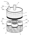
図1において、駆動体1は、合成樹脂などの絶縁材で略円盤状に形成されている。この駆動体1の上面側の中央には、円筒状の駆動軸2が上方へ突出して設けられており、この駆動軸2の先端側には図示しない操作ノブが取り付けられている。この操作ノブは図示しない筐体に軸支されて回転可能に取り付けられており、この操作ノブを操作者が摘んで回転操作を行うことにより駆動体1が回転可能となっている。
【0014】
また、駆動体1の下面側には、同じく円盤状の鉄板からなるアーマチュア3が取り付けられており、このアーマチュア3は駆動体1の回転に伴って回転するものとなっている。また、このアーマチュア3は後述する電磁コイル6と一定の空間を保持した状態で対向して配置されたものとなっている。
【0015】
ロータリーエンコーダ4は、駆動体1の駆動軸2に設けられ、駆動軸2の回転角、すなわち操作ノブの回転角を検出し、その回転角に相当する回転角信号を出力するもので、このロータリーエンコーダ4は、駆動軸2に固着され、縁に円周方向に沿って多数のコード、例えばスリットが配列されたコード板4aと、このコード板4aのスリットに向かって光を放つ発光部及びスリットを通過した光を受光してそのスリットが示すコード板4aの回転角、すなわち操作ノブの回転角に相当する回転角信号を出力する受光部からなるセンサ部4bとを有している。そして、このセンサ部4bは、操作ノブが回転可能に軸支される筐体(図示せず)に取り付けられている。
【0016】
基台5は、同じく合成樹脂などの絶縁材で略円盤状に形成されている。この基台5の上面側には、複数個の電磁コイル6が円板状の板ばね7を介して取り付けられている。電磁コイル6は、鉄心にコイルを円環状に巻回して形成された電磁石からなり、この電磁石のコイルに、後述する制御部8からの制御信号が出力されたときに発生する磁力の作用で、対向して配置された前記アーマチュア3に吸着することにより駆動体1の回転を制御する電磁ブレーキを構成している。
【0017】
また、前記電磁コイル6は、上面の接触表面がゴム材からなる、2個の第1の電磁コイル6a、6bと、同じく上面の接触表面がプラスティック材からなる、2個の第2の電磁コイル6c、6dとで構成されている。この場合、第1の電磁コイル6aが第1電磁ブレーキ、第1の電磁コイル6bが第2電磁ブレーキを構成し、第2の電磁コイル6cが第3電磁ブレーキ、第2の電磁コイル6dが第4電磁ブレーキを構成している。
【0018】
この場合、前記第1の電磁コイル6a、6bと、第2の電磁コイル6c、6dは、十字方向に互いに対向させた状態で前記基台5の上面に配置された構成となっている。また、第1の電磁コイル6a、6bと、第2の電磁コイル6c、6dとは、それぞれ上面の接触表面側が、前記アーマチュア3と一定の空間を保持した状態で対向して配置されたものとなっている。尚、前記基台5は図示しない筐体に取り付けられている。
【0019】
このように、電磁コイル6を、接触表面がゴム材からなる第1の電磁コイル6a、6bと、接触表面がプラスチック材からなる第2の電磁コイル6c、6dとで構成したので、汎用の材料を使用できるので加工が容易なため、特別な設備や工程を要することなしに、異なる接触表面を持つ電磁コイルを簡単に形成することができる。また、第1の電磁コイル6a、6bと、第2の電磁コイル6c、6dをそれぞれ2個づつ設けると共に、十字方向に互いに対向させて前記基台5の上面に配置するようにしたので、トルクフィーリングの発生時には、バランスのよいフィーリングが得られ、操作性の向上が図れるものとなっている。
【0020】
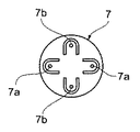
板ばね7は、ばね性を有する薄板金属板からなり、十字状に対向して形成された二対のばね片を有している。このばね片は、前記基台5の上面側に固定される、下方へ切り曲げされた一対の第1のばね片7aと、前記電磁コイル6の下面側に固定される上方へ切り曲げされた一対の第2のばね片7bとを有し、この第1及び第2のばね片7a、7bの有するばね性により、前記電磁コイル6が前記基台5の上面に前記駆動体1の軸線方向に移動可能に取り付けられている。
【0021】
このように、第1及び第2のばね片7a、7bにより、電磁コイル6を基台5の上面に駆動体1の軸線方向に移動可能に取り付けたことから、簡単な構成で複数個の電磁コイル6を基台5上に個々に可動状態で取り付けることができるものとなる。
【0022】
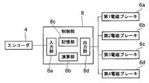
制御部8は、入力部8a、演算部8b、記憶部8c、出力部8dを有している。入力部8aは、ロータリーエンコーダ4から出力された回転角信号と、回転方向信号とが入力されるものである。演算部8bは、入力部8aに入力された回転角信号と、回転方向信号に応じてそれぞれの電磁ブレーキを制御する制御信号の値(電圧値)を演算するものである。出力部8dは、演算部8bによる演算結果に応じて、それぞれの電磁ブレーキに制御信号を出力するものである。
【0023】
尚、演算部8bは、例えば、操作ノブが所定の回転角に達したかどうかを判断し、所定の回転角に達したと判断したときに、電磁ブレーキにより操作ノブの回転を阻止する旨を決定するようになっている。そして、記憶部8cには、制御部8を動作させるための制御プログラムと、演算部8bによる制御信号の値の演算に使用される関数と、操作ノブのロックの継続と解除を決定するための演算式とを予め記憶させている。
【0024】
次に、上記構成の力覚付与型入力装置の動作について説明する。
まず、操作ノブを回転させて、駆動軸2を介して駆動体1を回転すると、駆動軸2に固着されたロータリーエンコーダ4のコード板4aが回転し、センサ部4bにより駆動体1の回転角の信号が制御部8の入力部8aに入力される。制御部8は駆動体1の回転角に応じて所定の電流を電磁コイル6に送るように指示を出す。電流を受けた電磁コイル6は対向するアーマチュア3を吸引する。アーマチュア3は電磁コイル6から吸引力を受けるが、この時、基台5と電磁コイル6との間に介在された板ばね7がその板厚方向に伸びて、電磁コイル6の上面の接触表面がアーマチュア3と吸着される。
【0025】
この状態で、操作ノブを回転させようとすると、アーマチュア3が電磁コイル6に吸着されているので、アーマチュア3と電磁コイル6との間に電磁コイル6の吸引力に応じた摩擦力が発生し、操作ノブを回転させようとする回転トルクが変化する。このようにして、操作ノブの回転角に応じて、制御部8に記憶されている所定の電流により所定の回転トルクが得られるようになっている。
そして、電磁コイル6への通電を止めると、電磁コイル6がアーマチュア3を吸引する吸引力は無くなるので、板ばね7が縮んで、アーマチュア3は電磁コイル6の接触表面から離れ、操作ノブはアーマチュア3の摩擦力がない状態になる。
【0026】
この場合、前記電磁コイル6は、アーマチュア3と吸着する接触表面が異なる複数の材料から形成されており、ゴム材から形成された第1の電磁コイル6a、6bと、プラスチック材から形成された第2の電磁コイル6c、6dとを、十字状にそれぞれ対向させて4個配置して構成してある。そして、制御部8が駆動体1の回転角に応じて所定の電流を電磁コイル6に通電する場合に、作動させる第1及び第2の電磁コイル6a、6b、6c、6dの対象を変えたり、通電する電流を、回転角度や回転位置に合わせて変化させることにより、その摩擦感触の異なる種々の電磁ブレーキが構成できるので、多様なトルクフィーリング(異なる力覚)を発生させることができるものとなっている。
【0027】
以上の動作を用いて、操作ノブを時計方向に回転すると、回転角の増加に伴って回転トルクが大きくなったり、その逆に、回転角の増加に伴って回転トルクが小さくなったりする操作ノブの感触(力覚)が得られるものとなり、これにより、例えばエアコンなどの風量の切り換えが行われるものとなる。
【0028】
すなわち、この時、演算部8bでは、操作ノブの回転角に応じた電磁ブレーキの制御信号の値の演算も行われる。そして、演算部8bにより算出された値の制御信号が出力部8dから電磁ブレーキに出力される。これにより、電磁ブレーキから操作ノブに回転操作に抵抗する力が加えられ、この力が操作ノブの回転角の増大に従って、その回転操作に抵抗する力が増大する。つまり、操作者は、操作ノブから与えられる抵抗力の増大に伴う抵抗感触(力覚)により、風量を増加させる方向(例えば時計方向)に操作ノブをどの程度回転させたかを把握することができるものとなる。
【0029】
また、操作ノブの回転角が所定の回転角に達すると、ロータリーエンコーダ4により所定の回転角が検出され、その所定の回転角に相当する回転角信号が制御部8の入力部8aに入力される。そして、演算部8bにより、記憶部8cに予め記憶されている演算式に基づいて、操作ノブの回転を阻止する旨が決定され、この決定に対するブレーキ制御信号が出力部8dから電磁ブレーキに出力される。これにより、操作ノブが所定の回転角を超えて回転することが阻止されるものとなる。
【0030】
上記した本発明の実施例によれば、電磁コイル6を複数個設け、この複数個の電磁コイル6を、それぞれ個別の板ばね7を介して個々にアーマチュア3と吸着可能なように基台5に取り付けると共に、複数個の電磁コイル6をそれぞれ異なる接触表面を持つ材料である、ゴム材とプラスチック材によりそれぞれ形成するようにしたため、操作ノブを操作して、操作ノブに与えられる抵抗力の増減に伴う力覚により、その操作状態を把握する際に、複数個の電磁コイル6のうち、接触表面の異なるゴム材からなる第1の電磁コイル6a、6bと、プラスチック材からなる第2の電磁コイル6c、6dをそれぞれ選択して作動させることにより、多様なトルクフィーリングを発生させることができるので、操作性の優れた力覚付与型入力装置を提供できるものとなっている。
【0031】
尚、上記した本発明の実施例においては、力覚として抵抗感触が得られる力覚付与型入力装置を挙げたが、本発明はこれに限るものではなく、力覚として加速する感触や、クリック感触が得られる力覚付与型入力装置にしてもよい。
また、ロータリーエンコーダ2はスリットを通して光の透過を検出するようにしたが、光を反射するコードを有するコード板を使用してもよい。
【0032】
【発明の効果】
以上説明したように、本発明の力覚付与型入力装置は、駆動軸を有し回転可能な駆動体と、駆動体の回転方向及び回転角を検出するロータリーエンコーダと、駆動体の一端側に取り付けられた磁性材からなるアーマチュアと、アーマチュアと駆動体の軸線方向に空間を介して対向して配設された電磁コイルと、電磁コイルが取り付けられた基台とを備え、電磁コイルを複数個設け、複数個の電磁コイルをそれぞれ個別の板ばねを介して基台に取り付けると共に、複数個の電磁コイルをそれぞれ異なる接触表面としたことから、操作ノブを操作して、操作ノブに与えられる抵抗力の増減に伴う力覚により、その操作状態を把握する際に、複数個の電磁コイルのうち接触表面の異なる電磁コイルを選択して作動させることにより、多様なトルクフィーリングを発生させることができるので、操作性の優れた力覚付与型入力装置を提供できる。
【0033】
また、板ばねは、基台の上面側に固定される第1のばね片と、電磁コイルの下面側に固定される第2のばね片を有し、第1及び第2のばね片により、電磁コイルを基台上に駆動体の軸線方向に移動可能に取り付けたことから、簡単な構成で複数個の電磁コイルを基台上に個々に可動状態で取り付けることができる。
また、電磁コイルは、接触表面がゴム材からなる第1の電磁コイルと、接触表面がプラスチック材からなる第2の電磁コイルとで構成したことから、加工が容易なため、特別な設備や工程を要することなしに、異なる接触表面を持つ電磁コイルを簡単に形成することができる。
【0034】
また、第1の電磁コイルと、第2の電磁コイルをそれぞれ2個づつ設けると共に、十字方向に互いに対向させて前記基台上に配置したことから、トルクフィーリングの発生時には、バランスのよいフィーリングが得られ、操作性の向上が図れる。
また、ロータリーエンコーダからの検出信号に基づいて電磁コイルへ流す電流を制御する制御部を備え、制御部で、駆動体の回転角度や回転位置に合わせて複数個の電磁コイルに流す電流を変化させることにより異なる力覚を発生させるようにしたことから、複数個の電磁コイルのうち接触表面の異なる電磁コイルを選択して作動させたり、接触表面の同じ電磁コイルでも電磁コイルに流す電流を変化させるなどの組み合わせを色々変えることにより、更に多様なトルクフィーリングを発生させることができるので、操作性の優れた力覚付与型入力装置を提供できる。
【図面の簡単な説明】
【図1】本発明の一実施形態である力覚付与型入力装置の構成を示す斜視図である。
【図2】本発明の力覚付与型入力装置の板ばねを示す平面図である。
【図3】本発明の力覚付与型入力装置の制御部を含む電気系統のブロック図である。
【符号の説明】
1 駆動体
2 駆動軸
3 アーマチュア
4 ロータリーエンコーダ
4a コード板
4b センサ部
5 基台
6 磁気コイル
6a,6b 第1の磁気コイル
6c,6d 第2の磁気コイル
7 板ばね
7a 第1のばね片
7b 第2のばね片
8 制御部[0001]
BACKGROUND OF THE INVENTION
The present invention relates to an input device used for an electric device or an on-vehicle electric device, and gives a predetermined mechanical feel (force sense) to an operator from the knob by giving the knob a rotational force according to a rotation angle. The present invention relates to a force imparting input device.
[0002]
[Prior art]
Conventionally, a force sense input device includes a knob that is manually rotated, a rotary encoder that detects a rotation angle of the knob, a motor that applies a rotational force to the knob, and a rotation detected by the rotary encoder. There is a device that controls a motor in accordance with the angle and includes a controller that outputs an operation signal in accordance with the rotation angle of the knob to another device that is an operation target of the knob (see, for example, Patent Document 1).
[0003]
The force sense input device configured in this way outputs an operation signal for operating an electric device, for example, an in-vehicle electric device, by manually rotating the knob, and the air volume of the in-vehicle air conditioner Adjustments and switching of the air outlet, radio volume and tuner adjustment, audio volume and sound quality adjustment, and so on.
[0004]
When adjusting the air volume of an in-vehicle air conditioner, for example, if the knob is rotated in the direction that increases the air volume, the rotating force in the direction opposite to the rotation direction of the knob is applied from the motor to the knob, and the knob rotates in the direction that increases the air volume. As the angle increases, the rotational force in the direction opposite to the rotational direction applied to the knob is set to increase. That is, the operator can grasp how much the knob has been rotated in the direction in which the air volume is increased, based on the resistance feeling (force sense) accompanying the increase in the resistance force applied from the knob.
[0005]
In addition to the force-sensing input device that provides a sense of resistance as a force sense as described above, an acceleration feel as a force sense is provided by applying a rotational force in the same direction as the rotational direction to the knob. There are ones that can be obtained, and ones that provide a click feeling as a force sense by reversing the rotational force applied to the knob when the rotational angle of the knob exceeds a predetermined rotational angle.
[0006]
[Patent Document 1]
JP 2003-50639 A
[Problems to be solved by the invention]
However, in the above-described haptic input device, when an operator operates the operation knob, the operation is performed by a resistance feeling and an acceleration feeling (force sensation) that accompany an increase or decrease in the resistance force applied from the motor to the operation knob. Although the state is grasped, since there is only one type of motor to be used, all the generated torque feelings (feels) become the same feeling, and various torque feelings cannot be generated. There was a problem.
[0008]
Therefore, the present invention solves the above-described problems, and can easily generate various torque feelings with a simple configuration without using a plurality of motors. An object is to provide an input device.
[0009]
[Means for Solving the Problems]
In order to solve the above-mentioned problems, the present invention provides, as a first solving means, a drive body that has a drive shaft and is rotatable, a rotary encoder that detects a rotation direction and a rotation angle of the drive body, and one end of the drive body. An armature made of a magnetic material attached to the side, an electromagnetic coil disposed opposite to the armature via a space in the axial direction of the drive body, and a base on which the electromagnetic coil is attached, A plurality of the electromagnetic coils are provided, and the plurality of electromagnetic coils are attached to the base via individual leaf springs, and the plurality of electromagnetic coils have different contact surfaces.
[0010]
Further, as a second solving means, the leaf spring has a first spring piece fixed to the upper surface side of the base and a second spring piece fixed to the lower surface side of the electromagnetic coil, With the first and second spring pieces, the electromagnetic coil is mounted on the base so as to be movable in the axial direction of the driving body.
As a third solution, the electromagnetic coil is composed of a first electromagnetic coil whose contact surface is made of a rubber material and a second electromagnetic coil whose contact surface is made of a plastic material.
[0011]
As a fourth solution, the first electromagnetic coil and the second electromagnetic coil are provided in pairs, and are arranged on the base so as to face each other in the cross direction.
Further, as a fifth solving means, a control unit for controlling a current flowing to the electromagnetic coil based on a detection signal from the rotary encoder is provided, and in this control unit, according to a rotation angle and a rotation position of the driving body. Different force senses were generated by changing the currents flowing through the plurality of electromagnetic coils.
[0012]
DETAILED DESCRIPTION OF THE INVENTION
Embodiments of the present invention are shown in FIGS. FIG. 1 is a perspective view showing a configuration of a haptic input device according to the present invention, FIG. 2 is a plan view showing a leaf spring of the haptic input device according to the present invention, and FIG. 3 is an electric system including a control unit. FIG.
[0013]
In FIG. 1, the drive body 1 is formed in a substantially disk shape with an insulating material such as synthetic resin. A cylindrical drive shaft 2 protrudes upward from the center of the upper surface of the drive body 1, and an operation knob (not shown) is attached to the distal end side of the drive shaft 2. This operation knob is rotatably supported by being pivotally supported by a housing (not shown), and the driver 1 can be rotated by an operator holding the operation knob and performing a rotation operation.
[0014]
Also, an armature 3 made of a disk-shaped iron plate is attached to the lower surface side of the drive body 1, and the armature 3 rotates with the rotation of the drive body 1. The armature 3 is arranged to face an
[0015]
The
[0016]
The
[0017]
The
[0018]
In this case, the first
[0019]
As described above, the
[0020]
The
[0021]
As described above, the
[0022]
The
[0023]
The
[0024]
Next, the operation of the haptic input device configured as described above will be described.
First, when the operating knob is rotated and the driving body 1 is rotated via the driving shaft 2, the
[0025]
If the operation knob is rotated in this state, the armature 3 is attracted to the
When the energization of the
[0026]
In this case, the
[0027]
When the operation knob is rotated clockwise using the above operation, the rotation torque increases as the rotation angle increases, and conversely, the operation torque decreases as the rotation angle increases. In this way, for example, the air volume of an air conditioner is switched.
[0028]
That is, at this time, the
[0029]
When the rotation angle of the operation knob reaches a predetermined rotation angle, the
[0030]
According to the above-described embodiment of the present invention, a plurality of
[0031]
In the above-described embodiments of the present invention, the haptic input device capable of obtaining a resistance sensation as a force sensation has been described. However, the present invention is not limited to this, and the sensation of acceleration as a sensation or click A force sense input device that provides a feeling may be used.
The rotary encoder 2 detects the transmission of light through the slit, but a code plate having a code that reflects light may be used.
[0032]
【The invention's effect】
As described above, the force sense input device of the present invention includes a drive body that has a drive shaft and is rotatable, a rotary encoder that detects a rotation direction and a rotation angle of the drive body, and one end side of the drive body. A plurality of electromagnetic coils, comprising: an armature made of a magnetic material attached; an electromagnetic coil disposed opposite to the armature in the axial direction of the drive body through a space; and a base to which the electromagnetic coil is attached. Since a plurality of electromagnetic coils are attached to the base via individual leaf springs, and the plurality of electromagnetic coils have different contact surfaces, the resistance given to the operation knob by operating the operation knob When grasping the operating state based on the force sensation associated with the increase or decrease in force, a variety of torque fluxes can be selected by selecting and operating electromagnetic coils having different contact surfaces from among a plurality of electromagnetic coils. It is possible to generate a-ring, it can be given an improved haptic feedback input device operability.
[0033]
Further, the leaf spring has a first spring piece fixed to the upper surface side of the base and a second spring piece fixed to the lower surface side of the electromagnetic coil. With the first and second spring pieces, Since the electromagnetic coils are mounted on the base so as to be movable in the axial direction of the driving body, a plurality of electromagnetic coils can be individually mounted on the base in a movable state with a simple configuration.
Further, since the electromagnetic coil is composed of the first electromagnetic coil whose contact surface is made of a rubber material and the second electromagnetic coil whose contact surface is made of a plastic material, it is easy to process. An electromagnetic coil having a different contact surface can be easily formed without the need for.
[0034]
In addition, two each of the first electromagnetic coil and the second electromagnetic coil are provided and arranged on the base so as to face each other in the cross direction. A ring is obtained and operability can be improved.
In addition, a control unit that controls a current that flows to the electromagnetic coil based on a detection signal from the rotary encoder is provided, and the control unit changes the current that flows to the plurality of electromagnetic coils in accordance with the rotation angle and rotation position of the drive body. Since different force sensations are generated by this, an electromagnetic coil with a different contact surface is selected and operated from among a plurality of electromagnetic coils, or the current flowing through the electromagnetic coil is changed even with the same electromagnetic coil on the contact surface. Since various torque feelings can be generated by changing various combinations such as the above, it is possible to provide a haptic input device with excellent operability.
[Brief description of the drawings]
FIG. 1 is a perspective view showing a configuration of a haptic input device according to an embodiment of the present invention.
FIG. 2 is a plan view showing a leaf spring of the haptic input device of the present invention.
FIG. 3 is a block diagram of an electric system including a control unit of the haptic input device according to the present invention.
[Explanation of symbols]
DESCRIPTION OF SYMBOLS 1 Drive body 2 Drive shaft 3
Claims (5)
Priority Applications (1)
| Application Number | Priority Date | Filing Date | Title |
|---|---|---|---|
| JP2003184502A JP2005018564A (en) | 2003-06-27 | 2003-06-27 | Inner force sense imparting type input device |
Applications Claiming Priority (1)
| Application Number | Priority Date | Filing Date | Title |
|---|---|---|---|
| JP2003184502A JP2005018564A (en) | 2003-06-27 | 2003-06-27 | Inner force sense imparting type input device |
Publications (1)
| Publication Number | Publication Date |
|---|---|
| JP2005018564A true JP2005018564A (en) | 2005-01-20 |
Family
ID=34184259
Family Applications (1)
| Application Number | Title | Priority Date | Filing Date |
|---|---|---|---|
| JP2003184502A Ceased JP2005018564A (en) | 2003-06-27 | 2003-06-27 | Inner force sense imparting type input device |
Country Status (1)
| Country | Link |
|---|---|
| JP (1) | JP2005018564A (en) |
Cited By (1)
| Publication number | Priority date | Publication date | Assignee | Title |
|---|---|---|---|---|
| JP2010537279A (en) * | 2007-08-16 | 2010-12-02 | イマージョン コーポレーション | Resistive actuator that dynamically changes frictional force |
Citations (5)
| Publication number | Priority date | Publication date | Assignee | Title |
|---|---|---|---|---|
| JPS4835913B1 (en) * | 1968-02-03 | 1973-10-31 | ||
| JPS53103831U (en) * | 1977-01-28 | 1978-08-21 | ||
| JPH0683469A (en) * | 1992-08-29 | 1994-03-25 | Namco Ltd | Operating lever device |
| JP2000291705A (en) * | 1999-01-25 | 2000-10-20 | Shinko Electric Co Ltd | Friction type electromagnetic coupling device |
| JP2003050639A (en) * | 2001-08-07 | 2003-02-21 | Alps Electric Co Ltd | Manual input device |
-
2003
- 2003-06-27 JP JP2003184502A patent/JP2005018564A/en not_active Ceased
Patent Citations (5)
| Publication number | Priority date | Publication date | Assignee | Title |
|---|---|---|---|---|
| JPS4835913B1 (en) * | 1968-02-03 | 1973-10-31 | ||
| JPS53103831U (en) * | 1977-01-28 | 1978-08-21 | ||
| JPH0683469A (en) * | 1992-08-29 | 1994-03-25 | Namco Ltd | Operating lever device |
| JP2000291705A (en) * | 1999-01-25 | 2000-10-20 | Shinko Electric Co Ltd | Friction type electromagnetic coupling device |
| JP2003050639A (en) * | 2001-08-07 | 2003-02-21 | Alps Electric Co Ltd | Manual input device |
Cited By (1)
| Publication number | Priority date | Publication date | Assignee | Title |
|---|---|---|---|---|
| JP2010537279A (en) * | 2007-08-16 | 2010-12-02 | イマージョン コーポレーション | Resistive actuator that dynamically changes frictional force |
Similar Documents
| Publication | Publication Date | Title |
|---|---|---|
| US8174512B2 (en) | Hybrid haptic device utilizing mechanical and programmable haptic effects | |
| EP2188698B1 (en) | Resistive actuator with dynamic variations of frictional forces | |
| US7767916B2 (en) | Switch device | |
| CN110114736B (en) | Operating device | |
| US20100283588A1 (en) | Systems And Methods For Providing A Haptic Device | |
| JP2018136969A (en) | Virtual detent mechanisms through vibration tactile feedback | |
| JP2003295959A (en) | Haptic force feedback device | |
| KR101273418B1 (en) | Switch device | |
| JP2001109558A (en) | Mechanism for control knob and other interface devices | |
| JP2002108470A (en) | Electronically controlled rotating fluid knob as tactile control element | |
| US20080024440A1 (en) | Device and Method for Providing Resistive and Vibrotactile Effects | |
| JP2005019113A (en) | Tactile force applying type input device | |
| JP2008177038A (en) | Moderation device | |
| JP2005018564A (en) | Inner force sense imparting type input device | |
| JP2012043321A (en) | Operation feeling type rotary input device with electromagnetic brake | |
| JP6041437B2 (en) | Rotary actuator | |
| JP2004355500A (en) | Haptic force feedback input device | |
| JP2009301097A (en) | Moderation apparatus | |
| JP2008085830A (en) | Parameter setting device | |
| JP5145284B2 (en) | Operation feeling imparting type input device | |
| JP2004359103A (en) | On-vehicle electrical equipment control device | |
| KR20240016310A (en) | Control device comprising a mechanical guiding member that allows relative movement | |
| JP7602089B1 (en) | Feedback device and operation input device | |
| JP4713493B2 (en) | Operation parts for which tactile sense can be set by a program | |
| JP2009076029A (en) | Moderation device |
Legal Events
| Date | Code | Title | Description |
|---|---|---|---|
| A621 | Written request for application examination |
Free format text: JAPANESE INTERMEDIATE CODE: A621 Effective date: 20051130 |
|
| RD03 | Notification of appointment of power of attorney |
Free format text: JAPANESE INTERMEDIATE CODE: A7423 Effective date: 20080306 |
|
| A977 | Report on retrieval |
Free format text: JAPANESE INTERMEDIATE CODE: A971007 Effective date: 20080825 |
|
| A01 | Written decision to grant a patent or to grant a registration (utility model) |
Free format text: JAPANESE INTERMEDIATE CODE: A01 Effective date: 20080829 |
|
| A045 | Written measure of dismissal of application |
Free format text: JAPANESE INTERMEDIATE CODE: A045 Effective date: 20081216 |