【0001】
【発明の属する技術の分野】
この発明は、丸棒鋼の端面を研削仕上するための方法に関するものである。
【0002】
【従来の技術】
丸棒鋼は、予め形成された長尺の条鋼が切断されることによって製造される。長尺の条鋼は、一般にシャーリング機で切断される。
図4は、シャーリング機で切断された丸棒鋼の端部拡大図であり、図5は、図4におけるV−矢視図である。
これらの図が示すように、条鋼がシャーリング機で切断された場合は、切断面1は、平面ではなく複雑な三次元形状となってしまう。そのため、製品としての丸棒鋼2が完成されるために、丸棒鋼2の端面が研削され、仕上げられる必要がある。この研削仕上作業は、通常、グラインダにより行われる(例えば、特許文献1及び特許文献2参照)。
【0003】
【特許文献1】
特開平8−229788号公報
【特許文献2】
特開平10−277893号公報
【0004】
【発明が解決しようとする課題】
一般にグラインダは、円形の砥石を備え、この砥石がその中心を回転中心として高速で回転される。従来では、上記丸棒鋼は、その端面が上記回転する砥石の周面に当接され、これにより当該端面が研磨される。
ところで、丸棒鋼の端面の仕上精度が向上されるためには、当該端面が限りなく平面に仕上げられる必要がある。
ところが、丸棒鋼の端面が円形の砥石の周面と接触されることから、当該端面は、研削された後は、砥石の周面の曲率半径と同様の曲率半径の曲面に形成される。このことは、丸棒鋼の端面が円形の砥石の端面に当接される限り、必ず生じる現象である。
【0005】
そこで、本発明の目的は、丸棒鋼の端面が完全な平面に仕上げられる端面研削方法を提供することである。
【0006】
【課題を解決するための手段】
(1) 上記目的が達成されるため、本願に係る丸棒鋼の端面研削方法は、切断された丸棒鋼の端面が、回転される円形砥石の側面に所定の押圧力で押圧されながら当該側面に沿ってスライドされることを特徴とするものである。
この構成によれば、砥石の側面は、平面に形成されているところ、丸棒鋼の端面が砥石の側面と接触することによって、当該端面は、平面に研削される。また、研削中において、丸棒鋼が砥石の側面に沿ってスライドされるから、当該端面が研削された後に、端面周縁部にいわゆるバリが生じることはない。
【0007】
(2) また、上記丸棒鋼は、中心軸回りに回転されるのが好ましい。
この構成では、丸棒鋼の端面周縁部が砥石に平均的に接触するので、当該端面は、均一に研削され、高精度に仕上げられる。
(3) さらに、上記丸棒鋼は、スライドされる方向に沿って配置されたスライドベースに沿ってスライドされるのが好ましい。
回転する砥石に丸棒鋼が押圧されると、両者間に生じる摩擦力によって当該丸棒鋼は、当該摩擦力の方向に引っ張られる傾向にある。ところが、この構成によれば、上記摩擦力によって丸棒鋼が引っ張られた場合であっても、丸棒鋼のスライドは、スライドベースによって規定されるので、当該丸棒鋼が上記摩擦力の方向に変位することはない。これにより、丸棒鋼の端面は、一層均一に研削され、より高精度に仕上げられる。
【0008】
【発明の実施の形態】
以下、適宜図面が参照されつつ、好ましい実施形態に基づいて本発明が詳細に説明される。
【0009】
図1は、本発明の一実施形態に係る丸棒鋼の端面研削方法が実施される研削装置の斜視図である。
この研削装置10は、丸棒鋼11の研削仕上ラインにおいて稼働され、丸棒鋼11の端面31を研削し、製品として仕上げるためのものである。
【0010】
研削装置10は、上記研削仕上ラインの搬送路12に沿って配置されており、グラインダ13と、丸棒鋼11を搬送路12に沿ってスライド搬送するためのハンドリング装置14と、丸棒鋼11のスライドを案内するスライドベース15とを備えている。
【0011】
グラインダ13は、砥石16と、駆動モータ17とを備えている。駆動モータ17は、回転軸18を備えており、この回転軸18に砥石16が固定されている。砥石16は、鋼材の研削用として一般に提供されているものである。砥石16は、同図が示すように円形に形成されており、その中心に上記回転軸18が連結されている。本実施形態では、駆動モータ17が駆動されると、砥石16は、矢印19の方向に回転する。もっとも、砥石16の回転方向は、矢印19の方向と逆方向であってもよいことは勿論である。
【0012】
ハンドリング装置14は、本体20と、スライド装置21とを備えている。本体20は、後述される挟持装置22を有しており、この挟持装置22によってワークとしての丸棒鋼11が挟持される。
本体20は、スライド装置21の上に配置されており、スライド装置21は、レール23に沿って自走する。レール23は、上記搬送路12に沿って形成されている。したがって、スライド装置21が稼働されることによって、本体20は、上記搬送路12に沿って移動する。
なお、スライド装置21は、車輪24を備えている。この車輪24は、図示されていない駆動モータによって回転され、これにより、スライド装置21は、レール23に沿って自走する。
【0013】
挟持装置22は、ケーシング25と、ケーシング25内に配置された挟持ローラ26、27を備えている。
挟持ローラ26、27は、それぞれ回転軸28、29を備えている。回転軸28、29は、図示されていない駆動モータに連結されている。この駆動モータもケーシング25内に配置されている。また、これら回転軸28、29は、図示されていない軸受等を介してケーシング25に回転自在に支持されている。
【0014】
この駆動モータが駆動されることによって、挟持ローラ26、27が回転する。このとき、挟持ローラ26、27がそれぞれ駆動される必要はなく、挟持ローラ26、27のうちいずれか一方が駆動されることによって、他方は、これに従動するように構成されていてもよい。
挟持ローラ26、27は、上記搬送路12の方向(すなわち、レール23の長手方向)に沿って対向配置されている。各挟持ローラ26、27間の距離は、挟持装置22によって挟持される丸棒鋼11の外径に対応されている。
【0015】
図2は、図1におけるA−矢視図であって、挟持ローラ26(27)と丸棒鋼11との相対的位置関係が図示されている。
同図が示すように、挟持ローラ26(27)は、所定角度θだけ傾斜されている。具体的には、挟持ローラ26(27)の回転軸28(29)の中心軸線Lは、水平方向(後述される丸棒鋼11の挿入方向)に対して角度θだけ傾斜している。すなわち、後に詳述されるが、丸棒鋼11は、このように傾斜して配置された一対の挟持ローラ26、27によって挟持される。各挟持ローラ26、27が傾斜されていることによる作用効果については、後述される。
【0016】
スライドベース15は、本実施形態では、鋼板からなる一対の平板部材30により構成されている。平板部材30は、図1が示すように細長帯状に形成されており、上下方向(上記搬送路12の方向と直交する方向)に沿って所定距離dだけ離れている。この所定距離dは、上記丸棒鋼11の外径寸法に対応されており、丸棒鋼11は、各平板部材30間に挿入されるようになっている。
【0017】
本実施形態では、以下のようにして丸棒鋼11の端面が研削される。
切断された丸棒鋼11は、図1の矢印33に沿って搬送され、ハンドリング装置14に挿入される。
具体的には、丸棒鋼11は、ケーシング25に設けられたワーク挿入口に挿入され、ケーシング25を貫通する。ケーシング25内には、上記挟持ローラ26、27が前述のように配置されており、丸棒鋼11は、各挟持ローラ26、27間に挿入される。
【0018】
ハンドリング装置14のスライド装置21が作動され、丸棒鋼11を挟持した本体20は、搬送路12の方向にスライドする。これにより、丸棒鋼11の端面31は、図2が示すように、砥石16の側面32に当接する。
このとき、上記挟持ローラ26、27は上記駆動モータによって回転されるが、図2が示すように両挟持ローラ26、27が角度θだけ傾斜されていることから、丸棒鋼11は、軸方向に(矢印33の方向に)スライドされる。これにより、丸棒鋼11の端面31は、所定の押圧力、具体的には0.0980665MPa(1kgf/cm2)〜0.980665MPa(10kgf/cm2)によって砥石16の側面32に押圧されることになる。また、上記挟持ローラ26、27が回転されることによって、丸棒鋼11は、その中心軸回りに回転することになる。
つまり、丸棒鋼11は、中心軸を中心として回転されながら、且つ丸棒鋼11の端面31が所定の押圧力で砥石16の側面32に押圧される。
【0019】
一方、上記挟持ローラ26、27が回転されることによって丸棒鋼11は砥石16側へスライドされるが、このとき、丸棒鋼11は、スライドベース15に保持される。具体的には、丸棒鋼11は、一対の平板部材30の間に挿入され、両平板部材30によって保持される。
具体的には、平板部材30間の距離dは、丸棒鋼11の外径寸法に対応されているから、丸棒鋼11は平板部材30間に挿入された状態で、上下方向の変位が規制され、平板部材30の長手方向(すなわち、搬送路12の方向)に沿ってのみ変位が可能となる。
【0020】
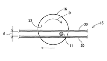
図3は、図1におけるIII−III断面図である。
丸棒部材11が平板部材30間に挿入され、丸棒部材11の端面31が砥石16の側面32に当接された状態で、スライド装置21が作動し、丸棒部材11は、上記搬送路12に沿ってスライドされる。
したがって、丸棒鋼11は、図3が示すように、その端面(31)が砥石16に押圧された状態で、回転されながら矢印34の方向(搬送路12の方向)にスライドされる。
【0021】
このように本実施形態では、砥石16の側面32は、平面に形成されているから、丸棒鋼11の端面31が砥石16の側面32と接触することによって、当該端面31は、平面に正確に研削される。また、研削中において、丸棒鋼11が砥石16の側面32に沿ってスライドされるから、丸棒鋼11の端面31に対する砥石16の摺動方向が常時変化する。したがって、丸棒鋼11の端面31が研削された後に、当該端面31の周縁部にいわゆるバリが生じることはない。
したがって、本実施形態に係る丸棒鋼の端面研削方法によれば、丸棒鋼11の端面31は、平面状態を保って均一に研削されるので、当該端面31は高精度に仕上げられ、その結果、製品としての丸棒鋼11は、高い品質が維持される。定量的には、シャーリング機によって丸棒鋼11が生成されたときの端面31の凹凸は、約3〜5mmであるが、上記砥石16によって仕上げられることによって、端面31の凹凸は、1mm以下となる。
【0022】
特に本実施形態では、丸棒鋼11は、中心軸回りに回転される。これにより、丸棒鋼11の端面31の周縁部は、砥石16に平均的に接触する。したがって、丸棒鋼11の端面31は、均一に研削され、高精度に仕上げられるという利点がある。
さらに、丸棒鋼11は、スライドベース15に沿ってスライドされるから、研削作業中において、丸棒鋼11が上下方向(スライド方向に直交する方向)に変位することがない。これにより、丸棒鋼11の端面31は、一層均一に研削され、より高精度に仕上げられる。
【0023】
【発明の効果】
以上のように本発明によれば、丸棒鋼の端面は、平面状態を保って均一に研削されるので、当該端面は高精度に仕上げられる。その結果、製品としての丸棒鋼は、高い品質が維持される。
【図面の簡単な説明】
【図1】図1は、本発明の一実施形態に係る丸棒鋼の端面研削方法が実施される研削装置の斜視図である。
【図2】図2は、図1におけるA−矢視図である。
【図3】図3は、図1におけるIII−III断面図である。
【図4】図4は、シャーリング機で切断された丸棒鋼の端部拡大図である。
【図5】図5は、図4におけるV−矢視図である。
【符号の説明】
10・・・研削装置
11・・・丸棒鋼
12・・・搬送路
13・・・グラインダ
14・・・ハンドリング装置
15・・・スライドベース
16・・・砥石
20・・・本体
21・・・スライド装置
22・・・挟持装置
26・・・挟持ローラ
27・・・挟持ローラ
28・・・回転軸
29・・・回転軸
30・・・平板部材
31・・・端面
32・・・側面[0001]
[Field of the Invention]
The present invention relates to a method for grinding an end face of a round steel bar.
[0002]
[Prior art]
The round bar steel is manufactured by cutting a long strip formed in advance. Long strips are generally cut with a shearing machine.
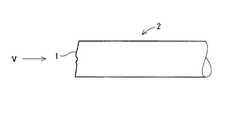
FIG. 4 is an enlarged view of an end of a round bar steel cut by a shearing machine, and FIG. 5 is a view taken along the line V- in FIG.
As shown in these figures, when the bar is cut with a shearing machine, the cut surface 1 is not a flat surface but a complicated three-dimensional shape. Therefore, in order to complete the round bar steel 2 as a product, the end surface of the round bar steel 2 needs to be ground and finished. This grinding finishing operation is usually performed by a grinder (see, for example, Patent Document 1 and Patent Document 2).
[0003]
[Patent Document 1]
JP-A-8-229788 [Patent Document 2]
JP-A-10-277893 [0004]
[Problems to be solved by the invention]
Generally, a grinder is provided with a circular grindstone, and this grindstone is rotated at a high speed with its center as a rotation center. Conventionally, the end face of the round steel bar is brought into contact with the peripheral surface of the rotating grindstone, whereby the end face is polished.
By the way, in order to improve the finishing accuracy of the end face of the round steel bar, it is necessary to finish the end face as much as possible.
However, since the end surface of the round steel bar is in contact with the peripheral surface of the circular grindstone, the end surface is formed into a curved surface having a curvature radius similar to that of the peripheral surface of the grindstone after being ground. This is a phenomenon that always occurs as long as the end face of the round steel bar comes into contact with the end face of the circular grindstone.
[0005]
Then, the objective of this invention is providing the end surface grinding method by which the end surface of round bar steel is finished in a perfect plane.
[0006]
[Means for Solving the Problems]
(1) Since the said objective is achieved, the end surface grinding method of the round bar steel which concerns on this application is applied to the said side surface, while the end surface of the cut round bar steel is pressed with the predetermined pressing force on the side surface of the rotating circular grindstone. It is characterized by being slid along.
According to this structure, when the side surface of the grindstone is formed in a flat surface, the end surface of the round bar steel comes into contact with the side surface of the grindstone, so that the end surface is ground into a flat surface. In addition, since round steel bar is slid along the side surface of the grindstone during grinding, so-called burrs do not occur at the peripheral edge of the end face after the end face is ground.
[0007]
(2) Moreover, it is preferable that the said round bar steel is rotated around a central axis.
In this configuration, since the peripheral edge of the end face of the round steel bar is in average contact with the grindstone, the end face is uniformly ground and finished with high accuracy.
(3) Furthermore, it is preferable that the round steel bar is slid along a slide base arranged along the sliding direction.
When the round bar steel is pressed against the rotating grindstone, the round bar steel tends to be pulled in the direction of the frictional force due to the frictional force generated between them. However, according to this configuration, even when the round bar steel is pulled by the frictional force, the round bar steel slide is defined by the slide base, so that the round bar steel is displaced in the direction of the frictional force. There is nothing. Thereby, the end surface of a round bar steel is ground more uniformly and finished with higher accuracy.
[0008]
DETAILED DESCRIPTION OF THE INVENTION
Hereinafter, the present invention will be described in detail based on preferred embodiments with appropriate reference to the drawings.
[0009]
FIG. 1 is a perspective view of a grinding apparatus for carrying out a method for grinding an end face of a round steel bar according to an embodiment of the present invention.
The grinding apparatus 10 is operated in a grinding finish line for the round bar steel 11 to grind the end surface 31 of the round bar steel 11 and finish it as a product.
[0010]
The grinding device 10 is disposed along the conveying path 12 of the grinding finish line, and includes a grinder 13, a handling device 14 for slidingly conveying the round steel bar 11 along the conveying path 12, and a slide of the round steel bar 11. And a slide base 15 for guiding the above.
[0011]
The grinder 13 includes a grindstone 16 and a drive motor 17. The drive motor 17 includes a rotating shaft 18, and the grindstone 16 is fixed to the rotating shaft 18. The grindstone 16 is generally provided for grinding steel materials. The grindstone 16 is formed in a circular shape as shown in the figure, and the rotary shaft 18 is connected to the center thereof. In the present embodiment, when the drive motor 17 is driven, the grindstone 16 rotates in the direction of the arrow 19. Of course, the direction of rotation of the grindstone 16 may be opposite to the direction of the arrow 19.
[0012]
The handling device 14 includes a main body 20 and a slide device 21. The main body 20 has a clamping device 22 which will be described later, and the round steel bar 11 as a workpiece is clamped by the clamping device 22.
The main body 20 is disposed on the slide device 21, and the slide device 21 runs along the rail 23. The rail 23 is formed along the transport path 12. Therefore, the main body 20 moves along the conveyance path 12 by operating the slide device 21.
The slide device 21 includes wheels 24. The wheel 24 is rotated by a drive motor (not shown), whereby the slide device 21 is self-propelled along the rail 23.
[0013]
The clamping device 22 includes a casing 25 and clamping rollers 26 and 27 arranged in the casing 25.
The sandwiching rollers 26 and 27 are provided with rotating shafts 28 and 29, respectively. The rotary shafts 28 and 29 are connected to a drive motor (not shown). This drive motor is also arranged in the casing 25. The rotary shafts 28 and 29 are rotatably supported by the casing 25 via bearings (not shown).
[0014]
When the drive motor is driven, the sandwiching rollers 26 and 27 are rotated. At this time, it is not necessary to drive the sandwiching rollers 26 and 27, respectively, and the other may be configured to be driven by driving one of the sandwiching rollers 26 and 27.
The sandwiching rollers 26 and 27 are disposed to face each other along the direction of the transport path 12 (that is, the longitudinal direction of the rail 23). The distance between each of the sandwiching rollers 26 and 27 corresponds to the outer diameter of the round steel bar 11 that is sandwiched by the sandwiching device 22.
[0015]
FIG. 2 is a view taken in the direction of arrow A in FIG. 1, and shows the relative positional relationship between the pinching roller 26 (27) and the round bar steel 11.
As shown in the figure, the clamping roller 26 (27) is inclined by a predetermined angle θ. Specifically, the central axis L of the rotating shaft 28 (29) of the pinching roller 26 (27) is inclined by an angle θ with respect to the horizontal direction (insertion direction of a round steel bar 11 described later). That is, as will be described in detail later, the round steel bar 11 is sandwiched between the pair of sandwiching rollers 26 and 27 arranged in such an inclination. The effect of the tilting of each of the sandwiching rollers 26 and 27 will be described later.
[0016]
In this embodiment, the slide base 15 is composed of a pair of flat plate members 30 made of a steel plate. As shown in FIG. 1, the flat plate member 30 is formed in an elongated strip shape, and is separated by a predetermined distance d along the vertical direction (direction perpendicular to the direction of the conveyance path 12). The predetermined distance d corresponds to the outer diameter of the round steel bar 11, and the round steel bar 11 is inserted between the flat plate members 30.
[0017]
In the present embodiment, the end surface of the round steel bar 11 is ground as follows.
The cut round steel bar 11 is conveyed along the arrow 33 in FIG. 1 and inserted into the handling device 14.
Specifically, the round steel bar 11 is inserted into a workpiece insertion port provided in the casing 25 and penetrates the casing 25. The sandwiching rollers 26 and 27 are disposed in the casing 25 as described above, and the round steel bar 11 is inserted between the sandwiching rollers 26 and 27.
[0018]
The slide device 21 of the handling device 14 is operated, and the main body 20 sandwiching the round steel bar 11 slides in the direction of the conveyance path 12. Thereby, the end surface 31 of the round steel bar 11 contacts the side surface 32 of the grindstone 16 as shown in FIG.
At this time, the sandwiching rollers 26 and 27 are rotated by the drive motor. However, since the sandwiching rollers 26 and 27 are inclined by an angle θ as shown in FIG. Slide (in the direction of arrow 33). Thereby, the end surface 31 of the round steel bar 11 is pressed against the side surface 32 of the grindstone 16 by a predetermined pressing force, specifically, 0.0980665 MPa (1 kgf / cm 2 ) to 0.980665 MPa (10 kgf / cm 2 ). become. Further, when the clamping rollers 26 and 27 are rotated, the round steel bar 11 is rotated around its central axis.
That is, the round steel bar 11 is rotated about the central axis, and the end surface 31 of the round steel bar 11 is pressed against the side surface 32 of the grindstone 16 with a predetermined pressing force.
[0019]
On the other hand, the round bar steel 11 is slid toward the grindstone 16 by rotating the clamping rollers 26 and 27. At this time, the round bar steel 11 is held by the slide base 15. Specifically, the round steel bar 11 is inserted between the pair of flat plate members 30 and is held by both flat plate members 30.
Specifically, since the distance d between the flat plate members 30 corresponds to the outer diameter of the round bar steel 11, the vertical bar displacement is regulated while the round bar steel 11 is inserted between the flat plate members 30. The displacement is possible only along the longitudinal direction of the flat plate member 30 (that is, the direction of the conveyance path 12).
[0020]
3 is a cross-sectional view taken along the line III-III in FIG.
The slide device 21 is operated in a state where the round bar member 11 is inserted between the flat plate members 30 and the end face 31 of the round bar member 11 is in contact with the side surface 32 of the grindstone 16, and the round bar member 11 12 is slid along.
Therefore, as shown in FIG. 3, the round steel bar 11 is slid in the direction of the arrow 34 (the direction of the conveyance path 12) while rotating with the end face (31) being pressed by the grindstone 16.
[0021]
Thus, in this embodiment, since the side surface 32 of the grindstone 16 is formed in a flat surface, when the end surface 31 of the round steel bar 11 comes into contact with the side surface 32 of the grindstone 16, the end surface 31 is accurately in a flat surface. To be ground. Further, during the grinding, the round bar 11 is slid along the side surface 32 of the grindstone 16, so that the sliding direction of the grindstone 16 with respect to the end surface 31 of the round bar 11 is constantly changed. Therefore, after the end surface 31 of the round steel bar 11 is ground, so-called burrs do not occur in the peripheral portion of the end surface 31.
Therefore, according to the end face grinding method of the round bar steel according to the present embodiment, the end face 31 of the round bar steel 11 is uniformly ground while maintaining a flat state, so that the end face 31 is finished with high accuracy. The quality of the round steel bar 11 as a product is maintained. Quantitatively, the unevenness of the end surface 31 when the round steel bar 11 is generated by the shearing machine is about 3 to 5 mm, but when the grinding wheel 16 is finished, the unevenness of the end surface 31 becomes 1 mm or less. .
[0022]
In particular, in this embodiment, the round steel bar 11 is rotated around the central axis. Thereby, the peripheral part of the end surface 31 of the round steel bar 11 contacts the grindstone 16 on average. Therefore, the end surface 31 of the round steel bar 11 is advantageously ground uniformly and finished with high accuracy.
Furthermore, since the round bar 11 is slid along the slide base 15, the round bar 11 is not displaced in the vertical direction (direction perpendicular to the sliding direction) during the grinding operation. Thereby, the end surface 31 of the round steel bar 11 is more uniformly ground and finished with higher accuracy.
[0023]
【The invention's effect】
As described above, according to the present invention, the end surface of the round bar steel is uniformly ground while maintaining a flat state, so that the end surface is finished with high accuracy. As a result, the quality of the round bar steel as a product is maintained.
[Brief description of the drawings]
FIG. 1 is a perspective view of a grinding apparatus in which a method for grinding an end face of a round bar steel according to an embodiment of the present invention is performed.
FIG. 2 is a view on arrow A in FIG.
FIG. 3 is a cross-sectional view taken along the line III-III in FIG.
FIG. 4 is an enlarged view of an end portion of a round bar steel cut by a shearing machine.
FIG. 5 is a V-arrow view in FIG. 4;
[Explanation of symbols]
DESCRIPTION OF SYMBOLS 10 ... Grinding device 11 ... Round steel bar 12 ... Conveyance path 13 ... Grinder 14 ... Handling device 15 ... Slide base 16 ... Grinding wheel 20 ... Main body 21 ... Slide Device 22: Holding device 26 ... Holding roller 27 ... Holding roller 28 ... Rotating shaft 29 ... Rotating shaft 30 ... Flat plate member 31 ... End surface 32 ... Side surface