JP2005011503A - System, apparatus, and method of assembling hard disk drive integrated lead suspension and arm/electronic cable via additional degree of freedom at tail termination and impedance adjusting thereof - Google Patents
System, apparatus, and method of assembling hard disk drive integrated lead suspension and arm/electronic cable via additional degree of freedom at tail termination and impedance adjusting thereof Download PDFInfo
- Publication number
- JP2005011503A JP2005011503A JP2004179290A JP2004179290A JP2005011503A JP 2005011503 A JP2005011503 A JP 2005011503A JP 2004179290 A JP2004179290 A JP 2004179290A JP 2004179290 A JP2004179290 A JP 2004179290A JP 2005011503 A JP2005011503 A JP 2005011503A
- Authority
- JP
- Japan
- Prior art keywords
- conductor
- tail
- support layer
- independently
- conductors
- Prior art date
- Legal status (The legal status is an assumption and is not a legal conclusion. Google has not performed a legal analysis and makes no representation as to the accuracy of the status listed.)
- Withdrawn
Links
Images


Classifications
-
- G—PHYSICS
- G11—INFORMATION STORAGE
- G11B—INFORMATION STORAGE BASED ON RELATIVE MOVEMENT BETWEEN RECORD CARRIER AND TRANSDUCER
- G11B5/00—Recording by magnetisation or demagnetisation of a record carrier; Reproducing by magnetic means; Record carriers therefor
- G11B5/48—Disposition or mounting of heads or head supports relative to record carriers ; arrangements of heads, e.g. for scanning the record carrier to increase the relative speed
- G11B5/4806—Disposition or mounting of heads or head supports relative to record carriers ; arrangements of heads, e.g. for scanning the record carrier to increase the relative speed specially adapted for disk drive assemblies, e.g. assembly prior to operation, hard or flexible disk drives
- G11B5/4853—Constructional details of the electrical connection between head and arm
-
- G—PHYSICS
- G11—INFORMATION STORAGE
- G11B—INFORMATION STORAGE BASED ON RELATIVE MOVEMENT BETWEEN RECORD CARRIER AND TRANSDUCER
- G11B5/00—Recording by magnetisation or demagnetisation of a record carrier; Reproducing by magnetic means; Record carriers therefor
- G11B5/48—Disposition or mounting of heads or head supports relative to record carriers ; arrangements of heads, e.g. for scanning the record carrier to increase the relative speed
- G11B5/4806—Disposition or mounting of heads or head supports relative to record carriers ; arrangements of heads, e.g. for scanning the record carrier to increase the relative speed specially adapted for disk drive assemblies, e.g. assembly prior to operation, hard or flexible disk drives
- G11B5/486—Disposition or mounting of heads or head supports relative to record carriers ; arrangements of heads, e.g. for scanning the record carrier to increase the relative speed specially adapted for disk drive assemblies, e.g. assembly prior to operation, hard or flexible disk drives with provision for mounting or arranging electrical conducting means or circuits on or along the arm assembly
Abstract
Description
本発明は、改良型ハード・ディスク・ドライブに関し、特に、ハード・ディスク・ドライブにおいてテール終端部で付加された自由度によって一体形リード・サスペンションとアーム・エレクトロニクス・ケーブルを組み立てる改良されたシステム、装置および方法に関する。 The present invention relates to an improved hard disk drive, and more particularly to an improved system and apparatus for assembling an integrated lead suspension and arm electronics cable with added flexibility at the tail end in a hard disk drive. And methods.
一般に、データ・アクセスや記憶装置は、磁気あるいは光記憶媒体上のデータを記憶する1個以上の記憶装置からなる。例えば磁気記憶装置は、直接アクセス記憶装置(DASD)、あるいはハード・ディスク・ドライブ(HDD)として知られディスクに関するローカル操作を管理する1個以上のディスク、およびディスク制御装置を備えている。通常、ハード・ディスクそれ自体は、アルミ合金あるいはガラスとセラミックとの混合素材でできており、磁気被膜で覆われている。標準的には、1乃至6枚のディスクが、数千毎分回転数(rpm)でディスク・ドライブ・モータによって回転する共通軸に垂直に積層されている。 In general, a data access or storage device consists of one or more storage devices that store data on magnetic or optical storage media. For example, a magnetic storage device includes one or more disks, known as direct access storage devices (DASD) or hard disk drives (HDD), that manage local operations on the disks, and a disk controller. Usually, the hard disk itself is made of an aluminum alloy or a mixed material of glass and ceramic and covered with a magnetic coating. Typically, 1 to 6 discs are stacked perpendicular to a common axis that is rotated by a disc drive motor at thousands of revolutions per minute (rpm).
標準的なHDDは、アクチュエータ・アセンブリも用いる。このアクチュエータは、磁気読取り/書込みヘッドを回転ディスク上の所望の位置に移動させ、その位置に情報を書き込みあるいはその位置からデータを読み取りする。ほとんどのHDDでは、この磁気読取り/書込みヘッドをスライダ上に取り付けている。通常、スライダは、ヘッドを機械的に支持し、ディスク駆動装置の他の部分との間の電気的接続に役立っている。このスライダは、回転ディスク面からの均一距離を維持するために、移動する空気の上を滑って移動するよう空気力学的形状をなしており、それによりヘッドが不用意にディスクに接触することを防いでいる。 Standard HDDs also use an actuator assembly. This actuator moves the magnetic read / write head to a desired position on the rotating disk and writes information to or reads data from that position. Most HDDs have this magnetic read / write head mounted on a slider. Usually, the slider mechanically supports the head and serves for electrical connection with other parts of the disk drive. This slider is aerodynamically shaped to slide over the moving air to maintain a uniform distance from the rotating disk surface, thereby preventing the head from inadvertently contacting the disk. It is preventing.
一般的にスライダは、ディスク・ドライブの動作中にディスク近傍で一定の高さでスライダが浮遊できるようにする空気ベアリング面(ABS)上に、突起状の空気力学的パターンを有して形成される。スライダは、各ディスクの各側面と関連しており、ディスク面上を浮遊している。各スライダは、ヘッド・ジンバル・アセンブリ(HGA)を形成するサスペンションに取り付けられる。次に、このHGAはヘッドの浮遊部全体を支持する反剛性アクチュエータ・アームに取り付けられる。いくつかの半剛性アームを組み合わせて、可変ユニットを形成してもよい。この可変ユニットには、リニア軸受けや回転枢動軸受けシステムが備えられている。 Generally, a slider is formed with a protruding aerodynamic pattern on an air bearing surface (ABS) that allows the slider to float at a constant height near the disk during disk drive operation. The The slider is associated with each side of each disk and floats on the disk surface. Each slider is attached to a suspension that forms a head gimbal assembly (HGA). The HGA is then attached to an anti-rigid actuator arm that supports the entire floating portion of the head. Several semi-rigid arms may be combined to form the variable unit. This variable unit is equipped with a linear bearing and a rotary pivot bearing system.
ヘッド・アーム・アセンブリは、しばしばボイス・コイル・モータ(VCM)と呼ばれる磁石/コイル機構を用いて線形移動、あるいは枢軸運動する。基板あるいは鋳型にVCMの固定子を装着し、その上にスピンドルも装着する。次にスピンドルと、アクチュエータVCMと、内部ろ過システムとからなるベース鋳型が、汚染物が封入したり、ディスク上のスライダ浮遊の信頼性に悪影響を与えたりしないようにカバーとシール・アセンブリで封入される。電流がモータに流れると、このVCMが印加電流に実質的に比例した力、またはトルクを生じる。したがってアームは電流の絶対値に実質的に比例する。読取り/書込みヘッドが所望のトラックに接近すると、アクチュエータに逆磁極信号が印加され、制動機として作動する信号を生じさせ、理想的には読取り/書込みヘッドが所望のトラックの上で直接停止する。 The head arm assembly moves linearly or pivots using a magnet / coil mechanism, often called a voice coil motor (VCM). A VCM stator is mounted on a substrate or a mold, and a spindle is mounted thereon. The base mold, consisting of the spindle, actuator VCM and internal filtration system, is then sealed with a cover and seal assembly to prevent contaminants from being trapped or adversely affecting the reliability of slider suspension on the disk. The When current flows through the motor, this VCM produces a force, or torque, that is substantially proportional to the applied current. Thus, the arm is substantially proportional to the absolute value of the current. As the read / write head approaches the desired track, a reverse pole signal is applied to the actuator, producing a signal that acts as a brake, ideally the read / write head stops directly on the desired track.
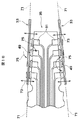
先行技術では、ディスク・ドライブのアーム・エレクトロニクス(A/E)ケーブルに一体型リード・サスペンション(ILS)の後端部を収納するような現行の好ましい方法で、半田接合が用いられている。この半田接合は、ILSテールとA/Eケーブルの間に形成された直角のすみ肉接合である。この接合形成に関する現行の技術は、例えばアルブレヒトらの米国特許第6,212,046号明細書で十分に文書化されている。現行の半田後端部は、嵌め合いA/E半田パッドの高さの相違に対処するILSテール上に平坦化させた半田パッドに依存する。この高さの相違は、A/Eケーブル上の半田パッドの製造上のばらつき、および/またはILSテール上の半田パッドのばらつきを原因とすることができる。A/E半田パッドを基礎にしたILSテールに角変位があると高さ相違を生じさせることもある。平坦化したパッドが、溶融半田の表面張力で略球面状態に熱せられる際に引っ張られると、ILSテール上の平坦化半田パッドの高さが増す。このようにして高さを増すと、ILSテール上の溶融半田がA/Eケーブル上の嵌め合い半田パッドに接触して接合形成できるようになる。現行工程はかなり頑健であるが、上述した原因による嵌め合いパッド間の、間隙が多すぎるため、関連の手直し比率が含まれている。この工程についてのその他の制限として、ILS製造は、十分な量の半田を確実に適用するための半田遮蔽工程に限られている点があげられる。 In the prior art, solder bonding is used in the current preferred way of housing the rear end of an integrated lead suspension (ILS) in a disk drive arm electronics (A / E) cable. This solder joint is a right-angle fillet joint formed between the ILS tail and the A / E cable. Current techniques for forming this junction are well documented, for example, in US Pat. No. 6,212,046 to Albrecht et al. The current solder back end relies on a solder pad that is flattened on the ILS tail that addresses the height difference of the mating A / E solder pads. This height difference can be due to manufacturing variations of solder pads on the A / E cable and / or variations of solder pads on the ILS tail. Angular displacement of the ILS tail based on A / E solder pads can cause height differences. When the planarized pad is pulled when heated to a substantially spherical state by the surface tension of the molten solder, the height of the planarized solder pad on the ILS tail increases. When the height is increased in this manner, the molten solder on the ILS tail can come into contact with the mating solder pads on the A / E cable to form a joint. The current process is fairly robust, but the associated rework ratio is included because there are too many gaps between mating pads due to the above-mentioned causes. Another limitation on this process is that ILS manufacturing is limited to a solder shielding process to ensure that a sufficient amount of solder is applied.
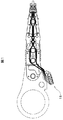
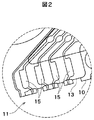
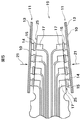
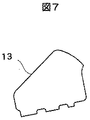
図1乃至図7を参照すると、ILSテール11に関する先行技術設計が示されている。ILSテール11には、銅パッド14(図5では8個例示されている)を支持するスチールでできた単一の大型ソリッド・プラットフォーム10(図6)が付されており、このパッドの間には、単一の大型固体絶縁物13(図7)や誘電体がある。遮蔽工程によって、半田パッド15が銅パッド14に応用される。理想的には、図4中で示したように、A/Eケーブル19上で、ILSテール11が半田パッド17(図3)と一致し、相互作用を起こし、90度のすみ肉接合を形成する。ILSテール11は水平になっており、A/Eケーブル19は垂直になっている。そして互いに90度の関係で配向されている。はじめにILSテール11が、A/Eケーブル19で形成された傾斜スロット23に挿入されるにつれ、互いに対向してバイアスを加えられ(すなわち曲げられ)、このまま制止する。解放されると、ILSテール11のハード・パッド15が装填され、すなわちA/Eケーブル19の半田パッド17に対向してバイアスが加えられる(矢印21参照)。
Referring to FIGS. 1-7, a prior art design for the
アルブレヒトらの米国特許第6,212,046号明細書に記載の通り、そして図5に示している通り、各ILSテール11はスチール層10、ポリイミド13、銅パッド14、平坦半田パッド15からなる。熱せられる際、半田パッド15は溶融して高さを増す。ILSテール11のばね荷重と一緒に半田パッド15の溶融状態が厚くなると、半田パッド15がILSテールとA/Eケーブル19との間のあるあらゆるギャップ、すなわち非嵌め合い状態を(一定限内で)許容できるようになる。先行技術では、一斉に全パッドのためにだけILSパッドおよびA/Eケーブルとの間の整合性がとられており、この整合性はテールのカンチレバーばね動作から得られる。このテールのラミネート厚全体が、テールに対するばねとして作用する。しかし、図5に示したように、ばね荷重21は、ILSテール11とA/Eケーブル19との間の全てのギャップ25や非嵌め合い状態を解消することはできない。1996年以来の生産で、上述したA/EケーブルにILSテールを終端させる上述の方法を使用してきたが、再加工あるいは「若干の手直し」の必要性が満たされず、今日でも未だにその必要性が残っている。例えば、パッド・レベルでは、再加工の発生率は比較的低い(最高で約1.5%)。しかしヘッド積層アセンブリ・レベルで再加工率を計算した場合、再加工率は高く、15%を超えることがある。
As described in US Pat. No. 6,212,046 to Albrecht et al. And as shown in FIG. 5, each
従来のより厚い半田の遮蔽工程に代わって、ILSパッド上でめっき工程を利用することは望ましくかつ好ましくさえあるが、このめっき工程は全体に半田パッドよりも薄いパッドを形成する。結果として、めっきパッドで生じる半田は、現行の好ましい遮蔽半田終端方法で必要とされまた発生する場合よりも少量となる。それゆえに、めっき工程の利点、つまり酸化しにくい、毒性物質の鉛(Pb)が除去される、半田合金がより幅広く選択できるなどの利点を実現することはできない。そのため、半田パッドをILSテールにめっきできるようにさせる、A/Eケーブルに対するILSテールを終端させる改善システム、装置、方法の必要性が望まれる。 Although it may be desirable and even preferable to utilize a plating process on the ILS pad instead of the conventional thicker solder shielding process, this plating process forms a pad that is thinner than the solder pad overall. As a result, less solder is generated at the plating pad than would be required and generated with current preferred shielded solder termination methods. Therefore, it is not possible to realize the advantages of the plating process, that is, the advantages of being hard to oxidize, removing the toxic substance lead (Pb), and selecting a wider range of solder alloys. Therefore, there is a need for an improved system, apparatus, and method for terminating ILS tails for A / E cables that allows solder pads to be plated on ILS tails.
アーム・エレクトロニクス(A/E)ケーブルに一体型リード・サスペンション(ILS)のテールを終端させるシステム、装置、方法の一実施例は、ILSテール上の半田パッドに2自由度を追加提供することにより、めっきした半田材をILSパッド上で使用できるようにする。自由度が高まったことで、半田接合を形成する半田パッドの個々の組み合せ間での整合性が高まる。本発明は、ILSテールでカンチレバーばねが動作することに加えて、各個別パッドがテールの平面から独立して出られるようにし、また軸周りを旋回できるようにした設計からなる。このように、各パッドはバット自体のジンバル機構を有しており、この機構は各種実施例を通じて提供されることができる。 One embodiment of a system, apparatus, and method for terminating an integrated lead suspension (ILS) tail on an arm electronics (A / E) cable is by providing two additional degrees of freedom for solder pads on the ILS tail. The plated solder material can be used on the ILS pad. The increased degree of freedom increases the consistency between individual combinations of solder pads that form a solder joint. In addition to the cantilever spring operating with the ILS tail, the present invention consists of a design that allows each individual pad to exit independently from the plane of the tail and pivot about its axis. Thus, each pad has its own gimbal mechanism, which can be provided through various embodiments.
本発明では、終端に達するためにパッド高を変える必要がないので、環境にやさしいめっき半田や無鉛合金を使用することもできる。しかし、従来の半田合金遮蔽が望まれる場合には、半田遮蔽加工を若干変更するだけで本発明を利用できる。例えば現在、半田遮蔽工程では、スチールが半田パッドの下に連なり、銅ILSパッドを支持している。半田はILSパッド上で遮蔽するように加工されるが、ILSサスペンションは全て未だパネル型である。このILSサスペンションとそのサスペンションのテールのパネルは、半田遮蔽マスクおよびプラテンとに対して位置を合わせる。半田遮蔽工程中、プラテンは、銅パッドを支持するためILSパッド域と一致させた隆起部分を必要とする。ILS銅パッドが半田遮蔽物との接触を失わないように、したがって、半田架橋を生じさせることが、この支持では必要とされる。通常、半田架橋は先行技術の半田マスク設計および工程を用いると発生する。 In the present invention, it is not necessary to change the pad height in order to reach the end, so that it is possible to use an environment-friendly plated solder or lead-free alloy. However, when the conventional solder alloy shielding is desired, the present invention can be used by slightly changing the solder shielding process. For example, at present, in the solder shielding process, steel continues below the solder pad and supports the copper ILS pad. The solder is processed to shield on the ILS pads, but all ILS suspensions are still panel type. The ILS suspension and the tail panel of the suspension are aligned with the solder shielding mask and the platen. During the solder shielding process, the platen requires a raised portion that matches the ILS pad area to support the copper pad. It is required for this support that the ILS copper pad not lose contact with the solder shield and therefore cause solder cross-linking. Typically, solder crosslinking occurs when using prior art solder mask designs and processes.
本発明に関する前述の、さらにその他の目的および利点は、特許請求の範囲および図面を用いて、本発明を実施するための最良の形態についての次の詳細な記載を考慮すれば、当業者らに明らかとなろう。 The foregoing and other objects and advantages of the invention will become apparent to those skilled in the art upon consideration of the following detailed description of the best mode for carrying out the invention using the claims and the drawings. It will be clear.
本発明によれば、ILSパッドとA/Eケーブルとの間の整合性が、個々のパッドについて得られているので、ILSテールのばね荷重によりあらゆる間隙および非嵌め合い状態に対応できる。その結果、再加工あるいは「若干の手直し」の必要性が事実上なくなる。 According to the present invention, the consistency between the ILS pad and the A / E cable is obtained for the individual pads, so that any gaps and unmated states can be accommodated by the spring load of the ILS tail. As a result, there is virtually no need for rework or “slight rework”.
本発明の特徴や利点その他明らかとなる事項が達成され、理解できるように、本明細書の一部をなす添付の図面中に示された実施例を参照することで、上記に主に要約された発明のより特定を得ることができる。しかしこれらの図は、本発明の一実施例を示したに過ぎず、したがって本発明が他の効果的な実施例と同様に適用される範囲を制限するものではない点に留意されたい。 In order that the features and advantages of the present invention as well as other obvious matters may be achieved and understood, it will primarily be summarized above by reference to the embodiments illustrated in the accompanying drawings, which form a part of this specification. More specifics of the invention can be obtained. It should be noted, however, that these figures show only one embodiment of the present invention and therefore do not limit the scope to which the present invention can be applied as well as other effective embodiments.
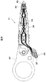
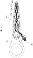
図8乃至図11および18を参照し、ハード・ディスク・ドライブ用アーム・エレクトロニクス・ケーブル35(図18)に一体型リード・サスペンション39のテール33を終端させるシステム、方法、装置の一実施例を示す。この実施例では、ヘッド・ジンバル・アセンブリ31は、単一装着アームなど取り付け装置37に装着された一体型リード・サスペンション39や、一体型リード・サスペンション39に装着された読取り/書込みヘッド41を備えている。取り付け装置37は、通常当業者間で一般に知られる取り付け機構の別タイプを構成してもよい。ヘッド・ジンバル・アセンブリ31には、読取り/書込みヘッド41、テール33、複数の導体43(4個示されている)などが含まれる。各導体43は、読取り/書込みヘッド41から延びてこれらと電気的に内部接続している第一端部45と、軸49を持つ第二端部47を有する。この導体43の第二端部47をテール33が支持する。
With reference to FIGS. 8-11 and 18, one embodiment of a system, method and apparatus for terminating a
図9乃至図11に示すとおり、テール33はさらにステンレス鋼から形成された支持層51を形成する。本発明に従って、支持層51は、導体43の第二端部47がこの導体43の第二端部47の他端について独立して動けるように支持層の中に形成した少なくとも1個の開口53を有する。図9および図10の実施例において、支持層51a中の少なくとも1個の開口53aは、導体43の第二端部47全ての独立した動きを許容する一般的には矩形の単一開口をなす。
As shown in FIGS. 9 to 11, the
一つの代替実施例(図12)では、支持層51b中の少なくとも1個の開口53bが、複数(4個示した)の小型で、一般的には矩形の開口または空隙からなり、それぞれが導体43にある第二端部47の一つの独立した動きを許容する。テール33は、導体43部分と支持層51の接触を防ぐようその二つの間に形成された(標準的にはポリイミドまたはその他の絶縁体もしくは誘電体から形成された)絶縁層61も有する。絶縁層61の2つの実施例が図に示されている。図11の実施例では、絶縁層61aは固体である。図13の実施例では、絶縁層61bには、概ね矩形の空隙63と、この空隙63に形成された複数の小さな概ね矩形の絶縁パッド65とが含まれている。尚、この空隙63は、支持層51および導体43の第二端部47間の接触を防ぐためのものである。テール33、導体43、支持層51、絶縁層61のこれら実施例は異なる組み合せで結合してもよい。
In one alternative embodiment (FIG. 12), at least one
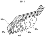
本発明の別の代替実施例(図14乃至図17)では、ヘッド・ジンバル・アセンブリ31cに、読取り/書込みヘッド41cが取り付けられており、(上述の)取り付け装置37cに装着された、テール33cおよび複数の導体43cを有する一体型リード・サスペンション39cを備えている。導体43cの各々は読取り/書込みヘッド41cから延びて電気的に内部接続された第一端部45cと、軸49cを持つ第二端部47cを有する。テール33cは導体43cの第二端部47cを支持する。この実施例において、支持層51c内の少なくとも1個の開口53cは、導体43cの第二端部47c全ての形状に輪郭付けられ、導体43cの第二端部47c全ての独立運動を許容する複数の開口53cを画成する、単一の非対称空隙である。この支持層51cは、複数のフィンガ55も有しており、各フィンガが導体43cの第二端部47cのそれぞれ1個を追加的に支持する複数の開口53cのうち1つの中に延びている。絶縁層61cは、種々の実施例を構成することができ、フィンガ55を含む前記導体43cの少なくとも一部と前記支持層51cの接触を防ぐため、その二つの間に位置付けられている。
In another alternative embodiment of the present invention (FIGS. 14-17), a tail /
図14乃至図17は、終端パッドの下にジンバルを作る上で好ましいアプローチも表してもいる。カンチレバー・フィンガ55(図16)はスチール層から形成されており、導体トレース47c(図15)の幅と配線とをなぞっている。このアプローチは、ジンバルのばね剛性を調整する際の許容範囲がILSテール33c全体のばね剛性よりも小さくなることを見越して考慮されたものである。また、このアプローチには、トレースの対接地電気容量を、トレースの長さにわたり、また終端パッドの下で一定にする別の利点も含まれている。今日のILS設計では、終端パッドの表面積が増加すると、インピーダンスを局所的に大きく増加させるような対接地電気容量の増加が起こる。そして、このことが2GB/秒を大幅に超える、データ転送率の増加にとって障害となる。ゆえに、フィンガ55はトレース47cについて「調整したインピーダンス」である。
FIGS. 14-17 also represent a preferred approach for making a gimbal under the termination pad. The cantilever finger 55 (FIG. 16) is formed from a steel layer and traces the width and wiring of the
作動する際には、本発明の種々の実施例は実質的に同じ方法で作動する。一体型リード・サスペンション39の支持層51が面71を画成し(図18)、導体43の第二端部47が、導体43の第二端部47の他方について独立して、矢印73によって示されたように、面71から自在に出る。更に具体的には、導体43の第二端部47が、導体43の第二端部47の他方について独立して曲がる(再び矢印73参照)ようになされ、あるいは曲がることができる。加えて、導体の第二端部が導体43の第二端部47の他方について独立して導体のそれぞれの軸49周りを自在に旋回する(矢印75参照)。次に、導体43の各第二端部47が、導体43の第二端部47の他方について少なくとも2自由度で自在に二方向角移動する。いずれの実施例も、ヘッド・ジンバル・アセンブリを装着する際に用いられる装着装置から独立している。
In operation, the various embodiments of the present invention operate in substantially the same manner. The
本発明の方法では、テール33を有するヘッド・ジンバル・アセンブリ31やそれぞれ軸49を有する端部47からなる複数の導体43を提供することで、一体型リード・サスペンション39を終端させる。この方法は、テール33を有する導体43の端部47を支持することからなり、導体43の端部47は導体43の端部47の他方について独立して自在に動く。また、複数の導体43および端部47に対応する複数のパッド81を有するアーム・エレクトロニクス・ケーブル35(図18)に向けて(例えば、支持層51を介したばね動作によって)テール33にバイアスをかける方法からもなる。さらに、各端部47を独立して動かしてパッド81それぞれと接触させ、パッド81のそれぞれに対する端部47を終端させる方法とからなる。
The method of the present invention terminates the
上述したように、本発明は、導体43の端部47の他端についてテール33により画成された面71から導体43の端部47を曲げられるようにすることからも構成される。さらに、本発明は、前記導体43の端部47の他方について独立して導体のそれぞれの軸49周りの導体43の端部47を旋回することからなる。したがって、導体43の端部47が、導体43の端部の他方について少なくとも2自由度で二方向角移動する。図14乃至図17の実施例で示されるように、この方法は、導体43cの端部47c全ての形状に輪郭が描かれ、導体43cの端部47c全ての独立運動を許容する複数の開口53cを画成する空隙53cを備えたテール33と、それぞれが導体43cの端部47cのそれぞれ1個を追加的に支持する複数の開口53cのうち、1つの中に延びている複数のフィンガ55とを提供することで構成されていてもよい。
As described above, the present invention is also configured by bending the
図19を参照すると、コンピュータ・システム用の磁気ハード・ディスク・ファイルやドライブ111からなる情報記憶装置の一実施例の概略図が示されている。本発明は、下記のようにドライブ111に最初から組み込んでもよい。ドライブ111には、少なくとも1個の磁気ディスク115からなるディスク・パック・アセンブリを含む外部筐体あるいはベース113が含まれる。ディスク115は、中央駆動ハブアセンブリ117を有するスピンドル・モータ・アセンブリにより回転する。アクチュエータ121は、複数の平行アクチュエータ・アーム125(1個図示した)からなり、これら125はピボット・アセンブリ123まわりのベース113に枢動可能に装着された櫛形状をなしている。また制御装置119が、ディスク115に対するアーム125の櫛を選択的に動かすベース113に装着されてもいる。
Referring to FIG. 19, a schematic diagram of one embodiment of an information storage device comprising a magnetic hard disk file for a computer system and a
実施例に示したように、各アームから、少なくとも1個のカンチレバー・ロード・ビームおよびサスペンション127が延びている。磁気読取り/書込みトランスデューサあるいはヘッドがスライダ129に装着され、各サスペンション127に柔軟に取り付けられた湾曲部に固定される。読取り/書込みヘッドは、ディスク115を相手に、データの磁気的な読み書きを行う。ヘッド・ジンバル・アセンブリは、ヘッドとスライダ129を一体化したもので、サスペンション127に取り付けられている。通常、スライダ129はサスペンション127の端部に結合されている。ヘッドは標準的にはピコサイズ(約1250×1000×300ミクロン)であり、セラミックあるいは金属間物質から形成される。ヘッドはまたナノサイズ(約850×700×230ミクロン)としてもよく、サスペンション127によりディスク115面(2から10グラムの範囲で)に事前に装填されている。
As shown in the example, at least one cantilever load beam and
サスペンション127にはばねの性質があり、ディスク115に対してスライダ129の空気ベアリング面にバイアスをかけるか、それらを付勢してスライダ129とディスク面との間に空気ベアリング膜を生成する。従来のボイス・コイル・モータ磁石アセンブリ134(最上部ポール、図示せず)内に収容されたボイス・コイル133は、ヘッド・ジンバル・アセンブリに対向するアーム125にも装着されている。制御装置119によって動くアクチュエータ121(矢印135により示された)はディスク115上のトラックを径方向に横切り、ヘッドがそれぞれのターゲット・トラックに落ち着くまで、ヘッド・ジンバル・アセンブリを移動する。ドライブ111が多重独立型アクチュエータ(図示せず)を用いてアームが互いに独立して動くのでない限り、ヘッド・ジンバル・アセンブリは従来の方法で動作し、常に一斉に移動する。
The
本発明には、先行技術より有利な点が数多くある。本発明は、ILSテールとA/Eケーブルの間のあらゆる間隙や非嵌め合い状態を許容し続ける一方で、ILSテール上での厚い半田遮蔽パッドの必要性を解消している。ILSパッドとA/Eケーブルとの間の整合性が、個々のパッドについて得られているので、ILSテールのばね荷重によりあらゆる間隙および非嵌め合い状態に対応できる。その結果、再加工あるいは「若干の手直し」の必要性が事実上なくなる。本発明は、従来の厚い半田の遮蔽工程の代わりにILSパッドを形成するよう、薄いプレート工程を用いるようにした。めっき工程では、標準的に半田パッドよりも薄いパッドが形成される、酸化しにくい、毒性鉛が除去される、半田合金がより幅広く選択できるなど新たな利点がもたらされた。 The present invention has many advantages over the prior art. The present invention eliminates the need for thick solder shielding pads on the ILS tail while continuing to allow any gaps and unmated conditions between the ILS tail and the A / E cable. Since the consistency between the ILS pad and the A / E cable is obtained for each individual pad, the ILS tail spring load can accommodate any gaps and unmated conditions. As a result, there is virtually no need for rework or “slight rework”. The present invention uses a thin plate process to form an ILS pad instead of the conventional thick solder shielding process. In the plating process, new advantages such as the formation of a thinner pad than the solder pad, resistance to oxidation, removal of toxic lead, and a wider selection of solder alloys are provided.
A/EケーブルにILSを終端させる、本発明のシステム、装置、方法は、新たに2自由度をILSテール上の半田パッドに提供することで、めっき半田材をILSパッド上で使用するようにした構成である。自由度が高まったおかげで、半田接合を形成する半田パッドの個々の組み合せ間の整合性が増す。本発明は、ILSテールのカンチレバーばね動作に加えて、各個別パッドが独立してテール面から動けるようにし、軸まわりを旋回できるようにしている。このように、各パッドはそれ自身のジンバル構成を有しており、これは種々の実施例を介して提供可能である。 The system, apparatus, and method of the present invention that terminates the ILS on the A / E cable provides a new two degree of freedom to the solder pad on the ILS tail so that the plated solder material is used on the ILS pad. This is the configuration. Thanks to the increased freedom, the consistency between the individual combinations of solder pads forming the solder joints is increased. In addition to the ILS tail cantilever spring action, the present invention allows each individual pad to move independently from the tail surface and pivot about its axis. Thus, each pad has its own gimbal configuration, which can be provided through various embodiments.
本発明では、終端を達成する際に半田パッドの高さを変化させる必要はない。しかし、従来の半田合金の遮蔽加工が望まれる場合、本発明は、半田遮蔽加工を若干変えるだけで利用することができる。例えば現行では、半田遮蔽工程中、半田パッドの下にある連続的スチールが銅ILSパッドを支持している。半田はILSパッド上で遮蔽するように加工されるが、まだILSサスペンションは全て未だにパネル型である。ILSサスペンションのパネルおよびそれらのテールは、半田遮蔽マスクに配置され、プラテンに位置合わせされている。本発明のプラテンは、半田遮蔽工程中銅パッドを支持するためILSパッド域と一致させた隆起部分を必要とする。ILS銅パッドが半田遮蔽物との接触を失わないように、したがって、半田架橋を生じさせることが、この支持では必要とされる。 In the present invention, it is not necessary to change the height of the solder pad when achieving termination. However, in the case where a conventional solder alloy shielding process is desired, the present invention can be used by slightly changing the solder shielding process. For example, currently, during the solder shielding process, a continuous steel under the solder pad supports the copper ILS pad. Although the solder is processed to shield on the ILS pads, all ILS suspensions are still panel type. The panels of the ILS suspension and their tails are placed on the solder shielding mask and aligned with the platen. The platen of the present invention requires a raised portion that matches the ILS pad area to support the copper pad during the solder shielding process. It is required for this support that the ILS copper pad not lose contact with the solder shield and therefore cause solder cross-linking.
本発明は、そのいくつかの形式で示したか記述したに過ぎないが、それらには限定されず、本発明の範囲を逸脱しない限りにおいて種々の変更の余地があることは、当業者には明白なはずである。 It will be apparent to those skilled in the art that the present invention has been shown or described in several forms thereof, but is not limited thereto and that there are various modifications without departing from the scope of the present invention. It should be.
31,31c…ヘッド・ジンバル・アセンブリ、
33,33c…テール、
35…アーム・エレクトロニクス・ケーブル、
37,37c…アーム取り付け装置、
39,39c…一体型リード・サスペンション、
41,41c…読取り/書込みヘッド、
43,43c…導体、
45,45c…第一端部、
47,47c…第二端部、
49,49c…軸、
51,51a,51b,51c…支持層、
53,53a,53b,53c…開口、
55…フィンガ、
61,61a,61b,61c…絶縁層、
63…空隙、
65…絶縁パッド、
71…面、
81…パッド、
111…ハード・ディスク・ドライブ、
115…磁気ディスク、
113…ベース、
117…スピンドル・モータ・アセンブリ、
119…制御装置、
121…アクチュエータ、
123…ピボット・アセンブリ、
125…アクチュエータ・アーム、
127…サスペンション
129…スライダ。
31, 31c ... head gimbal assembly,
33, 33c ... Tail,
35 ... Arm Electronics Cable,
37, 37c ... Arm mounting device,
39, 39c: Integrated lead suspension,
41, 41c ... read / write head,
43, 43c ... conductor,
45, 45c ... first end,
47, 47c ... second end,
49, 49c ... axis,
51, 51a, 51b, 51c ... support layer,
53, 53a, 53b, 53c ... opening,
55 ... Finger,
61, 61a, 61b, 61c ... insulating layer,
63 ... void,
65. Insulating pad,
71 ...
81 ... Pad,
111 ... Hard disk drive,
115 ... magnetic disk,
113 ... Base,
117 ... spindle motor assembly,
119 ... Control device,
121 ... Actuator,
123 ... Pivot assembly,
125 ... Actuator arm,
127 ...
Claims (32)
前記導体の第二端部の他方について、内部で前記導体の第二端部が独立して動けるように形成された少なくとも1個の開口を有する支持層と、
前記導体の一部と前記支持層との間に接触を防ぐために形成された絶縁層と、を有することを特徴とする一体型リード・サスペンション。 A plurality of conductors each having a first end extending from the head region and a second end having an axis, the tail supporting the second end of the conductor, the tail further comprising:
A support layer having at least one opening formed so that the second end of the conductor can independently move inside the second end of the conductor;
An integrated lead suspension comprising: an insulating layer formed to prevent contact between a part of the conductor and the support layer.
前記取り付け装置に装着され、読取り/書込みヘッドと、テールと、各々が前記読取り/書込みヘッドと電気的に内部接続されかつ前記読取り/書込みヘッドから延びた第一端部と、軸を有する第二端部とを備えた複数の導体とを含み、前記テールが前記導体の前記第二端を支持する一体型リード・サスペンションと、を有し、前記テールはさらに、
前記導体の第二端部の他方について、内部で前記導体の第二端部が独立して動けるように形成された少なくとも1個の開口を有する支持層と、
前記導体の一部と前記支持層との間に接触を防ぐために形成された絶縁層と、を有することを特徴とするヘッド・ジンバル・アセンブリ。 A mounting device;
A second end mounted to the mounting apparatus, having a read / write head, a tail, a first end each electrically interconnected with and extending from the read / write head, and a shaft; A plurality of conductors with ends, wherein the tail has an integral lead suspension that supports the second end of the conductors, the tail further comprising:
A support layer having at least one opening formed so that the second end of the conductor can independently move inside the second end of the conductor;
A head gimbal assembly comprising: an insulating layer formed to prevent contact between a part of the conductor and the support layer.
前記筐体に装着され前記筐体に対して回転可能である媒体記憶ディスクを備えたディスク・パック・アセンブリと、
前記筐体に可動に装着され一体型リード・サスペンションと、読取り/書込みヘッドと、前記一体型リード・サスペンションから延びたテールと、各々が前記読取り/書込みヘッドから延びて電気的に内部接続された第一端部並びに軸を持つ第二端部を有する複数の導体とを含むヘッド・ジンバル・アセンブリとを有し、前記テールは前記導体の第二端部を支持するアクチュエータと、を有し、前記テールはさらに、
面を画成し、前記導体の前記第二端部の各々の独立した二方向角移動を許容する複数の開口を画成する前記導体の第二端部全ての形状に輪郭を描く非対称な空隙を有しており、前記導体の第二端部の各々が、前記導体の前記第二端部の他方について少なくとも2自由度を有するような支持層と、
前記導体の一部と前記支持層との間に接触を防ぐために形成された絶縁層と、を有することを特徴とするハード・ディスク・ドライブ。 A housing,
A disk pack assembly comprising a media storage disk mounted on the housing and rotatable relative to the housing;
An integrated read suspension, a read / write head, a tail extending from the integrated read suspension, each extending from the read / write head and electrically interconnected are movably mounted on the housing. A head gimbal assembly including a first end and a plurality of conductors having a second end having an axis, and the tail includes an actuator that supports the second end of the conductor; The tail further includes
An asymmetric air gap that outlines the shape of all of the second ends of the conductor that defines a plurality of openings that define a plane and allow independent bi-directional angular movement of each of the second ends of the conductor And wherein each of the second ends of the conductor has at least two degrees of freedom with respect to the other of the second ends of the conductor;
A hard disk drive comprising: an insulating layer formed to prevent contact between a part of the conductor and the support layer.
(b)前記テールを持つ導体の端部を、該導体の端部が当該導体の端部の他方について独立して自在に動くように支持するステップと、
(c)前記複数の導体に対応する複数のパッドを有するアーム・エレクトロニクス・ケーブルに向かって前記テールにバイアスをかけるステップと、
(d)前記導体の各端部を独立して動かし、前記パッドそれぞれと接触させるステップと、
(e)前記パッドのそれぞれに対する前記導体の端部を終端させるステップと、
を含むことを特徴とする一体型リード・サスペンションを終端させる方法。 (a) providing an integrated lead suspension with a plurality of conductors having tails and ends each having an axis;
(b) supporting an end portion of the conductor having the tail so that the end portion of the conductor can freely move independently of the other end of the conductor;
(c) biasing the tail toward an arm electronics cable having a plurality of pads corresponding to the plurality of conductors;
(d) independently moving each end of the conductor to contact each of the pads;
(e) terminating the end of the conductor for each of the pads;
A method of terminating an integrated lead suspension comprising:
Applications Claiming Priority (1)
| Application Number | Priority Date | Filing Date | Title |
|---|---|---|---|
| US10/600,638 US7110222B2 (en) | 2003-06-20 | 2003-06-20 | System and apparatus for assembling hard disk drive integrated lead suspensions to arm electronics cables via additional degrees of freedom at the tail termination and impedance grooming thereof |
Publications (2)
| Publication Number | Publication Date |
|---|---|
| JP2005011503A true JP2005011503A (en) | 2005-01-13 |
| JP2005011503A5 JP2005011503A5 (en) | 2007-07-26 |
Family
ID=33517802
Family Applications (1)
| Application Number | Title | Priority Date | Filing Date |
|---|---|---|---|
| JP2004179290A Withdrawn JP2005011503A (en) | 2003-06-20 | 2004-06-17 | System, apparatus, and method of assembling hard disk drive integrated lead suspension and arm/electronic cable via additional degree of freedom at tail termination and impedance adjusting thereof |
Country Status (3)
| Country | Link |
|---|---|
| US (1) | US7110222B2 (en) |
| JP (1) | JP2005011503A (en) |
| CN (1) | CN100454429C (en) |
Families Citing this family (22)
| Publication number | Priority date | Publication date | Assignee | Title |
|---|---|---|---|---|
| JP2006049751A (en) * | 2004-08-09 | 2006-02-16 | Hitachi Global Storage Technologies Netherlands Bv | Magnetic disk device, wiring connection structure therefor, and terminal structure |
| US7344060B2 (en) * | 2004-09-27 | 2008-03-18 | Hitachi Global Storage Technologies Netherlands, B.V. | Apparatus and method for aligning solder pads during head gimbal assembly soldering |
| US7414814B1 (en) | 2005-04-28 | 2008-08-19 | Western Digital Technologies, Inc. | Disk drives, head stack, head gimbal and suspension assemblies having a compliant suspension tail design for solder reflow |
| US8395866B1 (en) | 2005-09-09 | 2013-03-12 | Magnecomp Corporation | Resilient flying lead and terminus for disk drive suspension |
| US8553364B1 (en) | 2005-09-09 | 2013-10-08 | Magnecomp Corporation | Low impedance, high bandwidth disk drive suspension circuit |
| US7538981B1 (en) * | 2006-05-10 | 2009-05-26 | Western Digital Technologies, Inc. | Head stack assembly including a flexure with radially inward fingers projecting into a flexure tail hole, and method of coupling the flexure to a flex cable |
| US7852604B2 (en) * | 2006-06-27 | 2010-12-14 | Seagate Technology Llc | Slider suspension assembly including a flex circuit arm with a flex circuit tab attached to a gimbal spring arm |
| JP2008172012A (en) * | 2007-01-11 | 2008-07-24 | Nitto Denko Corp | Suspension substrate with circuit |
| US8213124B2 (en) * | 2007-04-04 | 2012-07-03 | Hitachi Global Storage Technologies, Netherlands B.V. | Flex cable assembly for robust right angle interconnect |
| JP2008300594A (en) * | 2007-05-31 | 2008-12-11 | Fujitsu Ltd | Electronic equipment, and manufacturing method of electronic equipment |
| US8004798B1 (en) | 2008-03-31 | 2011-08-23 | Magnecomp Corporation | High bandwidth flexure for hard disk drives |
| US9324346B1 (en) | 2008-08-20 | 2016-04-26 | Western Digital Technologies, Inc. | Head stack assembly with a flexible printed circuit having a mouth centered between arms |
| US8279560B1 (en) | 2009-03-04 | 2012-10-02 | Western Digital Technologies, Inc. | Head stack assembly with suspension tail bond alignment by solder pin |
| US8068314B1 (en) | 2009-03-18 | 2011-11-29 | Western Digital Technologies, Inc. | Head stack assembly with suspension tails extending into interfering slits in a flexible printed circuit |
| JP4528869B1 (en) * | 2009-05-22 | 2010-08-25 | 株式会社東芝 | Head gimbal assembly and disk device provided with the same |
| US8587901B1 (en) | 2009-12-30 | 2013-11-19 | Western Digital (Fremont), Llc | Magnetic recording head slider comprising bond pad having a probe contact area and a solder contact area |
| JP6016047B2 (en) * | 2011-06-15 | 2016-10-26 | 大日本印刷株式会社 | Suspension board, suspension, suspension with head and hard disk drive |
| US8611052B1 (en) * | 2012-03-27 | 2013-12-17 | Western Digital Technologies, Inc. | Systems and methods for aligning components of a head stack assembly of a hard disk drive |
| US9330695B1 (en) | 2013-12-10 | 2016-05-03 | Western Digital Technologies, Inc. | Disk drive head suspension tail with a noble metal layer disposed on a plurality of structural backing islands |
| US8934199B1 (en) | 2014-03-31 | 2015-01-13 | Western Digital Technologies, Inc. | Disk drive head suspension tail with bond pad edge alignment features |
| US9236070B1 (en) * | 2014-08-18 | 2016-01-12 | Nitto Denko Corporation | Dual opposing cantilever pads of suspension flexure |
| JP6588328B2 (en) * | 2015-12-21 | 2019-10-09 | 日本発條株式会社 | Method for manufacturing printed circuit board |
Family Cites Families (6)
| Publication number | Priority date | Publication date | Assignee | Title |
|---|---|---|---|---|
| US5631786A (en) * | 1994-05-19 | 1997-05-20 | International Business Machines Corporation | Termination pad manipulator for a laminated suspension in a data storage system |
| US6477014B1 (en) * | 1994-05-19 | 2002-11-05 | International Business Machines Corporation | Multilayered suspension with conductive lead structure extending beyond base layer |
| US6212046B1 (en) * | 1997-09-26 | 2001-04-03 | International Business Machines Corporation | Arm assembly for a disk drive device and a method for fabricating the same |
| JP2001084544A (en) * | 1999-09-16 | 2001-03-30 | Fujitsu Ltd | Head assembly suspension and head assembly |
| US6543673B2 (en) * | 2000-11-06 | 2003-04-08 | Seagate Technology Llc | Dissolving shunt connection system for ESD sensitive components |
| JP4312968B2 (en) * | 2001-02-08 | 2009-08-12 | 日本発條株式会社 | Wiring member for disk drive suspension |
-
2003
- 2003-06-20 US US10/600,638 patent/US7110222B2/en not_active Expired - Lifetime
-
2004
- 2004-06-15 CN CNB200410059315XA patent/CN100454429C/en active Active
- 2004-06-17 JP JP2004179290A patent/JP2005011503A/en not_active Withdrawn
Also Published As
| Publication number | Publication date |
|---|---|
| US7110222B2 (en) | 2006-09-19 |
| US20040257708A1 (en) | 2004-12-23 |
| CN100454429C (en) | 2009-01-21 |
| CN1574031A (en) | 2005-02-02 |
Similar Documents
| Publication | Publication Date | Title |
|---|---|---|
| JP2005011503A (en) | System, apparatus, and method of assembling hard disk drive integrated lead suspension and arm/electronic cable via additional degree of freedom at tail termination and impedance adjusting thereof | |
| US7414814B1 (en) | Disk drives, head stack, head gimbal and suspension assemblies having a compliant suspension tail design for solder reflow | |
| US6522504B1 (en) | Head stack assembly and disk drive using a reversed direction head gimbal assembly | |
| US7315435B1 (en) | Disk drives, head stack, head gimbal and suspension assemblies having positional conductive features | |
| US7403357B1 (en) | Disk drive flexure assembly with a plurality of support bond pad apertures with a bond pad disposed over a bond pad support and part of each support bond pad aperture | |
| JP3965233B2 (en) | Head suspension assembly and data recording disk drive | |
| US7006330B1 (en) | Head stack assembly including a ground conductive pad for grounding a slider to a gimbal | |
| US7006331B1 (en) | Head gimbal assembly including a trace suspension assembly backing layer with a conductive layer formed upon a gimbal having a lower oxidation rate | |
| US7315436B1 (en) | Suspension assembly with a shape memory actuator coupled to a gimbal | |
| US7869164B2 (en) | Flexible printed circuit board having crack-preventing features between static and dynamic regions, and hard disk drive employing the same | |
| US6833978B2 (en) | Micro-actuator integrated lead suspension head terminations | |
| US5889636A (en) | Electrical connection for slider/suspension assembly | |
| JP4927425B2 (en) | Suspension, head gimbal assembly and disk drive using the same | |
| US8213121B2 (en) | HGA suspension pad barrier for elimination of solder bridging defect | |
| JP5979768B2 (en) | Features of a two-stage microactuator flexure to minimize electrical shorts | |
| JPH103633A (en) | Spacer device for slider/suspension and space control method | |
| US6747849B1 (en) | High performance suspension with reduced flow-induced vibration | |
| US6219202B1 (en) | Slider suspension assembly and method for attaching a slider to a suspension in a data-recording disk file including a flexible integrated cable having an aperture therein for permitting electrical contact | |
| JP2012123896A (en) | Integrated lead suspension (ils) for use with dual stage actuator (dsa) | |
| US11900974B2 (en) | Hard drive flexure including a trace overlapping a base layer feature | |
| US20110090601A1 (en) | Suspension with flexure tail and manufacturing method thereof, head stack assembly and disk drive unit with the same | |
| JP7300532B2 (en) | Hard disk drive suspension tail with narrowing tip | |
| US9025283B1 (en) | Laminated suspension flexure with open polyimide base | |
| KR100272874B1 (en) | A head support arm of disk driver apparatus | |
| JP2003091953A (en) | Slider assembly |
Legal Events
| Date | Code | Title | Description |
|---|---|---|---|
| A521 | Written amendment |
Free format text: JAPANESE INTERMEDIATE CODE: A523 Effective date: 20070611 |
|
| A621 | Written request for application examination |
Free format text: JAPANESE INTERMEDIATE CODE: A621 Effective date: 20070611 |
|
| RD02 | Notification of acceptance of power of attorney |
Free format text: JAPANESE INTERMEDIATE CODE: A7422 Effective date: 20070611 |
|
| A761 | Written withdrawal of application |
Free format text: JAPANESE INTERMEDIATE CODE: A761 Effective date: 20090511 |