JP2004537207A - System and method for receiving and transmitting information in a multipath environment using diversity - Google Patents
System and method for receiving and transmitting information in a multipath environment using diversity Download PDFInfo
- Publication number
- JP2004537207A JP2004537207A JP2003513147A JP2003513147A JP2004537207A JP 2004537207 A JP2004537207 A JP 2004537207A JP 2003513147 A JP2003513147 A JP 2003513147A JP 2003513147 A JP2003513147 A JP 2003513147A JP 2004537207 A JP2004537207 A JP 2004537207A
- Authority
- JP
- Japan
- Prior art keywords
- antenna
- wireless communication
- communication device
- module
- reception
- Prior art date
- Legal status (The legal status is an assumption and is not a legal conclusion. Google has not performed a legal analysis and makes no representation as to the accuracy of the status listed.)
- Pending
Links
Images


Classifications
-
- H—ELECTRICITY
- H04—ELECTRIC COMMUNICATION TECHNIQUE
- H04W—WIRELESS COMMUNICATION NETWORKS
- H04W88/00—Devices specially adapted for wireless communication networks, e.g. terminals, base stations or access point devices
- H04W88/02—Terminal devices
-
- H—ELECTRICITY
- H01—ELECTRIC ELEMENTS
- H01Q—ANTENNAS, i.e. RADIO AERIALS
- H01Q1/00—Details of, or arrangements associated with, antennas
- H01Q1/12—Supports; Mounting means
- H01Q1/22—Supports; Mounting means by structural association with other equipment or articles
- H01Q1/24—Supports; Mounting means by structural association with other equipment or articles with receiving set
- H01Q1/241—Supports; Mounting means by structural association with other equipment or articles with receiving set used in mobile communications, e.g. GSM
-
- H—ELECTRICITY
- H01—ELECTRIC ELEMENTS
- H01Q—ANTENNAS, i.e. RADIO AERIALS
- H01Q3/00—Arrangements for changing or varying the orientation or the shape of the directional pattern of the waves radiated from an antenna or antenna system
- H01Q3/24—Arrangements for changing or varying the orientation or the shape of the directional pattern of the waves radiated from an antenna or antenna system varying the orientation by switching energy from one active radiating element to another, e.g. for beam switching
-
- H—ELECTRICITY
- H04—ELECTRIC COMMUNICATION TECHNIQUE
- H04B—TRANSMISSION
- H04B7/00—Radio transmission systems, i.e. using radiation field
- H04B7/02—Diversity systems; Multi-antenna system, i.e. transmission or reception using multiple antennas
- H04B7/022—Site diversity; Macro-diversity
-
- H—ELECTRICITY
- H04—ELECTRIC COMMUNICATION TECHNIQUE
- H04B—TRANSMISSION
- H04B7/00—Radio transmission systems, i.e. using radiation field
- H04B7/02—Diversity systems; Multi-antenna system, i.e. transmission or reception using multiple antennas
- H04B7/04—Diversity systems; Multi-antenna system, i.e. transmission or reception using multiple antennas using two or more spaced independent antennas
- H04B7/06—Diversity systems; Multi-antenna system, i.e. transmission or reception using multiple antennas using two or more spaced independent antennas at the transmitting station
- H04B7/0602—Diversity systems; Multi-antenna system, i.e. transmission or reception using multiple antennas using two or more spaced independent antennas at the transmitting station using antenna switching
- H04B7/0608—Antenna selection according to transmission parameters
-
- H—ELECTRICITY
- H04—ELECTRIC COMMUNICATION TECHNIQUE
- H04B—TRANSMISSION
- H04B7/00—Radio transmission systems, i.e. using radiation field
- H04B7/02—Diversity systems; Multi-antenna system, i.e. transmission or reception using multiple antennas
- H04B7/04—Diversity systems; Multi-antenna system, i.e. transmission or reception using multiple antennas using two or more spaced independent antennas
- H04B7/08—Diversity systems; Multi-antenna system, i.e. transmission or reception using multiple antennas using two or more spaced independent antennas at the receiving station
- H04B7/0802—Diversity systems; Multi-antenna system, i.e. transmission or reception using multiple antennas using two or more spaced independent antennas at the receiving station using antenna selection
- H04B7/0805—Diversity systems; Multi-antenna system, i.e. transmission or reception using multiple antennas using two or more spaced independent antennas at the receiving station using antenna selection with single receiver and antenna switching
- H04B7/0814—Diversity systems; Multi-antenna system, i.e. transmission or reception using multiple antennas using two or more spaced independent antennas at the receiving station using antenna selection with single receiver and antenna switching based on current reception conditions, e.g. switching to different antenna when signal level is below threshold
-
- H—ELECTRICITY
- H04—ELECTRIC COMMUNICATION TECHNIQUE
- H04B—TRANSMISSION
- H04B7/00—Radio transmission systems, i.e. using radiation field
- H04B7/02—Diversity systems; Multi-antenna system, i.e. transmission or reception using multiple antennas
- H04B7/04—Diversity systems; Multi-antenna system, i.e. transmission or reception using multiple antennas using two or more spaced independent antennas
- H04B7/06—Diversity systems; Multi-antenna system, i.e. transmission or reception using multiple antennas using two or more spaced independent antennas at the transmitting station
- H04B7/0602—Diversity systems; Multi-antenna system, i.e. transmission or reception using multiple antennas using two or more spaced independent antennas at the transmitting station using antenna switching
- H04B7/0608—Antenna selection according to transmission parameters
- H04B7/061—Antenna selection according to transmission parameters using feedback from receiving side
-
- H—ELECTRICITY
- H04—ELECTRIC COMMUNICATION TECHNIQUE
- H04B—TRANSMISSION
- H04B7/00—Radio transmission systems, i.e. using radiation field
- H04B7/02—Diversity systems; Multi-antenna system, i.e. transmission or reception using multiple antennas
- H04B7/10—Polarisation diversity; Directional diversity
Abstract
Description
【技術分野】
【0001】
本発明は概して、ワイヤレスネットワークを用いて情報を受信および送信するシステムおよび方法に関し、特にワイヤレスマルチパス環境において情報を受信および送信するアンテナシステムおよび方法に関する。
【背景技術】
【0002】
ワイヤレス通信ネットワーク内の従来のワイヤレス通信デバイスにより受信および送信される信号は、周囲の環境に影響される。理論的には、単一のアンテナ200を有する従来のワイヤレス通信デバイスであれば、図3の極性プロットに示す放射パターンを有する。単一のアンテナ200は例えば0dBiの等方性ゲインライン220で示す等方性放射パターン210を有する。放射パターンは3次元であるが、極性プロットは単に2次元で表現されていることが理解される。このように極性プロットは例えば3次元放射パターンの断面を示す。さらに、用語「放射パターン」は、少なくとも送信パターンまたは受信パターンを含むと定義される。等方性放射パターン210は、例えば、点放射源を有する遠隔真空空間内で起こる理論的理想的モデルである。
【0003】
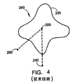
実際の設定、例えば都会的環境では、マルチパスおよび他の考慮事項により放射パターンが不均一になる。信号は、従来のワイヤレス通信デバイスの単一のアンテナ200に到達する前に、例えば地面、建物、壁または他の反射構造物で反射し得る。さらに、信号が単一のアンテナに到達する前に空間および時間における複数のパスに同時に散乱し得るため、信号は建設的および破壊的にそれ自体と干渉し得る。図4は、単一のアンテナ200から生成されるゲインライン230を含むマルチパス放射パターン260の一例を示す、別の極性プロットを表す。ゲインライン230はマルチパス干渉によって歪みを生じている。そのため、例えば点240、250は単一のアンテナから等距離にあるが、実際には点240、250からは異なる放射パターンが見られる。点240からは点250からよりも、大きな信号ゲインが見える。
【0004】
したがって、従来のワイヤレス通信デバイスは、マルチパス状態のために受信および送信が不良であるという問題点を有し、従来のワイヤレス通信デバイスのユーザは典型的には、より向上した信号をランダムにサーチしようとして物理的に動き回る必要がある(例えば放射パターン260の形状を知ることなく点250から点240に動く必要がある)。従来のワイヤレス通信デバイスをこのように物理的に平行移動させることは不便であり、例えばユーザが自由に動き回ることができないなどの条件下においては使用不可能であり得る。
【0005】
さらに、マルチパスの影響は部分的に、信号の建設的および破壊的干渉から起こるため、信号の周波数が異なればマルチパスの影響も異なる。したがって例えば図5の極性プロットに示すように、第1のゲインライン270が第1の周波数f1で単一のアンテナ200によって生成され、第2のゲインライン280が第2の周波数f2で単一のアンテナ200によって生成される。
【0006】
従来のワイヤレス通信デバイスは異なる周波数で信号を送受信し得る。したがって従来のワイヤレス通信デバイスは、例えば信号単一のアンテナを介して、第1の周波数f1で送信し第2の周波数f2で受信することがあり得る。従来のワイヤレス通信デバイスは、例えばゲインライン270で表される送信用放射パターンとゲインライン280で表される受信用放射パターンとを実際に経験する。例えば単一のアンテナ200と点290(例えばベース局)との間の2方向ワイヤレス通信中の結果をさらに図5に示す。点290およびアンテナ200は、単一のアンテナ200が送信中であるか受信中であるかに依存して異なる放射パターンを実際に経験する。この場合、単一のアンテナ200は、点290に信号を送信する際よりも点290から信号を受信する際に、実質的により多くのゲインを実際に経験する。したがって、例えば、点290からの信号はうまく受信されても点290に送信された信号が失われるということがあり得る。
【発明の開示】
【課題を解決するための手段】
【0007】
本発明は、ワイヤレス通信システムにおいて情報を受信および送信する従来の装置および方法の不利な点を大幅に緩和する。
【0008】
好適な実施形態において、本発明は、マルチパス環境で情報を受信および送信するシステムおよび方法を提供する。本発明は、第1のアンテナ、第2のアンテナ、スイッチングモジュール、受信器モジュール、および送信器モジュールを含む。スイッチングモジュールは、第1のアンテナおよび第2のアンテナの受信特性に応じて、第1のアンテナおよび第2のアンテナの一方に受信器モジュールを接続するように適合されている。スイッチングモジュールはさらに、第1のアンテナおよび第2のアンテナの送信特性に応じて、第1のアンテナおよび第2のアンテナの一方に送信器モジュールを接続するように適合されている。
【0009】
本発明は、ワイヤレス通信デバイスが第1のアンテナおよび第2のアンテナを提供するという利点を有する。ワイヤレス通信デバイスは、送信特性または受信特性を最適化するために第1のアンテナまたは第2のアンテナのいずれかを選択し得る。本発明は、ワイヤレス通信デバイスが自動的に送信器モジュールを、最良の送信特性を有するアンテナに接続し得るという利点を有する。本発明はさらに、ワイヤレス通信デバイスが自動的に受信器モジュールを、最良の受信特性を有するアンテナに接続し得るという利点を有する。
【0010】
本発明のこれらおよび他の利点は、本発明の以下の詳細な説明を添付の図面と共に検討することにより明らかになる。以下の説明および添付の図面を通して、同様の部品には同様の参照符号を付す。
【発明を実施するための最良の形態】
【0011】
図1は、本発明によるワイヤレス通信デバイス100を含むワイヤレス通信システムの実施形態を示す。ワイヤレス通信デバイス100は、例えば、ハンドヘルドワイヤレス通信デバイス、モバイル電話、自動車電話、携帯またはパーソナル通信サービス(PCS)電話、コードレス電話、ラップトップコンピュータまたはワイヤレスモデムを有する他のコンピューティングデバイス、ページャまたはパーソナルデジタルアシスタント(PDA)を含み得る。ワイヤレスデバイス100はデジタルでもよいし、アナログでもよいし、それらを何らかの形で組み合わせたものでもよい。実際、本発明は、当業者に公知の他の形態のワイヤレス通信デバイスをも考慮している。
【0012】
ワイヤレス通信デバイス100は、例えば、第1のアンテナ110と、第2のアンテナ120と、スイッチングモジュール130と、送信器モジュール140と、受信器モジュール150と、メインコントローラ160とを含み得る。スイッチングモジュール130は、例えば、受信器スイッチ170と送信器スイッチ180とを含み得る。メインコントローラ160は、例えば、モバイル局モデム(MSM)またはプログラマブルな他のプロセッサを含み得る。ワイヤレス通信デバイス100はさらに、当業者に公知であり本明細書にこれ以上示しも記載もしていない他のコンポーネント(例えば、デュプレクサ、ディプレクサ、増幅器、ミキサ、フィルタ、発振器など)をも含み得る。
【0013】
図2Aおよび図2Bを参照すると、ワイヤレス通信デバイス100は可能性のある1つの配置で示されている。本実施例において、ワイヤレス通信デバイス100は2つのアンテナ、すなわち第1の方位にある第1のアンテナ110および第2の方位にある第2のアンテナ120を含む。好適には、第1のアンテナ110は、第1のアンテナ110および第2のアンテナ120からの異なるゲインパターンを強調する直交関係または他の関係で位置づけられる。さらに本実施例において、第1のアンテナ110は、アンテナが少なくとも部分的にワイヤレス通信デバイス100のハウジング外に延びるように搭載され、第2のアンテナ120はハウジング内に搭載されている。特定の応用および美的考慮をサポートするために、アンテナを搭載する他の方位または位置も選択され得ることが理解される。
【0014】
図示する実施例では、ワイヤレス通信デバイス100は図2Aに示すように、周波数f1で送信し、図2Bに示すように周波数f2で受信する。上述したように、各アンテナ110、120が、周波数f1において、周波数f2でのゲインラインと異なるゲインラインを有することがあり得る。例えば、第1のアンテナ110は、図2Aに示すように周波数f1で動作する際にゲインライン115を有する放射パターンを有し、図2Bに示すように周波数f2で動作する際にゲインライン116を有する放射パターンを有する。同様に、第2のアンテナ120は、図2Aに示すように周波数f1で動作する際にゲインライン125を有する放射パターンを有し、図2Bに示すように周波数f2で動作する際にゲインライン126を有する放射パターンを有する。
【0015】
ワイヤレス通信デバイス100は、例えばゲインライン115とゲインライン125との間、またはゲインライン116とゲインライン126との間、などのゲインライン差を有利に用いて、ワイヤレス通信デバイス100の動作を向上させる。例えば、ワイヤレス通信デバイス100は、第1のアンテナ110と第2のアンテナ120とのいずれが通信信号を送受信するために良好であるかを決定し得、現在の通信にとってより良好なアンテナを選択し得る。このようにして、より一貫性のある信号の質が得られ得、これにより例えば、呼の喪失が減少し得、より低パワーでの使用が可能にあり得、あるいはより高速のデータ送信が可能になり得る。ゲインラインは、ワイヤレス通信デバイス100の移動または環境の変化に対する応答において変化し得るため、ワイヤレス通信デバイス100は常により良好なアンテナを決定および選択し得る。したがって、ワイヤレス通信デバイス100は、移動中またはアクティブかつダイナミックな環境で動作しているときにも、より一貫した信号の質を維持し得る。
【0016】
図1を参照して、ワイヤレス通信デバイス100をより詳細に説明する。メインコントローラ160は、送信器モジュール140と受信器モジュール150とスイッチングモジュール130とに接続されている。送信器モジュール140はスイッチングモジュール130の送信器スイッチ180に接続されている。送信器スイッチ180を介して、送信器モジュール140が第1のアンテナ110および第2のアンテナ120の一方に接続され得る。受信器モジュール150はスイッチングモジュール130の受信器スイッチ170に接続されている。受信器スイッチ170を介して、受信器モジュール160が第1のアンテナ110および第2のアンテナ120の一方に接続され得る。
【0017】
第1のアンテナ110および第2のアンテナ120は概して同一の方向に示されているが、これらは互いに角度を有して配置され得る。例えば、第1のアンテナ110は好適には第2のアンテナ120に対してほぼ直交する方向に配置される。アンテナの方位はその放射パターンに影響を与えるため、第1のアンテナ110および第2のアンテナ120は異なる放射パターンを有し得る。したがって第2のアンテナ120は、ワイヤレス通信デバイス100の他の放射パターンを提供し得る。
【0018】
一実施形態による動作では、メインコントローラ160は、第1のアンテナ110または第2のアンテナ120を介してワイヤレス通信ネットワークのベース局から信号を受け取る。この信号に基づいて、メインコントローラ160が、例えば周波数f1で送信すべき送信器モジュール140と周波数f2で受信すべき受信器モジュール150を設定する。メイン160は、アンテナ110および120のうちいずれが現在の環境において周波数f2で最良の受信特性を提供するかを評価し得る。現在の環境はマルチパスを含み得る。メインコントローラ160はさらに、アンテナ110および120のうちいずれが現在の環境において周波数f1で最良の送信特性(例えば、信号強度、明瞭度、ビットエラーレートなど)を提供するかを評価し得る。評価は定期的または不定期に(例えば、特定の条件によりトリガされる際に)起こり得る。これらの評価に基づき、メインコントローラ160は、送信器モジュール140または受信器モジュール150を適切なアンテナ110または120に切り換えるようにスイッチングモジュール130を制御する。
【0019】
例えば、ワイヤレス通信デバイス100とワイヤレス通信ネットワーク内のベース局との間の2方向通信中(例えば、接続された呼者間の会話中)、メインコントローラ160は、例えば周波数f2における割り当てられたチャネルには、第1のアンテナ110が現在の環境において第2のアンテナ120よりも良好な受信を提供すると決定し得る。したがって、メインコントローラ160は、第1のスイッチ170が受信器モジュール150を第1のアンテナ110に接続するような制御信号をスイッチングモジュール130に送る。メインコントローラ160はさらに例えば、周波数f1における割り当てられたチャネルには、第1のアンテナ110が現在の環境においてより良好な送信を提供すると決定し得る。したがって、メインコントローラ160は、第2のスイッチ180が送信器モジュール140を第1のアンテナ110に接続するような制御信号をスイッチングモジュール130に送る。
【0020】
別の実施形態による動作では、受信器モジュール150がスイッチングモジュール130の第1のスイッチ170を介して例えば第1のアンテナ110に接続される。メインコントローラ160は第1のアンテナ110の受信特性を監視する。受信特性が悪化すると(例えば、ビットエラーレートが、適用可能なエラー閾値を越えるか、または閾値に近づくと)、メインコントローラ160は第2のアンテナ110の受信特性をテストする。例えば、メインコントローラ160は、第2のアンテナ120の受信特性をテストするために、第1のスイッチ170が受信器モジュール150を第2のアンテナ120に接続するようにスイッチングモジュール130を制御する。これは、相対的に迅速に行われ得る。例えば、第2のアンテナ120の受信特性が、例えば、第2のアンテナ120のエラービットレートに基づいて評価された場合、評価はビット毎でも決定され得る。
【0021】
メインコントローラ160が、第2のアンテナ120がより良好な受信特性(例えばより低いビットエラーレート)を有していると決定した場合、メインコントローラ160は、受信器モジュール150を第2のアンテナ120に接続したままにし得る。メインコントローラ160はその後第2のアンテナ120の受信特性を監視する。他方、メインコントローラ160が、第2のアンテナ120はより良好な受信特性を有していないと決定した場合、メインコントローラ160はスイッチングモジュールを制御して、第1のスイッチが受信器モジュール150と第1のアンテナ110との間の接続を維持するようにする。
【0022】
アンテナ110、120の送信特性を監視する際にも同様の手順がメインコントローラ160によって行われ得る。例えば、メインコントローラ160は、ベース局からのフィードバックを介して送信特性(例えば、信号強度)を監視し得る。したがって、送信に使用中のアンテナ、例えば、第2のアンテナ120の送信特性が悪化すると(例えば、信号強度が特定の強度閾値を越えるか、または閾値に近づくと)、メインコントローラ160は他のアンテナ、例えば第1のアンテナの送信特性をテストし得る。これは、送信器モジュール140を第1のアンテナ110に接続することによって行われる。アンテナ110、120の送信特性を評価する際に、メインコントローラ160はベース局からのフィードバック情報(例えば、クローズドループパワーコントロール)を用い得る。この実施例において第1のアンテナ110がより良好な送信特性を有している場合、メインコントローラ160は送信器モジュール140と第1のアンテナ110との間の接続を維持する。メインコントローラ160はその後、第1のアンテナ110の送信特性を監視する。他方、メインコントローラ160が第1のアンテナ110はより良好な送信特性を有していないと決定した場合、メインコントローラ160はスイッチングモジュールを制御して、第2のスイッチ180が送信器モジュール140を第2のアンテナ120に接続するようにする。
【0023】
別の実施形態においては、メインコントローラ160が、例えば送信特性を向上させるために例えばアンテナを第1のアンテナ110から第2のアンテナに切り換えた後、メインコントローラ160は受信特性を新しい送信特性に合致させることを試み得る。この実施例において、第2のアンテナ120が特定の質の強度パラメータを含む送信特性を有している場合、メインコントローラ160は第1のアンテナ110および第2のアンテナ120の受信特性をテストして、いずれのアンテナが特定の質により近い受信特性、特に本実施例においては強度パラメータを有しているかを評価する。選択されたアンテナ110または120は、必ずしも例えば最大の強度パラメータを有しているわけではなく、最も近い合致強度パラメータを有している。
【0024】
さらなる実施形態において、メインコントローラ160は、第1のアンテナ110および第2のアンテナ120の少なくとも一方の範囲内にあるベース局のリストを維持する。このリストは、ワイヤレス通信デバイス100が、例えば登録プロセスまたは他の初期プロセス中にワイヤレス通信デバイス100の範囲内にあるすべてのベース局から信号を受け取る際に、収集され得る。さらに、リストは、定期的に又は不定期に(例えば、特定の条件またはイベントによってトリガされる際に)、更新され得る。したがって、現在送信に用いられているアンテナの送信特性が悪化すると、メインコントローラ160は、リスト上のベース局の各々で、各々のアンテナの送信特性をテストし得る。このようなテストに基づいて、アンテナまたはベース局の切り換えが行われ得る。現在受信に用いられているアンテナの受信特性が悪化すると、メインコントローラ160は、リスト上のベース局の各々で、各々のアンテナの受信特性をテストし得る。このようなテストに基づいて、アンテナまたはベース局の切り換えが行われ得る。
【0025】
このように、マルチパス環境において情報を受信および送信するシステムおよび方法が提供されることが理解される。当業者は、本発明は本明細書に限定の目的ではなく説明の目的で記載された好適な実施形態以外の実施形態でも実施され得ること、および本発明は特許請求の範囲によってのみ限定されることを理解する。本明細書に記載の特定の実施形態の均等物もまた本発明を実施し得ることに留意されたい。
【図面の簡単な説明】
【0026】
【図1】図1は、本発明によるワイヤレス通信デバイスのいくつかのコンポーネントを模式的に表す図である。
【図2A】図2Aは、本発明によるワイヤレスデバイスを示す図である。
【図2B】図2Bは、本発明によるワイヤレスデバイスを示す図である。
【図3】図3は、従来のアンテナの等方性放射パターンの極性プロットを示す。
【図4】図4は、従来のアンテナのマルチパス環境における放射パターンの極性プロットを示す。
【図5】図5は、従来のアンテナのマルチパス環境における、異なる周波数での放射パターンの極性プロットを示す。【Technical field】
[0001]
The present invention relates generally to systems and methods for receiving and transmitting information using wireless networks, and more particularly to antenna systems and methods for receiving and transmitting information in a wireless multipath environment.
[Background Art]
[0002]
Signals received and transmitted by conventional wireless communication devices in a wireless communication network are affected by the surrounding environment. Theoretically, a conventional wireless communication device having a
[0003]
In a practical setting, eg, an urban environment, multipath and other considerations will result in non-uniform radiation patterns. Before reaching the
[0004]
Therefore, conventional wireless communication devices have the problem of poor reception and transmission due to multipath conditions, and users of conventional wireless communication devices typically randomly search for improved signals. They need to physically move around (eg, need to move from
[0005]
In addition, multipath effects are different due to the constructive and destructive interference of the signal, so different signal frequencies have different multipath effects. Thus, for example, as shown in the polarity plot of Figure 5, the
[0006]
Conventional wireless communication devices may send and receive signals at different frequencies. Thus the conventional wireless communications device, for example via a signal single antenna may be received by the transmission and a second frequency f 2 in the first frequency f 1. Conventional wireless communication devices actually experience, for example, a transmit radiation pattern represented by
DISCLOSURE OF THE INVENTION
[Means for Solving the Problems]
[0007]
The present invention significantly alleviates the disadvantages of conventional devices and methods for receiving and transmitting information in a wireless communication system.
[0008]
In a preferred embodiment, the present invention provides a system and method for receiving and transmitting information in a multipath environment. The present invention includes a first antenna, a second antenna, a switching module, a receiver module, and a transmitter module. The switching module is adapted to connect the receiver module to one of the first antenna and the second antenna according to a receiving characteristic of the first antenna and the second antenna. The switching module is further adapted to connect the transmitter module to one of the first antenna and the second antenna depending on a transmission characteristic of the first antenna and the second antenna.
[0009]
The present invention has the advantage that a wireless communication device provides a first antenna and a second antenna. The wireless communication device may select either the first antenna or the second antenna to optimize transmission characteristics or reception characteristics. The invention has the advantage that the wireless communication device can automatically connect the transmitter module to the antenna with the best transmission characteristics. The invention has the further advantage that the wireless communication device can automatically connect the receiver module to the antenna with the best reception characteristics.
[0010]
These and other advantages of the present invention will become apparent from the following detailed description of the invention when considered in conjunction with the accompanying drawings. Throughout the following description and the accompanying drawings, like parts are designated by like reference numerals.
BEST MODE FOR CARRYING OUT THE INVENTION
[0011]
FIG. 1 shows an embodiment of a wireless communication system including a wireless communication device 100 according to the present invention. The wireless communication device 100 may be, for example, a handheld wireless communication device, a mobile phone, a car phone, a mobile or personal communication service (PCS) phone, a cordless phone, a laptop computer or other computing device with a wireless modem, a pager or personal digital device. An assistant (PDA) may be included. Wireless device 100 may be digital, analog, or some combination thereof. Indeed, the present invention contemplates other forms of wireless communication devices known to those skilled in the art.
[0012]
The wireless communication device 100 may include, for example, a first antenna 110, a second antenna 120, a switching module 130, a transmitter module 140, a receiver module 150, and a main controller 160. Switching module 130 may include, for example, a receiver switch 170 and a transmitter switch 180. Main controller 160 may include, for example, a mobile station modem (MSM) or other programmable processor. Wireless communication device 100 may also include other components (eg, duplexers, duplexers, amplifiers, mixers, filters, oscillators, etc.) known to those of skill in the art and not further shown or described herein.
[0013]
Referring to FIGS. 2A and 2B, the wireless communication device 100 is shown in one possible arrangement. In this embodiment, wireless communication device 100 includes two antennas, a first antenna 110 in a first orientation and a second antenna 120 in a second orientation. Preferably, first antenna 110 is positioned in an orthogonal or other relationship that emphasizes different gain patterns from first antenna 110 and second antenna 120. Further, in this embodiment, the first antenna 110 is mounted such that the antenna extends at least partially outside the housing of the wireless communication device 100, and the second antenna 120 is mounted within the housing. It is understood that other orientations or positions for mounting the antenna may be selected to support particular applications and aesthetic considerations.
[0014]
In the illustrated embodiment, wireless communication device 100, as shown in FIG. 2A, transmits at frequency f 1, to receive at the frequency f 2 as shown in Figure 2B. As described above, each antenna 110 and 120 at the frequency f 1, may have a gain line with different gains line at the frequency f 2. For example, the first antenna 110 has a radiation pattern having a gain line 115 when operating at a frequency f 1 as shown in FIG. 2A, and a gain line when operating at a frequency f 2 as shown in FIG. 2B. It has a radiation pattern having 116. Similarly, the second antenna 120 has a radiation pattern with a gain line 125 when operating at frequency f 1 as shown in FIG. 2A and gain when operating at frequency f 2 as shown in FIG. 2B. It has a radiation pattern with lines 126.
[0015]
Wireless communication device 100 advantageously utilizes gain line differences, such as between gain line 115 and gain line 125, or between gain line 116 and gain line 126, to enhance operation of wireless communication device 100. . For example, the wireless communication device 100 may determine which of the first antenna 110 and the second antenna 120 is better for transmitting and receiving communication signals and select a better antenna for current communication. obtain. In this way, a more consistent signal quality may be obtained, for example, which may reduce call loss, may allow for lower power use, or allow for faster data transmission Can be Since the gain line may change in response to movement or environmental changes of the wireless communication device 100, the wireless communication device 100 may always determine and select a better antenna. Accordingly, wireless communication device 100 may maintain more consistent signal quality when moving or operating in an active and dynamic environment.
[0016]
With reference to FIG. 1, the wireless communication device 100 will be described in more detail. The main controller 160 is connected to the transmitter module 140, the receiver module 150, and the switching module 130. The transmitter module 140 is connected to the transmitter switch 180 of the switching module 130. Via a transmitter switch 180, a transmitter module 140 may be connected to one of the first antenna 110 and the second antenna 120. The receiver module 150 is connected to the receiver switch 170 of the switching module 130. Via a receiver switch 170, a receiver module 160 may be connected to one of the first antenna 110 and the second antenna 120.
[0017]
Although the first antenna 110 and the second antenna 120 are shown generally in the same direction, they may be positioned at an angle to one another. For example, the first antenna 110 is preferably arranged in a direction substantially orthogonal to the second antenna 120. First antenna 110 and second antenna 120 may have different radiation patterns because the orientation of the antenna affects its radiation pattern. Thus, second antenna 120 may provide another radiation pattern for wireless communication device 100.
[0018]
In operation according to one embodiment, main controller 160 receives a signal from a base station of a wireless communication network via first antenna 110 or second antenna 120. Based on this signal, the main controller 160, for example, to set the receiver module 150 to be received by the transmitter module 140 and the frequency f 2 to be transmitted at the frequency f 1. The main 160, one of the antennas 110 and 120 may evaluate whether to provide the best reception characteristics at the frequency f 2 in the current environment. Current environments may include multipath. Main controller 160 may further evaluate which of antennas 110 and 120 provides the best transmission characteristics (eg, signal strength, clarity, bit error rate, etc.) at frequency f 1 in the current environment. Evaluations can occur periodically or irregularly (eg, when triggered by certain conditions). Based on these evaluations, the main controller 160 controls the switching module 130 to switch the transmitter module 140 or the receiver module 150 to the appropriate antenna 110 or 120.
[0019]
For example, during two-way communication between the wireless communication device 100 and a base station in the wireless communication network (eg, during a conversation between connected callers), the main controller 160 may, for example, assign an assigned channel at frequency f 2 May determine that the first antenna 110 provides better reception than the second antenna 120 in the current environment. Accordingly, the main controller 160 sends a control signal to the switching module 130 such that the first switch 170 connects the receiver module 150 to the first antenna 110. Main controller 160 may further determine, for example, that for the assigned channel at frequency f 1 , first antenna 110 provides better transmission in the current environment. Accordingly, the main controller 160 sends a control signal to the switching module 130 such that the second switch 180 connects the transmitter module 140 to the first antenna 110.
[0020]
In operation according to another embodiment, the receiver module 150 is connected to the first antenna 110 via the first switch 170 of the switching module 130, for example. The main controller 160 monitors the reception characteristics of the first antenna 110. If the reception characteristics deteriorate (eg, if the bit error rate exceeds or approaches an applicable error threshold), the main controller 160 tests the reception characteristics of the second antenna 110. For example, the main controller 160 controls the switching module 130 so that the first switch 170 connects the receiver module 150 to the second antenna 120 to test the reception characteristics of the second antenna 120. This can be done relatively quickly. For example, when the reception characteristics of the second antenna 120 are evaluated based on, for example, the error bit rate of the second antenna 120, the evaluation may be determined for each bit.
[0021]
If the main controller 160 determines that the second antenna 120 has better reception characteristics (eg, a lower bit error rate), the main controller 160 may switch the receiver module 150 to the second antenna 120. May stay connected. The main controller 160 then monitors the reception characteristics of the second antenna 120. On the other hand, if the main controller 160 determines that the second antenna 120 does not have better reception characteristics, the main controller 160 controls the switching module so that the first switch is The connection with one antenna 110 is maintained.
[0022]
A similar procedure can be performed by the main controller 160 when monitoring the transmission characteristics of the antennas 110 and 120. For example, main controller 160 may monitor transmission characteristics (eg, signal strength) via feedback from a base station. Thus, if the transmission characteristics of the antenna being used for transmission, eg, the second antenna 120, deteriorate (eg, if the signal strength exceeds or approaches a certain strength threshold), the main controller 160 may switch to another antenna. For example, the transmission characteristics of the first antenna may be tested. This is done by connecting the transmitter module 140 to the first antenna 110. In evaluating the transmission characteristics of antennas 110, 120, main controller 160 may use feedback information from a base station (eg, closed loop power control). If the first antenna 110 has better transmission characteristics in this embodiment, the main controller 160 maintains the connection between the transmitter module 140 and the first antenna 110. The main controller 160 then monitors the transmission characteristics of the first antenna 110. On the other hand, if the main controller 160 determines that the first antenna 110 does not have better transmission characteristics, the main controller 160 controls the switching module so that the second switch 180 2 antenna 120.
[0023]
In another embodiment, after the main controller 160 switches the antenna from the first antenna 110 to the second antenna, for example, to improve the transmission characteristics, the main controller 160 matches the reception characteristics to the new transmission characteristics, for example. You can try to make it happen. In this embodiment, if the second antenna 120 has a transmission characteristic including a specific quality intensity parameter, the main controller 160 tests the reception characteristics of the first antenna 110 and the second antenna 120. Evaluate which antenna has a receiving characteristic closer to a specific quality, in particular, in this embodiment, has an intensity parameter. The selected antenna 110 or 120 does not necessarily have, for example, the largest intensity parameter, but has the closest matching intensity parameter.
[0024]
In a further embodiment, main controller 160 maintains a list of base stations that are within range of at least one of first antenna 110 and second antenna 120. This list may be gathered when wireless communication device 100 receives signals from all base stations within range of wireless communication device 100, for example, during a registration process or other initial process. Further, the list may be updated periodically or irregularly (eg, when triggered by certain conditions or events). Therefore, if the transmission characteristics of the antenna currently being used for transmission deteriorate, the main controller 160 may test the transmission characteristics of each antenna at each of the base stations on the list. Based on such a test, an antenna or base station switch may be performed. If the reception characteristics of the antenna currently used for reception deteriorate, the main controller 160 may test the reception characteristics of each antenna at each of the base stations on the list. Based on such a test, an antenna or base station switch may be performed.
[0025]
Thus, it is understood that systems and methods for receiving and transmitting information in a multipath environment are provided. Those skilled in the art will appreciate that the present invention may be practiced with embodiments other than the preferred embodiments described for purposes of explanation and not limitation, and that the invention is limited only by the following claims. Understand that. Note that equivalents of the particular embodiments described herein may also practice the invention.
[Brief description of the drawings]
[0026]
FIG. 1 is a diagram that schematically represents some components of a wireless communication device according to the present invention.
FIG. 2A illustrates a wireless device according to the present invention.
FIG. 2B illustrates a wireless device according to the present invention.
FIG. 3 shows a polarity plot of the isotropic radiation pattern of a conventional antenna.
FIG. 4 shows a polarity plot of the radiation pattern in a multipath environment of a conventional antenna.
FIG. 5 shows a polarity plot of the radiation pattern at different frequencies in a multipath environment of a conventional antenna.
Claims (27)
第2のアンテナと、
該第1のアンテナと該第2のアンテナとに接続されたスイッチングモジュールと、
該スイッチングモジュールを介して該第1のアンテナと該第2のアンテナとに接続された受信器モジュールと、
該スイッチングモジュールを介して該第1のアンテナと該第2のアンテナとに接続された送信器モジュールと、
を備えたワイヤレス通信デバイスであって、
該スイッチングモジュールが、該第1のアンテナおよび該第2のアンテナの受信特性に応じて該第1のアンテナおよび該第2のアンテナの一方に該受信器モジュールを接続するように適合され、
該スイッチングモジュールが、該第1のアンテナおよび該第2のアンテナの送信特性に応じて該第1のアンテナおよび該第2のアンテナの一方に該送信器モジュールを接続するように適合されている、ワイヤレス通信デバイス。A first antenna;
A second antenna;
A switching module connected to the first antenna and the second antenna;
A receiver module connected to the first antenna and the second antenna via the switching module;
A transmitter module connected to the first antenna and the second antenna via the switching module;
A wireless communication device comprising:
The switching module is adapted to connect the receiver module to one of the first antenna and the second antenna according to a reception characteristic of the first antenna and the second antenna;
The switching module is adapted to connect the transmitter module to one of the first antenna and the second antenna according to transmission characteristics of the first antenna and the second antenna; Wireless communication device.
前記送信器モジュールが、該第1のスイッチを介して前記第1のアンテナと前記第2のアンテナとに接続され、
前記送信器モジュールが、該第2のスイッチを介して該第1のアンテナと該第2のアンテナとに接続されている、請求項1に記載のワイヤレス通信デバイス。The switching module includes a first switch and a second switch;
The transmitter module is connected to the first antenna and the second antenna via the first switch;
The wireless communication device according to claim 1, wherein the transmitter module is connected to the first antenna and the second antenna via the second switch.
第2のアンテナと、
該第1のアンテナおよび該第2のアンテナの送信特性に応じて、該第1のアンテナおよび該第2のアンテナの一方を、情報の送信に用いるために選択する第1の手段と、
該第1のアンテナおよび該第2のアンテナの受信特性に応じて、該第1のアンテナおよび該第2のアンテナの一方を、情報の受信に用いるために選択する第2の手段と、
を備えた、ワイヤレス通信デバイス内のダイバーシチアンテナを提供するシステム。A first antenna;
A second antenna;
First means for selecting one of the first antenna and the second antenna for use in transmitting information according to transmission characteristics of the first antenna and the second antenna;
A second means for selecting one of the first antenna and the second antenna for use in receiving information according to reception characteristics of the first antenna and the second antenna;
A system for providing a diversity antenna in a wireless communication device, comprising:
該第1のアンテナおよび該第2のアンテナのうち、前記第2の手段によって選択された一方に受信器モジュールを接続する手段と、
をさらに備えた、請求項13に記載のシステム。Means for connecting a transmitter module to one of the first antenna and the second antenna selected by the first means;
Means for connecting a receiver module to one of the first antenna and the second antenna selected by the second means;
14. The system of claim 13, further comprising:
(a)該特定のマルチパス環境における第1のアンテナおよび第2のアンテナの送信特性に応じて、該第1のアンテナおよび該第2のアンテナの一方を情報の送信に用いるために選択する工程と、
(b)該特定のマルチパス環境における該第1のアンテナおよび該第2のアンテナの受信特性に応じて、該第1のアンテナおよび該第2のアンテナの一方を情報の受信に用いるために選択する工程と、
(c)該第1のアンテナおよび該第2のアンテナのうち工程(a)で選択された一方に該送信すべき情報を接続する工程と、
(d)該第1のアンテナおよび該第2のアンテナのうち工程(b)で選択された一方に該受信すべき情報を接続する工程と、
を包含する方法。A method for receiving and transmitting information in a specific multipath environment, comprising:
(A) selecting one of the first antenna and the second antenna for use in transmitting information according to transmission characteristics of the first antenna and the second antenna in the specific multipath environment; When,
(B) selecting one of the first antenna and the second antenna for use in receiving information according to reception characteristics of the first antenna and the second antenna in the specific multipath environment; The process of
(C) connecting the information to be transmitted to one of the first antenna and the second antenna selected in step (a);
(D) connecting the information to be received to one of the first antenna and the second antenna selected in step (b);
A method that includes:
(b)該受信器モジュールに接続された、該ワイヤレス通信デバイスの第2のアンテナの受信特性を評価する工程と、
(c)該第1のアンテナに代えて該第2のアンテナに該受信器モジュールを接続する工程と、
を包含する、ワイヤレス通信方法。(A) monitoring a reception characteristic of a first antenna of the wireless communication device connected to a receiver module of the wireless communication device;
(B) evaluating the receiving characteristics of a second antenna of the wireless communication device connected to the receiver module;
(C) connecting the receiver module to the second antenna instead of the first antenna;
A wireless communication method.
(e)該第1のアンテナおよび該第2のアンテナのうち、該第2のアンテナの前記受信特性により密接に合致する送信特性を有する一方に、前記ワイヤレス通信デバイスの送信器モジュールを接続する工程と、
をさらに包含する、請求項16に記載の方法。(D) evaluating transmission characteristics of the first antenna and the second antenna;
(E) connecting a transmitter module of the wireless communication device to one of the first antenna and the second antenna having a transmission characteristic that more closely matches the reception characteristic of the second antenna. When,
17. The method of claim 16, further comprising:
(b)該送信器モジュールに接続された、該ワイヤレス通信デバイスの第2のアンテナの送信特性を評価する工程と、
(c)該第1のアンテナに代えて該第2のアンテナに該送信器モジュールを接続する工程と、
を包含する、ワイヤレス通信方法。(A) monitoring a transmission characteristic of a first antenna of the wireless communication device connected to a transmitter module of the wireless communication device;
(B) evaluating a transmission characteristic of a second antenna of the wireless communication device connected to the transmitter module;
(C) connecting the transmitter module to the second antenna instead of the first antenna;
A wireless communication method.
(b)該ワイヤレス通信デバイスの受信器モジュールに接続された該第1のアンテナの受信特性を監視する工程と、
(c)該監視された受信特性が悪化した場合、該リスト上の該第1のアンテナと該ベース局との間、および該リスト上の該第2のアンテナと該ベース局との間の受信特性をテストする工程と、
(d)特定のアンテナおよび特定のベース局の該テストされた受信特性が該監視された受信特性よりも良好である場合、該受信器モジュールを該特定のアンテナに接続し、該ワイヤレス通信デバイスをワイヤレスで該特定のベース局に接続する工程と、
を包含するワイヤレス通信方法。(A) generating a list of base stations within range of the wireless communication device for a first antenna and a second antenna of the wireless communication device;
(B) monitoring a reception characteristic of the first antenna connected to a receiver module of the wireless communication device;
(C) reception between the first antenna on the list and the base station and between the second antenna on the list and the base station if the monitored reception characteristic deteriorates. Testing the properties;
(D) if the tested reception characteristics of a particular antenna and a particular base station are better than the monitored reception characteristics, connect the receiver module to the particular antenna and connect the wireless communication device Wirelessly connecting to the particular base station;
A wireless communication method including:
(b)該ワイヤレス通信デバイスの送信器モジュールに接続された該第1のアンテナの送信特性を監視する工程と、
(c)該監視された送信特性が悪化した場合、該リスト上の該第1のアンテナと該ベース局の少なくとも1つとの間、および該リスト上の該第2のアンテナと該ベース局の少なくとも1つとの間の送信特性をテストする工程と、
(d)特定のアンテナおよび特定のベース局の該テストされた受信特性が該監視された送信特性よりも良好である場合、該送信器モジュールを該特定のアンテナに接続し、該ワイヤレス通信デバイスをワイヤレスで該特定のベース局に接続する工程と、
を包含するワイヤレス通信方法。(A) generating a list of base stations within range of the wireless communication device for a first antenna and a second antenna of the wireless communication device;
(B) monitoring transmission characteristics of the first antenna connected to a transmitter module of the wireless communication device;
(C) if the monitored transmission characteristic deteriorates, between the first antenna on the list and at least one of the base stations, and at least the second antenna on the list and the base station; Testing the transmission characteristics between one;
(D) if the tested reception characteristics of a particular antenna and a particular base station are better than the monitored transmission characteristics, connect the transmitter module to the particular antenna and connect the wireless communication device to the particular antenna; Wirelessly connecting to the particular base station;
A wireless communication method including:
Applications Claiming Priority (2)
| Application Number | Priority Date | Filing Date | Title |
|---|---|---|---|
| US09/902,035 US7103382B2 (en) | 2001-07-10 | 2001-07-10 | System and method for receiving and transmitting information in a multipath environment |
| PCT/IB2002/002721 WO2003007502A1 (en) | 2001-07-10 | 2002-07-10 | System and method for receiving and transmitting information in a multipath environment with diversity |
Publications (2)
| Publication Number | Publication Date |
|---|---|
| JP2004537207A true JP2004537207A (en) | 2004-12-09 |
| JP2004537207A5 JP2004537207A5 (en) | 2006-01-05 |
Family
ID=25415220
Family Applications (1)
| Application Number | Title | Priority Date | Filing Date |
|---|---|---|---|
| JP2003513147A Pending JP2004537207A (en) | 2001-07-10 | 2002-07-10 | System and method for receiving and transmitting information in a multipath environment using diversity |
Country Status (8)
| Country | Link |
|---|---|
| US (3) | US7103382B2 (en) |
| EP (1) | EP1405439B1 (en) |
| JP (1) | JP2004537207A (en) |
| CN (2) | CN101047413B (en) |
| AT (1) | ATE321381T1 (en) |
| DE (1) | DE60210083T2 (en) |
| ES (1) | ES2259711T3 (en) |
| WO (1) | WO2003007502A1 (en) |
Cited By (1)
| Publication number | Priority date | Publication date | Assignee | Title |
|---|---|---|---|---|
| JP2008538886A (en) * | 2005-04-28 | 2008-11-06 | エヌエックスピー ビー ヴィ | Wireless device |
Families Citing this family (32)
| Publication number | Priority date | Publication date | Assignee | Title |
|---|---|---|---|---|
| US7181171B2 (en) * | 2001-07-20 | 2007-02-20 | Kyocera Wireless Corp. | System and method for providing auxiliary reception in a wireless communications system |
| JP3744883B2 (en) * | 2002-06-05 | 2006-02-15 | 日本電気株式会社 | Mobile phone, analysis device built in the same, and analysis method thereof |
| JP4540936B2 (en) * | 2003-02-10 | 2010-09-08 | 富士通株式会社 | Mobile terminal |
| US6924766B2 (en) * | 2003-04-03 | 2005-08-02 | Kyocera Wireless Corp. | Wireless telephone antenna diversity system |
| EP1627446A1 (en) * | 2003-05-16 | 2006-02-22 | Philips Intellectual Property & Standards GmbH | Switchable multiband antenna for the high-frequency and microwave range |
| JP3915763B2 (en) * | 2003-09-19 | 2007-05-16 | 株式会社日立製作所 | Mobile device |
| KR100600707B1 (en) | 2004-07-23 | 2006-07-14 | 삼성전자주식회사 | Method for receiving wireless signal |
| US7627296B2 (en) | 2004-10-18 | 2009-12-01 | Research In Motion Limited | Method of controlling a plurality of internal antennas in a mobile communication device |
| US7176835B2 (en) * | 2005-01-28 | 2007-02-13 | Motorola, Inc. | Selecting an optimal antenna in a GPS receiver and methods thereof |
| US7890133B2 (en) * | 2005-02-09 | 2011-02-15 | Research In Motion Limited | Mobile wireless communications device providing pattern/frequency control features and related methods |
| US7729714B2 (en) * | 2005-12-20 | 2010-06-01 | Qualcomm Incorporated | Method and apparatus for reverse link transmit beam-forming |
| TWI275203B (en) * | 2005-12-30 | 2007-03-01 | Inventec Appliances Corp | Antenna system of GPS receiver and switching method of antenna |
| US7907094B2 (en) * | 2006-01-20 | 2011-03-15 | Panasonic Corporation | Portable terminal apparatus |
| TW200744332A (en) * | 2006-05-30 | 2007-12-01 | Benq Corp | Method and apparatus of receiving signals and wireless multimode wideband receiver |
| US8085786B2 (en) * | 2007-03-16 | 2011-12-27 | Qualcomm Incorporated | H-ARQ throughput optimization by prioritized decoding |
| JP5308439B2 (en) * | 2007-06-27 | 2013-10-09 | トムソン ライセンシング | Signal control apparatus and method |
| US20090191897A1 (en) * | 2008-01-24 | 2009-07-30 | Cortxt, Inc. | Environment Characterization for Mobile Devices |
| CN101778444B (en) * | 2009-01-12 | 2013-04-24 | 瑞昱半导体股份有限公司 | Device and method for choosing transmission path in wireless network |
| KR20100107801A (en) * | 2009-03-26 | 2010-10-06 | 삼성전자주식회사 | Apparatus and method for antenna selection in wireless communication system |
| CN104901735A (en) * | 2009-11-04 | 2015-09-09 | 日本电气株式会社 | Control method for wireless communication system, wireless communication system, and wireless communication device |
| JP5356185B2 (en) * | 2009-11-05 | 2013-12-04 | 前田金属工業株式会社 | Antenna switching method for wireless communication system |
| US8874041B2 (en) * | 2011-10-03 | 2014-10-28 | Apple Inc. | Electronic device with service acquisition antenna switching |
| US9344174B2 (en) | 2012-05-21 | 2016-05-17 | Qualcomm Incorporated | Systems, apparatus, and methods for antenna selection |
| US9819080B2 (en) | 2012-05-21 | 2017-11-14 | Qualcomm Incorporated | Methods and systems for antenna switching based on uplink metrics |
| CN104617993B (en) * | 2014-12-23 | 2019-02-05 | 武汉正维电子技术有限公司 | A kind of orthogonal double antenna micro power radio communication method and apparatus |
| US10615499B2 (en) * | 2015-01-14 | 2020-04-07 | Skywave Mobile Communications Inc. | Dual role antenna assembly |
| CN106539569A (en) * | 2015-12-10 | 2017-03-29 | 悦享趋势科技(北京)有限责任公司 | Wearable physiological monitoring equipment and its antenna system |
| US9947993B2 (en) * | 2016-08-12 | 2018-04-17 | Microsoft Technology Licensing, Llc | Antenna stack |
| CN106299700B (en) * | 2016-09-12 | 2018-04-20 | 广东欧珀移动通信有限公司 | Antenna structure and mobile terminal |
| CN108965560B (en) * | 2018-07-16 | 2020-04-24 | 厦门美图移动科技有限公司 | Antenna state detection method and terminal equipment |
| KR20200121176A (en) * | 2019-04-15 | 2020-10-23 | 삼성전자주식회사 | Positioning signal receiver and operating method thereof |
| US11635528B2 (en) | 2020-08-12 | 2023-04-25 | Rockwell Collins, Inc. | GPS receiver module |
Family Cites Families (46)
| Publication number | Priority date | Publication date | Assignee | Title |
|---|---|---|---|---|
| US3628149A (en) * | 1968-12-19 | 1971-12-14 | Bell Telephone Labor Inc | Diversity switch for digital transmission |
| IL67379A (en) * | 1982-12-01 | 1985-11-29 | Tadiran Israel Elect Ind Ltd | Real-time frequency management system for hf communication networks |
| US4513412A (en) * | 1983-04-25 | 1985-04-23 | At&T Bell Laboratories | Time division adaptive retransmission technique for portable radio telephones |
| JPH0778532B2 (en) | 1988-06-20 | 1995-08-23 | 日本無線株式会社 | Diversity reception GPS receiver |
| US5095535A (en) * | 1988-07-28 | 1992-03-10 | Motorola, Inc. | High bit rate communication system for overcoming multipath |
| US5097484A (en) | 1988-10-12 | 1992-03-17 | Sumitomo Electric Industries, Ltd. | Diversity transmission and reception method and equipment |
| US5561673A (en) | 1993-04-16 | 1996-10-01 | Matsushita Electric Industrial Co., Ltd. | Antenna switched diversity reciever |
| GB9309353D0 (en) | 1993-05-06 | 1993-06-16 | Ncr Int Inc | Wireless communication system having antenna diversity |
| KR960009446B1 (en) | 1993-12-23 | 1996-07-19 | Hyundai Electronics Ind | A diversity device of gps antenna |
| US5594454A (en) * | 1994-04-13 | 1997-01-14 | The Johns Hopkins University | Global positioning system (GPS) linked satellite and missile communication systems |
| CN1092847C (en) * | 1994-09-14 | 2002-10-16 | 皇家菲利浦电子有限公司 | A radio transmission system and radio apparatus for use in such system |
| BR9607695A (en) | 1995-03-20 | 1998-07-07 | Minnesota Mining & Mfg | Dual frequency communication system Dual frequency flat antenna system and process for producing a dual frequency antenna and diplexer |
| US5657325A (en) * | 1995-03-31 | 1997-08-12 | Lucent Technologies Inc. | Transmitter and method for transmitting information packets with incremental redundancy |
| JP3250708B2 (en) | 1995-04-27 | 2002-01-28 | シャープ株式会社 | Wireless communication device |
| FI105515B (en) * | 1995-05-24 | 2000-08-31 | Nokia Networks Oy | A method for accelerating handoff and a cellular radio system |
| WO1997015961A1 (en) | 1995-10-27 | 1997-05-01 | Geotek Communications, Inc. | A linear diversity antenna |
| CA2215725C (en) * | 1996-01-30 | 2001-06-12 | Motorola, Inc. | Method and apparatus for maintaining call quality in a communication system |
| US5945944A (en) * | 1996-03-08 | 1999-08-31 | Snaptrack, Inc. | Method and apparatus for determining time for GPS receivers |
| CA2188845A1 (en) * | 1996-10-25 | 1998-04-25 | Stephen Ross Todd | Diversity Antenna Selection |
| JP3076252B2 (en) | 1996-11-25 | 2000-08-14 | 日本電気株式会社 | Multi-sector switching control device in cellular mobile communication system |
| US6052605A (en) * | 1997-03-31 | 2000-04-18 | Radio Frequency Systems, Inc. | Continuous interference assessment and avoidance in a land mobile radio system |
| US6021317A (en) * | 1997-04-30 | 2000-02-01 | Ericsson Inc. | Dual antenna radiotelephone systems including an antenna-management matrix switch and associated methods of operation |
| JP3180727B2 (en) * | 1997-08-06 | 2001-06-25 | 日本電気株式会社 | Transceiver |
| JPH11146030A (en) * | 1997-11-07 | 1999-05-28 | Nec Corp | Method for deciding expedient master in radio conference system |
| US6137830A (en) * | 1998-01-16 | 2000-10-24 | Motorola | Measuring bit error rate performance of a receiver by the receiver and conveying measurement acoustically |
| US6049705A (en) | 1998-02-03 | 2000-04-11 | Ericsson Inc. | Diversity for mobile terminals |
| US6212368B1 (en) * | 1998-05-27 | 2001-04-03 | Ericsson Inc. | Measurement techniques for diversity and inter-frequency mobile assisted handoff (MAHO) |
| US5986609A (en) | 1998-06-03 | 1999-11-16 | Ericsson Inc. | Multiple frequency band antenna |
| JP3691975B2 (en) * | 1998-12-28 | 2005-09-07 | 株式会社東芝 | CDMA mobile radio terminal device |
| JP3231736B2 (en) * | 1999-05-24 | 2001-11-26 | 日本電気通信システム株式会社 | Communication channel switching system between loosely coupled wireless base stations |
| US6594473B1 (en) * | 1999-05-28 | 2003-07-15 | Texas Instruments Incorporated | Wireless system with transmitter having multiple transmit antennas and combining open loop and closed loop transmit diversities |
| GB9913697D0 (en) | 1999-06-11 | 1999-08-11 | Adaptive Broadband Ltd | Dynamic channel allocation in a wireless network |
| DE69936712T2 (en) | 1999-06-23 | 2008-04-30 | Sony Deutschland Gmbh | Transmit and receive antenna diversity |
| EP1069706B1 (en) * | 1999-06-23 | 2016-10-05 | Texas Instruments Inc. | Radio communications apparatus and method with a steerable directional beam antenna |
| US6532369B1 (en) * | 1999-08-20 | 2003-03-11 | Lucent Technologies Inc. | System and method for mobile controlled direct mode wireless local calling |
| JP4232879B2 (en) * | 1999-09-02 | 2009-03-04 | パナソニック株式会社 | Communication device |
| JP2001103568A (en) * | 1999-09-30 | 2001-04-13 | Toshiba Corp | Communication system, mobile communication unit used by this communication system, mobile information processing unit and data communication method |
| DE50001058D1 (en) | 1999-11-30 | 2003-02-13 | Fraunhofer Ges Forschung | DECT TRANSMITTER / RECEIVER TERMINAL AND METHOD FOR COMMUNICATING BETWEEN A DECT TRANSMITTER / RECEIVER TERMINAL DEVICE AND A DECT BASE STATION |
| JP2001284943A (en) | 2000-03-30 | 2001-10-12 | Sony Corp | Equipment and method for radio communication |
| FI20000851A (en) * | 2000-04-10 | 2001-10-11 | Nokia Networks Oy | Communication method and radio system |
| US6542119B2 (en) * | 2000-05-23 | 2003-04-01 | Varitek Industries, Inc. | GPS antenna array |
| GB0013148D0 (en) * | 2000-05-31 | 2000-07-19 | Koninkl Philips Electronics Nv | A method of despreading GPS stread spectrum signals |
| JP2001356159A (en) | 2000-06-15 | 2001-12-26 | Seiko Epson Corp | Gps receiving system |
| US6456245B1 (en) * | 2000-12-13 | 2002-09-24 | Magis Networks, Inc. | Card-based diversity antenna structure for wireless communications |
| US6778844B2 (en) * | 2001-01-26 | 2004-08-17 | Dell Products L.P. | System for reducing multipath fade of RF signals in a wireless data application |
| US6694131B1 (en) * | 2001-02-21 | 2004-02-17 | Mitsubishi Electric Corporation | Method and apparatus for adaptive image rejection |
-
2001
- 2001-07-10 US US09/902,035 patent/US7103382B2/en not_active Expired - Fee Related
-
2002
- 2002-02-21 US US10/080,948 patent/US7035654B2/en not_active Expired - Fee Related
- 2002-07-10 ES ES02743511T patent/ES2259711T3/en not_active Expired - Lifetime
- 2002-07-10 WO PCT/IB2002/002721 patent/WO2003007502A1/en active IP Right Grant
- 2002-07-10 DE DE60210083T patent/DE60210083T2/en not_active Expired - Lifetime
- 2002-07-10 CN CN2006101272456A patent/CN101047413B/en not_active Expired - Fee Related
- 2002-07-10 JP JP2003513147A patent/JP2004537207A/en active Pending
- 2002-07-10 EP EP02743511A patent/EP1405439B1/en not_active Expired - Lifetime
- 2002-07-10 CN CNB028136780A patent/CN1305231C/en not_active Expired - Fee Related
- 2002-07-10 AT AT02743511T patent/ATE321381T1/en not_active IP Right Cessation
-
2006
- 2006-07-24 US US11/459,518 patent/US7447525B2/en not_active Expired - Fee Related
Cited By (1)
| Publication number | Priority date | Publication date | Assignee | Title |
|---|---|---|---|---|
| JP2008538886A (en) * | 2005-04-28 | 2008-11-06 | エヌエックスピー ビー ヴィ | Wireless device |
Also Published As
| Publication number | Publication date |
|---|---|
| US20030013470A1 (en) | 2003-01-16 |
| EP1405439A1 (en) | 2004-04-07 |
| ATE321381T1 (en) | 2006-04-15 |
| DE60210083T2 (en) | 2006-10-12 |
| US7447525B2 (en) | 2008-11-04 |
| US20060252383A1 (en) | 2006-11-09 |
| CN1305231C (en) | 2007-03-14 |
| WO2003007502A1 (en) | 2003-01-23 |
| CN1524356A (en) | 2004-08-25 |
| DE60210083D1 (en) | 2006-05-11 |
| US20030013469A1 (en) | 2003-01-16 |
| US7103382B2 (en) | 2006-09-05 |
| EP1405439B1 (en) | 2006-03-22 |
| US7035654B2 (en) | 2006-04-25 |
| ES2259711T3 (en) | 2006-10-16 |
| CN101047413A (en) | 2007-10-03 |
| CN101047413B (en) | 2010-08-18 |
Similar Documents
| Publication | Publication Date | Title |
|---|---|---|
| JP2004537207A (en) | System and method for receiving and transmitting information in a multipath environment using diversity | |
| KR100913660B1 (en) | System and method for providing gps-enabled wireless communications | |
| US7212499B2 (en) | Method and apparatus for antenna steering for WLAN | |
| US8717930B2 (en) | Wireless communication system | |
| JP2004537207A5 (en) | ||
| US20050037822A1 (en) | Antenna steering method and apparatus for an 802.11 station | |
| JP4228342B2 (en) | Wireless transmission device for wireless network, route control method, and route control program | |
| SE9903944D0 (en) | Antenna device and method for transmitting and receiving radio waves | |
| CA2598477A1 (en) | Method and apparatus for selecting a beam combination of multiple-input multiple-output antennas | |
| EP1554900B8 (en) | Method and apparatus for antenna steering for wlan | |
| US10091742B2 (en) | Wireless communication device | |
| CN114900218A (en) | Method for obtaining antenna combination, electronic device and computer readable storage medium | |
| US20230300690A1 (en) | Local Coordinated Communications for User Equipment Devices |
Legal Events
| Date | Code | Title | Description |
|---|---|---|---|
| A521 | Request for written amendment filed |
Free format text: JAPANESE INTERMEDIATE CODE: A523 Effective date: 20050614 |
|
| A621 | Written request for application examination |
Free format text: JAPANESE INTERMEDIATE CODE: A621 Effective date: 20050614 |
|
| A977 | Report on retrieval |
Free format text: JAPANESE INTERMEDIATE CODE: A971007 Effective date: 20080214 |
|
| A131 | Notification of reasons for refusal |
Free format text: JAPANESE INTERMEDIATE CODE: A131 Effective date: 20080220 |
|
| A601 | Written request for extension of time |
Free format text: JAPANESE INTERMEDIATE CODE: A601 Effective date: 20080513 |
|
| A602 | Written permission of extension of time |
Free format text: JAPANESE INTERMEDIATE CODE: A602 Effective date: 20080526 |
|
| A601 | Written request for extension of time |
Free format text: JAPANESE INTERMEDIATE CODE: A601 Effective date: 20080620 |
|
| A602 | Written permission of extension of time |
Free format text: JAPANESE INTERMEDIATE CODE: A602 Effective date: 20080627 |
|
| A521 | Request for written amendment filed |
Free format text: JAPANESE INTERMEDIATE CODE: A523 Effective date: 20080719 |
|
| A131 | Notification of reasons for refusal |
Free format text: JAPANESE INTERMEDIATE CODE: A131 Effective date: 20080820 |
|
| A601 | Written request for extension of time |
Free format text: JAPANESE INTERMEDIATE CODE: A601 Effective date: 20081118 |
|
| A602 | Written permission of extension of time |
Free format text: JAPANESE INTERMEDIATE CODE: A602 Effective date: 20081126 |
|
| A601 | Written request for extension of time |
Free format text: JAPANESE INTERMEDIATE CODE: A601 Effective date: 20090115 |
|
| A602 | Written permission of extension of time |
Free format text: JAPANESE INTERMEDIATE CODE: A602 Effective date: 20090122 |
|
| A521 | Request for written amendment filed |
Free format text: JAPANESE INTERMEDIATE CODE: A523 Effective date: 20090220 |
|
| A02 | Decision of refusal |
Free format text: JAPANESE INTERMEDIATE CODE: A02 Effective date: 20090603 |