JP2004537007A - Quick connector for air flow conduit - Google Patents
Quick connector for air flow conduit Download PDFInfo
- Publication number
- JP2004537007A JP2004537007A JP2002554427A JP2002554427A JP2004537007A JP 2004537007 A JP2004537007 A JP 2004537007A JP 2002554427 A JP2002554427 A JP 2002554427A JP 2002554427 A JP2002554427 A JP 2002554427A JP 2004537007 A JP2004537007 A JP 2004537007A
- Authority
- JP
- Japan
- Prior art keywords
- conduit
- port
- housing
- bore
- retainer
- Prior art date
- Legal status (The legal status is an assumption and is not a legal conclusion. Google has not performed a legal analysis and makes no representation as to the accuracy of the status listed.)
- Withdrawn
Links
Images


Classifications
-
- F—MECHANICAL ENGINEERING; LIGHTING; HEATING; WEAPONS; BLASTING
- F16—ENGINEERING ELEMENTS AND UNITS; GENERAL MEASURES FOR PRODUCING AND MAINTAINING EFFECTIVE FUNCTIONING OF MACHINES OR INSTALLATIONS; THERMAL INSULATION IN GENERAL
- F16L—PIPES; JOINTS OR FITTINGS FOR PIPES; SUPPORTS FOR PIPES, CABLES OR PROTECTIVE TUBING; MEANS FOR THERMAL INSULATION IN GENERAL
- F16L37/00—Couplings of the quick-acting type
- F16L37/08—Couplings of the quick-acting type in which the connection between abutting or axially overlapping ends is maintained by locking members
- F16L37/12—Couplings of the quick-acting type in which the connection between abutting or axially overlapping ends is maintained by locking members using hooks, pawls or other movable or insertable locking members
- F16L37/14—Joints secured by inserting between mating surfaces an element, e.g. a piece of wire, a pin, a chain
- F16L37/142—Joints secured by inserting between mating surfaces an element, e.g. a piece of wire, a pin, a chain where the securing element is inserted tangentially
- F16L37/144—Joints secured by inserting between mating surfaces an element, e.g. a piece of wire, a pin, a chain where the securing element is inserted tangentially the securing element being U-shaped
-
- F—MECHANICAL ENGINEERING; LIGHTING; HEATING; WEAPONS; BLASTING
- F16—ENGINEERING ELEMENTS AND UNITS; GENERAL MEASURES FOR PRODUCING AND MAINTAINING EFFECTIVE FUNCTIONING OF MACHINES OR INSTALLATIONS; THERMAL INSULATION IN GENERAL
- F16L—PIPES; JOINTS OR FITTINGS FOR PIPES; SUPPORTS FOR PIPES, CABLES OR PROTECTIVE TUBING; MEANS FOR THERMAL INSULATION IN GENERAL
- F16L2201/00—Special arrangements for pipe couplings
- F16L2201/10—Indicators for correct coupling
-
- F—MECHANICAL ENGINEERING; LIGHTING; HEATING; WEAPONS; BLASTING
- F16—ENGINEERING ELEMENTS AND UNITS; GENERAL MEASURES FOR PRODUCING AND MAINTAINING EFFECTIVE FUNCTIONING OF MACHINES OR INSTALLATIONS; THERMAL INSULATION IN GENERAL
- F16L—PIPES; JOINTS OR FITTINGS FOR PIPES; SUPPORTS FOR PIPES, CABLES OR PROTECTIVE TUBING; MEANS FOR THERMAL INSULATION IN GENERAL
- F16L2201/00—Special arrangements for pipe couplings
- F16L2201/80—Dust covers
Abstract
【課題】空気流導管用のクイックコネクタ
【解決手段】空気導管と空気流デバイスにマウントされた空気流ポートの間の接続構造体であって、導管の端部部分のフランジを受け入れる貫通ボアを備えるハウジングを含む。ポートの一方の端部は、端部部分とシール状態で係合するハウジングのボア内に配置される。ハウジング内の横断方向のボアは、ポートをハウジング内にロックするリテーナを受け入れて、ポートが導管から軸方向に分離することを阻止する。A quick connector for an airflow conduit. A connection structure between an airflow conduit and an airflow port mounted on an airflow device, the connection structure including a through bore for receiving a flange at an end portion of the conduit. Including housing. One end of the port is located within a bore in the housing that sealingly engages the end portion. A transverse bore in the housing receives a retainer that locks the port in the housing, preventing the port from separating axially from the conduit.
Description
【0001】
背景
自動車に典型的に装備されている空気流導管は、可撓性であり、様々なコネクタによって、ソレノイド弁、エアコンプレッサー等のような空気流制御デバイスに取り付けられている。そのような1つのコネクタは、可撓性導管の端部を捕捉する可撓性両端部を備えるフィンガーを有するLegrisタイプのコネクタである。
【0002】
しかしながら、このタイプのコネクタは、極端な大小の規模の間で変動する挿入力を生じる大きく変動するコンポーネント製造許容誤差に影響されやすい。更に、導管とコネクタの間が完全にシールされるという表示も存在していない。
【0003】
導管、コネクタおよび空気作動のデバイスは、典型的に異なる製造業者によって作られるので、様々なパーツの間に形成される許容性の寸法誤差という問題に出会う。極端な誤差の形成は「組み立てが不可能」(no build)な状況を創り出す。
【0004】
従って、従来考案された空気流導管のコネクタが出会う諸問題を克服する空気流導管用に工夫されたクイックコネクタを提供することが望まれる。同時にまた、「組み立てが不可能な」状況を創り出す寸法上の誤差を最小化するクイックコネクタを提供するだけに留まらず、小さな挿入力を備え、導管と空気流導管の間を完全にシールした接続に言及するような空気流導管のクイックコネクタを提供することも望まれる。
【0005】
概要
この発明は、可撓性の空気流導管が、ソレノイド弁、エアコンプレッサー等のような空気流制御デバイスに、空気流通関係をなすように取り付けられる適用例において有利に採用される空気流導管のクイックコネクタに関する。この発明のクイックコネクタは、自動車に採用される空気作動デバイスおよび空気流導管に関し追加的な有利な利用を見出している。
【0006】
この発明の1態様においては、接続構造体が、1つの空気流導管、すなわち、導管の一方の端部から離間した環状の拡大直径のフランジを備える端部体を有する導管と、1つの空気利用デバイスとの間に設けられる。この接続構造体は、フランジに隣接する導管に装着されるシール部材と、空気流デバイスに適切に装着されるポートすなわち内部を貫通して延出するボアと中間の筒状部分と拡大端部部分の間に形成された肩部と、第1および第2の端部の間に延出する貫通ボアを有するハウジングとを含むクイックコネクタによって提供される。1つの横断方向のアパーチャーが、貫通ボアと交わるハウジング内に形成されている。1つのリテーナが、横断方向ボアを通過して挿入されることができる。導管の端部体は、ハウジング内に挿入することが可能であり、端部体のフランジは、ハウジングの第2の端部から離間されている。ポートは、ハウジングの第1の端部を通過して、導管の端部体と完全にシール状態となる係合位置まで挿入されることが可能であり、この場合、リテーナは、リテーナの一方の縁部がポートの肩部と係合して、ポートが導管から外れることを阻止する。
【0007】
1特徴においては、ポートの肩部は、ポートの第1の端部から離間している。可撓性の導管は、1つの内管と、この内管に重なって配置された外管とを有しており、内管に配置された端部体は、外管の端部から外側に突出している。外管の端部は、ハウジングの第2の端部と接触することが好ましい。
【0008】
1つの内側面が、貫通ボア内においてハウジングの第2の端部に隣接するように形成されている。この内側面は、導管のフランジをポートと係合するようにバイアスしている。
【0009】
この発明の別の特徴においては、ハウジングは、横断方向ボアから軸方向に離間された1つの室を含む。この室は、接続された端部体とポートの端部部分を受け入れる。
【0010】
同時にまた、ハウジングは、部分的にハウジングを通過する第2の端部から延出するスロットを含む。このスロットは、導管の端部体をハウジングの室内に挿入するために、導管の端部体を受け入れる。
【0011】
この空気流制御用クイックコネクタは、自動車において典型的に用いられる従来考えられた空気流クイックコネクタが出会った問題の多くを克服する。この発明のクイックコネクタは、可撓性空気導管と空気流制御デバイスの間の完全にシールされた強固な接続構造体を提供するとともに、一方においては同時に、挿入力が小さくて済み、引っ張りには大きな力を要し、完全なシールを表示するクイックコネクタを提供する。この発明のクイックコネクタはまた、「許容範囲外の誤差」すなわち「組み立て不可能な」接続を作り出す可撓性導管、クイックコネクタ、および、空気流制御デバイス中に作り出される許容可能な寸法上の誤差からのすべてのインパクトを最小化する。
【0012】
詳細な説明
この発明の様々な特徴、利点および他の有用性は、以下の詳細な説明と添付図面を参照することによって、明らかとなる。
【0013】
特に図1〜7を参照すれば、この発明の空気流導管のクイックコネクタ10が示されている。このクイックコネクタ10は、理想的には、可撓性導管12、特に、空気流導管12を弁や、エアコンプレッサー等のような空気流利用すなわち制御デバイス14にシール可能に接続するのに適している。
【0014】
一般に、このクイックコネクタ10は、1または複数のシール部材18を装着する導管端部体16、軸方向に延出する長手方向の貫通ボア22を有する雌形コンポーネントすなわちハウジング20、リテーナ24、および接続ポート26を含む。
【0015】
可撓性導管12は、例示を介してのみ示す金属またはナイロンのようなプラスチックから製造される内管30を含んでいる。拡大された外径の環状フランジ32は、内管30の端部34から離間した内管30の端部体16に形成されている。1または複数のOリングまたは2葉の単一種のシール部材18を含む1または複数のシール部材18は、内管30の環状フランジ32と端部34の間において環状フランジ32の一方の端部に直接隣接する端部体16に装着されている。
【0016】
外管すなわち鞘36は、実質的に内管30の全長に亘って装着されている。この外管すなわち鞘36は、外部の汚染物が内管30内に侵入することを防止する。現適用例においては、外管36の一方の端部部分は図1に示す端部体16を露出して後方が剥ぎ取られる、すなわち、切除される。
【0017】
ポート26は、金属またはプラスチックのような任意の適当な材料から形成されるが、プラスチックの方が、容易な成形性と低コスト故に好ましい。ポート26は、第1の端部42を有する第1の端部部分40と、第2の端部46を有する反対側の第2の端部部分44と第1、第2の端部部分40、44を一体に接続する中間筒状部分48を備えて形成されている。
【0018】
軸方向のボア50が、ポート26の第1および第2の両端部42、46を完全に貫通して延出している。ポート26は、これから説明するように、筒状部分50と、第1および第2の両端部部分40、44中の拡大された階段状部分内において一定直径の断面を有することが好ましい。
【0019】
図1に示すように、ポート26の第1の端部部分40内の階段状端部部分は、筒状部分48内の貫通ボアの一方の端部から軸方向に延出する第1の直径のボア部分52と、第1のボア部分52と拡大された直径の第2の部分56の間に延出する径方向外側に延出する緩やかな角度の付いた、すなわち、曲折した階段状部54とを含む。第2のボア部分56は、径方向外側に延出する第3のボア部分58へと遷移し、第3のボア部分58は、第1の端部部分40の第1の端部42へと延出している。
【0020】
ポート26の第2の端部部分44内の階段状のボアは、第1の端部部分40内の階段状ボアの形態のような、或いは他の任意のボア形状のような、空気流制御デバイス14内のボアを介して空気を連通するとともにこれと接続する任意の形態を備えることができる。
【0021】
ボア26は、任意の多数の接続手段によって、空気流制御デバイス14にシール状態で固定的にマウントされる。ポート26は、例えば、空気流制御デバイス14の一部として一体に成形することができる。その代わりに、スナップリング、クイックコネクタ等のような様々なコネクタが、ポート26を空気流制御デバイス14の出口フランジまたはカラーに装着するために採用されることができる。
【0022】
クイックコネクタ10のハウジング20は、例示のみによりガラス充填ナイロンのような適当な材料で形成される。このハウジング20は、金属と同様に、他のプラスチック材料で形成されても差し支えない。
【0023】
図1〜7に示すように、ハウジング20は、リテーナ24と協働してポート26を導管12の端部体16とシールされた関係においてハウジング20内に保持する。ハウジング20とリテーナ24は、US特許第5,542,716号、同5,730,481号、同5,782,502号、同5,863,077号および同5,951,063号記載のクイックコネクタに示されるものと類似している。
【0024】
前記各特許明細書中に詳細に説明されているように、ハウジング20は、一対の環状リング64、66で形成されており、それぞれ、ボア22を貫通して延出し、その一部を形成する中心アパーチャー68、70で形成されている。一対の軸方向に延出するフラットな面72、74(図2、4、5参照)が、環状リング64、66を互いに予定の間隔だけ径方向に離間するように、平行に配置されている。これらのフラットな面72、74の縁部76は、貫通ボア22に向かって横断方向に延出する第1のアパーチャー78を形成している(図4)。フラットな面72、74の反対側の両縁部80は、第1の横断方向アパーチャー78と整合し、ハウジング20内を軸方向に延出する貫通ボア22に対して直角に延出する横断方向ボアを形成する第2のアパーチャー82を形成している。これらの両アパーチャー78、82は、リテーナ24を取り外し可能に受け入れるような大きさである。上記の諸特許明細書に記載されているように、リテーナ24は、プラスチック、より好ましくは、ポリフタルアミド(polyphthalamide)(PPA)のような適当な材料で形成される。
【0025】
リテーナ24は、一方の端部において、中央端部壁90によって相互に接続されている一対の離間した側部脚86、88を有する一続きの一体に成形されるか、造形された本体の形態をなしている。外側に向かって延出する突出部92、94は、それぞれ、各側部脚86、88の下方部分に沿って軸方向に延出しており、ハウジング20内において、フラットな面72、74の両縁部80の周りに取り外し可能に適切にスナップ係合されて、リテーナ24がポート26の第1の端部部分40と中間部分48との間に形成される肩部51に係合する位置に完全に挿入された状態でリテーナ24を取り外し可能にロックするとともに、ポート26を導管12の端部体16とシールされた関係をなしてハウジング20内において固定された軸方向位置に強制的に保持する。
【0026】
フラットな面72、74の内側には、一対の軸方向に延出する内側溝96が形成されており、ポート26がボア22を通って挿入されることを可能にするハウジング内に部分的に挿入された保管用または輸送用の位置にリテーナを配置するために、リテーナ24の突出部92、94を適切に受け入れる。肩部51がハウジング20内のアパーチャー78、82を通り抜けて、少なくとも環状リング66の内側面と一致して配置された場合にのみ、リテーナ24が、ハウジング20内の上に説明したロック位置に完全に挿入されることができる。
【0027】
図4、5に示すように、第1、第2のアーム87、89は、端部壁90に隣接して形成されるボスから垂れ下がっている。逆U字状スロット91が、アーム87、89およびボスの内側面に形成されている。このスロット91は、ポート48の中間部分の外側直径にぴったり一致する大きさである。アーム87、89の各外側端部は、ポート26の筒状中間部分48の面をアーム87、89のスライド移動を助成するための案内面として機能するために、角度またはテーパが付与されている。
【0028】
図1〜7に示すように、ハウジング20もまた、内部を貫通する長手方向延出ボア22を備えるシリンダー状延出部100を含んでいる。小直径のボア102がシリンダー状延出部100の端部106の環状拡大部104を貫通して延出しており、導管12の内管30の外側直径とほぼ同じか、これよりも僅かに大きい直径を備えている。この環状拡大部104は、シリンダー状延出部100の端部壁106の内側面110から内側縁部または面112に向かって内側に突出している。端部壁106のこの内側面110は、ポート26のハウジング20内への挿入距離を制限するストッパとして機能する。環状拡大部104の内側面112はしたがって、図1に示す配向図において、導管12の端部体16のフランジ32と係合して、端部体16を左方にバイアスするように配置され、後に説明するように、ポート26の第1の端部部分40の内側面とのシール状態の係合を強化する。
【0029】
図2〜6を参照しつつ、この発明の空気流導管のクイックコネクタ10のアセンブリーのシーケンスを説明する。
【0030】
先ず最初に、図2に示すアセンブリーにおいて、外側の鞘すなわち管36の端部から取り外された導管12の端部体16が、ハウジング20内に形成されたスロット114を通過して挿入される。このスロット114は、フラットな面72、74のロック面すなわち縁部80と隣接した位置にあり、端部106から環状リング66を通って延出している。このスロット114(図2、3)は、導管12の端部体16をハウジング20内に挿入することを可能にする。
【0031】
この位置において、図3に示すように、外側の鞘すなわち管36の端部37が、環状拡大部104の外側面113と実質的に突き合わされた状態に配置される。環状拡大部104の内側面112は、端部体16のフランジ32の一方の側または縁部と接して配置され、端部体16の端部を図2の配向位置において、左方にバイアスしてポート26との係合を強化する。
【0032】
次に、図3および図6に示すように、ハウジング20とポート26は、互いに向かって相対的に移動され、ポート26の第1の端部部分40と中間管状部分48の一部は、ポート26の第1の端部部分40の端部42が、ハウジング20のシリンダー状延出部100の環状拡大部104の内側壁110と接触して配置されるまで、ハウジング20の環状リング64、66内のアパーチャー68、70を通過して挿入される。ポート26がハウジング20内へそのようなスライド挿入が行われる間に、ポート26の第1の端部部分40の端部ボア部分58は、最初は、シール部材18と係合するであろう。端部ボア部分58の僅かに傾斜した、または、ランプが付与された面は、シール部材18が、ポート26の第1の端部部分40の階段状ボア内の湾曲階段54と実質的に係合状態にある端部体16の内管30の外側面とシールされた接触関係に配置されるまで、ポート26をシール部材18の上を芯合わせを行いつつ案内するであろう。
【0033】
この位置において、端部体16の端部部分34は、端部体16の軸受面として機能するポート26の第1のボア部分52と接触して配置される。
【0034】
ポート26が、ハウジング20のシリンダー状延出部100内へ完全に挿入され終わり、ポート26の第1の端部部分42の肩部51が、ハウジング20の環状リング66の内側縁部と一致するか、内側縁部を軸方向に越えてシリンダー状延出部100の中空内部に配置されたときに初めて、リテーナ24が一時的な保管位置から完全に挿入された位置に強制的に付勢されることができ、リテーナの突起92、94が、ハウジング20のフラットな面72、74のロック縁部80の周囲とスナップ係合しロックされることが理解されるであろう。この位置において、リテーナ24の一方の縁部がポート26の肩部51と係合してポート26が軸方向に導管12から外れたり分離したりすることを阻止する。
【0035】
ポート26を導管12の端部体16から意図的に分離することが望まれるときは、側部脚86、88の突出部92、94がそれぞれハウジング20のロック用縁部80から取り外されるまで、リテーナ24の側部脚86、88の端部が径方向内側に強制的に押されて、それによって、リテーナ24がハウジング20内の一時的な保管位置に引っ張られることを可能にする。ハウジング20と導管12は、こうしてポート26から分離されることができるが、或いは、これに代えて、ハウジング20をポート26にマウントしたまま残し、導管12の端部体16が、ハウジング20の内部でスロット114を通過して強制的に引き抜かれ、それによって、導管12をポート26から再び分離する。
【0036】
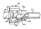
図7を参照すれば、組み立てられた導管12、すなわち、クイックコネクタハウジング20とリテーナ24の貯蔵または輸送時に用いられる一時的なダストカバー120が示されており、これが製造施設から他の施設に輸送されて、ここでクイックコネクタ10と導管12が、空気流デバイス14のポート26に接続される。
【0037】
ダストカバー120は、中空の環状端部124と、直径が僅かに小さい中間部分126とで構成されている。部分124と126は、端部体16のフランジ32上でスナップ係合されるように考えられている。中間部分126の閉鎖端部128は、端部体16の開放端部34を覆う。ほぼ扁平なフィンガータブすなわちハンドル130が、閉鎖端部128からハウジング20の外側端部の外側に突出している。このフィンガータブ130は、組み付け作業員がダストカバー120をハウジング20の端部を通して端部体16と係合させたり、或いは、ダストカバー120を、ハウジング20と導管12をポート26に組み付ける前にハウジング20から取り除くことの両方に用いることができる面を提供する。
【0038】
要約すれば、挿入に要する力が小さくて済み、コンポーネント間を完全にシールされた状態で係合させ、導管とポートの間の完全なシールを表示するばかりでなく、空気流導管と空気流制御デバイスのポートの簡単で迅速な接続を提供する独特の空気流導管のクイックコネクタが開示されている。同時にまた、このクイックコネクタのハウジングとリテーナ部分は、導管12の端部体16の寸法に合わせて組み立てられ製造されるので、1つのアセンブリー中の異なるコンポーネントが、異なる製造業者によって製造されたときに起こる望ましくない製造誤差の形成を防止することができる。
【図面の簡単な説明】
【図1】
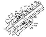
空気流導管を空気流制御デバイスに接続するこの発明の空気流制御クイックコネクタを、その一部が長手方向断面図で示される分解斜視図。
【図2】
一部が組み立てられた状態におけるこの発明のクイックコネクタの斜視図。
【図3】
空気流導管およびポートと完全に組み立てられた状態におけるこの発明のクイックコネクタの一部を斜視図で示す長手方向拡大断面図。
【図4】
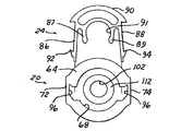
この発明のクイックコネクタの分解斜視図。
【図5】
図4に示すクイックコネクタの分解端面図。
【図6】
完全に組み立てられたこの発明のクイックコネクタの斜視図。
【図7】
可撓性導管に取り付けられ、ダストカバーを装着した梱包状態で示すこの発明のクイックコネクタの底面斜視図。[0001]
Background Air flow conduits typically equipped on automobiles are flexible and are attached by various connectors to air flow control devices such as solenoid valves, air compressors and the like. One such connector is a Legris type connector having fingers with flexible ends that capture the ends of a flexible conduit.
[0002]
However, this type of connector is susceptible to highly fluctuating component manufacturing tolerances that result in fluctuating insertion forces between extreme magnitudes. Further, there is no indication that the seal between the conduit and the connector is completely sealed.
[0003]
As conduits, connectors and pneumatic devices are typically made by different manufacturers, one encounters the problem of tolerance dimensional errors formed between the various parts. The formation of extreme errors creates a "no build" situation.
[0004]
Accordingly, it would be desirable to provide a quick connector devised for an air flow conduit that overcomes the problems encountered with previously devised air flow conduit connectors. At the same time, it not only provides a quick connector that minimizes dimensional errors that create an "assembly impossible" situation, but also has a low insertion force and a completely sealed connection between the conduit and the airflow conduit It would also be desirable to provide a quick connector for an airflow conduit such as mentioned in US Pat.
[0005]
SUMMARY The present invention is an air flow conduit that is advantageously employed in applications where a flexible air flow conduit is mounted in an air flow relationship with an air flow control device such as a solenoid valve, air compressor, or the like. Regarding quick connectors. The quick connector of the present invention finds additional advantageous uses for air actuated devices and air flow conduits employed in motor vehicles.
[0006]
In one aspect of the invention, the connecting structure has one airflow conduit, i.e., a conduit having an end body with an annular enlarged diameter flange spaced from one end of the conduit, and one air utilization conduit. Provided between the device. The connection structure includes a seal member mounted on the conduit adjacent the flange, a port suitably mounted on the airflow device, i.e., a bore extending through the interior, an intermediate tubular portion and an enlarged end portion. And a housing having a housing having a through bore extending between the first and second ends. One transverse aperture is formed in the housing that intersects the through bore. One retainer can be inserted through the transverse bore. The end body of the conduit can be inserted into the housing, the flange of the end body being spaced from the second end of the housing. The port can be inserted through the first end of the housing to an engagement position that is completely sealed with the end body of the conduit, wherein the retainer is connected to one of the retainers. The lip engages the shoulder of the port to prevent the port from coming off the conduit.
[0007]
In one feature, the shoulder of the port is spaced from the first end of the port. The flexible conduit has one inner tube and an outer tube arranged so as to overlap with the inner tube, and an end body arranged in the inner tube extends outward from an end of the outer tube. It is protruding. The end of the outer tube preferably contacts the second end of the housing.
[0008]
One interior surface is formed adjacent the second end of the housing within the through bore. This inner surface biases the flange of the conduit into engagement with the port.
[0009]
In another aspect of the invention, the housing includes a chamber axially spaced from the transverse bore. This chamber receives the connected end body and the end portion of the port.
[0010]
At the same time, the housing also includes a slot extending from a second end partially passing through the housing. The slot receives the end of the conduit for inserting the end of the conduit into the chamber of the housing.
[0011]
This airflow control quick connector overcomes many of the problems encountered with the previously considered airflow quick connectors typically used in automobiles. The quick connector of the present invention provides a completely sealed and robust connection structure between the flexible air conduit and the airflow control device, while at the same time requiring less insertion force and pulling less. Provides a quick connector that requires a great deal of force and displays a complete seal. The quick connector of the present invention also provides an "out of tolerance" or "unassembled" connection for flexible conduits, quick connectors, and acceptable dimensional errors created in airflow control devices. Minimize all impacts from
[0012]
DETAILED DESCRIPTION The various features, advantages, and other utilities of the present invention will become apparent with reference to the following detailed description and accompanying drawings.
[0013]
With particular reference to FIGS. 1-7, an airflow conduit
[0014]
In general, the
[0015]
[0016]
The outer tube or
[0017]
The
[0018]
An
[0019]
As shown in FIG. 1, the stepped end portion in the
[0020]
The stepped bore in the
[0021]
The
[0022]
The
[0023]
As shown in FIGS. 1-7,
[0024]
As described in detail in each of the aforementioned patents, the
[0025]
The
[0026]
Inside the
[0027]
As shown in FIGS. 4 and 5, the first and
[0028]
As shown in FIGS. 1-7, the
[0029]
The sequence of the assembly of the
[0030]
First, in the assembly shown in FIG. 2, the
[0031]
In this position, as shown in FIG. 3, the
[0032]
Next, as shown in FIGS. 3 and 6, the
[0033]
In this position, the
[0034]
The
[0035]
If it is desired to intentionally separate the
[0036]
Referring to FIG. 7, there is shown the assembled
[0037]
The
[0038]
In summary, the insertion force is low and the components are engaged in a completely sealed manner, indicating not only the complete seal between the conduit and the port, but also the airflow conduit and airflow control. A unique air flow conduit quick connector is disclosed that provides simple and quick connection of the ports of the device. At the same time, the housing and retainer portion of this quick connector is assembled and manufactured to the dimensions of the
[Brief description of the drawings]
FIG.
FIG. 2 is an exploded perspective view of the air flow control quick connector of the present invention connecting the air flow conduit to the air flow control device, a part of which is shown in a longitudinal sectional view.
FIG. 2
The perspective view of the quick connector of this invention in the state where a part was assembled.
FIG. 3
FIG. 3 is an enlarged longitudinal cross-sectional view of a portion of the quick connector of the present invention in a fully assembled state with the airflow conduit and port.
FIG. 4
FIG. 2 is an exploded perspective view of the quick connector of the present invention.
FIG. 5
FIG. 5 is an exploded end view of the quick connector shown in FIG. 4.
FIG. 6
FIG. 3 is a perspective view of a fully assembled quick connector of the present invention.
FIG. 7
FIG. 3 is a bottom perspective view of the quick connector of the present invention shown in a package attached to a flexible conduit and fitted with a dust cover.
Claims (8)
フランジに隣接して導管に装着されたシール部材と、
空気流デバイスに適切に装着されたポートとを備えており、前記ポートは、内部を貫通して延出する貫通ボアと、中間管状部分と拡大端部部分の間に形成された肩部を有し、
第1および第2の端部の間に延出する貫通ボアを備えるハウジングと、
貫通ボアと交わるハウジング内に形成された横断方向ボアと、
横断方向ボアを通過して挿入することができるリテーナとを有し、前記リテーナは、1つの側縁部を備えており、
ハウジングの第2の端部から離間した端部体のフランジを備え、ハウジング内に挿入することができる導管の端部体、および、
ハウジングの第1の端部を通って、導管の端部体と完全にシールされる位置まで貫通ボア内に挿入することができるポートを有し、前記リテーナは、ポートが導管から軸方向に移動することを防止するために、リテーナの一方の側縁部をポートの肩部と係合する状態にもたらすように横断方向ボアを通って移動することが可能である、空気導管の対空気流デバイス接続構造体。A conduit end body having an annular enlarged diameter flange spaced from one end of the conduit;
A sealing member mounted on the conduit adjacent to the flange;
A port suitably mounted to the airflow device, the port having a through bore extending therethrough and a shoulder formed between the intermediate tubular portion and the enlarged end portion. And
A housing having a through bore extending between the first and second ends;
A transverse bore formed in the housing that intersects the through bore;
A retainer insertable through a transverse bore, said retainer having one side edge;
An end body of a conduit having an end body flange spaced from a second end of the housing and insertable into the housing; and
A port that can be inserted through the first end of the housing and into the through bore to a position that is completely sealed with the end body of the conduit, the retainer moving the port axially from the conduit; Air conduit device connection that can be moved through the transverse bore to bring one side edge of the retainer into engagement with the shoulder of the port to prevent the device from engaging with the port. Structure.
Applications Claiming Priority (2)
| Application Number | Priority Date | Filing Date | Title |
|---|---|---|---|
| US09/750,628 US6431612B1 (en) | 2000-12-28 | 2000-12-28 | Air flow conduit quick connector |
| PCT/US2001/046385 WO2002053961A2 (en) | 2000-12-28 | 2001-12-03 | Air flow conduit quick connector |
Publications (2)
| Publication Number | Publication Date |
|---|---|
| JP2004537007A true JP2004537007A (en) | 2004-12-09 |
| JP2004537007A5 JP2004537007A5 (en) | 2005-06-23 |
Family
ID=25018618
Family Applications (1)
| Application Number | Title | Priority Date | Filing Date |
|---|---|---|---|
| JP2002554427A Withdrawn JP2004537007A (en) | 2000-12-28 | 2001-12-03 | Quick connector for air flow conduit |
Country Status (5)
| Country | Link |
|---|---|
| US (1) | US6431612B1 (en) |
| EP (1) | EP1348089A2 (en) |
| JP (1) | JP2004537007A (en) |
| AU (1) | AU2002225903A1 (en) |
| WO (1) | WO2002053961A2 (en) |
Families Citing this family (17)
| Publication number | Priority date | Publication date | Assignee | Title |
|---|---|---|---|---|
| JP3871885B2 (en) * | 2001-01-09 | 2007-01-24 | 三桜工業株式会社 | Fitting for piping |
| US6892871B2 (en) * | 2002-03-11 | 2005-05-17 | Cummins-Allison Corp. | Sensor and method for discriminating coins of varied composition, thickness, and diameter |
| US7029036B2 (en) * | 2004-03-09 | 2006-04-18 | Itt Manufacturing Enterprises, Inc. | Rotatable two part quick connection |
| US8113547B2 (en) * | 2002-03-22 | 2012-02-14 | Cooper Standard Automotive Inc. | Snap mount fluid quick connector |
| US6634679B1 (en) * | 2002-04-17 | 2003-10-21 | Itt Manufacturing Enterprises, Inc. | Fluid quick connector with retention clip for flangeless endforms |
| US6866303B2 (en) * | 2002-10-16 | 2005-03-15 | Itt Manufacturing Enterprises, Inc. | Low profile fluid quick connector |
| US7055869B2 (en) * | 2004-01-27 | 2006-06-06 | Itt Manufacturing Enterprises, Inc. | False insertion protection top hat for fluid quick connectors |
| US7761502B2 (en) * | 2004-12-31 | 2010-07-20 | Bea Systems, Inc. | Callback interface for multipools |
| FR2883607A1 (en) * | 2005-03-25 | 2006-09-29 | Raymond Et Cie Soc En Commandi | DEVICE FOR CONNECTING TWO ELEMENTS |
| US7295447B2 (en) * | 2005-06-30 | 2007-11-13 | Dell Products L.P. | Component cam handle |
| US20070126232A1 (en) * | 2005-12-05 | 2007-06-07 | Itt Manufacturing Enterprises, Inc. | Fluid coupling with non-protective coated endform tip |
| US20090058084A1 (en) * | 2007-09-05 | 2009-03-05 | Green Ronald D | Adaptor for quick connect coupling in water supply system |
| US20090145503A1 (en) * | 2007-12-10 | 2009-06-11 | Green Ronald D | Quick connect feature for a fluid connection |
| US8764068B2 (en) | 2012-05-10 | 2014-07-01 | Moen Incorporated | Quick connect coupling with retention feature |
| US9228372B2 (en) * | 2014-02-26 | 2016-01-05 | Maurizio C. Bertato | Fence rail and bracket system |
| WO2016194843A1 (en) * | 2015-05-29 | 2016-12-08 | 株式会社フジキン | Pipe coupling method, component for pipe joint, pipe joint provided with component, fluid controller, fluid control device, and semiconductor manufacturing device |
| TWI679369B (en) * | 2018-01-25 | 2019-12-11 | 效高崗企業有限公司 | Quick joint structure |
Family Cites Families (22)
| Publication number | Priority date | Publication date | Assignee | Title |
|---|---|---|---|---|
| US4009896A (en) * | 1976-05-10 | 1977-03-01 | General Motors Corporation | Quick connect coupling |
| US4526411A (en) * | 1980-10-29 | 1985-07-02 | Proprietary Technology, Inc. | Swivelable quick connector assembly |
| JPS61124786U (en) * | 1984-09-07 | 1986-08-06 | ||
| DE3990401C2 (en) * | 1988-04-26 | 2001-03-22 | Exedy Corp | Release mechanism for a clutch |
| US5090748A (en) * | 1988-07-29 | 1992-02-25 | Usui Kokusai Sangyo Kaisha Ltd. | Small-size piping coupling joint |
| US5219188A (en) * | 1991-01-09 | 1993-06-15 | Sanoh Kogyo Kabushiki Kaisha | Construction for preventing incomplete connection of pipes |
| JP3104929B2 (en) * | 1992-03-11 | 2000-10-30 | 臼井国際産業株式会社 | Small diameter pipe connection fitting |
| US5540463A (en) * | 1992-09-25 | 1996-07-30 | Parker Hannifin Corporation | Couplings for automobile air conditioning system conduits |
| DE4318878A1 (en) * | 1993-06-08 | 1994-12-15 | Kuehner Gmbh & Cie | Refrigerant coupling for connecting refrigerant lines |
| DE4429498C1 (en) * | 1994-08-19 | 1995-08-17 | Rasmussen Gmbh | Plug coupling for hydraulic pipes on e.g. road vehicles |
| US5730481A (en) | 1994-11-04 | 1998-03-24 | Itt Automotive, Inc. | Quick connector with snap-on retainer |
| US5542716A (en) | 1994-11-04 | 1996-08-06 | Itt Corporation | Quick connector with snap-on retainer |
| US5609370A (en) * | 1994-12-02 | 1997-03-11 | Itt Corporation | Positive latch quick connector |
| DE69612232T2 (en) * | 1995-05-17 | 2001-07-12 | Showa Aluminum Corp | Pipe connection |
| US5951063A (en) | 1995-06-07 | 1999-09-14 | Itt Manufacturing Enterprises, Inc. | Quick connector with snap-on retainer having enhanced engagement |
| US5782502A (en) | 1995-12-29 | 1998-07-21 | Itt Automotive, Inc. | Radial-release quick connector |
| DE19619026A1 (en) * | 1996-05-10 | 1997-11-13 | Trinova Gmbh | Quick coupling |
| US5863077A (en) | 1996-12-20 | 1999-01-26 | Itt Automotive, Inc. | Quick connector with snap-on frangible retainer |
| US5797634A (en) * | 1997-06-25 | 1998-08-25 | Stmc-Llc | Quick connect fluid coupling having attachment |
| FR2775509B1 (en) * | 1998-02-27 | 2000-08-11 | Hutchinson | IMPROVEMENT WITH A LOCKABLE CONNECTION FOR A FLUID CONDUIT, PARTICULARLY FOR A MOTOR VEHICLE |
| US6199919B1 (en) * | 1998-03-31 | 2001-03-13 | Tokai Rubber Industries, Ltd. | Tube connecting structure |
| US6149206A (en) * | 1998-06-15 | 2000-11-21 | Dresser Industries, Inc. | Fluid distribution apparatus and method |
-
2000
- 2000-12-28 US US09/750,628 patent/US6431612B1/en not_active Expired - Lifetime
-
2001
- 2001-12-03 JP JP2002554427A patent/JP2004537007A/en not_active Withdrawn
- 2001-12-03 EP EP01995345A patent/EP1348089A2/en not_active Withdrawn
- 2001-12-03 WO PCT/US2001/046385 patent/WO2002053961A2/en active Application Filing
- 2001-12-03 AU AU2002225903A patent/AU2002225903A1/en not_active Abandoned
Also Published As
| Publication number | Publication date |
|---|---|
| US20020084651A1 (en) | 2002-07-04 |
| WO2002053961A3 (en) | 2003-02-27 |
| AU2002225903A1 (en) | 2002-07-16 |
| US6431612B1 (en) | 2002-08-13 |
| WO2002053961A2 (en) | 2002-07-11 |
| EP1348089A2 (en) | 2003-10-01 |
Similar Documents
| Publication | Publication Date | Title |
|---|---|---|
| JP2004537007A (en) | Quick connector for air flow conduit | |
| US6702335B2 (en) | Coupling device of a plug-in coupling and plug-in coupling with such a coupling device | |
| US5897142A (en) | Push-to-release quick connector | |
| US4869534A (en) | Swivelable quick connector | |
| US5951063A (en) | Quick connector with snap-on retainer having enhanced engagement | |
| US6905143B2 (en) | Fluid conduit quick connector and stuffer pack | |
| JP4064929B2 (en) | Fluid quick connector with retaining clip for flangeless end | |
| US8056937B2 (en) | Tube couplings | |
| JP3760251B2 (en) | Quick connector fitting with open mechanism that functions as one piece | |
| US7976071B2 (en) | Fluid connector assembly | |
| EP1304521B1 (en) | Fluid quick connector with radially displaceable locking retainer | |
| US7338093B2 (en) | Connection for fluid lines | |
| EP1559945B1 (en) | False insertion protection top hat for fluid quick connectors | |
| US7029036B2 (en) | Rotatable two part quick connection | |
| US20070132235A1 (en) | Fluid quick connector with integral pivotal retainer | |
| KR100533816B1 (en) | Quick connector with one-way check valve | |
| US6010160A (en) | Quick connector having ring for confirming proper connection | |
| US20050189764A1 (en) | Connector assembly | |
| US6802491B1 (en) | Fluid shut off valve cartridge with quick connection | |
| JPH05118485A (en) | Connector for fluid and sealing assembly in said connector | |
| JP3669222B2 (en) | Quick connector | |
| WO1996030688A1 (en) | Quick connector having ring for confirming proper connection | |
| CA2216649A1 (en) | Quick connector having ring for confirming proper connection |
Legal Events
| Date | Code | Title | Description |
|---|---|---|---|
| A131 | Notification of reasons for refusal |
Free format text: JAPANESE INTERMEDIATE CODE: A131 Effective date: 20060912 |
|
| A601 | Written request for extension of time |
Free format text: JAPANESE INTERMEDIATE CODE: A601 Effective date: 20061212 |
|
| A602 | Written permission of extension of time |
Free format text: JAPANESE INTERMEDIATE CODE: A602 Effective date: 20061226 |
|
| A521 | Request for written amendment filed |
Free format text: JAPANESE INTERMEDIATE CODE: A523 Effective date: 20070312 |
|
| A02 | Decision of refusal |
Free format text: JAPANESE INTERMEDIATE CODE: A02 Effective date: 20070508 |
|
| A521 | Request for written amendment filed |
Free format text: JAPANESE INTERMEDIATE CODE: A523 Effective date: 20070905 |
|
| A761 | Written withdrawal of application |
Free format text: JAPANESE INTERMEDIATE CODE: A761 Effective date: 20071105 |