JP2004530234A - Probe for machine tool - Google Patents
Probe for machine tool Download PDFInfo
- Publication number
- JP2004530234A JP2004530234A JP2003505556A JP2003505556A JP2004530234A JP 2004530234 A JP2004530234 A JP 2004530234A JP 2003505556 A JP2003505556 A JP 2003505556A JP 2003505556 A JP2003505556 A JP 2003505556A JP 2004530234 A JP2004530234 A JP 2004530234A
- Authority
- JP
- Japan
- Prior art keywords
- probe
- pulse
- width modulator
- pulse width
- usart
- Prior art date
- Legal status (The legal status is an assumption and is not a legal conclusion. Google has not performed a legal analysis and makes no representation as to the accuracy of the status listed.)
- Pending
Links
Images

Classifications
-
- G—PHYSICS
- G08—SIGNALLING
- G08C—TRANSMISSION SYSTEMS FOR MEASURED VALUES, CONTROL OR SIMILAR SIGNALS
- G08C19/00—Electric signal transmission systems
- G08C19/16—Electric signal transmission systems in which transmission is by pulses
- G08C19/22—Electric signal transmission systems in which transmission is by pulses by varying the duration of individual pulses
-
- G—PHYSICS
- G01—MEASURING; TESTING
- G01B—MEASURING LENGTH, THICKNESS OR SIMILAR LINEAR DIMENSIONS; MEASURING ANGLES; MEASURING AREAS; MEASURING IRREGULARITIES OF SURFACES OR CONTOURS
- G01B21/00—Measuring arrangements or details thereof, where the measuring technique is not covered by the other groups of this subclass, unspecified or not relevant
- G01B21/02—Measuring arrangements or details thereof, where the measuring technique is not covered by the other groups of this subclass, unspecified or not relevant for measuring length, width, or thickness
- G01B21/04—Measuring arrangements or details thereof, where the measuring technique is not covered by the other groups of this subclass, unspecified or not relevant for measuring length, width, or thickness by measuring coordinates of points
-
- G—PHYSICS
- G01—MEASURING; TESTING
- G01D—MEASURING NOT SPECIALLY ADAPTED FOR A SPECIFIC VARIABLE; ARRANGEMENTS FOR MEASURING TWO OR MORE VARIABLES NOT COVERED IN A SINGLE OTHER SUBCLASS; TARIFF METERING APPARATUS; MEASURING OR TESTING NOT OTHERWISE PROVIDED FOR
- G01D3/00—Indicating or recording apparatus with provision for the special purposes referred to in the subgroups
- G01D3/08—Indicating or recording apparatus with provision for the special purposes referred to in the subgroups with provision for safeguarding the apparatus, e.g. against abnormal operation, against breakdown
Abstract
工作機械のような位置判定装置のプローブが、光測定信号を受信機モジュールに伝送する。本プローブは、電池駆動であり、電池が発光ダイオードに電力を供給し、この発光ダイオードが光測定信号を伝送する。光測定信号はシリアルに伝送されるコードワードを含み、このコードワードは汎用同期/非同期受信機送信機(USART)で生成される。USARTの出力は、USARTの出力と同じ形であるが各パルスの継続時間が減少した出力を有するパルス幅変調器と組み合わされ、発光ダイオードに電力を供給する電池の寿命を増加させる。パルス幅変調器は、USARTのタイミングを設定するようにも使用することができる。A probe of a position determination device, such as a machine tool, transmits the light measurement signal to the receiver module. The probe is battery powered, and the battery supplies power to the light emitting diode, which transmits the light measurement signal. The optical measurement signal includes a serially transmitted codeword, which is generated by a universal synchronous / asynchronous receiver transmitter (UART). The output of the USART is combined with a pulse width modulator having an output of the same shape as the output of the USART, but with a reduced duration of each pulse, to increase the life of the battery that powers the light emitting diodes. A pulse width modulator can also be used to set the timing of the USART.
Description
【技術分野】
【0001】
本発明は、座標測定機械、測定ロボット、および特に工作機械のような位置判定装置で使用するプローブに関する。
【背景技術】
【0002】
そのようなプローブの例は特許文献1に示されている。プローブと工作機械のコントローラとの間に無線信号伝送がある工作機械で使用するためのプローブは、特許文献2および特許文献3に示されている。
【0003】
【特許文献1】
米国特許第4,153,998号明細書
【特許文献2】
欧州特許第337669号明細書
【特許文献3】
欧州特許第337670号明細書
【発明の開示】
【発明が解決しようとする課題】
【0004】
工作機械で使用するとき、そのようなプローブは一般に電池駆動である。このプローブは測定信号を受信機モジュールに光学的に伝送することができるが、この光学的な情報送信時の電力消費のために、電池寿命は短くなる。
【課題を解決するための手段】
【0005】
本発明は、
信号を生成する信号生成手段と、
信号生成手段で生成された信号を光パルスの形で受信機モジュールに伝送する信号伝送手段と
を備えた位置判定装置用プローブにおいて、
パルス幅変調器が各パルスの継続時間を減少するように設けられた
ことを特徴とするプローブを提供する。
【0006】
好ましくは、信号生成手段は、汎用同期/非同期受信機送信機を含む。パルス幅変調器は、汎用同期/非同期受信機送信機(USART)のタイミングを制御することができる。
【0007】
好ましくは、プローブは電池駆動である。光パルスは、LEDによって生成することができる。
【0008】
以下、添付の図面を参照して、本発明の好適実施形態を説明する。
【発明を実施するための最良の形態】
【0009】
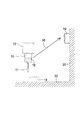
図1を参照すると、プローブ10は、通常の切削工具と交換可能に工作機械のスピンドル12に取り付けられている。スピンドル12は、工作機械のテーブルまたはベッド22にクランプ(clamp)された被加工物(workpiece)14に対して、プローブを3次元のx、y、zで動かすことができる。プローブのスタイラス11と被加工物との間の接触で測定を行う。プローブからの測定信号は、矢印16で示すように、工作機械の固定構造20に取り付けられた受信機モジュール19に光学的に伝送される。プローブ10は、電池駆動である。光測定信号を伝送するために使用される窓18の内側にあるLEDに、電池が電力を供給する。
【0010】
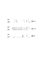
図1に矢印16で示す光測定信号は、シリアルに伝送されるコードワード(codeword)を含む。各コードワードは8ビット長であり、一連のオン/オフのパルスを含む。これらのコードワードは、汎用同期/非同期受信機送信機(USART)を備える信号生成手段で生成される。このようにして形成されたコードワードの一部を図2Aに示す。一般に、各パルスは8マイクロ秒の長さであり、16ミリ秒ごとに新しいコードワードを伝送することができる。
【0011】
汎用同期/非同期受信機送信機(USART)だけを使用してコードワードを生成することには、各パルスが比較的長いので高電力消費となり、したがって電池寿命が短くなるという不都合がある。
【0012】
この不都合を克服するために、汎用同期/非同期受信機送信機(USART)をパルス幅変調器と組み合わせる。図2Bに示すように、パルス幅変調器によって、汎用同期/非同期受信機送信機(USART)で生成されるものに比べて、パルス長がより短くかつパルス間の時間間隔がより短い規則的な一連のパルスが生成される。パルス間の時間は一般に8マイクロ秒であり、パルス長は一般に2マイクロ秒である。汎用同期/非同期受信機送信機(USART)の出力をパルス幅変調器の出力と組み合わせて、伝送用の細かく切られた(chopped)出力を供給する。図2Cに示すように、この結果として得られる出力の形は、図2Aに示す汎用同期/非同期受信機送信機(USART)の出力の形と同じであるが、各オンパルスの継続時間は、パルス幅変調器の継続時間に等しいように減少している。これによって、各LEDのフラッシュの継続時間が減少し、したがってシステムの電力消費が減少する。その結果、電池寿命は増す。
【0013】
汎用同期/非同期受信機送信機(USART)と組み合わせてパルス幅変調器を使用することには、第2の有利点がある。パルス幅変調器の無い以前のシステムでは、マイクロプロセッサがタイミングとパルスの連続の両方を制御しなければならないが、システムにパルス幅変調器が組み込まれるとき、これを使用して汎用同期/非同期受信機送信機(USART)のタイミングを設定することができる。すなわち、パルス幅変調器はタイミング用のシリアルクロックとして動作する。マイクロプロセッサは汎用同期/非同期受信機送信機(USART)にオン/オフ情報を送るために必要とされるだけであるので、マイクロプロセッサの使用はより少なくなり、したがってマルチタスキング(multi-tasking)が改善される。
【0014】
パルス幅変調器は、モータ制御またはディジタル/アナログ変換のような他の用途のために、プローブにすでに組み込まれているかもしれない。したがって、プローブ中の既存の部品をシステムに使用することで、部品コストが低減される。
【0015】
図3は、シリアルコードワードの形成を示す説明図である。プローブのマイクロプロセッサ30は、パルス幅変調器32と汎用同期/非同期受信機送信機(USART)34の形の信号生成手段とを内蔵している。パルス幅変調器32からの出力36が、汎用同期/非同期受信機送信機(USART)のタイミングを制御する。パルス幅変調器32および汎用同期/非同期受信機送信機(USART)34の出力38、40は、シリアルコードワード44を形成するようにANDゲート42で組み合わされる。このシリアルコードワードは、LEDまたは他の信号伝送手段から外部受信機に伝送される。
【図面の簡単な説明】
【0016】
【図1】工作機械のプローブを示す概略図である。
【図2】図2Aは汎用同期/非同期受信機送信機(USART)で形成される光パルスのコードワードの一部、図2Bはパルス幅変調器の出力、図2Cは組み合わされた汎用同期/非同期受信機送信機(USART)およびパルス幅変調器の出力を示す図である。
【図3】シリアルコードワードの形成を示す説明図である。【Technical field】
[0001]
The present invention relates to a probe for use in a position measuring device such as a coordinate measuring machine, a measuring robot, and especially a machine tool.
[Background Art]
[0002]
An example of such a probe is shown in US Pat. Probes for use on machine tools with wireless signal transmission between the probe and the controller of the machine tool are shown in US Pat.
[0003]
[Patent Document 1]
US Patent No. 4,153,998 [Patent Document 2]
European Patent No. 337669 [Patent Document 3]
European Patent No. 337670 [Disclosure of the Invention]
[Problems to be solved by the invention]
[0004]
When used in machine tools, such probes are generally battery powered. Although this probe can optically transmit the measurement signal to the receiver module, the battery life is reduced due to the power consumption during this optical information transmission.
[Means for Solving the Problems]
[0005]
The present invention
Signal generation means for generating a signal,
A signal transmission means for transmitting the signal generated by the signal generation means to the receiver module in the form of an optical pulse;
A probe is provided wherein a pulse width modulator is provided to reduce the duration of each pulse.
[0006]
Preferably, the signal generating means includes a universal synchronous / asynchronous receiver transmitter. A pulse width modulator can control the timing of a universal synchronous / asynchronous receiver transmitter (UART).
[0007]
Preferably, the probe is battery powered. The light pulse can be generated by an LED.
[0008]
Hereinafter, preferred embodiments of the present invention will be described with reference to the accompanying drawings.
BEST MODE FOR CARRYING OUT THE INVENTION
[0009]
Referring to FIG. 1, a
[0010]
The light measurement signal indicated by
[0011]
Generating codewords using only a universal synchronous / asynchronous receiver transmitter (USART) has the disadvantage of high power consumption due to the relatively long duration of each pulse, and thus reduced battery life.
[0012]
To overcome this disadvantage, a universal synchronous / asynchronous receiver transmitter (USAT) is combined with a pulse width modulator. As shown in FIG. 2B, the pulse width modulator has a shorter pulse length and a shorter time interval between pulses, as compared to that generated by a universal synchronous / asynchronous receiver transmitter (USART). A series of pulses is generated. The time between pulses is typically 8 microseconds and the pulse length is typically 2 microseconds. The output of a universal synchronous / asynchronous receiver transmitter (UART) is combined with the output of a pulse width modulator to provide a chopped output for transmission. As shown in FIG. 2C, the shape of the resulting output is the same as that of the universal synchronous / asynchronous receiver transmitter (UART) shown in FIG. 2A, except that the duration of each on-pulse is It has been reduced to equal the duration of the width modulator. This reduces the duration of each LED's flash, and thus the power consumption of the system. As a result, battery life is increased.
[0013]
The use of a pulse width modulator in combination with a universal synchronous / asynchronous receiver transmitter (UART) has a second advantage. In previous systems without pulse width modulators, the microprocessor had to control both timing and pulse continuity, but when a pulse width modulator was incorporated into the system, it was used to provide universal synchronous / asynchronous reception. Transmitter (UART) timing can be set. That is, the pulse width modulator operates as a serial clock for timing. Because the microprocessor is only needed to send on / off information to the universal synchronous / asynchronous receiver transmitter (USAT), the use of the microprocessor is less and therefore multi-tasking. Is improved.
[0014]
The pulse width modulator may already be built into the probe for other applications such as motor control or digital / analog conversion. Thus, using the existing components in the probe for the system reduces component costs.
[0015]
FIG. 3 is an explanatory diagram showing the formation of a serial codeword. The
[Brief description of the drawings]
[0016]
FIG. 1 is a schematic view showing a probe of a machine tool.
FIG. 2A is a portion of a codeword of an optical pulse formed by a universal synchronous / asynchronous receiver transmitter (USART), FIG. 2B is the output of a pulse width modulator, and FIG. FIG. 3 is a diagram illustrating outputs of an asynchronous receiver transmitter (USART) and a pulse width modulator.
FIG. 3 is an explanatory diagram showing the formation of a serial codeword.
Claims (5)
前記信号生成手段によって生成された信号を光パルスの形で受信機モジュールに伝送する信号伝送手段と
を備えた位置判定装置用プローブにおいて、
パルス幅変調器が各パルスの継続時間を減少するように設けられた
ことを特徴とするプローブ。Signal generation means for generating a signal,
A signal transmission means for transmitting the signal generated by the signal generation means to the receiver module in the form of an optical pulse;
A probe wherein a pulse width modulator is provided to reduce the duration of each pulse.
Applications Claiming Priority (2)
| Application Number | Priority Date | Filing Date | Title |
|---|---|---|---|
| GBGB0114765.1A GB0114765D0 (en) | 2001-06-16 | 2001-06-16 | Machine tool probe |
| PCT/GB2002/002482 WO2002103283A1 (en) | 2001-06-16 | 2002-06-14 | Machine tool probe |
Publications (2)
| Publication Number | Publication Date |
|---|---|
| JP2004530234A true JP2004530234A (en) | 2004-09-30 |
| JP2004530234A5 JP2004530234A5 (en) | 2006-01-05 |
Family
ID=9916777
Family Applications (1)
| Application Number | Title | Priority Date | Filing Date |
|---|---|---|---|
| JP2003505556A Pending JP2004530234A (en) | 2001-06-16 | 2002-06-14 | Probe for machine tool |
Country Status (5)
| Country | Link |
|---|---|
| US (1) | US6860026B2 (en) |
| EP (1) | EP1397637A1 (en) |
| JP (1) | JP2004530234A (en) |
| GB (1) | GB0114765D0 (en) |
| WO (1) | WO2002103283A1 (en) |
Families Citing this family (6)
| Publication number | Priority date | Publication date | Assignee | Title |
|---|---|---|---|---|
| GB0518078D0 (en) * | 2005-09-06 | 2005-10-12 | Renishaw Plc | Signal transmission system |
| EP2028439A1 (en) * | 2007-07-26 | 2009-02-25 | Renishaw plc | Deactivatable measurement apparatus |
| DE102007054838A1 (en) * | 2007-11-16 | 2009-05-20 | Dr. Johannes Heidenhain Gmbh | Touch probe and method for operating a touch probe |
| JP5262630B2 (en) * | 2008-12-01 | 2013-08-14 | 富士通株式会社 | Clock generation circuit having self-test circuit |
| DE102009060784A1 (en) * | 2009-12-22 | 2011-06-30 | Carl Zeiss 3D Automation GmbH, 73447 | Stylus and probe for a coordinate measuring machine |
| GB201700879D0 (en) | 2017-01-18 | 2017-03-01 | Renishaw Plc | Machine tool apparatus |
Family Cites Families (9)
| Publication number | Priority date | Publication date | Assignee | Title |
|---|---|---|---|---|
| US4153998A (en) * | 1972-09-21 | 1979-05-15 | Rolls-Royce (1971) Limited | Probes |
| GB2137457B (en) * | 1983-03-17 | 1986-07-30 | Masahiro Aruga | Recording and reconstructing digital data |
| US5150529A (en) * | 1988-04-12 | 1992-09-29 | Renishaw Plc | Signal transmission system for machine tools, inspection machines, and the like |
| GB8808612D0 (en) | 1988-04-12 | 1988-05-11 | Renishaw Plc | Signal transmission system for machine tools inspection machines &c |
| IT1279590B1 (en) * | 1995-05-11 | 1997-12-16 | Marposs Spa | SYSTEM AND METHOD OF TRANSMISSION OF SIGNALS VIA ETHER BETWEEN A CONTROL HEAD AND A REMOTE RECEIVER |
| US5777562A (en) * | 1996-08-19 | 1998-07-07 | Hoffman; David J. | Centering device and method for centering |
| US6118567A (en) * | 1997-09-30 | 2000-09-12 | Motorola, Inc. | Efficient encoding and detection method and device for binary intensity modulated optical data signals |
| IT1309248B1 (en) * | 1999-05-13 | 2002-01-16 | Marposs Spa | SYSTEM TO DETECT LINEAR DIMENSIONS OF MECHANICAL PIECES, WITH UNIT OF RECEIVING SIGNALS VIA ETHER |
| JP3763124B2 (en) * | 2001-05-31 | 2006-04-05 | 株式会社ミツトヨ | Signal processing apparatus and signal processing method for touch signal probe |
-
2001
- 2001-06-16 GB GBGB0114765.1A patent/GB0114765D0/en not_active Ceased
-
2002
- 2002-06-14 EP EP02738332A patent/EP1397637A1/en not_active Withdrawn
- 2002-06-14 WO PCT/GB2002/002482 patent/WO2002103283A1/en active Application Filing
- 2002-06-14 JP JP2003505556A patent/JP2004530234A/en active Pending
- 2002-06-14 US US10/477,894 patent/US6860026B2/en not_active Expired - Lifetime
Also Published As
| Publication number | Publication date |
|---|---|
| EP1397637A1 (en) | 2004-03-17 |
| US20040134085A1 (en) | 2004-07-15 |
| WO2002103283A1 (en) | 2002-12-27 |
| GB0114765D0 (en) | 2001-08-08 |
| US6860026B2 (en) | 2005-03-01 |
Similar Documents
| Publication | Publication Date | Title |
|---|---|---|
| US10799997B2 (en) | Optical display device unit for use in an external application unit | |
| DK0899064T3 (en) | Power-driven tool with interchangeable tool head | |
| EP1326239A3 (en) | Information recording device | |
| DE50107754D1 (en) | ELECTROMOTICALLY DRIVEN TOOTHBRUSH WITH SIGNALING DEVICE | |
| DE58908759D1 (en) | Optical transmitter with a laser diode. | |
| JP2004530234A (en) | Probe for machine tool | |
| EP0938196A3 (en) | Optical transmitter and optical transmitting apparatus using the same | |
| DE60142819D1 (en) | Contactless rotary connector | |
| WO2001005559A3 (en) | Improved power tools | |
| CA2428590A1 (en) | Low power laser driver | |
| TW200516580A (en) | Laser driving device | |
| EP1251632A3 (en) | Circuit for generating three-phase PWM signal | |
| JP2004530234A5 (en) | ||
| CN210838443U (en) | Control circuit of laser BIAS current, light source module and quantum communication equipment | |
| CN220833210U (en) | Full-automatic toothbrush trigger device and full-automatic toothbrush | |
| JPS6160916U (en) | ||
| JPS6120118A (en) | Keyboard | |
| IL164278A0 (en) | Method and device for producing an optical link with laser pulses | |
| JPS63145109U (en) | ||
| WO1999000764A3 (en) | Two-level semiconductor laser driver | |
| DE60312771D1 (en) | Motor pump group with sensor power supply via the pump power cable | |
| JPS6082400U (en) | Mobile object identification device | |
| JPH0148703B2 (en) | ||
| WO2000059264A3 (en) | Optical microphone apparatus | |
| JPH04113004U (en) | touch sensor |
Legal Events
| Date | Code | Title | Description |
|---|---|---|---|
| A521 | Request for written amendment filed |
Free format text: JAPANESE INTERMEDIATE CODE: A523 Effective date: 20050614 |
|
| A621 | Written request for application examination |
Free format text: JAPANESE INTERMEDIATE CODE: A621 Effective date: 20050614 |
|
| A977 | Report on retrieval |
Free format text: JAPANESE INTERMEDIATE CODE: A971007 Effective date: 20080318 |
|
| A131 | Notification of reasons for refusal |
Free format text: JAPANESE INTERMEDIATE CODE: A131 Effective date: 20080325 |
|
| A601 | Written request for extension of time |
Free format text: JAPANESE INTERMEDIATE CODE: A601 Effective date: 20080625 |
|
| A602 | Written permission of extension of time |
Free format text: JAPANESE INTERMEDIATE CODE: A602 Effective date: 20080702 |
|
| A521 | Request for written amendment filed |
Free format text: JAPANESE INTERMEDIATE CODE: A523 Effective date: 20080825 |
|
| A02 | Decision of refusal |
Free format text: JAPANESE INTERMEDIATE CODE: A02 Effective date: 20090130 |