JP2004526032A - Microstructured catalyst beds for three-phase chemical processing - Google Patents
Microstructured catalyst beds for three-phase chemical processing Download PDFInfo
- Publication number
- JP2004526032A JP2004526032A JP2002577758A JP2002577758A JP2004526032A JP 2004526032 A JP2004526032 A JP 2004526032A JP 2002577758 A JP2002577758 A JP 2002577758A JP 2002577758 A JP2002577758 A JP 2002577758A JP 2004526032 A JP2004526032 A JP 2004526032A
- Authority
- JP
- Japan
- Prior art keywords
- liquid
- catalyst
- reaction
- gas
- range
- Prior art date
- Legal status (The legal status is an assumption and is not a legal conclusion. Google has not performed a legal analysis and makes no representation as to the accuracy of the status listed.)
- Pending
Links
- 239000003054 catalyst Substances 0.000 title claims description 254
- 238000012993 chemical processing Methods 0.000 title description 2
- 239000007788 liquid Substances 0.000 claims abstract description 148
- 238000006243 chemical reaction Methods 0.000 claims abstract description 132
- 238000005984 hydrogenation reaction Methods 0.000 claims abstract description 61
- 239000011949 solid catalyst Substances 0.000 claims abstract description 10
- 238000000034 method Methods 0.000 claims description 56
- 239000007789 gas Substances 0.000 claims description 45
- UFHFLCQGNIYNRP-UHFFFAOYSA-N Hydrogen Chemical compound [H][H] UFHFLCQGNIYNRP-UHFFFAOYSA-N 0.000 claims description 23
- 150000002430 hydrocarbons Chemical class 0.000 claims description 23
- 230000008569 process Effects 0.000 claims description 22
- 150000001336 alkenes Chemical class 0.000 claims description 20
- JRZJOMJEPLMPRA-UHFFFAOYSA-N olefin Natural products CCCCCCCC=C JRZJOMJEPLMPRA-UHFFFAOYSA-N 0.000 claims description 17
- 239000001257 hydrogen Substances 0.000 claims description 12
- 229910052739 hydrogen Inorganic materials 0.000 claims description 12
- 150000004945 aromatic hydrocarbons Chemical class 0.000 claims description 5
- 150000002431 hydrogen Chemical class 0.000 claims description 5
- 229930195735 unsaturated hydrocarbon Natural products 0.000 claims description 5
- 239000011248 coating agent Substances 0.000 claims description 4
- 238000000576 coating method Methods 0.000 claims description 4
- 239000006185 dispersion Substances 0.000 claims description 3
- 239000000919 ceramic Substances 0.000 claims 1
- 239000000376 reactant Substances 0.000 abstract description 31
- 238000011282 treatment Methods 0.000 abstract description 9
- 239000000126 substance Substances 0.000 abstract description 5
- YXFVVABEGXRONW-UHFFFAOYSA-N Toluene Chemical compound CC1=CC=CC=C1 YXFVVABEGXRONW-UHFFFAOYSA-N 0.000 description 72
- 241000264877 Hippospongia communis Species 0.000 description 66
- KWKAKUADMBZCLK-UHFFFAOYSA-N 1-octene Chemical compound CCCCCCC=C KWKAKUADMBZCLK-UHFFFAOYSA-N 0.000 description 56
- TVMXDCGIABBOFY-UHFFFAOYSA-N n-Octanol Natural products CCCCCCCC TVMXDCGIABBOFY-UHFFFAOYSA-N 0.000 description 40
- 230000000694 effects Effects 0.000 description 37
- PPBRXRYQALVLMV-UHFFFAOYSA-N Styrene Chemical compound C=CC1=CC=CC=C1 PPBRXRYQALVLMV-UHFFFAOYSA-N 0.000 description 32
- 239000008188 pellet Substances 0.000 description 29
- 229930195733 hydrocarbon Natural products 0.000 description 20
- 239000004215 Carbon black (E152) Substances 0.000 description 17
- 230000008901 benefit Effects 0.000 description 16
- UAEPNZWRGJTJPN-UHFFFAOYSA-N methylcyclohexane Chemical compound CC1CCCCC1 UAEPNZWRGJTJPN-UHFFFAOYSA-N 0.000 description 16
- 239000000203 mixture Substances 0.000 description 15
- 238000012360 testing method Methods 0.000 description 15
- PNEYBMLMFCGWSK-UHFFFAOYSA-N aluminium oxide Inorganic materials [O-2].[O-2].[O-2].[Al+3].[Al+3] PNEYBMLMFCGWSK-UHFFFAOYSA-N 0.000 description 14
- YNQLUTRBYVCPMQ-UHFFFAOYSA-N Ethylbenzene Chemical compound CCC1=CC=CC=C1 YNQLUTRBYVCPMQ-UHFFFAOYSA-N 0.000 description 12
- 239000000047 product Substances 0.000 description 11
- 238000013461 design Methods 0.000 description 9
- 239000012071 phase Substances 0.000 description 9
- 239000000758 substrate Substances 0.000 description 9
- 230000007423 decrease Effects 0.000 description 8
- 238000011068 loading method Methods 0.000 description 8
- GYNNXHKOJHMOHS-UHFFFAOYSA-N methyl-cycloheptane Natural products CC1CCCCCC1 GYNNXHKOJHMOHS-UHFFFAOYSA-N 0.000 description 8
- PXHVJJICTQNCMI-UHFFFAOYSA-N nickel Substances [Ni] PXHVJJICTQNCMI-UHFFFAOYSA-N 0.000 description 7
- QTBSBXVTEAMEQO-UHFFFAOYSA-N Acetic acid Chemical compound CC(O)=O QTBSBXVTEAMEQO-UHFFFAOYSA-N 0.000 description 6
- 230000003197 catalytic effect Effects 0.000 description 6
- 238000006555 catalytic reaction Methods 0.000 description 6
- 239000000843 powder Substances 0.000 description 5
- YTPLMLYBLZKORZ-UHFFFAOYSA-N Thiophene Chemical compound C=1C=CSC=1 YTPLMLYBLZKORZ-UHFFFAOYSA-N 0.000 description 4
- 125000003118 aryl group Chemical group 0.000 description 4
- 239000011324 bead Substances 0.000 description 4
- 150000005194 ethylbenzenes Chemical class 0.000 description 4
- 239000012263 liquid product Substances 0.000 description 4
- 239000000463 material Substances 0.000 description 4
- 230000002829 reductive effect Effects 0.000 description 4
- 238000012546 transfer Methods 0.000 description 4
- 230000001419 dependent effect Effects 0.000 description 3
- 238000009826 distribution Methods 0.000 description 3
- 238000011065 in-situ storage Methods 0.000 description 3
- 238000012545 processing Methods 0.000 description 3
- 238000007670 refining Methods 0.000 description 3
- 229910001220 stainless steel Inorganic materials 0.000 description 3
- 239000010935 stainless steel Substances 0.000 description 3
- 229910052717 sulfur Inorganic materials 0.000 description 3
- FCEHBMOGCRZNNI-UHFFFAOYSA-N 1-benzothiophene Chemical compound C1=CC=C2SC=CC2=C1 FCEHBMOGCRZNNI-UHFFFAOYSA-N 0.000 description 2
- 229910002651 NO3 Inorganic materials 0.000 description 2
- NHNBFGGVMKEFGY-UHFFFAOYSA-N Nitrate Chemical compound [O-][N+]([O-])=O NHNBFGGVMKEFGY-UHFFFAOYSA-N 0.000 description 2
- NINIDFKCEFEMDL-UHFFFAOYSA-N Sulfur Chemical compound [S] NINIDFKCEFEMDL-UHFFFAOYSA-N 0.000 description 2
- 239000004568 cement Substances 0.000 description 2
- 238000006757 chemical reactions by type Methods 0.000 description 2
- 230000002860 competitive effect Effects 0.000 description 2
- 229910052878 cordierite Inorganic materials 0.000 description 2
- HGCIXCUEYOPUTN-UHFFFAOYSA-N cyclohexene Chemical compound C1CCC=CC1 HGCIXCUEYOPUTN-UHFFFAOYSA-N 0.000 description 2
- 230000003247 decreasing effect Effects 0.000 description 2
- IYYZUPMFVPLQIF-UHFFFAOYSA-N dibenzothiophene Chemical compound C1=CC=C2C3=CC=CC=C3SC2=C1 IYYZUPMFVPLQIF-UHFFFAOYSA-N 0.000 description 2
- 239000003085 diluting agent Substances 0.000 description 2
- JSKIRARMQDRGJZ-UHFFFAOYSA-N dimagnesium dioxido-bis[(1-oxido-3-oxo-2,4,6,8,9-pentaoxa-1,3-disila-5,7-dialuminabicyclo[3.3.1]nonan-7-yl)oxy]silane Chemical compound [Mg++].[Mg++].[O-][Si]([O-])(O[Al]1O[Al]2O[Si](=O)O[Si]([O-])(O1)O2)O[Al]1O[Al]2O[Si](=O)O[Si]([O-])(O1)O2 JSKIRARMQDRGJZ-UHFFFAOYSA-N 0.000 description 2
- 238000005470 impregnation Methods 0.000 description 2
- 230000006872 improvement Effects 0.000 description 2
- 230000000670 limiting effect Effects 0.000 description 2
- 239000007791 liquid phase Substances 0.000 description 2
- 238000004519 manufacturing process Methods 0.000 description 2
- 239000002184 metal Substances 0.000 description 2
- 229910052751 metal Inorganic materials 0.000 description 2
- 229910000480 nickel oxide Inorganic materials 0.000 description 2
- 150000002828 nitro derivatives Chemical class 0.000 description 2
- GNRSAWUEBMWBQH-UHFFFAOYSA-N oxonickel Chemical compound [Ni]=O GNRSAWUEBMWBQH-UHFFFAOYSA-N 0.000 description 2
- 239000002245 particle Substances 0.000 description 2
- 239000007787 solid Substances 0.000 description 2
- 239000000243 solution Substances 0.000 description 2
- 239000011593 sulfur Substances 0.000 description 2
- 229930192474 thiophene Natural products 0.000 description 2
- 238000009736 wetting Methods 0.000 description 2
- 229910000831 Steel Inorganic materials 0.000 description 1
- 230000009471 action Effects 0.000 description 1
- 239000011149 active material Substances 0.000 description 1
- 239000000654 additive Substances 0.000 description 1
- 230000000996 additive effect Effects 0.000 description 1
- 150000001345 alkine derivatives Chemical class 0.000 description 1
- 238000013459 approach Methods 0.000 description 1
- 239000007864 aqueous solution Substances 0.000 description 1
- 150000001491 aromatic compounds Chemical class 0.000 description 1
- -1 aromatic sulfur compounds Chemical class 0.000 description 1
- 238000001354 calcination Methods 0.000 description 1
- 229910010293 ceramic material Inorganic materials 0.000 description 1
- 230000008859 change Effects 0.000 description 1
- 238000003889 chemical engineering Methods 0.000 description 1
- 238000001311 chemical methods and process Methods 0.000 description 1
- 238000004939 coking Methods 0.000 description 1
- 238000002485 combustion reaction Methods 0.000 description 1
- 150000001875 compounds Chemical class 0.000 description 1
- 238000010276 construction Methods 0.000 description 1
- 230000001276 controlling effect Effects 0.000 description 1
- 230000000875 corresponding effect Effects 0.000 description 1
- 230000008878 coupling Effects 0.000 description 1
- 238000010168 coupling process Methods 0.000 description 1
- 238000005859 coupling reaction Methods 0.000 description 1
- 125000000753 cycloalkyl group Chemical group 0.000 description 1
- 238000011161 development Methods 0.000 description 1
- 238000010790 dilution Methods 0.000 description 1
- 239000012895 dilution Substances 0.000 description 1
- KZHJGOXRZJKJNY-UHFFFAOYSA-N dioxosilane;oxo(oxoalumanyloxy)alumane Chemical compound O=[Si]=O.O=[Si]=O.O=[Al]O[Al]=O.O=[Al]O[Al]=O.O=[Al]O[Al]=O KZHJGOXRZJKJNY-UHFFFAOYSA-N 0.000 description 1
- 238000001035 drying Methods 0.000 description 1
- 238000005516 engineering process Methods 0.000 description 1
- 230000002349 favourable effect Effects 0.000 description 1
- 239000012530 fluid Substances 0.000 description 1
- 239000000446 fuel Substances 0.000 description 1
- 125000000524 functional group Chemical group 0.000 description 1
- 238000010574 gas phase reaction Methods 0.000 description 1
- 230000005484 gravity Effects 0.000 description 1
- 230000003993 interaction Effects 0.000 description 1
- 230000014759 maintenance of location Effects 0.000 description 1
- 229910044991 metal oxide Inorganic materials 0.000 description 1
- 150000004706 metal oxides Chemical class 0.000 description 1
- 150000002739 metals Chemical class 0.000 description 1
- 238000002156 mixing Methods 0.000 description 1
- 238000012986 modification Methods 0.000 description 1
- 230000004048 modification Effects 0.000 description 1
- 229910052863 mullite Inorganic materials 0.000 description 1
- 150000002815 nickel Chemical class 0.000 description 1
- 229910052759 nickel Inorganic materials 0.000 description 1
- KBJMLQFLOWQJNF-UHFFFAOYSA-N nickel(ii) nitrate Chemical compound [Ni+2].[O-][N+]([O-])=O.[O-][N+]([O-])=O KBJMLQFLOWQJNF-UHFFFAOYSA-N 0.000 description 1
- QJGQUHMNIGDVPM-UHFFFAOYSA-N nitrogen group Chemical group [N] QJGQUHMNIGDVPM-UHFFFAOYSA-N 0.000 description 1
- 230000001151 other effect Effects 0.000 description 1
- 230000003647 oxidation Effects 0.000 description 1
- 238000007254 oxidation reaction Methods 0.000 description 1
- 238000012856 packing Methods 0.000 description 1
- 230000036961 partial effect Effects 0.000 description 1
- 230000000737 periodic effect Effects 0.000 description 1
- 238000000053 physical method Methods 0.000 description 1
- 239000011148 porous material Substances 0.000 description 1
- 238000002360 preparation method Methods 0.000 description 1
- 238000004064 recycling Methods 0.000 description 1
- 238000011160 research Methods 0.000 description 1
- 238000012552 review Methods 0.000 description 1
- 238000010517 secondary reaction Methods 0.000 description 1
- 239000002893 slag Substances 0.000 description 1
- 239000002002 slurry Substances 0.000 description 1
- 239000011343 solid material Substances 0.000 description 1
- 239000010959 steel Substances 0.000 description 1
- 238000006557 surface reaction Methods 0.000 description 1
- 238000010998 test method Methods 0.000 description 1
- 229910052723 transition metal Inorganic materials 0.000 description 1
- 229910000314 transition metal oxide Inorganic materials 0.000 description 1
- 150000003624 transition metals Chemical class 0.000 description 1
- 238000009827 uniform distribution Methods 0.000 description 1
- 239000011800 void material Substances 0.000 description 1
- XLYOFNOQVPJJNP-UHFFFAOYSA-N water Substances O XLYOFNOQVPJJNP-UHFFFAOYSA-N 0.000 description 1
- 238000009279 wet oxidation reaction Methods 0.000 description 1
Images


Classifications
-
- B—PERFORMING OPERATIONS; TRANSPORTING
- B01—PHYSICAL OR CHEMICAL PROCESSES OR APPARATUS IN GENERAL
- B01J—CHEMICAL OR PHYSICAL PROCESSES, e.g. CATALYSIS OR COLLOID CHEMISTRY; THEIR RELEVANT APPARATUS
- B01J35/00—Catalysts, in general, characterised by their form or physical properties
- B01J35/50—Catalysts, in general, characterised by their form or physical properties characterised by their shape or configuration
- B01J35/56—Foraminous structures having flow-through passages or channels, e.g. grids or three-dimensional monoliths
-
- B—PERFORMING OPERATIONS; TRANSPORTING
- B01—PHYSICAL OR CHEMICAL PROCESSES OR APPARATUS IN GENERAL
- B01J—CHEMICAL OR PHYSICAL PROCESSES, e.g. CATALYSIS OR COLLOID CHEMISTRY; THEIR RELEVANT APPARATUS
- B01J19/00—Chemical, physical or physico-chemical processes in general; Their relevant apparatus
- B01J19/24—Stationary reactors without moving elements inside
- B01J19/248—Reactors comprising multiple separated flow channels
- B01J19/2485—Monolithic reactors
-
- B—PERFORMING OPERATIONS; TRANSPORTING
- B01—PHYSICAL OR CHEMICAL PROCESSES OR APPARATUS IN GENERAL
- B01J—CHEMICAL OR PHYSICAL PROCESSES, e.g. CATALYSIS OR COLLOID CHEMISTRY; THEIR RELEVANT APPARATUS
- B01J23/00—Catalysts comprising metals or metal oxides or hydroxides, not provided for in group B01J21/00
- B01J23/70—Catalysts comprising metals or metal oxides or hydroxides, not provided for in group B01J21/00 of the iron group metals or copper
- B01J23/74—Iron group metals
- B01J23/755—Nickel
-
- C—CHEMISTRY; METALLURGY
- C07—ORGANIC CHEMISTRY
- C07C—ACYCLIC OR CARBOCYCLIC COMPOUNDS
- C07C5/00—Preparation of hydrocarbons from hydrocarbons containing the same number of carbon atoms
- C07C5/02—Preparation of hydrocarbons from hydrocarbons containing the same number of carbon atoms by hydrogenation
- C07C5/03—Preparation of hydrocarbons from hydrocarbons containing the same number of carbon atoms by hydrogenation of non-aromatic carbon-to-carbon double bonds
-
- C—CHEMISTRY; METALLURGY
- C07—ORGANIC CHEMISTRY
- C07C—ACYCLIC OR CARBOCYCLIC COMPOUNDS
- C07C5/00—Preparation of hydrocarbons from hydrocarbons containing the same number of carbon atoms
- C07C5/02—Preparation of hydrocarbons from hydrocarbons containing the same number of carbon atoms by hydrogenation
- C07C5/10—Preparation of hydrocarbons from hydrocarbons containing the same number of carbon atoms by hydrogenation of aromatic six-membered rings
-
- B—PERFORMING OPERATIONS; TRANSPORTING
- B01—PHYSICAL OR CHEMICAL PROCESSES OR APPARATUS IN GENERAL
- B01J—CHEMICAL OR PHYSICAL PROCESSES, e.g. CATALYSIS OR COLLOID CHEMISTRY; THEIR RELEVANT APPARATUS
- B01J2219/00—Chemical, physical or physico-chemical processes in general; Their relevant apparatus
- B01J2219/00002—Chemical plants
- B01J2219/00004—Scale aspects
- B01J2219/00011—Laboratory-scale plants
- B01J2219/00013—Miniplants
-
- B—PERFORMING OPERATIONS; TRANSPORTING
- B01—PHYSICAL OR CHEMICAL PROCESSES OR APPARATUS IN GENERAL
- B01J—CHEMICAL OR PHYSICAL PROCESSES, e.g. CATALYSIS OR COLLOID CHEMISTRY; THEIR RELEVANT APPARATUS
- B01J35/00—Catalysts, in general, characterised by their form or physical properties
- B01J35/60—Catalysts, in general, characterised by their form or physical properties characterised by their surface properties or porosity
- B01J35/61—Surface area
- B01J35/615—100-500 m2/g
-
- C—CHEMISTRY; METALLURGY
- C07—ORGANIC CHEMISTRY
- C07C—ACYCLIC OR CARBOCYCLIC COMPOUNDS
- C07C2523/00—Catalysts comprising metals or metal oxides or hydroxides, not provided for in group C07C2521/00
- C07C2523/70—Catalysts comprising metals or metal oxides or hydroxides, not provided for in group C07C2521/00 of the iron group metals or copper
- C07C2523/74—Iron group metals
- C07C2523/755—Nickel
Landscapes
- Chemical & Material Sciences (AREA)
- Organic Chemistry (AREA)
- Chemical Kinetics & Catalysis (AREA)
- Engineering & Computer Science (AREA)
- Materials Engineering (AREA)
- Production Of Liquid Hydrocarbon Mixture For Refining Petroleum (AREA)
- Organic Low-Molecular-Weight Compounds And Preparation Thereof (AREA)
- Devices And Processes Conducted In The Presence Of Fluids And Solid Particles (AREA)
- Catalysts (AREA)
- Low-Molecular Organic Synthesis Reactions Using Catalysts (AREA)
Abstract
例えば、固体触媒(12)を含む通路の形成されたハニカムモノリス(18)から形成された「微細構造」固体触媒床(12)での気液反応体供給流の処理を含む三相化学水素添加反応は、低い通液線速度および高い供給流の気液比を用いることによる、効果的な一体型反応器(10)操作に適した反応効率を達成する;50%を超える、一般に80〜100%のシングルパス転化効率が達成される。For example, three-phase chemical hydrogenation including treatment of a gas-liquid reactant feed stream on a "microstructured" solid catalyst bed (12) formed from a channeled honeycomb monolith (18) containing a solid catalyst (12). The reaction achieves a reaction efficiency suitable for effective integrated reactor (10) operation by using a low flow rate and a high feed stream gas-liquid ratio; more than 50%, typically 80-100 % Single pass conversion efficiency is achieved.
Description
【技術分野】
【0001】
本発明は、気液供給流の効率的な処理を行うための固体触媒床構造体すなわちモノリス触媒の使用に関し、より詳しくは、高速かつ高い転化効率で水素化精製および水素添加反応を行うためのそのような供給流の処理に関する。
【背景技術】
【0002】
ビーズ形、円柱形、車輪形等の様々な形態の触媒ペレットが充填された固定床反応器が、化学処理並びに水素処理および水素化プロセスを行う精錬業に広く用いられてきた。これのプロセスの多くは、気液供給流が固体触媒表面で反応せしめられる三相(気体−液体−固体)プロセスとして行われる。水素化精製は石化供給原料からクリーンな(低硫黄)燃料を製造するための重要な精錬プロセスであり、一方で、水素添加は、様々な化学物質の製造に広く用いられている。
【0003】
広く「トリックル・ベッド(trickle bed)」反応器と称される、そのようなプロセスを行うための工業用ペレット床反応器は、一般に、気液下降並流モード、すなわち、ガス状反応体と液状反応体の両方が同じ方向(下降)に触媒床を通って流れるモードで動作する。触媒床の長さおよび触媒床を通る液体の平均通過時間から計算した、そのような反応器中の通液線速度は、約0.01から2cm/sの範囲にある。トリックル・ベッド反応器は、ほぼ半世紀に亘りこの業界でうまく用いられてきており、成熟した化学処理技術を象徴している。この技術を洗練することには、触媒サイズ、形状、および充填方法を最適化すること、例えば、いくぶん早い液体流速を用いることにより、動作体制を調整することがある。しかしながら、そのような改善は、事実上付加的なものであり、これらのプロセスの効率を大きく向上させることにはなっていない。
【0004】
過去二十年に亘り、モノリス触媒やハニカム触媒などの触媒構造体の開発に、多大な研究の労力が注がれてきた。ハニカムモノリスは、車両の触媒コンバータ中の燃焼機関排ガスの気相処理のための触媒を担持するのに広く用いられている。一方で、気液供給流の処理を含む三相反応を行うためのモノリスの使用は極めて限られている。これらの反応系は非常に異なる気相反応系である。
【0005】
もちろん、ハニカムモノリス触媒の低い圧力降下の利点はよく認識されており、そのような触媒の挙動の様々な研究が文献に報告されてきている。しかしながら、低い圧力降下はこれらの構造における触媒性能に影響を与える単に1つの特徴であり、気液触媒反応を支えるモノリス触媒床において動作する他の反応性能要因を理解する試みにかなりの注目が寄せられている。確かに、反応器工学の観点からは、三相触媒反応プロセスは、例えば、車両の触媒コンバータに用いられるモノリス触媒中で生じるような、気相触媒反応よりもずっと複雑である。
【0006】
非特許文献1において、クリノファー(Klinghoffer)等は、空気/水系においてPt/アルミナモノリス触媒表面で酢酸の酸化を試験した。イランドースト(Irandoust)およびガーニー(Gahney)は、非特許文献2において、シミュレートした混合物によるCoMo/アルミナモノリス触媒表面でのチオフェン/シクロヘキセンの競合する水素脱硫および水素添加を研究した。
【0007】
ハチアントンロー(Hatziantonlou)等は、Pd/モノリス触媒表面でのニトロ化合物の水素添加を、スラリー反応器中での同じ水素添加と比較したが、触媒の重量当たりの重量基準で、モノリス反応器のほうが反応速度が低いと報告した(非特許文献3参照)。非特許文献4において、スミス(Smith)等は、Pd/モノリス触媒表面でのオレフィンの水素添加反応を試験し、反応速度定数が、触媒を通る液体線速度にかなり依存していることを発見した。
【0008】
これらの研究の各々が注意を向け損なったことは、そのような触媒床構造体が、現在の工業的触媒使用と同じ様式で用いられたときに、従来の触媒床よりも優れた転化効率の利点があるか否かという問題である。それゆえ、ハニカムモノリスまたは他の触媒床構造体が、実際に、トリックル・ベッドまたは他の従来の気液反応器に現在用いられている工業用触媒床の有用な代替となり得るかという重要な問題が残っている。実際的な有用性のこの問題は、文献に報告された転化データの多くが、小さな「微分」反応器中において研究所規模で作成され、これらにより、多くの場合、50%未満の低いワンパス転化率しか得られなかったので、ほとんど答えられていない。経済的な理由のために、大型の工業用反応器は、「一体型」反応器、すなわち、50%を超える、多くの場合、100%に近いワンパス転化率を達成するように設計された反応器として動作されることが多い。残念ながら、伴う反応カップリングおよび物質移動相互作用が複雑であるために、微分反応器のデータに基づく研究所での発見を、一体型反応器の性能に外挿法により推定することはできない。
【0009】
別の不確実さは、以前に記録された研究所の結果は、いわゆるテイラー流れ形態におけるモノリス反応器の動作に基づいて予測されることが多いという事実に関する。テイラー流れは、ハニカム触媒の通路を通るほぼ同じサイズの、交互になっている液体スラグと気泡の運動により特徴付けられる流れモードを称する。テイラー流れを維持するには、一般に、比較的速い液体線速度(例えば、30cm/s)および比較的小さい気液比(例えば、0.5 V/V)で反応器を動作させる必要がある。これらの要件を満たすように供給流を制御することは、工業規模で水素化精製および水素転化プロセスを実施するために設計されたプラントにおいては実現できないであろう。
【非特許文献1】
"Catalitic Wet Oxidation Of Acetic Acid Using Platium On Alumina Monolith Catalyst", Catalysis Today, 40 (1998) 59-71,
【非特許文献2】
"Competitive Hydrodesulfurization And Hydrogenation In A Monolithic Reactor", AIChE Journal, Vol.36, No.5, 746-752 (1990)
【非特許文献3】
"Mass Transfer And Selectivity In Liquid-Phase Hydrogenation Of Nitro-Compounds In A Monolithic Catalyst Reactor With Segmented Gas-Liquid Flow" Ind.Eng.Chem.Process Des.Dev., 25 (1986) 964-970
【非特許文献4】
"Selective Three-Phase Hydrogenation Of Unsaturated Hydrocarbons In A Monolithic reactor" Chemial Engineering Science, Vol.51, No.11, 3019-3025 (1996)
【発明の開示】
【発明が解決しようとする課題】
【0010】
したがって、ハニカムモノリスなどの触媒構造体により、工業用反応器における従来の触媒床よりもすぐれた利点が得られるか、もしそうであれば、どのような反応について、どのような反応条件下でそのような利点が確保できるかを求める必要がある。
【課題を解決するための手段】
【0011】
本発明は、ワンパスすなわち一体型反応器系について、水素添加および水素化精製などの三相化学反応を、実際に有用な転化率かつ高効率で実施できる、「微細構造」触媒床を含有する反応器に有用な触媒転化方法を提供する。「微細構造」触媒床は、約0.1から10mmの水力直径を持つ多数の小さな触媒反応通路に分割されている触媒床を意味し、これらは、適切な通路サイズのハニカム触媒により具体化される。この構造の触媒床において、バルクガス流および液状反応体流は、各々が別々の通路内で触媒反応を経る別々の小さな反応体流に層流化すなわち分割される。
【0012】
これらのプロセスに用いられる反応器では、一般に、高い気液比を用い、気液プロセスの供給流は、気液(G:L)比が高い流れである。すなわち、これらのプロセスは、気液供給流をハニカム触媒に通して搬送するために、比較的速いガス流および比較的遅い液体線速度を用いて行われる。
【0013】
本発明は、より詳しくは、固体触媒の存在下で気液反応を行うための改良方法を含む。この方法によれば、ガス状反応体および液状反応体を含む気液供給流を、最初に、モノリス構造触媒床に通して搬送する。触媒は、従来の通路構造を持つ、すなわち、処理すべき流体が自由に通路を通過できる、本体の第1面すなわち入口面から第2面すなわち出口面まで通る複数の平行な開放端通路を有するハニカム本体を備えたハニカムまたはハニカムのアセンブリとして提供される。各通路は通路壁により形成されるすなわち通路壁を境界とする。これらの通路壁は、内部または表面に液体流を処理するための固体触媒が提供される固体材料の薄い交差したウェブの形態で提供されることが好ましい。
【0014】
本発明の方法を行うときは、気液供給流を構成する液体は、制御された制限流速でハニカム通路を通って搬送される。効果的な処理には、触媒を通る通液線速度が約0.1〜10cm/sの範囲に入るように液体の流速を調節する必要がある。ハニカム触媒床を通る通液線速度は、慣習により、触媒床の長さを供給液体の少量のセグメントが触媒床を通過するのに必要な平均時間で割った商と定義される。
【0015】
液体がハニカム触媒床を通過する間、供給流の気体成分は、ハニカムの通路内で高い気体:液体(G:L)容積比を維持する量で触媒床に搬送される。気体は、存在する液体1リットル(L)当たり、約1〜4000標準(通常(Normal))リットル(NL)の気体の範囲にある気体:液体比、すなわち、1:1から4000:1 NL/LのG:L比を維持するのに十分な比率で提供するのが一般的である。本明細書の目的のために、気体の標準または通常リットルは、20℃の標準温度および1気圧の標準圧力で1リットルを占める気体の容積である。
【0016】
上述した処理条件は、モノリスハニカム触媒床表面で様々な三相反応を行うのに有用であるが、炭化水素供給原料を用いた水素添加または水素化精製反応を行うのに特にうまく適している。この手段により、様々な不飽和または置換炭化水素化合物を効率的に処理することができる。処理できる不飽和炭化水素としては、直鎖または枝分れアルケンまたはアルキン、並びに芳香族炭化水素および不飽和炭化水素官能基を含む炭化水素が挙げられる。置換炭化水素としては、硫黄または窒素含有官能基を有するものが挙げられる。
【0017】
ハニカム通路内でテイラー流れ条件を維持するための困難な方策が必要ないことが、本発明の方法の特別な利点である。実際に、本発明の方法をここに規定された範囲内の液体流速およびG:L比で行えば、テイラー流れが維持されているか否かにかかわらず、これらの炭化水素反応体について、理論的転化限界の50%を超える、より一般的には、80%を超えるワンパス転化率を容易に達成できる。それゆえ、これらの方法は、高い再利用率または補助的な処理設備が必要なく、シングル・パスすなわち一体型反応器系に使用するのに適している。
【発明を実施するための最良の形態】
【0018】
本発明の方法を行うために選択すべき特定の反応器設計は、重要ではないが、主に、行うべき特定の反応の化学的性質および反応を行うべき環境により決まる。各々の場合、反応器設計の詳細は、行うべき特定の反応、物理的プラントの設計、および反応器が動作する必要のある供給流の投入と生成物の産出の制約に基づいて当業者の通常作業により容易に選択することができる。
【0019】
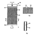
図1,1a,1bは、本発明によりハニカムモノリスとして提供された触媒床構造体を用いた反応器およびその構成部材の部分図を示す。図1は、ハニカムモノリス触媒12の集合体からなる触媒充填体を含む反応器10の縦断面図である。これらの触媒は、図1の断面1a−1aでとられた反応器10の頂部の平面図である図1aに分かり易く示されている。これらの触媒構造体は、市販されているハニカム触媒材料からなっていても、本発明による微細構造形状を持つ他の触媒モジュールからなっていても差し支えない。
【0020】
反応器の動作において、反応器の外囲容器11中に導入される気液供給混合物14は、モノリス触媒12の頂部に供給され、モノリス通路18を通って並流で下方に流れて、触媒積重体の基部で生成混合物16を生成する。図1bは、モノリス触媒12中の通路18の内の1つの拡大図であり、この通路は、供給混合物14を処理するための触媒を有してなる通路壁19を境界としている。使用すべき特定の触媒の選択およびその触媒をハニカムモノリス内に配置する様式は、ここでも、処理すべき物質および用いるべき処理条件に応じて、決まりきった様式で決定できる。重要な特徴は、気液反応体の流れが、固体触媒により触媒作用を受ける別々の反応通路内に主に制限されることである。それゆえ、通路間を横切る流れは、触媒通路に沿った主要な流れに対して取るに足らないすなわち重要ではない。
【0021】
適切なモノリス設計の一例としては、コージエライト、ムライト、アルミナなどの実質的に不活性な多孔質セラミック材料から構成される押出ハニカム体が挙げられ、その内部の通路壁上には、遷移金属または触媒活性金属もしくは周期表(CAS版)のVIB族,VIIB族,VIII族,およびIB族から選択される金属の組合せなどの適切な触媒のコーティングまたは分散体が配置されている。選択された触媒は通路壁上に直接堆積されていても、もしくは多孔質担持金属酸化物ウォッシュコートまたは壁表面に施される他のキャリヤ層上またはその内部に担持されていてもよい。あるいは、触媒は、ハニカムの細孔構造内に担持されていても、またはハニカム壁自体が活性触媒から形成されていてもよい。遷移金属酸化物および他の触媒活性材料から構成されたハニカムがよく知られている。
【0022】
3つの異なる群の重要なパラメータが、本発明による触媒床構造体を含む反応器の効率を決定する。(i)触媒通路内で維持される、特に液体線速度(V1)および気体/液体比(G/L)を含む液体および液体流動条件、並びに(ii)通路開口部の水力直径(lc)、触媒壁の厚さ(lcat)、触媒構造体のセル密度(nc)、すなわち、触媒の単位断面積当たりの通路の数、通路の形状(Φ)、および通路開口部の通路長さに対する比(γ)を含む、触媒床構造体の幾何学的パラメータが最も重要である。選択した触媒の活性および用いる反応条件(温度、圧力)は、反応器の効率を左右する第3群のパラメータであるが、これらは、行われる特定の化学反応に大いに依存するのが明らかである。これとは対照的に、流動条件および触媒床の幾何学的パラメータには、様々な異なる反応タイプに対してより包括的な適用性および重要性があることが分かった。
【0023】
ハニカム触媒に通す三相処理を施せる液体炭化水素供給原料のほとんどについて、ハニカム通路は、一般に、約0.02〜10mmmの範囲の水力直径を与えるようなサイズになっている。水素添加および水素化精製反応は、通路の水力直径が0.1から5mmの狭いサイズ範囲にあるハニカムにおいて実施することができる。これらのサイズ範囲にある通路の開口部は、従来の充填触媒のペレット床における粒子間空隙に寸法で匹敵する。産業的に従来用いられているペレット床における触媒ペレットサイズは、約0.03から約0.25インチ(約0.75から約6.25mm)の範囲にある。通路の寸法が小さすぎる場合、処理プロセス中にその場で生成されるまたは供給流により運び込まれる微粒子により通路が塞がれることがある。通路が大きすぎる場合、触媒床構造体の幾何学的表面積が、効率的な気体/液体/触媒の接触には小さ過ぎるかもしれない。
【0024】
市販のハニカム触媒または触媒担体の通路壁の厚さは、通常、約0.01から5mmの範囲にある。補助的な触媒コーティングを担持する目的および触媒材料から直接形成されたハニカムを製造する目的の両方にとって、0.1から2mmの範囲の壁厚が好ましい。
【0025】
処理に用いるべきハニカムモノリスについて選択されたハニカムのセル密度(通路のアライメント軸に対して垂直にとられたハニカム断面の単位面積当たりの通路の数)は、現在利用できるハニカム支持構造体の範囲内のいずれに含まれていてもよい。10〜3000通路毎平方インチ(cpsi)(約1.5〜480通路毎平方センチメートル)の範囲のセル密度が有用である。約25〜400cpsi(約4〜64通路毎平方センチメートル)の範囲のセル密度が、より広く入手でき、ほとんどのプロセスにとって極めて適している。
【0026】
これらの触媒床構造体における通路の直径に対する長さの比は、一般に、約10よりも大きい。この比が小さ過ぎると、触媒床構造体の効率が、無作為に充填されたペレット床のものに近づき始める。もちろん、どのような特定の反応器の環境にとっての最適比も、使用する特定の触媒モジュール構造体の設計の費用と製造のし易さ、および反応器アセンブリの要件により、並びに触媒床に亘る気体と液体の流れの分布に関する課題により課せられる制約により決まる。
【0027】
これらの反応のためのハニカム触媒を用いた反応器によって、トリックル・ベッド反応器よりも効率的に、利用可能な触媒表面および容積を使用でき、気体と液体の反応体の利用できる触媒の表面へおよびその塊中への物質移動を増加させることができる。トリックル・ベッド水素添加反応器における触媒表面は完全にまたはほぼ完全に湿潤していると一般に認められている。この湿潤挙動により、実際的に関心のある流動条件下、例えば、従来の水素添加プロセスに関して1cm/sの通液線速度で、触媒を十分に使用できるものと考えられた。例えば、"Liquid-Solid Wetting Factor In Trickle-Bed Reactors: Its Determination By A Physical Method" by Pironti et al., in Chemical Engineering Science, 54 (1999) 3793-3800を参照のこと。しかしながら、以下により詳しく説明するように、水素添加および水素化精製プロセスに従来用いられているトリックル・ベッド反応器に触媒を使用することには重大な問題がある。その問題は、本発明によるハニカム触媒を備えた反応器を用いることにより、実質的に克服できる。
【0028】
図2(従来技術)に示すような、一般的なサイズ(例えば、直径1/32インチから1/4インチ(約0.78mmから約6.25mm))の触媒ペレットを用いた充填ペレット床反応器の効率に影響を与える問題の1つは、流れが塞がれるという問題である。図2に示したように、水素ガス流20および液滴22が充填触媒床に進入し、触媒ペレット24の一群を下方に通って移動すると、ペレットと接触する液体が、全ての利用できる触媒ペレットの外面上に広がる。このように広がった液体は、触媒ペレットの中の空隙を満たす傾向にあり、適切なサイズと形状のペレット間空隙26中に毛管力により優先的に捕獲される。
【0029】
どこでこのことが生じようとも、水素ガス流は、拘束された液体によって塞がれていない、触媒床を通る別の道筋を見つけなければならない。したがって、触媒床中の空隙に捕獲された液体供給流の一部は、反応体ガス流にとっては比較的到達できない。これにより、触媒の利用度が事実上減少し、これと同時に、水素が比較的利用されなくなるために淀んだ液体区域に生じ得る、コークス化などの二次反応が生じる可能性が増す。この原因は、触媒ペレットがこれらの反応器中に配置される様式であるので、この根本的な欠点は、充填床反応器に固有のものである。すなわち、反応器への入口で理想的に均一な流動分布が形成された場合でさえも、気体および液体が充填床を通って無作為に流れるので、そのような均一性を維持しようがない。
【0030】
充填床反応器とは対照的に、ハニカムまたは他の触媒構造体を含む反応器の重要な利点は、バルク気体および液体の流れが、充填床反応器における触媒ペレット間の道筋と似た寸法に分割されるけれども、捕獲および滞留に対してより耐性があることである。図3に示したように、これは、触媒の通路壁と接触する液体22は通路の表面上に広がる傾向にあり、気体流れ20が触媒床を通過するのに利用できる自由な通路空間が残されるという事実に起因する。それゆえ、液体の捕獲が起こりそうになく、利用できる触媒の表面に亘り気体と液体のより均一な分布が実現される。これと同時に、表面反応と、壁上の液体膜への気体流により加えられる張力とがさらに、液体交換、すなわち、液体のバルクから触媒表面への物質移動を促進させる。
【0031】
充填床およびハニカム触媒の相対的な性能特徴を、適応できる反応速度方程式を踏まえてさらに分析することができる。したがって、一般形態の水素添加または水素化精製反応については:
【数1】

以下のように書くこともできる:
【数2】
ここで、Rappは、mol/(s・m3)で表した見掛けの反応速度であり;fL/Sは、液状反応体により覆われた触媒の外面の割合であり;fcatは、触媒容積の割合であり;Ageoはm2/m3で表した触媒の幾何学的表面積であり;θcatは、触媒層の有効係数であり;ΦThは、触媒中の反応のThiele数であり;ksは固有反応速度定数であり;CA,Sは、mol/m3で表した触媒の外面での反応Aの濃度であり;CB,avgは、mol/m3で表した触媒内部の反応Bの反応速度平均濃度であり;lcatは、mで表したハニカム通路表面の触媒層の厚さであり;kapp,sは、触媒表面の毎秒の見掛けの速度定数であり;Deffは、触媒中のm2/sで表した反応体Aの有効拡散率であり;αは単位転化係数である。
【0034】
触媒有効係数θcatは、触媒の厚さが減少すると共に増大すると予測されるが、ハニカム触媒においては、触媒の容積の割合fcatは壁厚が減少すると共に減少し、したがって、触媒を薄くすることからは、反応器の容積基準で反応活性の利点は期待できないであろう。もちろん、触媒床の幾何学的表面積は、触媒の粒径または通路の開口部のサイズが減少すると共に増大するであろうし、実際的に実施できれば、小さな触媒サイズが一般に望ましいことが知られている。しかしながら、トリックル・ベッド反応器においては、小さなサイズの触媒の使用は流体力学により制限され、ハニカム触媒においては、通路サイズを減少させると、製造コストが増大し、通路が詰まる可能性も増える。
【0035】
これらの要因にもかかわらず、水素添加反応にハニカム床を使用すると、触媒の幾何学的表面積および物理的容積が充填ペレット床のものよりも大きくなっていない場合でさえも、意外なことに、高い反応速度が生じる。理論により拘束することを意図するものではないが、より速い速度は、現在、(i)任意の所定の瞬間で炭化水素液状反応体Aによる、高い触媒表面被覆率および(ii)任意の所定の瞬間での触媒表面上の反応体AおよびB両方の高い濃度によるものである。
【0036】
液体被覆率の利点に関して、上記方程式(2)から、見掛け反応速度Rappは、液体/触媒接触効率に正比例するのが分かる。また、液体/触媒接触プロセスは明らかに動的で複雑であるが、触媒通路の単純な幾何学形状のために、充填触媒ペレットよりも、液体がより容易に到達できる。
【0037】
反応体濃度の利点は、ハニカム触媒中の気体と液体が比較的小さな反応領域内に 共に閉じこめられるという事実から生じると考えられている。上記方程式(4)は、2つの反応体の内のいずれか一方が利用できない場合、反応速度がゼロになることを示している。ハニカムにおいて、ハニカムの通路壁表面の液体炭化水素膜は、ペレットの隙間に毛管作用により液体が捕獲されることがないので、連続して補充される。さらに、通路を通る適切なレベルの水素流を使用することにより、液体と気体の反応体両方の触媒表面での濃度が最大になるように液体炭化水素膜を壊すのが容易になる。
【0038】
2つの群の水素添加反応、すなわち、オレフィン水素添加およびトルエン飽和が、本発明の実施により利益をもたらすことのできる反応タイプの代表例である。これらの反応の特定の例は以下の通りである:
【数3】
オレフィン水素添加は反応速度的に速い反応であり、反応効率は主に、不飽和炭化水素液体と触媒の外面との間の接触の性質による。これらの反応は、芳香族ではない分子構造における不飽和化学結合の飽和を含む他の水素添加反応の代表例である。他方で、トルエン飽和は、オレフィン飽和よりも反応速度的にずっと遅く、芳香族分子構造における不飽和化学結合の水素添加の代表例である。さらに、オレフィン飽和よりも芳香族飽和のほうがより多くの水素分子が必要である。同様な反応としては、モノ芳香族とポリ芳香族の化合物、またはチオフェン、ベンゾチオフェン、およびジベンゾチオフェンを含む芳香族硫黄化合物の飽和が挙げられる。
【0040】
以下の具体例は、上述したタイプの水素添加および水素化精製反応に関する本発明の利点の内のいくつかを示す。
【0041】
具体例I(従来技術) オレフィン水素添加 − 充填床(トリックル)反応器
1/8インチ(約3.1mm)のNi/アルミナ触媒ビーズ10ccを、1インチ(約25mm)の直径の管状反応器中にSiC粉末希釈剤と共に充填した。SiC希釈剤は、60メッシュのSiC粉末40ccからなるものであった。追加の量のSiC粉末を用いて、反応器内に触媒を支持するための端部栓を形成した。
【0042】
次いで、このように充填した触媒を、ゲージ圧で220psi(約1.54MPa)の反応器圧および400℃の反応器温度で10時間に亘り反応器に水素を流動させ、次いで、冷却することにより、前還元した。水素による前処理後、5%の1−オクテン、5%のスチレン、および90%のトルエンからなる液状反応体を、反応器への供給管内で流動している水素ガス流と混合し、この混合流を所定の反応温度まで予熱し、次いで、加熱された混合流を気体/液体供給流として反応器の頂部に導入した。
【0043】
反応器中にこのように導入した供給流を、並流モードで下向きに反応器に通して流動させ、触媒床を通過させ、ここで、スチレンおよび1−オクテンに水素添加して、それぞれ、エチルベンゼンおよびn−オクタンを含む生成物流を生成した。次いで、この生成物流を冷却し、気体と液体の生成物に分離した。液体生成物を分析して、反応器の転化効率を求めた。
【0044】
様々な反応条件下でこの反応器により得られた1−オクテンおよびスチレンの各々に関するオレフィン転化率が、以下の表1に報告されている。報告された各反応条件に関して、psigで表された運転中に維持した反応器圧、H2/油比(炭化水素液体のリットル[L]に対する標準温度および圧力での水素ガスのリットル[NL])、反応器を通る混合供給流の液空間速度(LHSV)、触媒床の底部で測定した反応器温度、スチレンと1−オクテンのそれぞれの水素添加生成物への転化率パーセント、および1−オクテン水素添加転化率および液空間速度から計算した触媒の計算上の1−オクテン転化活性が、表1に含まれている。
【表1】
表1に報告されている計算上の1−オクテン転化効率により、共通した設計の反応器における異なる触媒充填および触媒形状の水素添加性能を比較するための都合のよい基準が得られる。表1のデータが示すように、この充填床反応器設計における転化効率は、反応器圧および供給H2/油容積比が同じに維持されれば、LHSVと共にいくぶん増大し、温度が減少するといくぶん減少するようである。また、一定のLHSVおよびほぼ一定の温度の条件下では、転化効率は、圧力および供給H2/油容積比と共に増大する。
【0046】
気体/液体水素添加処理に関するペレット化された水素添加触媒の効率に関するさらに別の情報が、触媒ペレットの充填が、以下の方法にしたがって、流れの通路化および反応器の効率を制限する他の影響を減少させるように理想化されている反応器の試験からのデータにより得られる。
【0047】
具体例 II オレフィン水素添加 − 理想的な充填床
具体例Iに上記のごとく用いたものと同じ組成および形状のNi/アルミナ触媒ビーズを、直径1/4インチ(約6.25mm)、長さ約12インチ(約300mm)のステンレス鋼製反応管中に個別に充填した。この管の内径(約3mm)は、ペレットの直径よりもわずかに大きいだけであり、単独ペレットのカラムに、管内で供給流が流れることのできる空隙が形成される。この構成に関する触媒充填容積および空隙率は、それぞれ、約2.15ccおよび0.33であった。
【0048】
触媒ペレットは、ゲージ圧で220psi(約1.54MPa)の反応器圧および400℃の反応器温度で供給した水素ガスを10時間に亘り流すことにより、その場で前還元させた。次いで、水素ガスおよび液体炭化水素反応体のブレンドからなる混合気体/液体供給流を、供給管を通して反応器の頂部に導入し、下向きに触媒表面を流した。この反応体ブレンドは、0.5重量%の1−オクテン、0.5重量%のスチレン、および99重量%のトルエンから構成された。水素と液体とを供給管内で混合し、触媒と接触させる前に適切な反応温度まで予熱した。この理想的に充填された反応器中の気体/気体流は、ほぼ触媒ビーズサイズの規模に制限されており、従来のトリックル・ベッド反応器において反応体がしたがう無作為で曲がりくねった流路と、比較的規則的なものとして比較される。
【0049】
この反応器において様々な条件下で観察されたオレフィン転化率が以下の表2に報告されている。実施した各運転に関して、℃で表した触媒床の頂部と底部で測定した温度、cm/sで表した反応器を通る液状反応体流の計算した平均線速度、H2/油比(炭化水素液体のリットル[L]に対する標準温度および圧力での水素ガスのリットル[NL])、反応器を通る混合供給流の液空間速度(LHSV)、スチレンと1−オクテンのそれぞれ水素添加されたエチルベンゼン(EB)およびn−オクタン生成物への転化率パーセント、および1−オクテン転化率および反応器を通る液空間速度(LHSV)から計算した触媒の測定した1−オクテン転化活性が、表2に含まれている。全ての反応は、ゲージ圧で220psi(約1.54MPa)の反応器圧で行った。
【表2】
表2のデータが示すように、具体例IIの理想的に充填された反応器設計に関する転化率および活性の結果は、同様の反応条件下と同様の流速で比較した場合、具体例Iの従来のトリックル・ベッド反応器設計に関する結果よりも一般に一層好ましい。これらの結果は、気体/液体/触媒表面の接触が効果的でないことが、従来のトリックル・ベッド反応器の効率を制限する重大な要因であることを示唆している。
【0051】
また、表2のデータが示すように、理想的に充填された触媒の水素添加活性は、液体速度と、反応器を通る液体流速に対する水素流速とに直接的に依存する。例えば、液体の供給量が、7倍、すなわち、0.12cm/sから0.83cm/sまで、反応器を通る液体速度を上昇させるように増大された場合、1−オクテンの転化率はわずかに減少するが、触媒の見掛けの1−オクテン転化活性は、ほぼ4倍、すなわち、0.0026から0.115v/v/sまで、増大する。
【0052】
以下の説明のための具体例に示したように、充填ペレット床に取って代わるハニカムを使用することにより、水素添加および水素化精製反応のための別の反応器の性能の利点が得られる。
【0053】
具体例 III オレフィン水素添加 − 触媒被覆壁を持つ触媒構造体
直径が1cm、ハニカムの通路が向いている方向で長さが30cmである、正方形通路が形成されたハニカム形状を持つモノリス構造触媒を、アルミナのウォッシュコートが施されたコージエライトハニカム基体をNi硝酸塩溶液に含浸することにより調製した。ウォッシュコートが施されたモノリスは、通路の公称直径が1mm、通路の壁厚が約0.2mm、ハニカム中の通路が向いている方向を横切る平面で測定したセル密度が400cpsi(約64通路毎平方センチメートル)であった。ウォッシュコートをニッケルで含浸した後のNi/アルミナ触媒層の厚さは約0.05mmであった。
【0054】
触媒性能を供給流分布効果とは区別するために、触媒モジュールの1つの通路を、ハニカムの底部と頂部の他の通路の開口部を液体不浸透性セメントで塞ぐことにより、試験目的のために孤立させた。次いで、外径1/8インチ(約3.125mm)のステンレス鋼製供給管を、孤立させた通路の頂部に前記セメントで取り付けた。
【0055】
このように調製した触媒モジュールを、SiC粉末の素材により取り囲んだ、直径2cmの管状反応器内に配置した。次いで、この触媒モノリスを、ゲージ圧で220psi(約1.54MPa)および400℃で10時間に亘り反応器に水素ガスを流すことにより、その場で前還元させた。
【0056】
このように触媒を調製した後、水素ガスおよびブレンドした炭化水素液状反応体からなる気体/液体供給流を、ステンレス鋼製供給管に通して触媒通路中に供給し、下向きに触媒モノリスに通して流した。気体と液体の混合物は、触媒に接触させる前に所定の反応温度まで予熱した。触媒の処理後、反応器からの流出物を室温より低く冷却し、気体を除いて、液体生成物に分離した。次いで、液体生成物を分析して、スチレンのエチルベンゼンへの水素添加度および1−オクテンのn−オクタンへの水素添加度を求めた。
【0057】
様々な異なる反応条件を用いたいくつかの転化運転をこの反応器を用いて評価し、これらの運転には2つの異なる液体供給流を用いた。供給流Iは、5重量%の1−オクテン、5重量%のスチレン、および90重量%のトルエンからなり、供給流IIは、0.5重量%のスチレン、0.5重量%の1−オクテン、および99重量%のトルエンからなるものであった。反応器中への供給流の流速を増加させることにより、ある範囲の液体線速度および液空間速度に亘る転化データを作成できる。
【0058】
この試験の一般結果が以下の表3に報告されている。実施した各運転に関して、℃で表した触媒床の頂部と底部で測定した温度、cm/sで表した反応器を通る液状反応体流の計算した平均線速度、psigで表した運転を行った反応器圧、H2/油比(炭化水素液体のリットル[L]に対する標準温度および圧力での水素ガスのリットル[NL])、反応器を通る混合供給流の液空間速度(LHSV)、スチレンと1−オクテンのそれぞれ水素添加されたエチルベンゼン(EB)およびn−オクタン生成物への転化率パーセント、および1−オクテン転化率および反応器を通る供給流の液空間速度(LHSV)から計算した触媒の測定した1−オクテン転化活性が、表3に含まれている。
【表3】
この試験の過程で観察した水素添加転化率および触媒活性は、予期せぬほど高い。例えば、反応器が比較的短い(30cm)にもかかわらず、いずれの供給流についても、0.83cm/sの液体線流速で、99%を超えるスチレン転化率が得られた。さらに、転化の程度は、反応器を通るLHSVが増加するにつれ減少するが、表3に列記した試験条件の全てについて、これらの水素添加に関して有効なワンパス転化率が得られた。それゆえ、多くの化学プロセスを工業規模で実施するために、モノリス触媒により、再利用コストが高くつくであろう微分反応器操作とは反対に、一体型すなわちワンパス水素添加反応器の操作が可能となる。
【0060】
上記のごとく試験したペレット化触媒および触媒構造体の根本的な水素添加活性の差は、さらに一層意外である。表1〜3のデータは、具体例IIIの触媒構造体が、具体例IおよびIIのペレット床触媒について計算した1−オクテン水素添加活性よりも一桁から二桁大きい対応する活性を実証していることを示している。例えば、20NL/Lの供給H2/油比および約61℃の供給温度を用いて、約0.83cm/sの液体線速度レベルでは、ゲージ圧で220psi(約1.54MPa)の操作圧力で理想的な充填床反応器のオレフィン水素添加活性は、約0.0115s-1である。同様な条件下で、触媒反応器構造体は、0.088s-1の水素添加活性レベルで作動する。この触媒構造体についての触媒活性がこのように約7.6倍も増加したことは、ペレット化触媒よりわずかに優れた幾何学的表面積の利点(モノリスの2300m2/m3対ペレット床の1400m2/m3)からは予測できなかった。これらのデータは、充填床反応器中のの活性触媒表面が十分に利用されていないという結論を裏付けている。
【0061】
具体例 IV オレフィン水素添加 − 嵩のある触媒壁を持つ触媒構造体
直径が1cm、ハニカム通路の方向の長さが30cmの、円筒型ハニカム形状を持つ触媒構造体の支持モノリスを試験のために調製した。2つのモノリス形状を選択した。両方とも、実質的に完全に多孔質ガンマアルミナからなるものであった。第1の形状は、400cpsi(約64通路毎平方センチメートル)のセル密度で0.18mmの厚さの通路壁を境とする直径1mmの正方形通路を備えるものであった。第2の形状は同じ直径の正方形通路を備えるが、通路壁は厚さが0.71mmであり、セル密度は200cpsi(約32通路毎平方センチメートル)であった。
【0062】
これらのハニカム支持体の多孔質壁には、2Mの硝酸ニッケル水溶液中にハニカムを浸漬し、この溶液からハニカムを取り出し、ハニカム通路を圧縮空気で洗浄し、約16時間に亘り100℃のオーブン中で含浸ハニカムを乾燥させ、最後に、2時間に亘り400℃の炉内の空気中で乾燥したハニカムをか焼して、その中のニッケル塩を酸化ニッケルに転化することにより、活性な水素添加触媒を充填した。このようにして提供した完全に触媒化された400cpsi(約64通路毎平方センチメートル)のハニカムは、ハニカムの壁構造全体に亘り分布する約9.3重量%のNiO添加量を持ち、多孔質壁は214m2/gのBET表面積を有していた。200cpsi(約32通路毎平方センチメートル)のハニカムは9.0重量%の触媒添加量を持ち、その壁は190m2/gのBET表面積を有していた。
【0063】
これらのNi/アルミナ触媒を、具体例IIIに述べた方法を用いて水素添加活性について試験した。これらの触媒を評価するのに用いた液体供給流は、0.5重量%のスチレン、0.5重量%の1−オクテン、および99重量%のトルエンからなるものであった。試験の結果が以下の表4に示されている。実施した各水素添加運転に関して、℃で表した触媒床の頂部と底部で測定した温度、cm/sで表した反応器を通る液状反応体流の計算した平均線速度VL、psigで表した運転を行った反応器圧、H2/油比(炭化水素液体のリットル[L]に対する標準温度および圧力での水素ガスのリットル[NL])、スチレンと1−オクテンのそれぞれ水素添加されたエチルベンゼン(EB)およびn−オクタン生成物への転化率パーセント、および転化率および反応器を通る供給流の液空間速度(LHSV)から計算した触媒の測定した1−オクテン転化活性が、表4に含まれている。
【表4】
表4のデータを検討することにより分かるように、これらの触媒構造体について、0.83から15.0cm/sの全液体線速度範囲に亘り、60%以上のワンパスオレフィン転化率が得られた。これらのデータは、モノリスの壁構造中に存在する触媒の嵩を増すほど、触媒活性すなわち添加効率に関する利点が少なくなることも示している。したがって、液状反応体と触媒表面との接触効率は、これらの反応器における水素添加性能に影響を与える重要な要因であるようである。
【0065】
具体例V オレフィン水素添加 − 嵩のある触媒壁を持つ触媒構造体
具体例IVにおけるように、正方形通路を持つ円柱型ガンマアルミナハニカムモノリス基体をNi硝酸塩に含浸することにより、触媒構造体を調製した。選択した基体は、直径が1cm、円柱の長さが30cm、セル密度が100cpsi(約16通路毎平方センチメートル)、通路の壁厚が0.64mm、通路の直径が2mmであった。触媒の含浸後、触媒化モノリスは、9.0重量%のNiOの触媒添加量および187m2/gのBET表面積を有した。この触媒の形状は、その幾何学的表面積(GSA)が上述した具体例IIにおいて評価した理想的に充填されたペレット床触媒のものと非常に似ている。
【0066】
具体例IIに記載した方法により、0.5重量%のスチレン、0.5重量%の1−オクテン、および99重量%のトルエンを含有する液体供給流を用いて水素添加活性について試験した場合、以下の表5に述べた性能データが作成された。実施した各水素添加運転に関して、℃で表した触媒床の頂部と底部で測定した温度、cm/sで表した反応器を通る液状反応体流の計算した平均線速度VL、psigで表した運転を行った反応器圧、H2/油比(炭化水素液体のリットル[L]に対する標準温度および圧力での水素ガスのリットル[NL])、スチレンと1−オクテンのそれぞれ水素添加されたエチルベンゼン(EB)およびn−オクタン生成物への転化率パーセント、および転化率および反応器を通る供給流の液空間速度(LHSV)から計算した触媒の測定した1−オクテン転化活性が、表5に含まれている。
【表5】
表5データは、この触媒において、0.21cm/sほど低い通液線速度で、スチレンおよび1−オクテンの両方について、90%を超えたワンパス転化率を達成できることを示している。観察された他の効果には、0.83cm/sの液体線速度で供給流のH2/油比が増加するにつれ、オレフィン転化率がやや減少するが、4.17cm/sでのより高いH2/油比ではオレフィン転化率は増加することがある。
【0068】
この触媒構造体の性能は、同様の液体線速度(それぞれ、0.42cm/sおよび0.47cm/s)および同様のH2/油比(50NL/L)で比較した場合、具体例IIの理想化された充填ペレット床の性能よりも優れた明らかな利点を示す。これらの流速は、市販のペレット床反応器において用いられる流動と異なっていないが、それでも、この具体例Vの触媒構造体の水素添加活性(0.041 1/s)は、充填ペレット床反応器に見られる0.0091 1/sの活性レベルの4倍以上大きい。ここでも、この活性の利点は、触媒構造体反応器において維持される基体/液体触媒接触がより効率的であることに起因し得る。
【0069】
具体例 VI 芳香族の飽和 − 嵩のある触媒壁を持つ触媒構造体
通路壁の厚さが1.0mmに増大し、通路形状が円形の通路断面に変化したことを除いて、具体例Vの基体と同じ形状を持つガンマアルミナハニカム基体を、具体例IIIの方法にしたがって酸化ニッケル触媒に含浸した。このように提供した触媒モノリスは、7.35重量%のNiO触媒添加量および175m2/gのBET表面積を有した。
【0070】
この触媒は、具体例IIIの方法により作製し、水素添加活性について試験したが、この場合、試験した活性は、芳香族化合物のトルエンの環状炭化水素のメチルシクロヘキサンへの転化率についてであった。活性試験には、様々な異なる反応条件下で多数の炭化水素混合物の水素添加が含まれ、各々の炭化水素混合物は、選択した比率のトルエン反応体を中にブレンドしたメチルシクロヘキサン基質を有してなるものであった。これらのブレンドを混合し、水素ガス供給流と共に予熱し、気体/液体混合物を、鋼製供給管を通して触媒モノリスに供給した。
【0071】
これらの試験結果が以下の表6に報告されている。実施した各水素添加運転に関して、℃で表した触媒床の頂部と底部で測定した温度、cm/sで表した反応器を通る液状反応体流の計算した平均線速度VL、psigで表した運転を行った反応器圧、H2/油比(炭化水素液体のリットル[L]に対する標準温度および圧力での水素ガスのリットル[NL])、トルエン−メチルシクロヘキサン供給流の重量パーセントとしての供給流トルエン濃度、反応器を一回通ったときのトルエンのメチルシクロヘキサンへの転化率パーセント、および一次反応速度論の前提に基づいた、トルエン転化率パーセントおよび反応器を通る供給流の液空間速度(LHSV)から計算した触媒の見掛けのトルエン転化活性が、表6に含まれている。
【表6】
表6のデータが示すように、一定の反応条件下では、トルエンの転化率の程度が、供給流中のトルエンの含有量と共に減少し、VLが上昇するにつれ(すなわち、触媒と供給量の接触時間が減少する)減少する。それにもかかわらず、1.59cm/sのVLで、試験した全てのトルエン濃度レベルにおいて73%を超えるメチルシクロヘキサンへの転化率が達成された。転化率におけるある程度の変動は、圧力変化およびH2/油比における変化からのものであると観察された。転化率は、ほとんどの濃度で、試験範囲の高い温度や低い温度よりむしろ、中間で最大となるようであった。一般に、トルエン水素添加活性は、反応タイプの根本的な差のために、1−オクテン水素添加活性よりもずっと低いことが分かっているが、適切な温度と流速で高いワンパス転化率を達成する触媒の能力は明白である。
【0073】
この具体例のNiO/アルミナ触媒構造体(ハニカムモノリス)の水素添加活性と、トリックル・ベッド反応器中に充填された粒子形態の同じ触媒との間で比較した。この比較のために、この具体例のNiO/アルミナハニカムを粉砕し、篩にかけて、80〜200メッシュの触媒粒子を作製し、次いで、この粒子を1時間に亘り400℃のオーブン中でか焼して、残留炭化水素を除去した。次いで、か焼した触媒1.5ccを、具体例Iに記載したようにSiC粉末希釈物およびSiC端部栓を用いて、内径2cmの管状反応器中に充填した。
【0074】
この反応器の水素添加活性を、液相がメチルシクロヘキサン基質中に4.2重量%のトルエンを有してなる気体/液体供給流を用いて試験した。この試験は、95h-1の液空間速度、50NL/Lの供給流H2/油比、およびゲージ圧で220psi(約1.54MPa)の反応器圧で、ある温度範囲に亘り行った。次いで、この試験結果を同じ反応器の動作条件下でこの具体例の触媒構造体を用いて得られた結果と比較した。
【0075】
この比較結果が図4に示されている。このグラフは、ある作動温度範囲に亘る反応器の作動温度に対する転化効率のプロットである。転化効率は、供給流中のトルエンのメチルシクロヘキサンへの転化率パーセントでプロットされている。図4の検討から分かるように、触媒構造体の転化活性は、180年未満の全ての反応器の温度で粉砕触媒の活性を著しく超えている。トリックル・ベッド反応器の活性が匹敵するようになるのは、この地点を超えた温度でのみである。
【0076】
具体例 VII 芳香族飽和 − 嵩のある触媒壁を持つ触媒構造体(200cpsi)
具体例VIのモジュールに似ているが、200cpsi(約32通路毎平方センチメートル)のセル密度、0.71mmの通路の壁厚および1mmの通路の直径を持つ触媒構造体モジュールを試験のために調製した。具体例IVの触媒調製方法にしたがった。この触媒モノリスは、9.3重量%のNiOの触媒添加量および214m2/gのBET表面積を有するものであった。
【0077】
この触媒構造体を、具体例IIIに記載した試験方法およびメチルシクロヘキサン基質中に4.5重量%のトルエンを有してなるトルエン−メチルシクロヘキサン液体供給流を用いて、水素添加活性について試験した。この試験により得られた結果が以下の表7に報告されている。実施した各水素添加運転に関して、℃で表した触媒床の頂部と底部で測定した温度、cm/sで表した反応器を通る液状反応体流の計算した平均線速度VL、psigで表した運転を行った反応器圧、H2/油比(炭化水素液体のリットル[L]に対する標準温度および圧力での水素ガスのリットル[NL])、反応器を一回通ったときのトルエンのメチルシクロヘキサンへの転化率パーセント、およびトルエン転化率パーセントおよび反応器を通る供給流の液空間速度(LHSV)から計算した触媒の見掛けのトルエン転化活性が、表7に含まれている。
【表7】
この具体例VIIの触媒および具体例VIの触媒により示された活性の比較により、反応器の動作条件に依存して、より高いセル密度およびより小さな通路サイズを持つ触媒モノリスを使用することにより、約2から約10倍の水素添加活性の改善が実現できることを示唆している。
【0079】
もちろん、上述した記載および具体例は、単に本発明の説明目的であり、これまで記載した組成、プロセスおよび装置に変更を行うことは、添付した特許請求の範囲内で当業者が実施できるであろう。
【図面の簡単な説明】
【0080】
【図1】本発明に使用するのに適した反応器設計および触媒形状を示す
【図2】従来技術による供給流の流れモードを示す
【図3】本発明による触媒構造体を通る供給流の流れモードを示す
【図4】本発明による触媒構造体反応器および充填床反応器の効率を比較するグラフ
【符号の説明】
【0081】
10 反応器
12 ハニカムモノリス触媒
14 気液供給混合物
16 生成混合物
18 モノリス通路
20 水素ガス流
22 液滴
26 触媒ペレット【Technical field】
[0001]
The present invention relates to the use of solid catalyst bed structures or monolithic catalysts for efficient treatment of gas-liquid feed streams, and more particularly for performing hydrorefining and hydrogenation reactions at high speed and high conversion efficiency. It concerns the treatment of such feed streams.
[Background Art]
[0002]
Fixed bed reactors packed with various forms of catalyst pellets, such as beads, cylinders, wheels, etc., have been widely used in the refining industry to perform chemical treatments and hydrotreating and hydrotreating processes. Many of these processes are performed as a three-phase (gas-liquid-solid) process in which a gas-liquid feed stream is reacted on a solid catalyst surface. Hydrorefining is an important refining process for producing clean (low sulfur) fuels from petrified feedstocks, while hydrogenation is widely used in the production of various chemicals.
[0003]
Industrial pellet bed reactors for performing such processes, commonly referred to as "trickle bed" reactors, are generally in gas-liquid down-flow co-current mode, i.e., gaseous reactants and liquid Both reactants operate in a mode that flows through the catalyst bed in the same direction (down). The linear velocity in such a reactor, calculated from the length of the catalyst bed and the average transit time of the liquid through the catalyst bed, is in the range of about 0.01 to 2 cm / s. Trickle bed reactors have been successfully used in the industry for almost half a century and represent a mature chemical processing technology. Refining this technique involves optimizing the catalyst size, shape, and packing method, for example, adjusting the operating regime by using somewhat faster liquid flow rates. However, such improvements are additive in nature and do not significantly increase the efficiency of these processes.
[0004]
Over the past two decades, a great deal of research effort has been devoted to the development of catalyst structures such as monolithic catalysts and honeycomb catalysts. Honeycomb monoliths are widely used to carry catalysts for the gas phase treatment of combustion engine exhaust gases in catalytic converters of vehicles. On the other hand, the use of monoliths to perform three-phase reactions involving the treatment of gas-liquid feed streams is very limited. These reaction systems are very different gas phase reaction systems.
[0005]
Of course, the advantages of low pressure drop of honeycomb monolith catalysts are well recognized and various studies of the behavior of such catalysts have been reported in the literature. However, low pressure drop is just one feature affecting the catalytic performance in these structures, and considerable attention has been given to attempts to understand other reactive performance factors operating in monolithic catalyst beds supporting gas-liquid catalysis. Have been. Indeed, from a reactor engineering point of view, a three-phase catalytic reaction process is much more complex than a gas-phase catalytic reaction, such as occurs in a monolithic catalyst used in a catalytic converter of a vehicle.
[0006]
In
[0007]
Hatziantonlou et al. Compared the hydrogenation of nitro compounds on a Pd / monolith catalyst surface with the same hydrogenation in a slurry reactor, but on a weight basis per catalyst weight basis, Reported that the reaction rate was lower (see Non-Patent Document 3). In Non-Patent Document 4, Smith et al. Tested the hydrogenation reaction of olefins on a Pd / monolith catalyst surface and found that the reaction rate constant was significantly dependent on the linear liquid velocity through the catalyst. .
[0008]
The lack of attention of each of these studies indicates that such catalyst bed structures, when used in the same manner as current industrial catalysts, have better conversion efficiencies than conventional catalyst beds. The question is whether there is an advantage. Therefore, an important question is whether a honeycomb monolith or other catalyst bed structure could indeed be a useful alternative to the industrial catalyst beds currently used in trickle beds or other conventional gas-liquid reactors. Remains. The problem of practical utility is that much of the conversion data reported in the literature is produced on a laboratory scale in small "differential" reactors, which often result in low one-pass conversions of less than 50%. Very few were answered because only rates were available. For economic reasons, large industrial reactors are "integral" reactors, ie, reactors designed to achieve one-pass conversions of more than 50%, often close to 100%. Often operated as a vessel. Unfortunately, due to the complexity of the associated reaction coupling and mass transfer interactions, laboratory findings based on differential reactor data cannot be extrapolated to the performance of the integrated reactor.
[0009]
Another uncertainty relates to the fact that previously recorded laboratory results are often predicted based on the operation of the monolith reactor in a so-called Taylor flow configuration. Taylor flow refers to a flow mode characterized by alternating liquid slag and bubble motion of approximately the same size through the passage of a honeycomb catalyst. Maintaining a Taylor flow generally requires operating the reactor at a relatively high liquid linear velocity (eg, 30 cm / s) and a relatively low gas-liquid ratio (eg, 0.5 V / V). Controlling the feed stream to meet these requirements would not be feasible in plants designed to carry out hydrorefining and hydroconversion processes on an industrial scale.
[Non-patent document 1]
"Catalitic Wet Oxidation Of Acetic Acid Using Platium On Alumina Monolith Catalyst", Catalysis Today, 40 (1998) 59-71,
[Non-patent document 2]
"Competitive Hydrodesulfurization And Hydrogenation In A Monolithic Reactor", AIChE Journal, Vol. 36, No. 5, 746-752 (1990)
[Non-Patent Document 3]
"Mass Transfer And Selectivity In Liquid-Phase Hydrogenation Of Nitro-Compounds In A Monolithic Catalyst Reactor With Segmented Gas-Liquid Flow" Ind.Eng.Chem.Process Des.Dev., 25 (1986) 964-970
[Non-patent document 4]
"Selective Three-Phase Hydrogenation Of Unsaturated Hydrocarbons In A Monolithic reactor" Chemial Engineering Science, Vol.51, No.11, 3019-3025 (1996)
DISCLOSURE OF THE INVENTION
[Problems to be solved by the invention]
[0010]
Therefore, catalyst structures such as honeycomb monoliths can provide significant advantages over conventional catalyst beds in industrial reactors, and if so, for what reactions and under what reaction conditions. It is necessary to determine whether such advantages can be secured.
[Means for Solving the Problems]
[0011]
The present invention relates to a reaction containing a "microstructure" catalyst bed, which can perform three-phase chemical reactions such as hydrogenation and hydrorefining on a one-pass or integrated reactor system with practically useful conversion and high efficiency. Provided is a catalyst conversion method useful for a vessel. “Microstructure” catalyst bed means a catalyst bed that is divided into a number of small catalytic reaction passages having a hydraulic diameter of about 0.1 to 10 mm, which are embodied by honeycomb catalysts of appropriate passage size. You. In a catalyst bed of this construction, the bulk gas stream and the liquid reactant stream are laminarized or split into separate small reactant streams, each of which undergoes a catalytic reaction in a separate passage.
[0012]
The reactors used in these processes generally use a high gas-liquid ratio, and the feed stream of the gas-liquid process is a stream with a high gas-liquid (G: L) ratio. That is, these processes are performed using relatively fast gas flows and relatively low liquid linear velocities to convey the gas-liquid feed stream through the honeycomb catalyst.
[0013]
The invention more particularly comprises an improved method for performing a gas-liquid reaction in the presence of a solid catalyst. According to this method, a gas-liquid feed stream containing a gaseous reactant and a liquid reactant is first conveyed through a monolithic structured catalyst bed. The catalyst has a conventional passage structure, i.e. has a plurality of parallel open-ended passages from the first or inlet face of the body to the second or outlet face, through which the fluid to be treated can freely pass. Provided as a honeycomb or honeycomb assembly with a honeycomb body. Each passage is formed by, or bounded by, the passage wall. These passage walls are preferably provided in the form of thin crossed webs of solid material, on or in which a solid catalyst for treating a liquid stream is provided.
[0014]
When performing the method of the present invention, the liquid making up the gas-liquid supply flow is conveyed through the honeycomb passage at a controlled flow rate limitation. Effective treatment requires that the flow rate of the liquid be adjusted so that the liquid flow velocity through the catalyst is in the range of about 0.1 to 10 cm / s. The flow velocity through the honeycomb catalyst bed is conventionally defined as the quotient of the length of the catalyst bed divided by the average time required for a small segment of the feed liquid to pass through the catalyst bed.
[0015]
While the liquid passes through the honeycomb catalyst bed, the gas components of the feed stream are conveyed to the catalyst bed in an amount that maintains a high gas: liquid (G: L) volume ratio in the passages of the honeycomb. The gas has a gas: liquid ratio in the range of about 1 to 4000 standard (Normal) liters (NL) of gas per liter (L) of liquid present, ie, 1: 1 to 4000: 1 NL / L. It is common to provide a ratio sufficient to maintain the G: L ratio of L. For the purposes of this specification, a gas standard or normal liter is the volume of gas occupying one liter at a standard temperature of 20 ° C. and a standard pressure of one atmosphere.
[0016]
The process conditions described above are useful for performing various three-phase reactions on the surface of a monolith honeycomb catalyst bed, but are particularly well suited for performing a hydrogenation or hydrorefining reaction using a hydrocarbon feed. By this means, various unsaturated or substituted hydrocarbon compounds can be treated efficiently. Unsaturated hydrocarbons that can be processed include straight-chain or branched alkenes or alkynes, as well as aromatic hydrocarbons and hydrocarbons containing unsaturated hydrocarbon functionality. Substituted hydrocarbons include those having a sulfur or nitrogen containing functional group.
[0017]
It is a particular advantage of the method of the present invention that no difficult measures are required to maintain Taylor flow conditions in the honeycomb passage. Indeed, if the process of the present invention is carried out at liquid flow rates and G: L ratios within the ranges specified herein, the theoretical values for these hydrocarbon reactants, whether or not Taylor flow is maintained, One-pass conversions above 50% of the conversion limit, more typically above 80%, can be easily achieved. Therefore, these methods are suitable for use in a single pass or integrated reactor system without the need for high recycling rates or auxiliary processing equipment.
BEST MODE FOR CARRYING OUT THE INVENTION
[0018]
The particular reactor design that should be selected to perform the method of the present invention is not critical, but will depend primarily on the chemistry of the particular reaction to be performed and the environment in which the reaction is to be performed. In each case, the details of the reactor design will depend on the specific reactions to be carried out, the design of the physical plant, and the constraints of the input and output of the feed streams and products that the reactor needs to operate on to be routine to those of ordinary skill in the art. It can be easily selected by work.
[0019]
1, 1a and 1b show a partial view of a reactor using a catalyst bed structure provided as a honeycomb monolith according to the present invention, and components thereof. FIG. 1 is a vertical cross-sectional view of a
[0020]
In operation of the reactor, the gas-
[0021]
One example of a suitable monolith design includes an extruded honeycomb body composed of a substantially inert porous ceramic material such as cordierite, mullite, alumina, etc., on which the transition metal or catalyst A coating or dispersion of a suitable catalyst, such as an active metal or a combination of metals selected from Groups VIB, VIIB, VIII, and IB of the Periodic Table (CAS version) is disposed. The selected catalyst may be deposited directly on the passage walls, or may be supported on or within a porous supported metal oxide washcoat or other carrier layer applied to the wall surface. Alternatively, the catalyst may be supported within the pore structure of the honeycomb, or the honeycomb walls themselves may be formed from an active catalyst. Honeycombs composed of transition metal oxides and other catalytically active materials are well known.
[0022]
Three different groups of important parameters determine the efficiency of a reactor containing the catalyst bed structure according to the invention. (i) the liquid linear velocity (V1) And liquid / liquid flow conditions, including the gas / liquid ratio (G / L), and (ii) the hydraulic diameter (lc), Thickness of catalyst wall (lcat), Cell density of catalyst structure (nc), That is, the geometric parameters of the catalyst bed structure, including the number of passages per unit cross-sectional area of the catalyst, the shape of the passages (Φ), and the ratio of the passage openings to the passage length (γ) are most important. It is. The activity of the selected catalyst and the reaction conditions used (temperature, pressure) are a third group of parameters that affect the efficiency of the reactor, but these obviously are highly dependent on the particular chemical reaction to be performed. . In contrast, flow conditions and catalyst bed geometric parameters have been found to have more comprehensive applicability and significance for a variety of different reaction types.
[0023]
For most liquid hydrocarbon feeds that can be subjected to three-phase processing through a honeycomb catalyst, the honeycomb passages are generally sized to provide a hydraulic diameter in the range of about 0.02 to 10 mm. Hydrogenation and hydrorefining reactions can be carried out on honeycombs with passage hydraulic diameters in a narrow size range of 0.1 to 5 mm. Passage openings in these size ranges are comparable in size to the interparticle voids in conventional packed catalyst pellet beds. Catalyst pellet sizes in pellet beds conventionally used in the industry range from about 0.03 to about 0.25 inches (about 0.75 to about 6.25 mm). If the size of the passage is too small, the passage may be blocked by particulates generated in situ or carried by the feed stream during the treatment process. If the passages are too large, the geometric surface area of the catalyst bed structure may be too small for efficient gas / liquid / catalyst contact.
[0024]
The thickness of the passage walls of commercially available honeycomb catalysts or catalyst supports is usually in the range of about 0.01 to 5 mm. Wall thicknesses in the range of 0.1 to 2 mm are preferred, both for the purpose of supporting the auxiliary catalyst coating and for producing honeycombs formed directly from the catalyst material.
[0025]
The honeycomb cell density (the number of passages per unit area of the honeycomb section taken perpendicular to the passage alignment axis) selected for the honeycomb monolith to be used in the process is within the range of currently available honeycomb support structures. May be included. Cell densities ranging from 10 to 3000 passages per square inch (cpsi) (about 1.5 to 480 passages per square centimeter) are useful. Cell densities in the range of about 25-400 cpsi (about 4-64 passages per square centimeter) are more widely available and are very suitable for most processes.
[0026]
The ratio of length to diameter of the passages in these catalyst bed structures is generally greater than about 10. If this ratio is too low, the efficiency of the catalyst bed structure will begin to approach that of a randomly packed pellet bed. Of course, the optimal ratio for any particular reactor environment will depend on the cost and ease of design of the particular catalyst module structure used, and the requirements of the reactor assembly, and the gas flow across the catalyst bed. And the constraints imposed by the issues regarding the distribution of the liquid flow.
[0027]
Honeycomb-catalyzed reactors for these reactions allow more efficient use of available catalyst surfaces and volumes than trickle-bed reactors, and the use of gas and liquid reactants on available catalyst surfaces. And the mass transfer into the mass can be increased. It is generally accepted that the catalyst surface in a trickle bed hydrogenation reactor is completely or almost completely wet. It was thought that this wetting behavior allowed the catalyst to be fully used under flow conditions of practical interest, for example, at a flow rate of 1 cm / s for conventional hydrogenation processes. See, for example, "Liquid-Solid Wetting Factor In Trickle-Bed Reactors: Its Determination By A Physical Method" by Pironti et al., In Chemical Engineering Science, 54 (1999) 3793-3800. However, the use of catalysts in trickle-bed reactors conventionally used in hydrogenation and hydrorefining processes, as described in more detail below, presents significant problems. That problem can be substantially overcome by using a reactor equipped with the honeycomb catalyst according to the present invention.
[0028]
Packed pellet bed reaction using catalyst pellets of common size (eg, 1/32 inch to 1/4 inch diameter (about 0.78 mm to about 6.25 mm)) as shown in FIG. 2 (Prior Art). One of the problems affecting vessel efficiency is the obstruction of flow. As shown in FIG. 2, as
[0029]
No matter where this occurs, the hydrogen gas stream must find another way through the catalyst bed that is not blocked by the constrained liquid. Thus, a portion of the liquid feed stream trapped in the voids in the catalyst bed is relatively inaccessible to the reactant gas stream. This effectively reduces catalyst utilization, and at the same time increases the likelihood of secondary reactions, such as coking, that can occur in stagnant liquid areas due to relatively less utilization of hydrogen. This fundamental drawback is inherent in packed bed reactors because the cause is the manner in which the catalyst pellets are placed in these reactors. That is, even if an ideally uniform flow distribution is formed at the inlet to the reactor, it is not possible to maintain such uniformity because the gases and liquids flow randomly through the packed bed.
[0030]
An important advantage of reactors containing honeycombs or other catalyst structures, as opposed to packed bed reactors, is that the bulk gas and liquid flows are dimensioned similar to the path between catalyst pellets in a packed bed reactor. It is split, but more resistant to capture and retention. As shown in FIG. 3, this means that liquid 22 in contact with the catalyst passage walls tends to spread over the surface of the passage, leaving free passage space available for
[0031]
The relative performance characteristics of the packed bed and the honeycomb catalyst can be further analyzed in light of the applicable kinetic equations. Thus, for general forms of hydrogenation or hydrorefining reactions:
(Equation 1)
You can also write:
(Equation 2)
Where RappIs mol / (s · mThree) Apparent reaction rate; fL / SIs the proportion of the outer surface of the catalyst covered by the liquid reactant; fcatIs the percentage of the catalyst volume; AgeoIs mTwo/ MThreeThe geometric surface area of the catalyst, expressed as:catIs the effective coefficient of the catalyst layer;ThIs the Thiele number of the reaction in the catalyst; ksIs the intrinsic rate constant; CA, SIs mol / mThreeConcentration of reaction A on the outer surface of the catalyst, expressed as:B, avgIs mol / mThreeIs the average concentration of the reaction rate of the reaction B inside the catalyst expressed by:catIs the thickness of the catalyst layer on the honeycomb passage surface in m; kapp, sIs the apparent rate constant per second of the catalyst surface; DeffIs m in the catalystTwo/ S is the effective diffusivity of Reactant A; α is the unit conversion factor.
[0034]
Catalyst effective coefficient θcatIs expected to increase with decreasing catalyst thickness, but for honeycomb catalysts, the catalyst volume fraction fcatWill decrease with decreasing wall thickness, and therefore the benefit of reaction activity based on reactor volume would not be expected from thinner catalysts. Of course, it is known that the geometric surface area of the catalyst bed will increase as the particle size of the catalyst or the size of the passage openings decreases, and that a small catalyst size is generally desirable if practical. . However, in trickle bed reactors, the use of small size catalysts is limited by hydrodynamics, and in honeycomb catalysts, reducing the passage size increases manufacturing costs and the likelihood of passage clogging.
[0035]
Despite these factors, using a honeycomb bed for the hydrogenation reaction surprisingly, even if the geometric surface area and physical volume of the catalyst is not greater than that of the packed pellet bed, High reaction rates result. While not intending to be bound by theory, higher speeds are currently considered to be (i) high catalyst surface coverage by hydrocarbon liquid reactant A at any given moment and (ii) any given Due to the high concentration of both reactants A and B on the catalyst surface at the instant.
[0036]
Regarding the advantage of liquid coverage, from equation (2) above, the apparent reaction rate RappIs directly proportional to the liquid / catalyst contact efficiency. Also, the liquid / catalyst contact process is clearly dynamic and complex, but because of the simple geometry of the catalyst passages, the liquid is more readily accessible than the packed catalyst pellets.
[0037]
It is believed that the advantage of reactant concentration results from the fact that the gas and liquid in the honeycomb catalyst are confined together in a relatively small reaction zone. Equation (4) above shows that if one of the two reactants is not available, the reaction rate will be zero. In the honeycomb, the liquid hydrocarbon film on the surface of the passage wall of the honeycomb is continuously replenished because liquid is not trapped in gaps between the pellets by capillary action. In addition, the use of an appropriate level of hydrogen flow through the passage facilitates breaking the liquid hydrocarbon film to maximize the concentration of both liquid and gaseous reactants at the catalyst surface.
[0038]
Two groups of hydrogenation reactions, olefin hydrogenation and toluene saturation, are representative of the types of reactions that can benefit from the practice of the present invention. Specific examples of these reactions are as follows:
(Equation 3)
Olefin hydrogenation is a kinetic fast reaction, the efficiency of which depends primarily on the nature of the contact between the unsaturated hydrocarbon liquid and the outer surface of the catalyst. These reactions are representative of other hydrogenation reactions involving the saturation of unsaturated chemical bonds in non-aromatic molecular structures. On the other hand, toluene saturation is much slower in kinetics than olefin saturation and is representative of the hydrogenation of unsaturated chemical bonds in aromatic molecular structures. In addition, aromatics require more hydrogen molecules than olefins. Similar reactions include the saturation of monoaromatic and polyaromatic compounds or aromatic sulfur compounds including thiophene, benzothiophene, and dibenzothiophene.
[0040]
The following examples illustrate some of the advantages of the present invention for hydrogenation and hydrorefining reactions of the type described above.
[0041]
Example I (Prior Art) Olefin Hydrogenation-Packed Bed (Trickle) Reactor
10 cc of 1/8 inch (about 3.1 mm) Ni / alumina catalyst beads were packed in a 1 inch (about 25 mm) diameter tubular reactor with SiC powder diluent. The SiC diluent consisted of 40 cc of 60 mesh SiC powder. An additional amount of SiC powder was used to form an end plug to support the catalyst in the reactor.
[0042]
The catalyst thus charged is then passed through the reactor at a reactor pressure of 220 psi (about 1.54 MPa) at a gauge pressure and a reactor temperature of 400 ° C. for 10 hours, and then cooled. , Pre-reduced. After pretreatment with hydrogen, a liquid reactant consisting of 5% 1-octene, 5% styrene, and 90% toluene is mixed with the flowing hydrogen gas stream in the feed line to the reactor and the mixing is performed. The stream was preheated to a predetermined reaction temperature, and then the heated mixed stream was introduced at the top of the reactor as a gas / liquid feed stream.
[0043]
The feed stream thus introduced into the reactor is flowed downward through the reactor in a co-current mode and through a catalyst bed, where styrene and 1-octene are hydrogenated to give ethylbenzene, respectively. And a product stream comprising n-octane. The product stream was then cooled and separated into gaseous and liquid products. The liquid product was analyzed to determine the conversion efficiency of the reactor.
[0044]
The olefin conversions for each of 1-octene and styrene obtained by this reactor under various reaction conditions are reported in Table 1 below. For each reaction condition reported, the reactor pressure maintained during operation, expressed in psig, HTwo/ Oil ratio (liters [NL] of hydrogen gas at standard temperature and pressure versus liters [L] of hydrocarbon liquid), liquid hourly space velocity (LHSV) of the mixed feed stream through the reactor, measured at the bottom of the catalyst bed The reactor temperature, percent conversion of styrene and 1-octene to the respective hydrogenation products, and the calculated 1-octene conversion activity of the catalyst calculated from the 1-octene hydrogen conversion and the liquid hourly space velocity are shown in the Table. 1 included.
[Table 1]
The calculated 1-octene conversion efficiencies reported in Table 1 provide a convenient reference for comparing the hydrogenation performance of different catalyst loadings and catalyst configurations in commonly designed reactors. As the data in Table 1 shows, the conversion efficiency in this packed bed reactor design was based on reactor pressure and feed HTwoIf the / oil volume ratio is kept the same, it appears to increase somewhat with LHSV and decrease somewhat as the temperature decreases. Also, under constant LHSV and near constant temperature conditions, the conversion efficiency is reduced by pressure and feed HTwo/ Increases with oil volume ratio.
[0046]
Still further information on the efficiency of pelletized hydrogenation catalysts for gas / liquid hydroprocessing is that the loading of catalyst pellets has the effect of limiting flow efficiency and reactor efficiency according to the following method. Obtained from tests on reactors that are idealized to reduce
[0047]
Concrete example II Olefin hydrogenation-ideal packed bed
A Ni / alumina catalyst bead having the same composition and shape as used in Example I as described above was used to form a stainless steel reaction tube having a diameter of 1/4 inch (about 6.25 mm) and a length of about 12 inches (about 300 mm). Filled individually. The inner diameter of this tube (approximately 3 mm) is only slightly larger than the diameter of the pellet, creating a void in the column of single pellets through which the feed stream can flow within the tube. The catalyst loading volume and porosity for this configuration were approximately 2.15 cc and 0.33, respectively.
[0048]
The catalyst pellets were pre-reduced in situ by flowing hydrogen gas supplied at a reactor pressure of 220 psi (about 1.54 MPa) at a gauge pressure and a reactor temperature of 400 ° C. for 10 hours. A gas / liquid feed stream consisting of a blend of hydrogen gas and a liquid hydrocarbon reactant was then introduced to the top of the reactor through a feed tube and flowed down the catalyst surface. The reactant blend consisted of 0.5% by weight of 1-octene, 0.5% by weight of styrene, and 99% by weight of toluene. The hydrogen and liquid were mixed in a feed tube and preheated to the appropriate reaction temperature before contacting the catalyst. The gas / gas flow in this ideally packed reactor is almost limited to the size of the catalyst bead, and in a conventional trickle bed reactor the random and tortuous channels followed by the reactants; Compared as relatively regular.
[0049]
The olefin conversions observed under various conditions in this reactor are reported in Table 2 below. For each run performed, the temperature measured at the top and bottom of the catalyst bed in ° C., the calculated average linear velocity of the liquid reactant flow through the reactor in cm / s, HTwo/ Oil ratio (liters [NL] of hydrogen gas at standard temperature and pressure relative to liters [L] of hydrocarbon liquid), liquid hourly space velocity (LHSV) of the mixed feed stream through the reactor, styrene and 1-octene, respectively. The measured 1-octene conversion activity of the catalyst, calculated from the percent conversion to hydrogenated ethylbenzene (EB) and n-octane product, and the 1-octene conversion and the liquid hourly space velocity through the reactor (LHSV), , Are included in Table 2. All reactions were performed at a reactor pressure of 220 psi (about 1.54 MPa) gauge pressure.
[Table 2]
As the data in Table 2 shows, the conversion and activity results for the ideally packed reactor design of Example II are comparable to those of Example I when compared under similar reaction conditions and at similar flow rates. Are generally more favorable than the results for the trickle-bed reactor design. These results suggest that ineffective gas / liquid / catalyst surface contact is a significant factor limiting the efficiency of conventional trickle bed reactors.
[0051]
Also, as the data in Table 2 shows, the hydrogenation activity of an ideally packed catalyst is directly dependent on the liquid velocity and the hydrogen velocity relative to the liquid velocity through the reactor. For example, if the liquid feed rate is increased by a factor of seven, ie from 0.12 cm / s to 0.83 cm / s, to increase the liquid velocity through the reactor, the conversion of 1-octene will be small. But the apparent 1-octene conversion activity of the catalyst increases almost four-fold, ie from 0.0026 to 0.115 v / v / s.
[0052]
As shown in the illustrative examples below, the use of a honeycomb to replace the packed pellet bed offers the advantages of another reactor performance for hydrogenation and hydrorefining reactions.
[0053]
Concrete example III Olefin hydrogenation-catalyst structure with catalyst coating wall
A monolithic catalyst having a honeycomb shape having a square passage having a diameter of 1 cm and a length of 30 cm in a direction in which the passage of the honeycomb faces is formed on a cordierite honeycomb substrate coated with a wash coat of alumina. Prepared by impregnation with nitrate solution. The washcoated monolith has a nominal passage diameter of 1 mm, a passage wall thickness of about 0.2 mm, and a cell density of 400 cpsi (approximately every 64 passages) measured in a plane transverse to the direction of the passage in the honeycomb. Square centimeters). After the washcoat was impregnated with nickel, the thickness of the Ni / alumina catalyst layer was about 0.05 mm.
[0054]
In order to distinguish catalyst performance from feed distribution effects, one channel of the catalyst module was closed for testing purposes by plugging the openings in the bottom and top channels of the honeycomb with liquid impervious cement. Isolated. A 1/8 inch (about 3.125 mm) outside diameter stainless steel feed tube was then attached to the top of the isolated passage with the cement.
[0055]
The catalyst module thus prepared was placed in a 2 cm diameter tubular reactor surrounded by a SiC powder material. The catalyst monolith was then pre-reduced in situ by flowing hydrogen gas through the reactor at 220 psi (approximately 1.54 MPa) and 400 ° C. for 10 hours.
[0056]
After preparing the catalyst in this manner, a gas / liquid feed stream comprising hydrogen gas and the blended hydrocarbon liquid reactant is fed through a stainless steel feed pipe into the catalyst passage and downward through the catalyst monolith. Shed. The mixture of gas and liquid was preheated to a predetermined reaction temperature before contacting the catalyst. After treatment of the catalyst, the effluent from the reactor was cooled below room temperature, degassed and separated into a liquid product. The liquid product was then analyzed to determine the degree of hydrogenation of styrene to ethylbenzene and the degree of hydrogenation of 1-octene to n-octane.
[0057]
Several conversion runs using a variety of different reaction conditions were evaluated using this reactor, and two different liquid feed streams were used in these runs. Feed I consists of 5% by weight of 1-octene, 5% by weight of styrene, and 90% by weight of toluene, and feed II has 0.5% by weight of styrene, 0.5% by weight of 1-octene. , And 99% by weight of toluene. By increasing the flow rate of the feed stream into the reactor, conversion data can be generated over a range of liquid linear velocities and liquid space velocities.
[0058]
The general results of this test are reported in Table 3 below. For each run performed, the temperature was measured at the top and bottom of the catalyst bed in ° C, the calculated average linear velocity of the liquid reactant flow through the reactor in cm / s, and the run in psig. Reactor pressure, HTwo/ Oil ratio (liters [NL] of hydrogen gas at standard temperature and pressure relative to liters [L] of hydrocarbon liquid), liquid hourly space velocity (LHSV) of the mixed feed stream through the reactor, styrene and 1-octene, respectively. Measured 1-octene of the catalyst calculated from percent conversion to hydrogenated ethylbenzene (EB) and n-octane product, and 1-octene conversion and liquid hourly space velocity (LHSV) of the feed stream through the reactor. The conversion activity is included in Table 3.
[Table 3]
The hydroconversion and catalyst activity observed during this test are unexpectedly high. For example, despite a relatively short reactor (30 cm), a styrene conversion of greater than 99% was obtained at a liquid linear flow rate of 0.83 cm / s for both feed streams. In addition, although the degree of conversion decreases as LHSV through the reactor increases, all of the test conditions listed in Table 3 provided effective one-pass conversions for these hydrogenations. Therefore, monolithic catalysts allow the operation of integrated or one-pass hydrogenation reactors, as opposed to differential reactor operations, which would be expensive to recycle, to perform many chemical processes on an industrial scale It becomes.
[0060]
The difference in the fundamental hydrogenation activity of the pelletized catalysts and catalyst structures tested as described above is even more surprising. The data in Tables 1-3 demonstrate that the catalyst structures of Example III demonstrate a corresponding activity that is one or two orders of magnitude greater than the 1-octene hydrogenation activity calculated for the pellet bed catalysts of Examples I and II. It indicates that For example, supply H of 20NL / LTwoUsing an oil / oil ratio and a feed temperature of about 61 ° C., an olefin of an ideal packed bed reactor at a liquid linear velocity level of about 0.83 cm / s at an operating pressure of 220 psi (about 1.54 MPa) gauge pressure Hydrogenation activity is about 0.0115s-1It is. Under similar conditions, the catalytic reactor structure has 0.088 s-1It operates at a hydrogenation activity level of. This approximately 7.6-fold increase in catalytic activity for this catalyst structure is an advantage of a slightly better geometric surface area than the pelletized catalyst (2300 m of monolith).Two/ MThree1400m per pellet bedTwo/ MThree) Could not be predicted. These data support the conclusion that the active catalyst surface in the packed bed reactor is underutilized.
[0061]
Concrete example IV Olefin hydrogenation-catalyst structures with bulky catalyst walls
A supporting monolith of a cylindrical honeycomb shaped catalyst structure having a diameter of 1 cm and a length of 30 cm in the direction of the honeycomb passage was prepared for the test. Two monolith shapes were selected. Both consisted essentially entirely of porous gamma alumina. The first configuration had a 1 mm diameter square passage bounded by a 0.18 mm thick passage wall at a cell density of 400 cpsi (about 64 passages per square centimeter). The second configuration had square passages of the same diameter, but the passage walls were 0.71 mm thick and the cell density was 200 cpsi (about 32 passages per square centimeter).
[0062]
On the porous walls of these honeycomb supports, the honeycombs were immersed in a 2M aqueous solution of nickel nitrate, the honeycombs were taken out of the solution, the honeycomb channels were washed with compressed air, and placed in an oven at 100 ° C. for about 16 hours. The active hydrogenation is carried out by drying the impregnated honeycomb and finally calcining the dried honeycomb in air in a furnace at 400 ° C. for 2 hours to convert the nickel salts therein to nickel oxide. The catalyst was charged. The fully catalyzed 400 cpsi (approximately 64 passages per square centimeter) honeycomb thus provided has a NiO loading of about 9.3% by weight distributed throughout the honeycomb wall structure, and the porous wall has 214mTwo/ G BET surface area. A 200 cpsi (approximately 32 passages per square centimeter) honeycomb has a 9.0 wt% catalyst loading and its walls are 190 mTwo/ G BET surface area.
[0063]
These Ni / alumina catalysts were tested for hydrogenation activity using the method described in Example III. The liquid feed used to evaluate these catalysts consisted of 0.5% by weight of styrene, 0.5% by weight of 1-octene, and 99% by weight of toluene. The results of the test are shown in Table 4 below. For each hydrogenation run performed, the temperature measured at the top and bottom of the catalyst bed in ° C, the calculated average linear velocity V of the liquid reactant flow through the reactor in cm / s,L, Reactor pressure operating in psig, HTwo/ Oil ratio (liters [NL] of hydrogen gas at standard temperature and pressure to liters [L] of hydrocarbon liquid), to hydrogenated ethylbenzene (EB) and n-octane products of styrene and 1-octene, respectively. Table 1 includes the percent conversion and the measured 1-octene conversion activity of the catalyst calculated from the conversion and the liquid hourly space velocity (LHSV) of the feed through the reactor.
[Table 4]
As can be seen from a review of the data in Table 4, one-pass olefin conversions of over 60% were obtained for these catalyst structures over the entire liquid linear velocity range of 0.83 to 15.0 cm / s. . These data also show that the greater the bulk of the catalyst present in the wall structure of the monolith, the less the advantage in terms of catalytic activity, ie the efficiency of addition. Thus, the efficiency of contact between the liquid reactants and the catalyst surface appears to be an important factor affecting the hydrogenation performance in these reactors.
[0065]
Example V Olefin Hydrogenation-Catalyst Structure with Bulk Catalyst Wall
As in Example IV, a catalyst structure was prepared by impregnating a cylindrical gamma alumina honeycomb monolith substrate with square channels with Ni nitrate. The selected substrate had a diameter of 1 cm, a cylinder length of 30 cm, a cell density of 100 cpsi (about 16 passages per square centimeter), a passage wall thickness of 0.64 mm, and a passage diameter of 2 mm. After impregnation of the catalyst, the catalyzed monolith had a catalyst loading of 9.0 wt% NiO and 187 m2.Two/ G BET surface area. The shape of this catalyst is very similar in its geometric surface area (GSA) to that of the ideally packed pellet bed catalyst evaluated in Example II above.
[0066]
When tested for hydrogenation activity by the method described in Example II using a liquid feed stream containing 0.5% by weight of styrene, 0.5% by weight of 1-octene, and 99% by weight of toluene, The performance data described in Table 5 below was created. For each hydrogenation run performed, the temperature measured at the top and bottom of the catalyst bed in ° C, the calculated average linear velocity V of the liquid reactant flow through the reactor in cm / s,L, Reactor pressure operating in psig, HTwo/ Oil ratio (liters [NL] of hydrogen gas at standard temperature and pressure to liters [L] of hydrocarbon liquid), to hydrogenated ethylbenzene (EB) and n-octane products of styrene and 1-octene, respectively. The percent conversion and the measured 1-octene conversion activity of the catalyst calculated from the conversion and the liquid hourly space velocity (LHSV) of the feed through the reactor are included in Table 5.
[Table 5]
The data in Table 5 show that one-pass conversions of over 90% can be achieved for both styrene and 1-octene with a flow-through velocity as low as 0.21 cm / s for this catalyst. Other effects observed include the feed stream H at a liquid linear velocity of 0.83 cm / s.TwoAs the oil / oil ratio increases, the olefin conversion decreases slightly, but the higher H at 4.17 cm / sTwoAt the oil / oil ratio, the olefin conversion may increase.
[0068]
The performance of this catalyst structure was similar at similar liquid linear velocities (0.42 cm / s and 0.47 cm / s, respectively) and similar HTwo/ Oil ratio (50 NL / L) shows a distinct advantage over the performance of the idealized packed pellet bed of Example II. Although these flow rates are not different from the flows used in commercial pellet bed reactors, the hydrogenation activity (0.041 1 / s) of the catalyst structure of this Example V is still significant. More than four times the activity level of 0.0091 1 / s found in Again, the benefit of this activity may be due to the more efficient substrate / liquid catalyst contact maintained in the catalyst structure reactor.
[0069]
Concrete example VI Aromatic saturation-catalyst structures with bulky catalyst walls
A gamma alumina honeycomb substrate having the same shape as the substrate of Example V except that the thickness of the channel wall is increased to 1.0 mm and the channel shape is changed to a circular channel cross section, Therefore, the nickel oxide catalyst was impregnated. The catalyst monolith thus provided has a NiO catalyst loading of 7.35% by weight and 175 mTwo/ G BET surface area.
[0070]
The catalyst was prepared by the method of Example III and tested for hydrogenation activity, where the activity tested was the conversion of the aromatic compound's toluene into the cyclic hydrocarbon to methylcyclohexane. The activity test involves hydrogenation of a number of hydrocarbon mixtures under a variety of different reaction conditions, each hydrocarbon mixture having a methylcyclohexane substrate with a selected proportion of the toluene reactant blended therein. It was something. The blends were mixed and preheated with a hydrogen gas feed, and the gas / liquid mixture was fed to the catalyst monolith through a steel feed tube.
[0071]
The results of these tests are reported in Table 6 below. For each hydrogenation run performed, the temperature measured at the top and bottom of the catalyst bed in ° C, the calculated average linear velocity V of the liquid reactant flow through the reactor in cm / s,L, Reactor pressure operating in psig, HTwo/ Oil ratio (liter [NL] of hydrogen gas at standard temperature and pressure relative to liter [L] of hydrocarbon liquid), feed stream toluene concentration as weight percent of toluene-methylcyclohexane feed stream, once through reactor Conversion of toluene to methylcyclohexane at the end of the reaction, and the apparent toluene of the catalyst calculated from the percent toluene conversion and the liquid hourly space velocity (LHSV) through the reactor, based on the assumption of first-order kinetics. The conversion activity is included in Table 6.
[Table 6]
As the data in Table 6 show, under certain reaction conditions, the degree of conversion of toluene decreases with the content of toluene in the feed stream,L(I.e., the contact time between catalyst and feed decreases). Nevertheless, 1.59 cm / s VLA conversion to methylcyclohexane of greater than 73% was achieved at all toluene concentration levels tested. Some variation in conversion is due to pressure changes and HTwo/ Oil ratio was observed to be from the change. Conversion appeared to be greatest at the middle of the test range, rather than at higher or lower temperatures, in the test range. In general, toluene hydrogenation activity has been found to be much lower than 1-octene hydrogenation activity due to fundamental differences in reaction types, but catalysts that achieve high one-pass conversion at appropriate temperatures and flow rates The ability is obvious.
[0073]
The hydrogenation activity of the NiO / alumina catalyst structure (honeycomb monolith) of this example was compared with the same catalyst in particulate form packed in a trickle bed reactor. For this comparison, the NiO / alumina honeycomb of this example was crushed and sieved to produce 80-200 mesh catalyst particles, which were then calcined in a 400 ° C. oven for 1 hour. To remove residual hydrocarbons. Then, 1.5 cc of the calcined catalyst was loaded into a 2 cm inner diameter tubular reactor using the SiC powder dilution and SiC end stopper as described in Example I.
[0074]
The hydrogenation activity of the reactor was tested using a gas / liquid feed stream in which the liquid phase comprised 4.2% by weight toluene in a methylcyclohexane substrate. This test is 95h-1Liquid space velocity, supply flow H of 50 NL / LTwoThe reaction was carried out over a temperature range at an oil / oil ratio and a reactor pressure of 220 psi (about 1.54 MPa) at gauge pressure. The test results were then compared with the results obtained using the catalyst structure of this embodiment under the same reactor operating conditions.
[0075]
FIG. 4 shows the result of this comparison. This graph is a plot of conversion efficiency versus operating temperature of the reactor over a range of operating temperatures. Conversion efficiency is plotted as percent conversion of toluene in the feed stream to methylcyclohexane. As can be seen from the discussion of FIG. 4, the conversion activity of the catalyst structure significantly exceeds the activity of the milled catalyst at all reactor temperatures less than 180 years. The activity of the trickle bed reactor becomes comparable only at temperatures above this point.
[0076]
Concrete example VII Aromatic Saturation-Catalyst Structure with Bulk Catalyst Wall (200 cpsi)
A catalyst structure module similar to the module of Example VI, but having a cell density of 200 cpsi (about 32 passages per square centimeter), a passage wall thickness of 0.71 mm, and a passage diameter of 1 mm was prepared for testing. . The catalyst preparation method of Example IV was followed. The catalyst monolith has a catalyst loading of 9.3% by weight of NiO and 214 mTwo/ G BET surface area.
[0077]
The catalyst structure was tested for hydrogenation activity using the test method described in Example III and a toluene-methylcyclohexane liquid feed stream having 4.5% by weight toluene in a methylcyclohexane substrate. The results obtained from this test are reported in Table 7 below. For each hydrogenation run performed, the temperature measured at the top and bottom of the catalyst bed in ° C, the calculated average linear velocity V of the liquid reactant flow through the reactor in cm / s,L, Reactor pressure operating in psig, HTwo/ Oil ratio (liter [NL] of hydrogen gas at standard temperature and pressure relative to liter [L] of hydrocarbon liquid), percent conversion of toluene to methylcyclohexane in a single pass through the reactor, and toluene conversion The apparent toluene conversion activity of the catalyst calculated from the percentage percent and the liquid hourly space velocity (LHSV) of the feed through the reactor is included in Table 7.
[Table 7]
By comparing the activity exhibited by this embodiment VII catalyst and the embodiment VI catalyst, by using a catalyst monolith having a higher cell density and a smaller passage size, depending on the operating conditions of the reactor, It suggests that about 2 to about 10 times improvement in hydrogenation activity can be achieved.
[0079]
Of course, the foregoing description and specific examples are merely illustrative of the invention, and modifications to the compositions, processes and equipment described so far can be made by one skilled in the art within the scope of the appended claims. Would.
[Brief description of the drawings]
[0080]
FIG. 1 shows a reactor design and catalyst geometry suitable for use in the present invention.
FIG. 2 shows the flow mode of a feed stream according to the prior art.
FIG. 3 shows the flow mode of the feed stream through the catalyst structure according to the invention.
FIG. 4 is a graph comparing the efficiency of a catalyst structure reactor and a packed bed reactor according to the present invention.
[Explanation of symbols]
[0081]
10 reactor
12 Honeycomb monolith catalyst
14 Gas-liquid supply mixture
16 Product mixture
18 Monolith passage
20 Hydrogen gas flow
22 droplets
26 Catalyst pellets
Claims (18)
気液供給流を、固体触媒により触媒化された多数の反応通路からなるモノリス構造触媒床に通して搬送する工程を有してなり、
前記供給流中の液体は、0.01〜10cm/sの範囲の通液線速度で前記反応通路に通して搬送され、
前記供給流中の気体は、1〜4000気体標準状態リットル/液体リットルの範囲の気体:液体容積比G:Lとなる比率で前記反応通路に通して搬送されることを特徴とする方法。A method of performing a gas-liquid reaction in the presence of a solid catalyst,
Comprising the step of transporting the gas-liquid feed through a monolithic catalyst bed comprising a number of reaction channels catalyzed by a solid catalyst,
The liquid in the feed stream is conveyed through the reaction passage at a liquid flow velocity in the range of 0.01 to 10 cm / s,
The process wherein the gas in the feed stream is conveyed through the reaction passage at a ratio of gas: liquid volume ratio G: L in the range of 1-4000 gas standard liters / liquid liter.
前記三相化学反応が水素添加反応であり、
前記気体が水素であり、前記液体が芳香族炭化水素化合物を含有し、
前記反応が100〜600℃の範囲の温度および5〜1000バールの範囲の圧力で行われ、
前記液体が、0.1〜5.0cm/sの範囲の通液線速度で前記触媒床に通過せしめられ、
前記供給流中の気体:液体比が10〜500標準状態リットル/リットルの範囲にあり、
前記反応が、前記芳香族炭化水素化合物の水素添加を少なくとも80%達成することを特徴とする方法。A method of performing a three-phase chemical reaction by passing a gas / liquid feed stream through a honeycomb catalyst bed, comprising:
The three-phase chemical reaction is a hydrogenation reaction,
The gas is hydrogen, the liquid contains an aromatic hydrocarbon compound,
The reaction is carried out at a temperature in the range of 100-600 ° C and a pressure in the range of 5-1000 bar,
The liquid is passed through the catalyst bed at a flow linear velocity in the range of 0.1 to 5.0 cm / s,
The gas: liquid ratio in the feed stream is in the range of 10-500 standard liters / liter;
The method wherein the reaction achieves at least 80% hydrogenation of the aromatic hydrocarbon compound.
前記三相化学反応が水素添加反応であり、
前記気体が水素であり、前記液体がオレフィンを含有し、
前記反応が20〜250℃の範囲の温度および5〜30バールの範囲の圧力で行われ、
前記液体が、0.1〜5.0cm/sの範囲の通液線速度で前記触媒床に通過せしめられ、
前記供給流中の気体:液体比が10〜500標準状態リットル/リットルの範囲にあり、
前記反応が、前記オレフィンの水素添加を少なくとも80%達成することを特徴とする方法。A method of performing a three-phase chemical reaction by passing a gas / liquid feed stream through a honeycomb catalyst bed, comprising:
The three-phase chemical reaction is a hydrogenation reaction,
The gas is hydrogen, the liquid contains an olefin,
The reaction is carried out at a temperature in the range from 20 to 250 ° C. and a pressure in the range from 5 to 30 bar,
The liquid is passed through the catalyst bed at a flow linear velocity in the range of 0.1 to 5.0 cm / s,
The gas: liquid ratio in the feed stream is in the range of 10-500 standard liters / liter;
The process wherein the reaction achieves at least 80% hydrogenation of the olefin.
Applications Claiming Priority (2)
| Application Number | Priority Date | Filing Date | Title |
|---|---|---|---|
| US09/822,159 US6632414B2 (en) | 2001-03-30 | 2001-03-30 | Mini-structured catalyst beds for three-phase chemical processing |
| PCT/US2002/004621 WO2002079128A1 (en) | 2001-03-30 | 2002-02-15 | Mini-structured catalyst beds for three-phase chemical processing |
Publications (2)
| Publication Number | Publication Date |
|---|---|
| JP2004526032A true JP2004526032A (en) | 2004-08-26 |
| JP2004526032A5 JP2004526032A5 (en) | 2005-12-22 |
Family
ID=25235326
Family Applications (1)
| Application Number | Title | Priority Date | Filing Date |
|---|---|---|---|
| JP2002577758A Pending JP2004526032A (en) | 2001-03-30 | 2002-02-15 | Microstructured catalyst beds for three-phase chemical processing |
Country Status (6)
| Country | Link |
|---|---|
| US (1) | US6632414B2 (en) |
| EP (1) | EP1373172A1 (en) |
| JP (1) | JP2004526032A (en) |
| KR (1) | KR20040002892A (en) |
| CN (1) | CN1507426A (en) |
| WO (1) | WO2002079128A1 (en) |
Cited By (2)
| Publication number | Priority date | Publication date | Assignee | Title |
|---|---|---|---|---|
| US7351866B2 (en) | 2006-01-30 | 2008-04-01 | Kao Corporation | Method for manufacturing tertiary amine |
| JP2012517331A (en) * | 2009-02-09 | 2012-08-02 | ビーエーエスエフ ソシエタス・ヨーロピア | Hydrogenation catalyst, process for its production and use thereof |
Families Citing this family (14)
| Publication number | Priority date | Publication date | Assignee | Title |
|---|---|---|---|---|
| KR100691789B1 (en) * | 2002-02-15 | 2007-03-12 | 아이씨티 코., 엘티디. | Catalyst for clarifying exhaust emission from internal combustion engine, method for preparation thereof, and method for clarifying exhaust emission from internal combustion engine |
| US20040004031A1 (en) * | 2002-06-26 | 2004-01-08 | Boger Thorsten R. | System and process for pyrolysis gasoline hydrotreatment |
| US20040120871A1 (en) * | 2002-12-19 | 2004-06-24 | Gilbert De Angelis | Reactor construction |
| JP4545687B2 (en) | 2003-10-08 | 2010-09-15 | 花王株式会社 | Method for producing tertiary amine |
| US20050142049A1 (en) * | 2003-12-31 | 2005-06-30 | Amsden Jeffrey M. | Multi-tubular reactors with monolithic catalysts |
| JP2005205320A (en) * | 2004-01-22 | 2005-08-04 | Mitsubishi Chemicals Corp | Method for packing solid catalyst |
| CN101269326B (en) * | 2007-03-21 | 2010-05-19 | 中国科学院大连化学物理研究所 | Integral catalyst for producing cyclohexene with benzene hydrogenation and method for producing the same |
| US8697015B2 (en) | 2011-12-01 | 2014-04-15 | Chevron U.S.A. Inc. | Flow distribution for monolithic reactors |
| RU2614283C1 (en) * | 2016-02-15 | 2017-03-24 | Федеральное государственное бюджетное образовательное учреждение высшего профессионального образования "Санкт-Петербургский государственный технологический институт (технический университет)" | Device for dispersing droplets or bubbles in liquid in micro-channels and method for operation thereof |
| EP3300798A1 (en) * | 2016-09-30 | 2018-04-04 | Evonik Degussa GmbH | Catalyst fixed bed containing metal foam body |
| RU2652222C1 (en) * | 2017-03-27 | 2018-04-25 | Федеральное государственное бюджетное образовательное учреждение высшего образования "Санкт-Петербургский государственный технологический институт (технический университет)" | Multi-channel micro-reactor |
| JP6712732B2 (en) * | 2018-09-11 | 2020-06-24 | 株式会社キャタラー | Reaction device and reaction method using fine bubbles |
| RU2718617C1 (en) * | 2019-10-11 | 2020-04-09 | Федеральное государственное бюджетное образовательное учреждение высшего образования "Санкт-Петербургский государственный технологический институт (технический университет) | Microdispersant for droplets generation |
| RU2732142C1 (en) * | 2019-10-11 | 2020-09-11 | Федеральное государственное бюджетное образовательное учреждение высшего образования "Санкт-Петербургский государственный технологический институт (технический университет)" | Micro-disperser with periodic structure with variable pitch for generation of drops |
Family Cites Families (15)
| Publication number | Priority date | Publication date | Assignee | Title |
|---|---|---|---|---|
| NL123195C (en) | 1960-03-02 | |||
| US3489809A (en) | 1968-04-17 | 1970-01-13 | Engelhard Min & Chem | Selective hydrogenation with a catalyst on a honeycomb support |
| US3885977A (en) | 1973-11-05 | 1975-05-27 | Corning Glass Works | Anisotropic cordierite monolith |
| CA1042021A (en) * | 1975-04-10 | 1978-11-07 | Universite D'ottawa/ University Of Ottawa | Method and apparatus for carrying out hydro-genation reactions |
| GB1578122A (en) | 1976-02-11 | 1980-11-05 | Johnson Matthey Co Ltd | Catalytic hydrogenation of fatty oils |
| FR2512004A1 (en) | 1981-08-27 | 1983-03-04 | Rhone Poulenc Spec Chim | ALUMINA COMPOSITION FOR COATING A CATALYST SUPPORT, METHOD FOR MANUFACTURING THE SAME AND CATALYST SUPPORT OBTAINED |
| SE431532B (en) | 1982-09-08 | 1984-02-13 | Eka Ab | METHOD OF PRODUCING WHEAT PEROXIDE |
| GB8728156D0 (en) | 1987-12-02 | 1988-01-06 | Davy Mckee Ltd | Process |
| SE464867B (en) | 1989-02-23 | 1991-06-24 | Eka Nobel Ab | PROCEDURES FOR THE PREPARATION OF WATER PEROXIDE ACCORDING TO THE ANTHRAKINONE PROCESS |
| FR2658433B1 (en) | 1990-02-19 | 1994-05-13 | Rhone Poulenc Chimie | CATALYSTS FOR THE TREATMENT OF GASEOUS EFFLUENTS CONTAINING SULFUR COMPOUNDS AND METHOD FOR TREATING SUCH EFFLUENTS. |
| NL9201923A (en) | 1992-11-04 | 1994-06-01 | Univ Delft Tech | Catalyst member, reactor provided with such a catalyst member, mold for manufacturing such a catalyst member, and process for hydrogenating an oil conversion. |
| FR2724390B1 (en) * | 1994-09-08 | 1996-12-13 | Inst Francais Du Petrole | SELECTIVE HYDROGENATION OF HYDROCARBON CUTTINGS CONTAINING SINGLE AND UNSATURATED HYDROCARBONS |
| DE19608241A1 (en) | 1996-03-04 | 1997-09-18 | Basf Ag | Process for the selective hydrogenation of dienes |
| US6162350A (en) * | 1997-07-15 | 2000-12-19 | Exxon Research And Engineering Company | Hydroprocessing using bulk Group VIII/Group VIB catalysts (HEN-9901) |
| US6005143A (en) * | 1998-08-07 | 1999-12-21 | Air Products And Chemicals, Inc. | Use of a monolith catalyst for the hydrogenation of dinitrotoluene to toluenediamine |
-
2001
- 2001-03-30 US US09/822,159 patent/US6632414B2/en not_active Expired - Fee Related
-
2002
- 2002-02-15 JP JP2002577758A patent/JP2004526032A/en active Pending
- 2002-02-15 WO PCT/US2002/004621 patent/WO2002079128A1/en active Application Filing
- 2002-02-15 CN CNA028093518A patent/CN1507426A/en active Pending
- 2002-02-15 KR KR10-2003-7012865A patent/KR20040002892A/en not_active Application Discontinuation
- 2002-02-15 EP EP02718992A patent/EP1373172A1/en not_active Withdrawn
Cited By (2)
| Publication number | Priority date | Publication date | Assignee | Title |
|---|---|---|---|---|
| US7351866B2 (en) | 2006-01-30 | 2008-04-01 | Kao Corporation | Method for manufacturing tertiary amine |
| JP2012517331A (en) * | 2009-02-09 | 2012-08-02 | ビーエーエスエフ ソシエタス・ヨーロピア | Hydrogenation catalyst, process for its production and use thereof |
Also Published As
| Publication number | Publication date |
|---|---|
| EP1373172A1 (en) | 2004-01-02 |
| US20020198419A1 (en) | 2002-12-26 |
| CN1507426A (en) | 2004-06-23 |
| US6632414B2 (en) | 2003-10-14 |
| WO2002079128A1 (en) | 2002-10-10 |
| KR20040002892A (en) | 2004-01-07 |
Similar Documents
| Publication | Publication Date | Title |
|---|---|---|
| Kapteijn et al. | New non-traditional multiphase catalytic reactors based on monolithic structures | |
| JP2004526032A (en) | Microstructured catalyst beds for three-phase chemical processing | |
| AU2002331370B2 (en) | Shaped trilobal particles | |
| RU2461603C2 (en) | Method, installation and composition for turning natural gas into high-molecular hydrocarbons via micro-channel technology | |
| Moulijn et al. | Monolithic catalysts and reactors: high precision with low energy consumption | |
| US20030015457A1 (en) | Hydrotreating process and catalyst | |
| Liu | Ministructured catalyst bed for gas‐liquid‐solid multiphase catalytic reaction | |
| US20180333704A1 (en) | Activation of inert metal components to catalysts | |
| AU2002331370A1 (en) | Shaped trilobal particles | |
| JP2005530911A (en) | Apparatus and method for hydrotreating pyrolysis gasoline | |
| US8101140B2 (en) | Structured catalyst bed and method for conversion of feed materials to chemical products and liquid fuels | |
| JP2004522567A (en) | Stacked monolith reactor and process | |
| Sie et al. | Process development and scale up: II. Catalyst design strategy | |
| Liu et al. | Gas–liquid catalytic hydrogenation reaction in small catalyst channel | |
| JP4628097B2 (en) | Catalyst for conversion method | |
| CA2306234C (en) | Catalyst support, catalyst, reactor for hydrogenation reaction, and catalytic reaction method | |
| Irandoust et al. | The use of monolithic catalysts for three-phase reactions | |
| US6673237B2 (en) | High performance monolith treater for gasoline upgrade | |
| Hilmen et al. | Fischer-Tropsch synthesis using monolithic catalysts | |
| US20030052043A1 (en) | Structured catalysts and processes for gas/liquid reactors | |
| Mogalicherla et al. | Performance of monolithic reactors in film flow | |
| Moulijn et al. | Structured catalysts and reactors: A contribution to process intensification | |
| CN108114714A (en) | The selective hydrogenation catalyst of C3 hydrocarbon-fractions from steam cracking and/or catalytic cracking | |
| WO2006065127A1 (en) | Multiphase reactions using solid foams | |
| Moulijn et al. | and Andrzej Stankiewicz |
Legal Events
| Date | Code | Title | Description |
|---|---|---|---|
| A521 | Request for written amendment filed |
Free format text: JAPANESE INTERMEDIATE CODE: A523 Effective date: 20050215 |
|
| A621 | Written request for application examination |
Free format text: JAPANESE INTERMEDIATE CODE: A621 Effective date: 20050215 |
|
| A131 | Notification of reasons for refusal |
Free format text: JAPANESE INTERMEDIATE CODE: A131 Effective date: 20071113 |
|
| A02 | Decision of refusal |
Free format text: JAPANESE INTERMEDIATE CODE: A02 Effective date: 20080603 |