JP2004520984A - Method and apparatus for injection molding articles - Google Patents
Method and apparatus for injection molding articles Download PDFInfo
- Publication number
- JP2004520984A JP2004520984A JP2003510234A JP2003510234A JP2004520984A JP 2004520984 A JP2004520984 A JP 2004520984A JP 2003510234 A JP2003510234 A JP 2003510234A JP 2003510234 A JP2003510234 A JP 2003510234A JP 2004520984 A JP2004520984 A JP 2004520984A
- Authority
- JP
- Japan
- Prior art keywords
- nozzle
- valve member
- cavity
- gate
- communication
- Prior art date
- Legal status (The legal status is an assumption and is not a legal conclusion. Google has not performed a legal analysis and makes no representation as to the accuracy of the status listed.)
- Ceased
Links
- 238000001746 injection moulding Methods 0.000 title claims abstract description 20
- 238000000034 method Methods 0.000 title 1
- 238000007789 sealing Methods 0.000 claims abstract description 23
- 239000000463 material Substances 0.000 claims description 25
- 238000004891 communication Methods 0.000 claims description 21
- 230000009969 flowable effect Effects 0.000 claims description 18
- 238000002347 injection Methods 0.000 claims description 17
- 239000007924 injection Substances 0.000 claims description 17
- 239000000155 melt Substances 0.000 claims description 6
- 229920000139 polyethylene terephthalate Polymers 0.000 claims description 5
- 239000005020 polyethylene terephthalate Substances 0.000 claims description 5
- -1 polyethylene terephthalate Polymers 0.000 claims description 4
- 239000012530 fluid Substances 0.000 claims 6
- 239000012768 molten material Substances 0.000 description 18
- 238000001816 cooling Methods 0.000 description 7
- 238000000465 moulding Methods 0.000 description 3
- 238000012546 transfer Methods 0.000 description 3
- 108091092889 HOTTIP Proteins 0.000 description 2
- 239000012809 cooling fluid Substances 0.000 description 2
- 238000002425 crystallisation Methods 0.000 description 2
- 230000008025 crystallization Effects 0.000 description 2
- 238000009413 insulation Methods 0.000 description 2
- 239000004033 plastic Substances 0.000 description 2
- 229920003023 plastic Polymers 0.000 description 2
- 230000002411 adverse Effects 0.000 description 1
- 230000015572 biosynthetic process Effects 0.000 description 1
- 230000000295 complement effect Effects 0.000 description 1
- 238000007796 conventional method Methods 0.000 description 1
- 230000007547 defect Effects 0.000 description 1
- 230000006866 deterioration Effects 0.000 description 1
- 230000000694 effects Effects 0.000 description 1
- 238000012423 maintenance Methods 0.000 description 1
- 239000000203 mixture Substances 0.000 description 1
- 238000012986 modification Methods 0.000 description 1
- 230000004048 modification Effects 0.000 description 1
Images


Classifications
-
- B—PERFORMING OPERATIONS; TRANSPORTING
- B29—WORKING OF PLASTICS; WORKING OF SUBSTANCES IN A PLASTIC STATE IN GENERAL
- B29C—SHAPING OR JOINING OF PLASTICS; SHAPING OF MATERIAL IN A PLASTIC STATE, NOT OTHERWISE PROVIDED FOR; AFTER-TREATMENT OF THE SHAPED PRODUCTS, e.g. REPAIRING
- B29C45/00—Injection moulding, i.e. forcing the required volume of moulding material through a nozzle into a closed mould; Apparatus therefor
- B29C45/17—Component parts, details or accessories; Auxiliary operations
- B29C45/26—Moulds
- B29C45/27—Sprue channels ; Runner channels or runner nozzles
- B29C45/2701—Details not specific to hot or cold runner channels
- B29C45/2708—Gates
- B29C45/2711—Gate inserts
-
- B—PERFORMING OPERATIONS; TRANSPORTING
- B29—WORKING OF PLASTICS; WORKING OF SUBSTANCES IN A PLASTIC STATE IN GENERAL
- B29C—SHAPING OR JOINING OF PLASTICS; SHAPING OF MATERIAL IN A PLASTIC STATE, NOT OTHERWISE PROVIDED FOR; AFTER-TREATMENT OF THE SHAPED PRODUCTS, e.g. REPAIRING
- B29C45/00—Injection moulding, i.e. forcing the required volume of moulding material through a nozzle into a closed mould; Apparatus therefor
- B29C45/17—Component parts, details or accessories; Auxiliary operations
- B29C45/26—Moulds
- B29C45/27—Sprue channels ; Runner channels or runner nozzles
- B29C45/278—Nozzle tips
-
- B—PERFORMING OPERATIONS; TRANSPORTING
- B29—WORKING OF PLASTICS; WORKING OF SUBSTANCES IN A PLASTIC STATE IN GENERAL
- B29C—SHAPING OR JOINING OF PLASTICS; SHAPING OF MATERIAL IN A PLASTIC STATE, NOT OTHERWISE PROVIDED FOR; AFTER-TREATMENT OF THE SHAPED PRODUCTS, e.g. REPAIRING
- B29C45/00—Injection moulding, i.e. forcing the required volume of moulding material through a nozzle into a closed mould; Apparatus therefor
- B29C45/17—Component parts, details or accessories; Auxiliary operations
- B29C45/26—Moulds
- B29C45/27—Sprue channels ; Runner channels or runner nozzles
- B29C45/28—Closure devices therefor
- B29C45/2806—Closure devices therefor consisting of needle valve systems
- B29C2045/2879—Back flow of material into nozzle channel
Landscapes
- Engineering & Computer Science (AREA)
- Manufacturing & Machinery (AREA)
- Mechanical Engineering (AREA)
- Moulds For Moulding Plastics Or The Like (AREA)
- Injection Moulding Of Plastics Or The Like (AREA)
Abstract
Description
【技術分野】
【0001】
本発明は射出成形システムに関する。さらに詳しくは、本発明は、射出成形システムにおいて見られるバルブ・ゲート方式に関する。
【背景技術】
【0002】
射出成形ノズルはよく知られており、プラスチックなどの材料を金型のキャビティの中に射出するために使用されている。たとえば、このようなノズルは、プラスチックなどの溶融材料を射出成形機から受け入れて、この溶融材料をゲートと呼ばれる通路を通じて金型キャビティの中へ向けて送る。射出作業が完了し、成形された部分を取り出すために金型キャビティを開く前に、ゲートを通る溶融材料の移送を停止しなければならない。一般に、ゲートを通る溶融材料の移送を停止させるために2つの方法がある。すなわち熱ゲートまたはオープンゲート、およびバルブゲートである。
【0003】
熱ゲートでは、ゲートは、射出作業中に溶融材料が通過する開放開口である。ゲートはサイクルの射出部分の終りで急速に冷却され、射出成形圧が除去されると、射出された材料をプラグの中に「凝固」させる。このプラグはゲートの中に残り、成形された部分を取り出すために金型が開いているとき、溶融材料がゲートから垂れ落ちることを防止する。サイクルの次の射出部分では、ゲートに加えられる冷却は除去され、射出成形機からの熱い溶融材料はプラグを金型キャビティの中に押し込み、この中で溶融材料は溶融し、新たに供給された溶融材料と混合する。
【0004】
バルブゲートでは、ゲートの開閉は、射出圧力および/または冷却とは無関係であり、弁棒によって機械的に達成される。この弁棒は、ゲートを通る溶融材料の流れが可能である開位置と、ゲートの中に弁棒が入ることによってゲートが閉じ封止を確立し、溶融材料がゲートを通過することを防止する閉位置との間で移動させることができる。バルブゲートはよく知られており、このようなシステムの例は、米国特許第2878515号、同第3023458号、および同第3530539号に示されており、これらは各々参照によって本明細書に組み込まれている。
【0005】
一般に、美観を改善することが必要とされる状況の場合、バルブゲートは、完成した成形部分上に結果として残る望ましくないゲートの痕跡部を減らすことができるので、熱ゲートよりも好ましい。しかしながら、バルブゲートシステムには問題がある。
【0006】
具体的には、弁棒とゲートは各々、接触させられてゲートを封止する相補的な封止部分を有する。一般的に、弁棒とゲート封止部分との間には0.001〜0.002インチの直径方向の隙間がある。弁棒は封止をもたらすために移動してゲートの封止部分と整合するので、弁棒とゲートとの僅かな不整合は、弁棒がゲート封止部分に衝突する原因となる。時間が経つと、これはゲート区域の摩耗を引き起こし、ゆがむことになる。ゲート封止区域が摩耗したら、弁棒はもはや溶融材料の流れを停止せず、少量の溶融材料が弁棒と摩耗したゲート封止区域との間を移動する。この漏洩は、金型を開いたときにゲートと弁棒との間で固化した材料により成形品の痕跡部に沿って裂け目または欠陥が形成されるので、痕跡部の質に悪影響を及ぼし、極端な場合には成形品または予備成形物の表面に裂けが広がる可能性がある。
【0007】
射出サイクルに続いて、一般的には型の半分が開き、いくらか固化した状態の成形品が弁棒/ゲート域から除去される。摩耗したゲート域と弁棒との間に溶融材料が閉じ込められているので、成形品は金型が開かれたときにきれいに離脱せず、むしろゲート域から剥ぎ取られて、その結果、成形品上に傷がついた痕跡部ができる。
【0008】
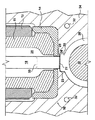
図1および図2を参照すると、この現象をはっきり見ることができる。当技術分野ではよく知られているように、ノズル・アセンブリ10が細長いノズル・ブッシュ12を含み、この中にノズル先端16が同軸に取り付けられている。任意選択で、断熱材14をノズル先端16の近位端に取り付け、これによって加熱されたノズル・アセンブリ10を冷却されたキャビティ・プレート34から断熱する。可動バルブ部材18はノズル・アセンブリ10の中に同軸に延在し、通路/ゲート域22の中または外に選択可能に位置決めされる。溶融物チャネル20はバルブ部材18を囲み、ノズル・アセンブリ10の長さ方向に延びていて、流動可能な材料を金型キャビティ28に連絡させる。バルブ部材18が(図1に示すように)完全に閉じた位置に置かれると、キャビティ・プレート34における封止部分25はバルブ部材18を封止するように包囲して、金型キャビティ28への材料の流れを遮断する。図1に示すように、バルブ部材18の面部分21は成形品の痕跡部26の全体的な頂部を画定する。バルブ部材のゲート域への案内を助け、バルブ部材とキャビティ・プレート34の摩耗を減少させるために、バルブ部材18の面に沿って面取り部36が一般的に設けられている。
【0009】
バルブ部材18は封止部分25に緊密に適合しているので、これらのそれぞれの間に存在するいかなる不整合も、バルブ部材18が封止部分25の表面に突き当たる原因になり、これが結局、封止部分25および/またはバルブ部材18の劣化を引き起すことになる。
【0010】
射出サイクルの終りに、バルブ部材18は先に説明したようにその閉位置に移動し、金型キャビティは、溶融材料が冷却し固化することを可能にするように所定のサイクル時間だけコア30とともに閉位置に保持され、それによって成形品を形成する。いったん成形品が十分なレベルにまで冷却されると、コア30とこの上の成形品とは、矢印Aによって示されたような方向に動かされ、痕跡部26はバルブ部材18の面部分21から引き離される。バルブ部材18と封止部分25との間にかなりの摩耗が存在する場合には、少量の溶融材料がその中に移動し、金型のコア30と成形品27が開放位置に動かされる際、剥離された縁部38を成形品27の痕跡部26の上に形成する。
【0011】
また、ゲートが開いているときには、バルブ部材18は、溶融材料の流れの中にあるのでかなり熱くなる可能性がある。ゲートがバルブ部材18によって閉じられると、金型キャビティ28が冷却されるときにバルブ部材18の熱い先端を冷却することが困難になる可能性があり、この結果、必要な冷却ができるようにサイクル時間を延ばすことが必要になる可能性があり、また、成形品27に望ましくない特性が生じる可能性がある。特に、バルブ部材18に隣接する金型キャビティ28内の材料は該熱い先端によって十分に冷却されないので、PET(ポリエチレンテレフタレート)などの熱に敏感な材料から成形された部分は、大きな結晶化域40またはその他の望ましくない特性域によって害されることがある。さらに、痕跡部26の全頂表面が熱いバルブ部材18の面部分21と接触しているので、面部分21に隣接する溶融材料は多少溶融した糸曳き状態のままであり、金型が開かれると不均一な縁部が形成される。
したがって、従来技術の欠点のいくつかまたは全部を減少または除去するバルブ・ゲート・システムを有する改善された射出成形機が必要となる。
【特許文献1】米国特許第2878515号
【特許文献2】米国特許第3023458号
【特許文献3】米国特許第3530539号
【発明の開示】
【発明が解決しようとする課題】
【0012】
本発明の主要な目的は、従来の技術の欠点を減少または除去するバルブ・ゲート・システムを有する改善された射出成形システムを提供することである。
本発明の別の目的は、成形品の痕跡部に沿って剥離された縁部の形成を減少または除去する射出成形システムにおいてバルブ部材と相互作用するインサートを提供することである。
本発明のさらに別の目的は、容易に取り替えることができるバルブ部材に隣接する金型プレートの中にゲート・インサートを提供することである。
【課題を解決するための手段】
【0013】
上述の目的は、痕跡部の周囲が痕跡部の内部よりも急速に冷却されるようにバルブ部材の断面積よりも大きな痕跡部断面積を有する、金型キャビティを提供することによって達成される。別の好ましい実施形態では、バルブ部材をゲートとの封止位置に案内することを助けるために、取替え可能なインサートが設けられる。このインサートの取替えは、インサートの摩耗が所定の容認されないレベルに達するといつでも、容易に実施することができる。
本発明の他の目的および利点。
【発明を実施するための最良の形態】
【0014】
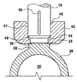
図3を参照すると、本発明による射出成形ノズル・アセンブリ10が、流動可能な材料を金型キャビティ28に連絡させてこの中に成形品を形成するために、キャビティ・プレート34の中に置かれている。キャビティ・プレート34はその中に複数の冷却流体通路32を備え、キャビティ・プレートからの熱を除去するための冷却流体を通して、金型キャビティ28の中の流動可能な材料を冷却して固化する。
【0015】
当技術分野でよく知られているように、ノズル・アセンブリ10は、細長いノズル・ブッシュ12と、この近位端に取り付けられたノズル先端部16とを含む。好ましい一実施形態では、ノズル先端部16はノズル・ブッシュ12に螺着されるが、この種の適切ないかなる手段でも使用することができる。一般的に、流動可能な材料を粘性状態に維持するために、ヒータ17をノズル・アセンブリ10の周りに巻きつける。この好ましい実施形態では、ホット・ノズル・チップ16から冷却されたキャビティ・プレート34への熱の伝達を減少させるために、任意選択の断熱材14をホット・ノズル・チップ16と冷却されたキャビティ・プレート34との間に配置している。ノズル・アセンブリ10内に、同軸に可動バルブ部材18が配置され、このバルブ部材18は金型キャビティ28の痕跡部(vestige)26に隣接して延びている。好ましい一実施形態では、バルブ部材18は、上昇して開位置へ、また、下降して閉位置へそれぞれ移動する細長い円筒状の部材である。バルブ部材18が点線50に示すような開位置にあるときには、溶融物チャネル20の中の流動可能な材料は金型キャビティ28に入ることができる。図1に示すように閉位置にあるときには、バルブ部材18は封止部分25と封止連絡状態にあり、これによって金型キャビティ28への材料の流れを停止させる。
【0016】
好ましい一実施形態では、中に形成された通路41を有するインサート部42が、キャビティ・プレート34内に設けられた空洞(cavity)44の中に、バルブ部材18と整合されて配置されている。この構成においては、封止部分25がこの交換可能なインサート部42の中にあり、バルブ部材18の周りの漏洩が始まったときに容易なメンテナンスを可能にする。
【0017】
インサート部42は、バルブ部材18がまず通路41に入るときにバルブ部材18の案内を助けるための第1面取り部46と、バルブ部材18をさらに封止部分25の中へ案内することを助けるための第2面取り部48を随意に備えることができる。これらの面取り部は、バルブ部材18とインサート部42両方の摩耗を減少し、両構成部分の耐用寿命を長くするように作用する。
【0018】
痕跡部26は、図に示すように、バルブ部材18の面部分21よりも大きな断面積を有する。従って、痕跡部26の一部分23はインサート42と熱的に連絡している。インサート42が、冷却されるキャビティ・プレート34の中に配置されていることを考えると、インサート42は、熱いバルブ部材18の表面部分21と接触している部分よりも速く、部分23を冷却することになる。この差異による冷却作用によって、部分23は表面部分21に隣接する区域より先に固化することができる。成形品を金型キャビティ28から除去するために、コア30を退避させると、この固化した部分23は従来の技術よりもきれいに離脱する傾向がある。さらに、封止部分25の位置が内部にあって、かつ、仕上がりの痕跡部26の外側表面からずれているので、金型を開いたときに起り得る裂けが減少または排除される。これは、裂け目が従来の技術におけるように痕跡部/予備成形物(preform)の表面上にないからである。
【0019】
図5に示すように、このきれいな離脱は結果として、これまでに見たものよりも均一で平坦な痕跡部26をもたらす。さらに、痕跡部26の冷却が改善されたために、減少された結晶化域40が成形品27の内部に形成されることになる。
【0020】
図3aを参照すると、インサート部42が除去されていることを除いて、図3の実施形態と同じである、本発明による代替実施形態が示されている。図3aに示すように、封止部分25はここではキャビティ・プレート34中に位置する。部分23の冷却は、痕跡部26の残り部分よりもさらに速く起こり、これによって、金型のコア30を退避させるときにほぼ完璧な離脱が可能になる。
【0021】
図4aおよび図4b(同様な特徴部分には同様な番号が付けられている)は、インサート部42およびバルブ部材18の代替実施形態を示す。図4aに示すように、バルブ部材18は痕跡部26の近くに面取り部54を有する。バルブ部材の直径が縮小された部分は、閉位置にあるときに封止部分25と封止連絡状態にある。少なくとも1つの細長い凹部56がバルブ部材18の表面に形成され、これによって、バルブ部材18を閉位置に持ってきたときにバルブ部材18に沿って流動可能な材料を押し戻すことを可能にする。面取り部46および48は、バルブ部材18が通路41に入って封止部分25に着座するときに、バルブ部材18の案内を助ける。図4bはバルブ部材18を、まさしく底部の面取り部まで1つの連続的な円筒として示す。インサート42内の通路41はまた、面取り部46におけるリード(lead)を除いて、その長さのほとんどが均一の直径である。この実施形態では、封止部分25を長くすることができ、長寿命の封止部を備えることができる。凹部56によって、バルブ部材18を閉位置に持ってきたときに、流動可能な材料は通路41から流出することができる。
【0022】
本発明は本明細書に説明した例示に限られるものではなく、この例示は本発明を実施する最良実施形態を例示しようとするものであり、形状、寸法、部品配置、および作動の詳細の変更ができることを理解されたい。本発明は、特許請求の範囲に定義されるようなその精神と範囲内にあるこのような変更のすべてを含むことを意図するものである。
【図面の簡単な説明】
【0023】
【図1】従来の技術による射出成形ノズルの簡略化した断面図である。
【図2】従来の技術による成形品の部分断面図である。
【図3】本発明による例示的な実施形態の簡略化された断面図である。
【図3a】本発明による例示的な実施形態の簡略化された断面図である。
【図4a】本発明による別の例示的な実施形態の部分断面図である。
【図4b】本発明による別の例示的な実施形態の部分断面図である。
【図5】成形品の簡略化された部分断面図である。【Technical field】
[0001]
The present invention relates to an injection molding system. More particularly, the present invention relates to valve-gated systems found in injection molding systems.
[Background Art]
[0002]
Injection molding nozzles are well known and have been used to inject a material such as plastic into a mold cavity. For example, such nozzles receive molten material, such as plastic, from an injection molding machine and direct the molten material into a mold cavity through a passage called a gate. The transfer of molten material through the gate must be stopped before the injection operation is completed and before opening the mold cavity to remove the molded part. Generally, there are two ways to stop the transfer of molten material through the gate. That is, a thermal gate or open gate, and a valve gate.
[0003]
In a thermal gate, the gate is an open opening through which the molten material passes during the injection operation. The gate cools rapidly at the end of the injection portion of the cycle, allowing the injected material to "solidify" into the plug when the injection molding pressure is removed. This plug remains in the gate and prevents molten material from dripping from the gate when the mold is open to remove the molded part. In the next injection part of the cycle, the cooling applied to the gate is removed and the hot molten material from the injection molding machine pushes the plug into the mold cavity, where the molten material melts and is newly supplied Mix with molten material.
[0004]
In a valve gate, opening and closing of the gate is independent of injection pressure and / or cooling and is achieved mechanically by a valve stem. The valve stem establishes an open position where the flow of molten material through the gate is possible and the closure of the gate by entry of the valve stem into the gate, preventing molten material from passing through the gate. It can be moved between the closed position. Valve gates are well known and examples of such systems are shown in U.S. Patent Nos. 2,878,515, 3,023,458, and 3,530,539, each of which is incorporated herein by reference. ing.
[0005]
In general, for situations where aesthetic improvements are required, valve gates are preferred over thermal gates because they can reduce the undesirable gate traces that can remain on the finished molded part. However, there are problems with valve gate systems.
[0006]
Specifically, the valve stem and the gate each have complementary sealing portions that are brought into contact to seal the gate. Typically, there is a diametric gap between the valve stem and the gate sealing portion of 0.001 to 0.002 inches. Slight misalignment of the stem with the gate causes the stem to collide with the gate seal, as the stem moves to provide a seal and aligns with the sealed portion of the gate. Over time, this causes wear and distortion of the gate area. If the gate seal area wears, the valve stem no longer stops the flow of molten material, and a small amount of molten material moves between the valve stem and the worn gate seal area. This leakage adversely affects the quality of the traces, as the solidified material between the gate and the valve stem when the mold is opened creates tears or defects along the traces in the molded article. In some cases, tears may spread on the surface of the molded article or preform.
[0007]
Following the injection cycle, typically half of the mold is opened and the somewhat solidified part is removed from the stem / gate area. Due to the confinement of the molten material between the worn gate area and the valve stem, the molded article does not come off cleanly when the mold is opened, but rather is stripped from the gate area, resulting in a molded article. There are traces with scratches on the top.
[0008]
This phenomenon can be clearly seen with reference to FIGS. As is well known in the art,
[0009]
Since the
[0010]
At the end of the injection cycle, the
[0011]
Also, when the gate is open,
Accordingly, there is a need for an improved injection molding machine having a valve gate system that reduces or eliminates some or all of the disadvantages of the prior art.
[Patent Document 1] U.S. Pat. No. 2,787,515 [Patent Document 2] U.S. Pat. No. 3,023,458 [Patent Document 3] U.S. Pat. No. 3,530,539 [Disclosure of the Invention]
[Problems to be solved by the invention]
[0012]
A primary object of the present invention is to provide an improved injection molding system having a valve gate system that reduces or eliminates the disadvantages of the prior art.
It is another object of the present invention to provide an insert that interacts with a valve member in an injection molding system that reduces or eliminates the formation of peeled edges along a trace of a molded article.
It is yet another object of the present invention to provide a gate insert in a mold plate adjacent to a valve member that can be easily replaced.
[Means for Solving the Problems]
[0013]
The above objective is accomplished by providing a mold cavity having a trace cross-sectional area that is greater than the cross-sectional area of the valve member such that the periphery of the trace is cooled more quickly than the interior of the trace. In another preferred embodiment, a replaceable insert is provided to help guide the valve member to a sealing position with the gate. This replacement of the insert can be easily performed whenever the wear of the insert reaches a predetermined unacceptable level.
Other objects and advantages of the present invention.
BEST MODE FOR CARRYING OUT THE INVENTION
[0014]
Referring to FIG. 3, an injection
[0015]
As is well known in the art, the
[0016]
In one preferred embodiment, an
[0017]
The
[0018]
The
[0019]
As shown in FIG. 5, this clean disengagement results in a more uniform and
[0020]
Referring to FIG. 3a, an alternative embodiment according to the present invention is shown, which is the same as the embodiment of FIG. 3, except that the
[0021]
4a and 4b (similar features are similarly numbered) show an alternative embodiment of the
[0022]
The invention is not limited to the examples described herein, which are intended to exemplify the best mode for practicing the invention, and may vary in shape, dimensions, component arrangement, and operational details. Please understand that you can do it. The present invention is intended to embrace all such modifications that come within the spirit and scope as defined in the following claims.
[Brief description of the drawings]
[0023]
FIG. 1 is a simplified cross-sectional view of a conventional injection molding nozzle.
FIG. 2 is a partial cross-sectional view of a molded product according to a conventional technique.
FIG. 3 is a simplified cross-sectional view of an exemplary embodiment according to the present invention.
FIG. 3a is a simplified cross-sectional view of an exemplary embodiment according to the present invention.
FIG. 4a is a partial cross-sectional view of another exemplary embodiment according to the present invention.
FIG. 4b is a partial cross-sectional view of another exemplary embodiment according to the present invention.
FIG. 5 is a simplified partial sectional view of a molded product.
Claims (36)
各ノズルにおけるノズル・ゲートを通して前記流動可能な材料の連絡を、選択的に開始および停止するための、所定の断面積を有する可動バルブ部材と、
前記物品の表面から突き出た、前記ノズル・ゲートに隣接する痕跡部とを有し、前記痕跡部が前記バルブ部材の前記断面積より大きな断面積を有する、装置。An apparatus for injection molding at least one article, comprising: at least one mold cavity; and a supply of flowable material communicated to said mold cavity through at least one injection nozzle.
A movable valve member having a predetermined cross-sectional area for selectively starting and stopping the flowable material communication through a nozzle gate in each nozzle;
A mark protruding from a surface of the article and adjacent to the nozzle gate, the mark having a cross-sectional area greater than the cross-sectional area of the valve member.
溶融物通路を有し、前記金型キャビティと整合したキャビティ・プレートの空洞内に配置された細長いノズル・ブッシュと、
前記ノズル・ブッシュから前記金型キャビティへの流動可能な材料の連絡のために前記ノズル・ブッシュに取り付けられたノズル先端部と、
前記射出ノズルと熱的に連絡しているヒータと
を備える、
請求項1に記載の装置。The injection nozzle,
An elongated nozzle bushing having a melt passage and disposed within a cavity of a cavity plate aligned with the mold cavity;
A nozzle tip attached to the nozzle bush for communicating flowable material from the nozzle bush to the mold cavity;
Comprising a heater in thermal communication with the injection nozzle.
The device according to claim 1.
前記出口を通る前記流動可能な材料の連絡を、選択的に開始および停止するための可動バルブ部材と
を含み、
前記物品は、前記バルブ部材に隣接する痕跡部を有し、前記バルブ部材の断面積は前記痕跡部よりも小さい、射出成形するための装置。A device for injection molding at least one article, the source of flowable material in fluid communication with at least one injection nozzle having an outlet aligned with a mold cavity for forming the article;
A movable valve member for selectively starting and stopping communication of the flowable material through the outlet;
The apparatus for injection molding, wherein the article has a trace adjacent the valve member, wherein the cross-sectional area of the valve member is smaller than the trace.
溶融物通路を有し、前記金型キャビティと整合したキャビティ・プレートの空洞内に配置された細長いノズル・ブッシュと、
前記ノズル・ブッシュから前記金型キャビティへの流動可能な材料の連絡のために前記ノズル・ブッシュに取り付けられたノズル先端部と、
前記射出ノズルと熱的に連絡しているヒータと
を備える、
請求項13に記載の装置。The injection nozzle,
An elongated nozzle bushing having a melt passage and disposed within a cavity of a cavity plate aligned with the mold cavity;
A nozzle tip attached to the nozzle bush for communicating flowable material from the nozzle bush to the mold cavity;
Comprising a heater in thermal communication with the injection nozzle.
An apparatus according to claim 13.
少なくとも1つの射出ノズルと流体連通する少なくとも1つの溶融物通路を有するマニホールド構造と、
コアと離隔して整合するキャビティ・プレートであって、これらの間にキャビティを形成し、前記ノズルが該キャビティ中に成形品を形成するためにノズル・ゲートを通して前記キャビティと流体連通している、キャビティ・プレートと、
前記ノズルと前記ノズル・ゲートとの間に流体連通している通路を有しているインサートと、
前記流動可能な材料の前記キャビティへの連絡を選択的に停止および開始するための可動バルブ部材と
を備え、
前記ノズル・ゲートが、前記成形品から突出する痕跡部に隣接し、前記バルブ部材に隣接する前記痕跡部の断面積が、前記成形品と接触する前記バルブ部材の断面積よりも大きい、
射出成形システム。In an injection molding system, a manifold subsystem for communicating flowable materials comprises:
A manifold structure having at least one melt passage in fluid communication with at least one injection nozzle;
A cavity plate spaced from and aligned with the core, defining a cavity therebetween, wherein the nozzle is in fluid communication with the cavity through a nozzle gate to form a molded article in the cavity; A cavity plate,
An insert having a passage in fluid communication between the nozzle and the nozzle gate;
A movable valve member for selectively stopping and starting communication of the flowable material to the cavity;
The nozzle gate is adjacent to a trace protruding from the molded product, and a cross-sectional area of the trace adjacent to the valve member is larger than a cross-sectional area of the valve member in contact with the molded product.
Injection molding system.
溶融物通路を有し、前記金型キャビティと整合したキャビティ・プレートの空洞内に配置された細長いノズル・ブッシュと、
前記ノズル・ブッシュから前記金型キャビティへの前記流動可能な材料の連絡のために前記ノズル・ブッシュに取り付けられたノズル先端部と、
前記射出ノズルと熱的に連絡しているヒータと
を備える、
請求項25に記載の装置。The injection nozzle,
An elongated nozzle bushing having a melt passage and disposed within a cavity of a cavity plate aligned with the mold cavity;
A nozzle tip attached to the nozzle bush for communication of the flowable material from the nozzle bush to the mold cavity;
Comprising a heater in thermal communication with the injection nozzle.
An apparatus according to claim 25.
流体を金型キャビティに連絡するために射出ノズル・アセンブリと金型キャビティとの間に位置する通路が中に形成された本体と、
バルブ部材が開口部に隣接したとき、前記キャビティへの前記流体の流れが妨げられるように可動バルブ部材と封止連絡する前記通路の開口部と、
前記ゲート・インサートおよび前記バルブ部材と熱的に連絡する隆起部分とを有し、前記隆起部分の外側周囲を前記隆起部分の内部よりも速く冷却させる射出成形システム。In an injection molding system for forming a molded article, a gate insert is
A body having a passage formed therein between the injection nozzle assembly and the mold cavity for communicating fluid to the mold cavity;
An opening in the passage in sealing communication with a movable valve member such that flow of the fluid to the cavity is obstructed when the valve member is adjacent to the opening;
An injection molding system having a raised portion in thermal communication with the gate insert and the valve member, wherein the outer periphery of the raised portion cools faster than the interior of the raised portion.
Applications Claiming Priority (2)
| Application Number | Priority Date | Filing Date | Title |
|---|---|---|---|
| US09/900,083 US20030008034A1 (en) | 2001-07-06 | 2001-07-06 | Method and apparatus for injection molding articles |
| PCT/CA2002/000774 WO2003004243A1 (en) | 2001-07-06 | 2002-05-27 | Method and apparatus for injection molding articles |
Publications (2)
| Publication Number | Publication Date |
|---|---|
| JP2004520984A true JP2004520984A (en) | 2004-07-15 |
| JP2004520984A5 JP2004520984A5 (en) | 2006-04-13 |
Family
ID=25411944
Family Applications (1)
| Application Number | Title | Priority Date | Filing Date |
|---|---|---|---|
| JP2003510234A Ceased JP2004520984A (en) | 2001-07-06 | 2002-05-27 | Method and apparatus for injection molding articles |
Country Status (10)
| Country | Link |
|---|---|
| US (2) | US20030008034A1 (en) |
| EP (1) | EP1406754B1 (en) |
| JP (1) | JP2004520984A (en) |
| CN (2) | CN100398295C (en) |
| AT (1) | ATE369964T1 (en) |
| CA (1) | CA2449179A1 (en) |
| DE (1) | DE60221845T2 (en) |
| ES (1) | ES2291468T3 (en) |
| TW (1) | TW590870B (en) |
| WO (1) | WO2003004243A1 (en) |
Cited By (1)
| Publication number | Priority date | Publication date | Assignee | Title |
|---|---|---|---|---|
| JP2013523497A (en) * | 2010-04-05 | 2013-06-17 | ハスキー インジェクション モールディング システムズ リミテッド | Mold tool assembly including a resin retaining mechanism positioned against a stem tip |
Families Citing this family (33)
| Publication number | Priority date | Publication date | Assignee | Title |
|---|---|---|---|---|
| US6769901B2 (en) * | 2000-04-12 | 2004-08-03 | Mold-Masters Limited | Injection nozzle system for an injection molding machine |
| US7156651B2 (en) * | 2001-07-06 | 2007-01-02 | Husky Injection Molding Systems Ltd. | Apparatus for injection molding articles |
| CA2358187A1 (en) * | 2001-10-03 | 2003-04-03 | Mold-Masters Limited | Nozzle seal |
| CA2358148A1 (en) * | 2001-10-03 | 2003-04-03 | Mold-Masters Limited | A nozzle |
| US6962492B2 (en) * | 2001-10-05 | 2005-11-08 | Mold-Masters Limited | Gap seal between nozzle components |
| US7128566B2 (en) * | 2002-02-21 | 2006-10-31 | Mold-Masters Limited | Valve pin guiding tip for a nozzle |
| CA2473920A1 (en) | 2002-02-21 | 2003-08-28 | Mold-Masters Limited | A valve pin guide for a valve-gated nozzle |
| DE10392533B4 (en) * | 2002-04-12 | 2014-07-03 | Mold-Masters (2007) Limited | Injection molding device with a mold gate insert with thermal lock |
| EP1531977B1 (en) * | 2002-07-30 | 2007-09-19 | Mold-Masters Limited | A valve pin guide and alignment system for a hot-runner in an injection molding apparatus |
| CA2450411C (en) * | 2002-11-21 | 2012-01-03 | Mold-Masters Limited | Hot runner nozzle with a tip, a tip surrounding piece and an alignment piece |
| DE10356937A1 (en) * | 2002-12-09 | 2004-07-15 | Mold-Masters Ltd., Georgetown | Nozzle for injection molding apparatus comprises nozzle body, heater, tip, tip surrounding piece, and seal piece |
| US7217120B2 (en) * | 2004-06-16 | 2007-05-15 | V-Tek Molding Technologies Inc. | Hot runner nozzle |
| US20070040292A1 (en) * | 2005-08-22 | 2007-02-22 | Fina Technology, Inc. | Polypropylene composition for high gloss retention |
| US7661947B2 (en) * | 2005-11-21 | 2010-02-16 | Epoch Composite Products, Inc. | Method and apparatus for molding roofing products with back gating |
| CN100553924C (en) * | 2006-01-18 | 2009-10-28 | 鸿富锦精密工业(深圳)有限公司 | Forming die for optical element |
| US7458795B2 (en) * | 2006-02-24 | 2008-12-02 | Incoe Corporation | Co-injection nozzle assembly |
| US7589138B2 (en) * | 2006-12-05 | 2009-09-15 | Fina Technology, Inc. | Injection molding process |
| US7566216B2 (en) | 2007-04-29 | 2009-07-28 | Husky Injection Molding Systems Ltd. | Mold assembly using inserts |
| US7568906B2 (en) | 2007-04-30 | 2009-08-04 | Husky Injection Molding Systems Ltd. | Mold assembly using inserts |
| US7513772B2 (en) * | 2007-05-09 | 2009-04-07 | Mold-Masters (2007) Limited | Injection molding nozzle with valve pin alignment |
| US7854876B2 (en) | 2007-05-25 | 2010-12-21 | Ecovision Technologies, Llc | Apparatus and methods for modular preform mold system |
| EP1997603A1 (en) * | 2007-05-31 | 2008-12-03 | Alliance for business solutions A4BS | Modified hot runner systems for injection blow molding |
| US7866974B2 (en) * | 2008-03-18 | 2011-01-11 | Husky Injection Molding Systems Ltd. | Melt distribution apparatus for use in a hot runner |
| CN101590686B (en) * | 2008-05-26 | 2013-08-14 | 鸿富锦精密工业(深圳)有限公司 | Setting method for valve action |
| US7972132B2 (en) * | 2008-10-10 | 2011-07-05 | Mold-Masters (2007) Ltd | Injection molding valve gated hot runner nozzle |
| US8449287B2 (en) | 2010-09-10 | 2013-05-28 | Mold-Masters (2007) Limited | Valve pin for accommodating side loading |
| EP3092115B1 (en) * | 2014-01-08 | 2018-06-06 | Synventive Molding Solutions, Inc. | Valve pin and nozzle configuration and method of control |
| DE102014210333A1 (en) * | 2014-06-02 | 2015-12-03 | AWETIS Engineering + Manufacturing GmbH | Injection mold for sprayed material |
| DE102014210332A1 (en) * | 2014-06-02 | 2015-12-03 | AWETIS Engineering + Manufacturing GmbH | Injection nozzle for introducing sprayed material into an injection mold |
| US9248595B2 (en) | 2014-06-24 | 2016-02-02 | Athena Automation Ltd. | Hot runner apparatus for an injection molding machine |
| JP6792397B2 (en) * | 2016-09-30 | 2020-11-25 | 小林製薬株式会社 | Manufacturing method of interdental cleaning tool |
| CN106994767A (en) * | 2017-05-05 | 2017-08-01 | 浙江思纳克热流道科技有限公司 | Carry the needle structure of guide-localization |
| IT202100031877A1 (en) * | 2021-12-20 | 2023-06-20 | Inglass S P A Con Socio Unico | “Improved tip for injection molding” |
Family Cites Families (16)
| Publication number | Priority date | Publication date | Assignee | Title |
|---|---|---|---|---|
| US4108956A (en) * | 1977-01-21 | 1978-08-22 | Owens-Illinois, Inc. | Injection molding method and apparatus |
| CA1132321A (en) * | 1979-07-20 | 1982-09-28 | Mold-Masters Limited | Injection molding filter assembly |
| CA1136815A (en) * | 1980-07-15 | 1982-12-07 | Jobst U. Gellert | Injection molding nozzle seal |
| CA1261579A (en) * | 1987-03-19 | 1989-09-26 | Mold-Masters Limited | Replaceable rocker arm assembly for injection molding system |
| US5254305A (en) | 1987-12-10 | 1993-10-19 | Otto Hofstetter Ag | Injection nozzle and method for charging an injection nozzle |
| JP3222894B2 (en) * | 1991-04-10 | 2001-10-29 | 田中貴金属工業株式会社 | Platinum group metal recovery method |
| DE59404200D1 (en) | 1993-08-13 | 1997-11-06 | Awm Werkzeugbau Ag | Spray nozzle |
| CA2175634C (en) * | 1996-05-02 | 2007-08-21 | Klaus Bauer | Injection molding valve member with head and neck portions |
| EP0836925A1 (en) * | 1996-10-09 | 1998-04-22 | EUROTOOL Beheer B.V. | Valve-gated injection moulding device |
| US6056536A (en) * | 1997-03-20 | 2000-05-02 | Husky Injection Molding Systems Ltd. | Valve gating apparatus for injection molding |
| US6135757A (en) * | 1998-10-16 | 2000-10-24 | Husky Injection Systems Ltd. | Valve gated injection molding system |
| US6318990B1 (en) * | 1998-10-16 | 2001-11-20 | Mold-Masters Limited | Injection molding nozzle apparatus |
| US6168416B1 (en) | 1998-12-22 | 2001-01-02 | Husky Injection Molding Systems Ltd. | Cooling device for molded articles |
| US6220850B1 (en) * | 1999-02-16 | 2001-04-24 | Husky Injection Molding Systems Ltd. | Mold gate insert |
| US6214275B1 (en) * | 1999-06-04 | 2001-04-10 | Husky Injection Molding Systems Ltd. | Injection nozzle and method for injection molding |
| US6220891B1 (en) * | 1999-06-24 | 2001-04-24 | Zetec, Inc. | Probe connector |
-
2001
- 2001-07-06 US US09/900,083 patent/US20030008034A1/en not_active Abandoned
-
2002
- 2002-05-27 ES ES02729720T patent/ES2291468T3/en not_active Expired - Lifetime
- 2002-05-27 WO PCT/CA2002/000774 patent/WO2003004243A1/en active IP Right Grant
- 2002-05-27 EP EP02729720A patent/EP1406754B1/en not_active Expired - Lifetime
- 2002-05-27 DE DE60221845T patent/DE60221845T2/en not_active Expired - Fee Related
- 2002-05-27 AT AT02729720T patent/ATE369964T1/en not_active IP Right Cessation
- 2002-05-27 CN CNB2005100737502A patent/CN100398295C/en not_active Expired - Fee Related
- 2002-05-27 JP JP2003510234A patent/JP2004520984A/en not_active Ceased
- 2002-05-27 CN CNA028136454A patent/CN1537045A/en active Pending
- 2002-05-27 CA CA002449179A patent/CA2449179A1/en not_active Abandoned
- 2002-05-31 TW TW091111704A patent/TW590870B/en not_active IP Right Cessation
-
2003
- 2003-09-25 US US10/670,870 patent/US7037103B2/en not_active Expired - Fee Related
Cited By (1)
| Publication number | Priority date | Publication date | Assignee | Title |
|---|---|---|---|---|
| JP2013523497A (en) * | 2010-04-05 | 2013-06-17 | ハスキー インジェクション モールディング システムズ リミテッド | Mold tool assembly including a resin retaining mechanism positioned against a stem tip |
Also Published As
| Publication number | Publication date |
|---|---|
| TW590870B (en) | 2004-06-11 |
| US20030008034A1 (en) | 2003-01-09 |
| CN1680085A (en) | 2005-10-12 |
| ES2291468T3 (en) | 2008-03-01 |
| CN100398295C (en) | 2008-07-02 |
| EP1406754B1 (en) | 2007-08-15 |
| WO2003004243A1 (en) | 2003-01-16 |
| EP1406754A1 (en) | 2004-04-14 |
| US20040058031A1 (en) | 2004-03-25 |
| US7037103B2 (en) | 2006-05-02 |
| CN1537045A (en) | 2004-10-13 |
| ATE369964T1 (en) | 2007-09-15 |
| DE60221845D1 (en) | 2007-09-27 |
| CA2449179A1 (en) | 2003-01-16 |
| DE60221845T2 (en) | 2008-05-08 |
Similar Documents
| Publication | Publication Date | Title |
|---|---|---|
| JP2004520984A (en) | Method and apparatus for injection molding articles | |
| KR100296953B1 (en) | Molding method and apparatus of plastic product | |
| WO2005110701A1 (en) | Improved apparatus for injection molding articles | |
| US5871786A (en) | Tip heated hot runner nozzle | |
| US4666396A (en) | Thermally insulated heated sprue bushing in plastic molding apparatus | |
| JPH10296799A (en) | Injection molding device having integral gate insert having cylindrically shaped valve member disposed therein | |
| IT8048576A1 (en) | DEVICE FOR CASTING UNDER PRESSURE WITHOUT SPRING OF POLYMERIC ARTICLES. | |
| CA2453170A1 (en) | Lateral gating injection molding apparatus | |
| JP2008520457A (en) | Improved valve gate for hot runner injection molding machines. | |
| JPH11216745A (en) | Side gate type injection molding equipment with actuating manifold | |
| US5219593A (en) | Injection molding apparatus | |
| US5037598A (en) | Reciprocating heated nozzle | |
| EP1732742A1 (en) | Injection device | |
| JPH07148786A (en) | Injection molding apparatus | |
| CA2515404A1 (en) | Method for producing mould parts by injection and plugged needle nozzle for an injection mould | |
| JP2010094937A (en) | Side valve gate type hot runner system | |
| KR100739013B1 (en) | A mould assembly | |
| WO2023154994A1 (en) | Injection mold component | |
| CN113825613A (en) | Injection molding device | |
| JP2002018910A (en) | Structure of valve gate of mold for injection molding and molding | |
| JP2001047468A (en) | Spool bush for injection molding and mold for injection molding | |
| JP2003071880A (en) | Valve gate type mold apparatus | |
| JP2003191290A (en) | Injection mold assembly | |
| EP0130986A1 (en) | Insulated sprue bushing in plastic molding apparatus | |
| JP2002337187A (en) | Injection molding device and injection molding method |
Legal Events
| Date | Code | Title | Description |
|---|---|---|---|
| A521 | Request for written amendment filed |
Free format text: JAPANESE INTERMEDIATE CODE: A523 Effective date: 20060227 |
|
| A977 | Report on retrieval |
Free format text: JAPANESE INTERMEDIATE CODE: A971007 Effective date: 20061017 |
|
| A131 | Notification of reasons for refusal |
Free format text: JAPANESE INTERMEDIATE CODE: A131 Effective date: 20061025 |
|
| A601 | Written request for extension of time |
Free format text: JAPANESE INTERMEDIATE CODE: A601 Effective date: 20070125 |
|
| A602 | Written permission of extension of time |
Free format text: JAPANESE INTERMEDIATE CODE: A602 Effective date: 20070201 |
|
| A521 | Request for written amendment filed |
Free format text: JAPANESE INTERMEDIATE CODE: A523 Effective date: 20070420 |
|
| A01 | Written decision to grant a patent or to grant a registration (utility model) |
Free format text: JAPANESE INTERMEDIATE CODE: A01 Effective date: 20090202 |
|
| A045 | Written measure of dismissal of application [lapsed due to lack of payment] |
Free format text: JAPANESE INTERMEDIATE CODE: A045 Effective date: 20090622 |