JP2004512550A - Optical fiber optical waveguide - Google Patents
Optical fiber optical waveguide Download PDFInfo
- Publication number
- JP2004512550A JP2004512550A JP2002536584A JP2002536584A JP2004512550A JP 2004512550 A JP2004512550 A JP 2004512550A JP 2002536584 A JP2002536584 A JP 2002536584A JP 2002536584 A JP2002536584 A JP 2002536584A JP 2004512550 A JP2004512550 A JP 2004512550A
- Authority
- JP
- Japan
- Prior art keywords
- waveguide
- optical waveguide
- optical
- core
- waveguides
- Prior art date
- Legal status (The legal status is an assumption and is not a legal conclusion. Google has not performed a legal analysis and makes no representation as to the accuracy of the status listed.)
- Pending
Links
Images


Classifications
-
- D—TEXTILES; PAPER
- D04—BRAIDING; LACE-MAKING; KNITTING; TRIMMINGS; NON-WOVEN FABRICS
- D04C—BRAIDING OR MANUFACTURE OF LACE, INCLUDING BOBBIN-NET OR CARBONISED LACE; BRAIDING MACHINES; BRAID; LACE
- D04C1/00—Braid or lace, e.g. pillow-lace; Processes for the manufacture thereof
- D04C1/06—Braid or lace serving particular purposes
-
- D—TEXTILES; PAPER
- D04—BRAIDING; LACE-MAKING; KNITTING; TRIMMINGS; NON-WOVEN FABRICS
- D04C—BRAIDING OR MANUFACTURE OF LACE, INCLUDING BOBBIN-NET OR CARBONISED LACE; BRAIDING MACHINES; BRAID; LACE
- D04C1/00—Braid or lace, e.g. pillow-lace; Processes for the manufacture thereof
- D04C1/02—Braid or lace, e.g. pillow-lace; Processes for the manufacture thereof made from particular materials
-
- G—PHYSICS
- G02—OPTICS
- G02B—OPTICAL ELEMENTS, SYSTEMS OR APPARATUS
- G02B6/00—Light guides; Structural details of arrangements comprising light guides and other optical elements, e.g. couplings
- G02B6/0001—Light guides; Structural details of arrangements comprising light guides and other optical elements, e.g. couplings specially adapted for lighting devices or systems
- G02B6/0005—Light guides; Structural details of arrangements comprising light guides and other optical elements, e.g. couplings specially adapted for lighting devices or systems the light guides being of the fibre type
- G02B6/001—Light guides; Structural details of arrangements comprising light guides and other optical elements, e.g. couplings specially adapted for lighting devices or systems the light guides being of the fibre type the light being emitted along at least a portion of the lateral surface of the fibre
-
- G—PHYSICS
- G02—OPTICS
- G02B—OPTICAL ELEMENTS, SYSTEMS OR APPARATUS
- G02B6/00—Light guides; Structural details of arrangements comprising light guides and other optical elements, e.g. couplings
- G02B6/24—Coupling light guides
- G02B6/26—Optical coupling means
- G02B6/28—Optical coupling means having data bus means, i.e. plural waveguides interconnected and providing an inherently bidirectional system by mixing and splitting signals
- G02B6/2804—Optical coupling means having data bus means, i.e. plural waveguides interconnected and providing an inherently bidirectional system by mixing and splitting signals forming multipart couplers without wavelength selective elements, e.g. "T" couplers, star couplers
- G02B6/2852—Optical coupling means having data bus means, i.e. plural waveguides interconnected and providing an inherently bidirectional system by mixing and splitting signals forming multipart couplers without wavelength selective elements, e.g. "T" couplers, star couplers using tapping light guides arranged sidewardly, e.g. in a non-parallel relationship with respect to the bus light guides (light extraction or launching through cladding, with or without surface discontinuities, bent structures)
-
- D—TEXTILES; PAPER
- D10—INDEXING SCHEME ASSOCIATED WITH SUBLASSES OF SECTION D, RELATING TO TEXTILES
- D10B—INDEXING SCHEME ASSOCIATED WITH SUBLASSES OF SECTION D, RELATING TO TEXTILES
- D10B2401/00—Physical properties
- D10B2401/20—Physical properties optical
-
- G—PHYSICS
- G02—OPTICS
- G02B—OPTICAL ELEMENTS, SYSTEMS OR APPARATUS
- G02B6/00—Light guides; Structural details of arrangements comprising light guides and other optical elements, e.g. couplings
- G02B6/0001—Light guides; Structural details of arrangements comprising light guides and other optical elements, e.g. couplings specially adapted for lighting devices or systems
-
- G—PHYSICS
- G02—OPTICS
- G02B—OPTICAL ELEMENTS, SYSTEMS OR APPARATUS
- G02B6/00—Light guides; Structural details of arrangements comprising light guides and other optical elements, e.g. couplings
- G02B6/02—Optical fibres with cladding with or without a coating
- G02B6/02033—Core or cladding made from organic material, e.g. polymeric material
-
- G—PHYSICS
- G02—OPTICS
- G02B—OPTICAL ELEMENTS, SYSTEMS OR APPARATUS
- G02B6/00—Light guides; Structural details of arrangements comprising light guides and other optical elements, e.g. couplings
- G02B6/04—Light guides; Structural details of arrangements comprising light guides and other optical elements, e.g. couplings formed by bundles of fibres
-
- G—PHYSICS
- G02—OPTICS
- G02B—OPTICAL ELEMENTS, SYSTEMS OR APPARATUS
- G02B6/00—Light guides; Structural details of arrangements comprising light guides and other optical elements, e.g. couplings
- G02B6/44—Mechanical structures for providing tensile strength and external protection for fibres, e.g. optical transmission cables
- G02B6/4479—Manufacturing methods of optical cables
- G02B6/449—Twisting
Abstract
本発明によると、互いに織り合わせられたケーブルの一つ或いは複数の同心円状の層から構成される光導波路は、光の横方向の損失を制御するための複数の光ファイバ導波路を含み、これによって導波路に沿っての均質なイルミネーションが達成される。個々の導波路は、ポリメタクリル酸メチル(PMMP)から成り、フッ素樹脂のシース有する。According to the present invention, an optical waveguide composed of one or more concentric layers of cable woven together includes a plurality of optical fiber waveguides for controlling lateral loss of light, This achieves a homogeneous illumination along the waveguide. Each waveguide is made of polymethyl methacrylate (PMMP) and has a fluororesin sheath.
Description
【0001】
本発明は、現在知られている導波路とは異なる新規で、好ましい効果を有する光ファイバ光導波路を導入することを意図する。
【0002】
本発明による光導波路は、とりわけ、光の横方向の損失を制御できることを意図される。これによって、光導波路を、制御されたやり方にて、全長に沿って内側からイルミネートされた要素に変換することや、全長に渡って視感度特性(luminosity characteristics)を制御できる導波路を得ることや、シグナル用途に用いることや、文字、サイン、その他を、現在は「ネオン」管によって達成されているそれと非常に類似するやりかたにて形成することが可能となる。
【0003】
より具体的には、本発明による光導波路は、ポリメチルメタクリレート(polymethylmethacrylate,PMMA)を用いて製造され、典型的には1.495なる屈折率を有するPMMAコアを含み、典型的には1.402なる屈折率を有する透明なフッ素樹脂の膜にてカバーされる。この設計によると、この導波路に入ると、光線は、クラッドの壁に当たり、屈折率の差に生じる全反射によって光は導波路の内側最小の損失にて伝播する。ただし、PMMAコアのクラッドは完全ではないために、顕微鏡レベルのクラック(microscopic cracks)が形成され、コアの内側を伝播する光のある量は漏れ出る。
【0004】
PMMAから成るコアとフッ素樹脂から成るクラッドの同心円状の膜は、性質が異なり、これらの硬さも異なるために、導波路が湾曲されると、マイクロクラック(micor−craks)が発生し、このため光は導波路に対して横方向に漏れ出る。
【0005】
コア材によって許容される電力密度は限られているために、コア内の可視光の量も限られるために、損失の均質性や、コアの内側の光が尽きるまでにカバーできる距離は、導波路内に存在するマイクロクラックの数に依存する。
【0006】
本発明による光導波路の設計においては、とりわけ、光の横方向の損失が改善されるように設計されたアーキテクチャを組み込む互いに織り合わされた紐の構造が用いられ、これによって導波路のイルミネーションが全経路に沿って達成される。
【0007】
これを達成するためには、各アーキテクチャを得るために導波路を所定のやり方にて、ねじったり湾曲されることが必要となるが、これは、個々の光ファイバを外側の膜を損傷することなく織り合わせることができるように、ケーブルの織り合わせを制御することで達成される。
【0008】
本発明を適用することで、全長に沿ってイルミネートされた、高いレベルの均質性と、60メートル或いはそれ以上の長さを有する、一連の織り合わせられた導波路を得ることが可能となる。
【0009】
この光導波路は、複数の同心円状の層を互いに織り合わせることで形成され、個々の光導波路の横方向の応力、ねじり、及び湾曲を制御することで、横方向の損失が最適化される。
【0010】
これら導波路に対して、用途に応じて、横方向と縦方向のエミッション特性を組合せることで、様々な特性を得ることができる。これは、一連の層の構成を設計したり、層の数を適当に選択したり、中空でない、反射性の、コントラストを有する互いに織り合わせられた或いは線状のコアを用いたりすることで達成される。
【0011】
この結果として、用途に応じた異なる特徴を備えるユニークな特性を有する様々なアーキテクチャを得ることができる。例えば、幾つかの用途では、短な区間内に多量の光が得られるようにされ、別の用途では、より長い区間に渡ってより少量のエミッションが得られるようにされるが、これらを無限に変化させることが可能である。
【0012】
より理解を深める目的で、本発明による光導波路の実施例を示す幾つかの図面を、制限を意図するのではなく、単なる例示として添付する。
【0013】
【発明の実施の形態】
図面に示すように、本発明による光導波路は、本質的には、PMMA技術に従って製造された可変数の光導波路から成る個別の要素2、2’等のアセンブリ或いは層1に基づく。これら光導波路は、互いに織り合わせられ、つまり、編まれたケーブルに形成される。このケーブルには、(図1及び図2の場合のように)、反射性の、コントラストを有する中空でないコア(reflective, contrasting, solid internal core)3が設けられることも、或いは図3及び図4に示す光導波路4の場合のように中空な構造とされることもある。光導波路4の場合は、様々な個別の導波路5、5’等によって形成され、これら導波路を互いに織り合わせることで、中空なコアを有する光導波路が形成される。
【0014】
本発明による光導波路は、複数の一連の層にて形成され、内部コアは、設けられることも、設けられないこともある。例えば、図5においては、本発明による光導波路6は、個別の導波路7、7’、7”等にて形成される互いに織り合わせられた外側層と、中空でない内部コア8を有する。
【0015】
図6に示す光導波路9は、複数の互いに織り合わせられた導波路10、10’、10”によって形成され、内部コアは有さない。
【0016】
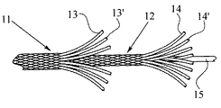
図7に示す光導波路は、外側の互いに織り合わせられたシース11と内側の互いに織り合わせられたシース12から形成され、これらは両方とも、それぞれ、個別の導波路の線、例えば、13、13’等及び14、14’等によって形成され、補完的に中空でないコア15を有する。
【0017】
図8は、3つの一連の層16、17、18と、中空でない内部コア19を有するバリエーションを示す。各々の一連の層16、17、18は、複数の個別の互いに織り合わせられた導波路によって形成される。こうして編まれたケーブルの、一つの層が次の層を覆い、全体として中空でないコア19を覆う一連の層が形成される。
【0018】
個別の導波路の織り合わせ方や特性、層の数、及び織り合わせのパラメータ、例えば張力、ねじり等を制御することで、光導波路の全長に沿ってイルミネーションを一様にしたり、各区間の均質性を増したり、区間長を増すことなどが可能となる。
【0019】
図9及び図10は、それぞれ、本発明による光導波路の構成を簡略的に示す。図9は、導波路20によって、デザイン、文字、数字等が表現する様々な一連の湾曲、例えば、21、21’等が形成される様子を示す。
【0020】
図10は、一例としての光導波路22を示す。この例においては、予め選択された湾曲を有するゾーン23、及び所望の光効果を達成するために幅を広くされた形状を有する中間ゾーン24が存在する。
【図面の簡単な説明】
【図1】
本発明に従って製造された中空でない内部コアを有する光導波路の外側を示す図である。
【図2】
本発明に従って製造された中空でない内部コアを有する光導波路の断面を示す図である。
【図3】
図1及び図2と類似するが、内部コアを有さない、換言すれば、中空な光導波路を示す図である。
【図4】
図1及び図2と類似するが、内部コアを有さない、換言すれば、中空な光導波路を示す図である。
【図5】
内部コアを有する光導波路と内部コアを有さない光導波路の外側を示す図である。
【図6】
内部コアを有する光導波路と内部コアを有さない光導波路の外側を示す図である。
【図7】
2つの一連の互いに織り合わせられた層と一つの中空でないコアを有する光導波路の構造を示す図である。
【図8】
3つの一連の層と一つの中空でない内部コアを有する光導波路の外側を簡略的に図である。
【図9】
ある光効果を達成するために光導波路を湾曲することができる様子を簡略的に示す図である。
【図10】
ある光効果を達成するために光導波路を湾曲することができる様子を簡略的に示す図である。[0001]
The present invention contemplates the introduction of a novel and advantageous optical fiber optical waveguide that is different from currently known waveguides.
[0002]
The optical waveguide according to the invention is intended, inter alia, to be able to control the lateral loss of light. This allows the optical waveguide to be converted into elements illuminated from the inside along the entire length in a controlled manner, to obtain a waveguide that can control luminosity characteristics over the entire length, It can be used for signaling applications, and forms letters, signs, etc., in a manner very similar to that currently achieved with "neon" tubes.
[0003]
More specifically, the optical waveguide according to the present invention is manufactured using polymethylmethacrylate (PMMA), and includes a PMMA core having a refractive index of typically 1.495, and typically having a refractive index of 1.495. It is covered with a transparent fluororesin film having a refractive index of 402. According to this design, upon entering the waveguide, the light strikes the cladding wall and the light propagates with minimal loss inside the waveguide due to total internal reflection resulting in a difference in refractive index. However, since the cladding of the PMMA core is not perfect, microscopic cracks are formed, and a certain amount of light propagating inside the core leaks out.
[0004]
Concentric films of a core made of PMMA and a clad made of fluororesin have different properties and their hardnesses are different, so that when the waveguide is bent, micro-cracks are generated. Light escapes laterally to the waveguide.
[0005]
Because of the limited power density allowed by the core material and the amount of visible light in the core, the homogeneity of the loss and the distance that the light inside the core can cover before it runs out are deduced. It depends on the number of microcracks present in the wave path.
[0006]
In the design of optical waveguides according to the present invention, interwoven woven structures are used which incorporate, inter alia, an architecture designed to improve the lateral loss of light, whereby the illumination of the waveguide is reduced by the full path. Achieved along.
[0007]
Achieving this requires that the waveguides be twisted or bent in a predetermined manner to achieve each architecture, but this can damage individual optical fibers to the outer membrane. This is achieved by controlling the interweaving of the cables so that they can be interwoven without the need.
[0008]
By applying the present invention, it is possible to obtain a series of interwoven waveguides illuminated along their entire length, having a high level of homogeneity and a length of 60 meters or more.
[0009]
The optical waveguide is formed by weaving a plurality of concentric layers together, and by controlling the lateral stress, torsion, and bending of the individual optical waveguides, the lateral losses are optimized.
[0010]
Various characteristics can be obtained by combining the horizontal and vertical emission characteristics of these waveguides depending on the application. This is achieved by designing the composition of the series of layers, by choosing the appropriate number of layers, and by using solid, reflective, contrasting interwoven or linear cores. Is done.
[0011]
As a result, a variety of architectures with unique characteristics with different features depending on the application can be obtained. For example, some applications allow for a greater amount of light within a short section, while other applications allow a smaller amount of emissions to be obtained over a longer section, but use these infinitely. Can be changed to
[0012]
For a better understanding, some drawings showing embodiments of the light guide according to the present invention are attached by way of example and not by way of limitation.
[0013]
BEST MODE FOR CARRYING OUT THE INVENTION
As shown in the figures, an optical waveguide according to the invention is essentially based on an assembly or
[0014]
An optical waveguide according to the present invention is formed of a series of layers, with or without an internal core. For example, in FIG. 5, an
[0015]
The optical waveguide 9 shown in FIG. 6 is formed by a plurality of
[0016]
The optical waveguide shown in FIG. 7 is formed from an outer interwoven sheath 11 and an inner
[0017]
FIG. 8 shows a variation with three
[0018]
By controlling the weaving method and characteristics of individual waveguides, the number of layers, and the parameters of weaving, such as tension and torsion, illumination can be made uniform along the entire length of the optical waveguide, and uniformity of each section can be achieved. It is possible to increase the performance and increase the section length.
[0019]
FIGS. 9 and 10 each schematically show the configuration of an optical waveguide according to the present invention. FIG. 9 shows how the
[0020]
FIG. 10 shows an
[Brief description of the drawings]
FIG.
FIG. 3 shows the outside of an optical waveguide having a solid inner core made according to the present invention.
FIG. 2
FIG. 2 shows a cross section of an optical waveguide having a solid inner core manufactured according to the present invention.
FIG. 3
FIG. 3 is a view similar to FIGS. 1 and 2 but showing no hollow core, in other words a hollow optical waveguide.
FIG. 4
FIG. 3 is a view similar to FIGS. 1 and 2 but showing no hollow core, in other words a hollow optical waveguide.
FIG. 5
It is a figure showing the outside of an optical waveguide which does not have an optical waveguide which has an inner core and an inner core.
FIG. 6
It is a figure showing the outside of an optical waveguide which does not have an optical waveguide which has an inner core and an inner core.
FIG. 7
FIG. 4 shows the structure of an optical waveguide having two series of interwoven layers and one solid core.
FIG. 8
FIG. 2 is a simplified view of the outside of an optical waveguide having three successive layers and one solid inner core.
FIG. 9
FIG. 4 is a diagram schematically illustrating a state in which an optical waveguide can be curved to achieve a certain optical effect.
FIG. 10
FIG. 4 is a diagram schematically illustrating a state in which an optical waveguide can be curved to achieve a certain optical effect.
Claims (3)
Applications Claiming Priority (2)
| Application Number | Priority Date | Filing Date | Title |
|---|---|---|---|
| ES200002470A ES2166739B1 (en) | 2000-10-16 | 2000-10-16 | OPTICAL FIBER LIGHT CONDUCTORS. |
| PCT/ES2001/000381 WO2002033456A1 (en) | 2000-10-16 | 2001-10-11 | Luminous optical fiber conductors |
Publications (2)
| Publication Number | Publication Date |
|---|---|
| JP2004512550A true JP2004512550A (en) | 2004-04-22 |
| JP2004512550A5 JP2004512550A5 (en) | 2005-06-09 |
Family
ID=8495261
Family Applications (1)
| Application Number | Title | Priority Date | Filing Date |
|---|---|---|---|
| JP2002536584A Pending JP2004512550A (en) | 2000-10-16 | 2001-10-11 | Optical fiber optical waveguide |
Country Status (6)
| Country | Link |
|---|---|
| US (1) | US20040013380A1 (en) |
| EP (1) | EP1327896A1 (en) |
| JP (1) | JP2004512550A (en) |
| AU (1) | AU2001293880A1 (en) |
| ES (1) | ES2166739B1 (en) |
| WO (1) | WO2002033456A1 (en) |
Families Citing this family (30)
| Publication number | Priority date | Publication date | Assignee | Title |
|---|---|---|---|---|
| US9017381B2 (en) | 2007-04-10 | 2015-04-28 | Biomet Sports Medicine, Llc | Adjustable knotless loops |
| US7905904B2 (en) | 2006-02-03 | 2011-03-15 | Biomet Sports Medicine, Llc | Soft tissue repair device and associated methods |
| US8137382B2 (en) | 2004-11-05 | 2012-03-20 | Biomet Sports Medicine, Llc | Method and apparatus for coupling anatomical features |
| US8088130B2 (en) | 2006-02-03 | 2012-01-03 | Biomet Sports Medicine, Llc | Method and apparatus for coupling soft tissue to a bone |
| US8128658B2 (en) | 2004-11-05 | 2012-03-06 | Biomet Sports Medicine, Llc | Method and apparatus for coupling soft tissue to bone |
| US8361113B2 (en) | 2006-02-03 | 2013-01-29 | Biomet Sports Medicine, Llc | Method and apparatus for coupling soft tissue to a bone |
| US8303604B2 (en) | 2004-11-05 | 2012-11-06 | Biomet Sports Medicine, Llc | Soft tissue repair device and method |
| US8298262B2 (en) | 2006-02-03 | 2012-10-30 | Biomet Sports Medicine, Llc | Method for tissue fixation |
| US7749250B2 (en) | 2006-02-03 | 2010-07-06 | Biomet Sports Medicine, Llc | Soft tissue repair assembly and associated method |
| US8118836B2 (en) | 2004-11-05 | 2012-02-21 | Biomet Sports Medicine, Llc | Method and apparatus for coupling soft tissue to a bone |
| US7909851B2 (en) | 2006-02-03 | 2011-03-22 | Biomet Sports Medicine, Llc | Soft tissue repair device and associated methods |
| US7601165B2 (en) | 2006-09-29 | 2009-10-13 | Biomet Sports Medicine, Llc | Method and apparatus for forming a self-locking adjustable suture loop |
| US11259792B2 (en) | 2006-02-03 | 2022-03-01 | Biomet Sports Medicine, Llc | Method and apparatus for coupling anatomical features |
| US8562645B2 (en) | 2006-09-29 | 2013-10-22 | Biomet Sports Medicine, Llc | Method and apparatus for forming a self-locking adjustable loop |
| US8597327B2 (en) | 2006-02-03 | 2013-12-03 | Biomet Manufacturing, Llc | Method and apparatus for sternal closure |
| US9078644B2 (en) | 2006-09-29 | 2015-07-14 | Biomet Sports Medicine, Llc | Fracture fixation device |
| US11311287B2 (en) | 2006-02-03 | 2022-04-26 | Biomet Sports Medicine, Llc | Method for tissue fixation |
| US8936621B2 (en) | 2006-02-03 | 2015-01-20 | Biomet Sports Medicine, Llc | Method and apparatus for forming a self-locking adjustable loop |
| US8968364B2 (en) | 2006-02-03 | 2015-03-03 | Biomet Sports Medicine, Llc | Method and apparatus for fixation of an ACL graft |
| US8801783B2 (en) * | 2006-09-29 | 2014-08-12 | Biomet Sports Medicine, Llc | Prosthetic ligament system for knee joint |
| US10517587B2 (en) | 2006-02-03 | 2019-12-31 | Biomet Sports Medicine, Llc | Method and apparatus for forming a self-locking adjustable loop |
| US8652171B2 (en) | 2006-02-03 | 2014-02-18 | Biomet Sports Medicine, Llc | Method and apparatus for soft tissue fixation |
| US8562647B2 (en) | 2006-09-29 | 2013-10-22 | Biomet Sports Medicine, Llc | Method and apparatus for securing soft tissue to bone |
| US8672969B2 (en) | 2006-09-29 | 2014-03-18 | Biomet Sports Medicine, Llc | Fracture fixation device |
| US11259794B2 (en) | 2006-09-29 | 2022-03-01 | Biomet Sports Medicine, Llc | Method for implanting soft tissue |
| US9357991B2 (en) | 2011-11-03 | 2016-06-07 | Biomet Sports Medicine, Llc | Method and apparatus for stitching tendons |
| US9381013B2 (en) | 2011-11-10 | 2016-07-05 | Biomet Sports Medicine, Llc | Method for coupling soft tissue to a bone |
| US9357992B2 (en) | 2011-11-10 | 2016-06-07 | Biomet Sports Medicine, Llc | Method for coupling soft tissue to a bone |
| US9165332B2 (en) * | 2012-01-27 | 2015-10-20 | Microsoft Technology Licensing, Llc | Application licensing using multiple forms of licensing |
| US9918827B2 (en) | 2013-03-14 | 2018-03-20 | Biomet Sports Medicine, Llc | Scaffold for spring ligament repair |
Family Cites Families (4)
| Publication number | Priority date | Publication date | Assignee | Title |
|---|---|---|---|---|
| DE3837285A1 (en) * | 1988-11-03 | 1990-05-10 | Rheydt Kabelwerk Ag | Low-torsion optical cable |
| JPH08160228A (en) * | 1994-12-05 | 1996-06-21 | Toshiko Honda | Light emitting cord body |
| US5995702A (en) * | 1997-04-08 | 1999-11-30 | Roblon A/S | Side radiating cable with increased light output |
| US6636686B1 (en) * | 1998-12-31 | 2003-10-21 | Bruce D. Belfer | Braided optical fiber bundles |
-
2000
- 2000-10-16 ES ES200002470A patent/ES2166739B1/en not_active Expired - Fee Related
-
2001
- 2001-10-11 JP JP2002536584A patent/JP2004512550A/en active Pending
- 2001-10-11 EP EP01974347A patent/EP1327896A1/en not_active Ceased
- 2001-10-11 US US10/398,495 patent/US20040013380A1/en not_active Abandoned
- 2001-10-11 WO PCT/ES2001/000381 patent/WO2002033456A1/en not_active Application Discontinuation
- 2001-10-11 AU AU2001293880A patent/AU2001293880A1/en not_active Abandoned
Also Published As
| Publication number | Publication date |
|---|---|
| US20040013380A1 (en) | 2004-01-22 |
| ES2166739B1 (en) | 2002-12-16 |
| WO2002033456A1 (en) | 2002-04-25 |
| AU2001293880A1 (en) | 2002-04-29 |
| EP1327896A1 (en) | 2003-07-16 |
| ES2166739A1 (en) | 2002-04-16 |
Similar Documents
| Publication | Publication Date | Title |
|---|---|---|
| JP2004512550A (en) | Optical fiber optical waveguide | |
| CA2021592C (en) | Fibre optic waveguide elements | |
| US6863428B2 (en) | Light guide illumination device appearing uniform in brightness along its length | |
| RU2002113650A (en) | OPTICAL FIBERS BASED ON A RING PHOTON CRYSTAL | |
| JP2004512550A5 (en) | ||
| US20080158905A1 (en) | optical fiber and the manufacturing method thereof | |
| US5995702A (en) | Side radiating cable with increased light output | |
| DE60217684D1 (en) | OPTICAL FIBERS WITH HIGH NUMERICAL APERTURE | |
| ATE268482T1 (en) | FIBER WITH PHOTONIC BAND GAP | |
| CN108089259A (en) | Multi-core optical fiber | |
| KR100803837B1 (en) | Polymer optical waveguide | |
| US6896398B2 (en) | Simulated neon illumination device using end-lit waveguide | |
| JPH02108007A (en) | Leak light fiber cable | |
| JPH02108008A (en) | Leak light fiber cable | |
| CN102323640A (en) | Bending-resistant single-mode photonic crystal fiber | |
| JPH09258028A (en) | Side light leaking plastic optical fiber | |
| JP2006011328A (en) | Photonic crystal fiber | |
| FI104992B (en) | Luminous cable etc. band | |
| US6169835B1 (en) | Optical fiber cable with lateral light diffusion | |
| JP2005222087A (en) | Image fiber and its manufacturing method | |
| JPH07113919A (en) | Lighting plastic optical fiber tube | |
| WO1990000699A1 (en) | Surface light-emitting ornamental device using optical fibers | |
| JPH06118244A (en) | Illuminating plastic optical fiber | |
| JP4272130B2 (en) | Photonic band gap optical fiber | |
| US20230417982A1 (en) | Reduced crosstalk betweeen cores of a multicore fiber |
Legal Events
| Date | Code | Title | Description |
|---|---|---|---|
| A131 | Notification of reasons for refusal |
Free format text: JAPANESE INTERMEDIATE CODE: A131 Effective date: 20060906 |
|
| A601 | Written request for extension of time |
Free format text: JAPANESE INTERMEDIATE CODE: A601 Effective date: 20061206 |
|
| A602 | Written permission of extension of time |
Free format text: JAPANESE INTERMEDIATE CODE: A602 Effective date: 20061213 |
|
| A02 | Decision of refusal |
Free format text: JAPANESE INTERMEDIATE CODE: A02 Effective date: 20070507 |