JP2004511368A - Method and apparatus for error-tolerant data storage of photographs - Google Patents
Method and apparatus for error-tolerant data storage of photographs Download PDFInfo
- Publication number
- JP2004511368A JP2004511368A JP2002537547A JP2002537547A JP2004511368A JP 2004511368 A JP2004511368 A JP 2004511368A JP 2002537547 A JP2002537547 A JP 2002537547A JP 2002537547 A JP2002537547 A JP 2002537547A JP 2004511368 A JP2004511368 A JP 2004511368A
- Authority
- JP
- Japan
- Prior art keywords
- data
- image
- error
- printing
- digital
- Prior art date
- Legal status (The legal status is an assumption and is not a legal conclusion. Google has not performed a legal analysis and makes no representation as to the accuracy of the status listed.)
- Granted
Links
Images


Classifications
-
- B—PERFORMING OPERATIONS; TRANSPORTING
- B41—PRINTING; LINING MACHINES; TYPEWRITERS; STAMPS
- B41J—TYPEWRITERS; SELECTIVE PRINTING MECHANISMS, i.e. MECHANISMS PRINTING OTHERWISE THAN FROM A FORME; CORRECTION OF TYPOGRAPHICAL ERRORS
- B41J3/00—Typewriters or selective printing or marking mechanisms characterised by the purpose for which they are constructed
- B41J3/44—Typewriters or selective printing mechanisms having dual functions or combined with, or coupled to, apparatus performing other functions
- B41J3/50—Mechanisms producing characters by printing and also producing a record by other means, e.g. printer combined with RFID writer
- B41J3/51—Mechanisms producing characters by printing and also producing a record by other means, e.g. printer combined with RFID writer the printed and recorded information being identical; using type elements with code-generating means
-
- G—PHYSICS
- G06—COMPUTING OR CALCULATING; COUNTING
- G06T—IMAGE DATA PROCESSING OR GENERATION, IN GENERAL
- G06T1/00—General purpose image data processing
Landscapes
- Physics & Mathematics (AREA)
- General Physics & Mathematics (AREA)
- Engineering & Computer Science (AREA)
- Theoretical Computer Science (AREA)
- Record Information Processing For Printing (AREA)
- Testing And Monitoring For Control Systems (AREA)
- Ink Jet (AREA)
- Ink Jet Recording Methods And Recording Media Thereof (AREA)
- Techniques For Improving Reliability Of Storages (AREA)
Abstract
赤外線インク及びインクジェット印刷プロセスを用いて写真上或いは写真と共にデジタルデータを印刷する方法を開示する。写真の損傷に関わらず、データは写真をコピー或いは修復可能な符号化された誤り許容フォーム内のイメージの詳細を記憶できる。また、写真に符号化誤り許容デジタルデータを赤外線インクで印刷する装置は、a)イメージを映し、前記イメージをデジタルフォーマットで出力するカメラシステムと;b)前記イメージの前記デジタルフォーマットを誤り許容符号化デジタルフォームに処理する手段と;c)インクジェット印刷プロセスを用いて前記イメージ及び前記誤り許容符号化デジタルフォームを印刷する手段と;を含む。前記誤り許容符号化デジタルフォームは赤外線インクを用いて印刷され、写真に符号化誤り許容デジタルデータを赤外線インクで印刷する。
【選択図】図1A method for printing digital data on or with a photograph using an infrared ink and an inkjet printing process is disclosed. Regardless of the damage to the photo, the data can store image details in an encoded error-tolerant form that can be copied or repaired. An apparatus for printing coding error tolerant digital data on a photograph with infrared ink includes: a) a camera system for projecting an image and outputting the image in a digital format; and b) error tolerating coding of the digital format of the image. Means for processing into digital form; and c) means for printing said image and said error tolerant coded digital form using an inkjet printing process. The error tolerant coded digital form is printed using infrared ink, and the coded error tolerant digital data is printed on the photograph with the infrared ink.
[Selection diagram] Fig. 1
Description
【0001】
【発明の属する技術分野】
本発明はデータ処理方法及び装置に関し、特に、赤外線インクを使用して写真からの誤り許容におけるデータを記憶するためのデータ符号化方法及び装置を開示する。このデータは、カメラシステムから得たオリジナルのイメージデータである。
【0002】
(同時係属出願)
本発明に関連する種々の方法、システム及び装置が本発明と同時に本発明の出願人により出願された以下の同時係属出願に開示されている。
【0003】
【表1】
【0004】
本発明に関連する種々の方法、システム及び装置が本発明と同時に本発明の出願人により1998年7月10日に出願された以下の同時係属出願に開示されている。
【0005】
USSN 09/113,070
USSN 09/112,785
これらの同時係属出願の開示は、参照して本明細書に組み入れる。
【0006】
本発明に関連する種々の方法、システム及び装置が本発明と同時に本発明の出願人により2000年6月30日に出願された以下の同時係属出願に開示されている。
【0007】
PCT/AU00/00743、PCT/AU00/00744、PCT/AU00/00745、PCT/AU00/00746、PCT/AU00/00747及びPCT/AU00/00748
これらの同時係属出願の開示は、参照して本明細書に組み入れる。
【0008】
【発明の背景】
係属中の出願USSN 09/113,070及び USSN 09/112,785の中で出願人が言及しているように、カード等の簡単な印刷メディアに記憶される大量のコンピュータデータを許容し、同時に走査装置により読み込まれる際の高い破損度合を許容する印刷メディア走査システムが一般に要求されている。例えば、分配の形態は走査装置により表面を走査する時の大量のデータ破損エラーを被り得る。エラーには以下のものがある:
1.線の欠陥のある画素リーダを有するリニアCCDを有するカード表面の読み取りの結果に起き、そのため線上の全ての点に同じ値を生成するデッド画素エラー。
2.採用されたシステムは、テキストがカードの表面に所有者により書かれたエラーを許容できるのが好ましい。このようなエラーはカードを走査する走査システムにより許容されるのが理想的である。
3.カードの表面には種々のデータエラーが生じ得る。如何なる損傷或いは欠陥もカード表面に記憶された情報を判断するシステムが許容すべきである。
4.カードをカード読み取り装置に挿入する際には、ある程度の「遊び」がある。この遊びは、カード読み取り装置による読み取り時のある程度のカードの回転を含み得る。
5.さらに、カード読み取り装置は、電気モータによりCCD等のリニアイメージセンサを通り過ぎるように駆動されると仮定する。電気モータは、ある程度の変動を受けることがあり、これがCCDの表面を横断するデータの伝達率に変動をもたらす。モータの変動エラーもカードの表面のデータ符号化方法により許容されるべきである。
6.カード表面のスキャナは種々の装置の変動を受け、個々の画素の強度が変化する。読み取り装置の強度の変化も、カード表面に含まれるデータに実行されるシステム或いは方法により許容されるべきである。
【0009】
理想的には、如何なる走査システムも上記要因によりエラーがあったとしてもその正確度は維持されるべきである。
【0010】
米国特許出願USSN 09/113,070及びUSSN 09/112,785では、出願人は好ましくは白の背景の上に黒インクを用いて写真の裏に符号化誤り許容フォームにおいて、データを印刷する方法及び装置を開示している。そのデータは、イメージを再現したり或いはイメージにある効果を施したりするコンピュータプログラムスクリプトよりなるデジタルイメージファイルフォーマット及び/又はデータにおける写真を示している。ヴァーク(VARK)スクリプトと呼ばれるプログラミング言語は、携帯式で独立した装置として設計されたこの目的のために発明された。
【0011】
【課題を解決するための手段】
本発明は、赤外線インクを用いてイメージ上に或いはイメージと共に符号化誤り許容デジタルフォームにおけるイメージに対応するデジタルデータを印刷することにより、データを符号化及び記憶する別の方法を提供しようとするものであり、このイメージ及びデータは本出願人により開示されたインクジェット印刷システムを用いて印刷媒体に記憶されている。
【0012】
本発明の目的は、写真にデジタルデータを印刷する方法を提供することであり、以下のステップ:
a)イメージに対応するイメージデータを受信するステップと;
b)前記イメージデータを符号化誤り許容デジタルフォームに変換するステップと;
c)インクジェット印刷プロセスを用いて前記イメージデータの前記誤り許容デジタルフォームを印刷媒体の表面に見えないインクで印刷し、同時に、前記イメージデータを表す写真イメージとして前記イメージデータを同じ表面に見えるように、且つ人間が読める形態で印刷するステップと;を含む。
【0013】
好ましくは、前記符号化するステップは、前記イメージデータを圧縮するステップ及びリードソロモンアルゴリズムを用いて処理するステップを含む。
【0014】
前記見えないインクは、可視スペクトルを殆ど吸収しない赤外線吸収インクであってもよい。
【0015】
本発明の更なる目的は、写真に符号化誤り許容デジタルデータを赤外線インクで印刷する装置を提供することであり、この装置は:
a)イメージを映し、前記イメージをデジタルフォーマットで出力するカメラシステムと;
b)前記イメージの前記デジタルフォーマットを誤り許容符号化デジタルフォームに処理する手段と;
c)インクジェット印刷プロセスを用いて前記イメージ及び前記誤り許容符号化デジタルフォームを印刷する手段と;
を含み、前記誤り許容符号化デジタルフォームは赤外線インクを用いて印刷される、装置である。
【0016】
前記印刷する手段は、プリントロールが印刷媒体を与えるインクジェット構造を用いたページ幅プリントヘッドを使用するのが好ましい。ページ幅プリントヘッドは、例えば本出願人による以下の出願に開示されている:PCT/AU00/00743、PCT/AU00/00744、PCT/AU00/00745、PCT/AU00/00746、PCT/AU00/00747及びPCT/AU00/00748。印刷媒体を供給するプリントロールは、本出願人によるアートキャム(Artcam)に関する出願USSN 09/113,070及びUSSN 09/112,785に開示されている。
【0017】
本発明の好適な形式によれば、従来の85mm×55mm(略クレジットカードのサイズ)のフォーマットのデータ符号化カードと比較して、約102(152mm(4’’×6’’)の標準サイズの写真に情報が印刷される。記憶媒体のサイズを大きくしたことにより、従来と同様或いは同一のデータ符号化技術を用いながらも、従来のフォーマットと比較して写真に記憶されるデータ量が約3〜4倍多くなる。
【0018】
【発明の実施の形態】
本発明は、好ましくはページ幅プリントヘッドにて印刷されるドットにつき少なくとも4つのインクジェット印刷ノズルを有するインクジェット印刷システムを含む。4つのインクとはカラーイメージを印刷するためのシアン、マゼンタ、黄色、及び符号化誤り許容フォームでカラーイメージと共にデータを印刷するための赤外線(IR)インクである。4つのインクを用いて印刷できるインクジェットプリントヘッドは、本出願人による同時係属出願PCT/AU00/00743、PCT/AU00/00744、PCT/AU00/00745、PCT/AU00/00746、PCT/AU00/00747及びPCT/AU00/00748に開示されている。
【0019】
本発明で使用される赤外線インクは、本出願人による同時係属出願である以下のオーストラリア仮出願:2000年8月14日に出願されたPQ9412及びPQ9376、2000年8月18日に出願されたPQ9509、2000年8月21日に出願されたPQ9571及びPQ956lに開示されている。
【0020】
本発明によれば、イメージはデジタルカメラ領域イメージセンサにより撮られ、走査されたイメージはデータとして読み出される。このデータは処理装置により処理され、リードソロモンフォーマットを用いるなどの誤り許容符号化方法を使用して、符号化フォームに変換される。このように符号化変換されたデータは、インクジェット印刷プロセスを使用して符号化データを印刷するプリンタ手段に供給される。これらの機能を発揮する装置、及びイメージデータを符号化するのに使用できる技術は、本出願人による同時係属出願であるUSSN 09/113,070及びUSSN09/112,785に開示されており、プリンタ手段はPCT/AU00/00743、PCT/AU00/00744、PCT/AU00/00745、PCT/AU00/00746、PCT/AU00/00747及びPCT/AU00/00748に開示されている。これらの内容は、参照して本明細書に組み入れる。これらの技術は、アートカード(Artcard)、オルタナティブアートカード(alternative Artcard)或いはドットカード(Dotcard)フォーマットに記載されている。これらの出願では、80mm×50mmの活性データ領域における85mm×55mmのカードの裏の白の背景に、黒インクを用いて印刷される。この方法では、15,876,000個の印刷ドットを用いて1.89メガバイトのデータとして967キロバイトのデータが誤り許容として符号化される。
【0021】
符号化データフォーマット
別の符号化データフォーマットも可能であるが、1つの符号化データフォーマットを多くの好適な特徴と共に説明する。
【0022】
符号化データの概要
符号化データは、書かれたイメージを修復したり、例えばデジタル通信ネットワークへの転送或いはコンピュータ内でのイメージ処理等の応用における操作のデジタルフォーマットを提供するために使用できる。
【0023】
符号化データの技術は、印刷の解像度からは独立し得る。印刷媒体へのドットなどのデータを記憶する概念は、同じスペースにより多くのドットを置くことができれば(解像度を上げることにより)、これらのドットはより多くのデータを表現できることを意味する。好適な実施の形態では、102mm×152mm(4’’×6’’)への1600dpiの利用をサンプル写真とみなすが、他の写真サイズ及び/又は他の印刷解像度のために等価のレイアウト及びデータサイズを判断することは簡単である。例えば、本出願人のインクジェット印刷カメラシステムでは、普通サイズの写真より長さが2倍のパノラマプリントを製作することができ、これは2倍のデータを記録することになり、イメージデータの重複を増大する。印刷の解像度に関わりなく、読み取り技術は同じままである。全ての解読及びその他のオーバーヘッドを考慮した後、符号化データフォーマットは1600dpiまでの印刷解像度で4’’×6’’のプリントサイズのために3〜4メガバイトのデータを記憶できる。1600dpi以上の印刷解像度であれば、更なる符号化データを記憶することができる。
【0024】
符号化データフォーマット
従って、写真のデータの構造は、特にデータの修復を支援するように設計されている。この節では写真のデータフォーマットを説明する。このフォーマットは、本出願人のUSSN 09/113,070及びUSSN 09/112,785にオルタナティブアートカード(alternative Artcard)フォーマットとして記載されている。
【0025】
ドット
写真に印刷されるドットは、赤外線インクで、或いはカラーイメージである。従って、「データドット」は「ノンデータドット」とは物理的に異なる。写真を赤外線インクの吸収特性に対して補色のスペクトル特性を有する赤外線源で照らすと、データは「白」ドットに「黒」のモノクロディスプレイとして見える。黒のドットはドットに対応し、赤外線インクは吸収された赤外線照射を有し、「白」ドットは赤外線インクが印刷されず実質的に減衰しない或いは部分的にしか減衰しない赤外線照射を反射するカラーイメージのエリアに対応する。以下、上で定義した黒、白という用語はデータを記録する赤外線インクドットに言及して使用される。
【0026】
この実施の態様の説明では、ドットという用語は写真に物理的に印刷されたドット(或いは赤外線インク)を意味する。符号化データの読み取り装置が符号化データを走査する場合、ナイキスト(Nyquist)の定理を満たすべく少なくとも2倍の印刷解像度でドットを抽出しなければならない。画素という用語は、符号化データの読み取り装置からのサンプル値を意味する。例えば、1600dpiドットが4800dpiで走査される場合、ドットの各次元には3つの画素があり、即ち各ドットに9つの画素がある。サンプリングステップについては後述する。
【0027】
図1を参照すると、符号化データのサンプルが書かれたデータ面101が示されている。符号化データを有する各写真は、境界領域103に囲まれた「活性」領域102を有する。境界103にはデータ情報は含まれていないが、符号化データの読み取り装置により使用されて信号レベルを較正する。活性領域は、例えばデータブロック104の配列であり、各データブロックは隣のデータブロックと8個の例えばイメージドット106だけ離れている。印刷解像度によっては写真上のデータブロックの数は異なる。印刷された4’’×6’’の写真の1600dpiの解像度では、2.5mmの余白で約97mm×147mmの領域でこの配列は15(14のデータブロックである。各データブロック104は8個のイメージドットのブロック間の間隙106を有する627(394ドットの寸法である。
【0028】
データブロック
ここで図2を参照すると、単一のデータブロック107が示されている。符号化データの活性領域は、独立して構成されたデータブロック107の配列を有する。各データブロックは以下の構造:クロックマーク109に囲まれたデータ領域108、境界110及びターゲット111を有する。データ領域は、適切な符号化データを保持し、クロックマーク、境界及びターゲットはデータ領域の位置決めを助け、その領域からデータを修復させるためにある。
【0029】
各データブロック107は627(394ドットの寸法を有する。そのうち、594(384ドットの中央のエリアがデータ領域108である。包囲しているドットはクロックマーク、境界及びターゲットを保持するために使用される。
【0030】
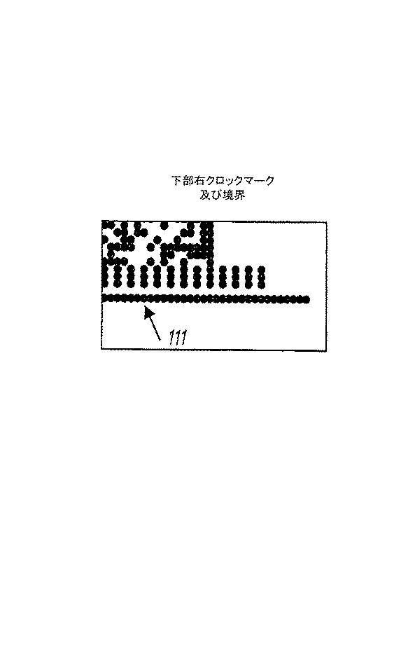
境界及びクロックマーク
図3はデータブロックを示し、図4及び5はその縁部の拡大図である。図4及び5は各データブロック内の2つの高い境界5ドット及びクロックマーク領域107及び177を示す。一方の領域はデータ領域の上方にあり、他方は下方にある。例えば上から5個の高い領域は外側の黒のドット境界線112(これはデータブロックの長さを引き伸ばす)と、白のドット分離線113(境界線が独立していることを保障する)と、3ドットの高いクロックマークの組114とを有する。クロックマークは白と黒の段の間で交互に置かれ、データブロックのどちらかの端部から8列目の黒のクロックマークから始まる。データ領域ではクロックマークのドット間では分離はない。
【0031】
クロックマークは対称的であり、符号化データが挿入されて180度回転すると、同じ関連する境界/クロックマーク領域が遭遇する。境界112,113は、データがデータ領域から読み取られる時に垂直なトラッキングを維持するように符号化データの読み取り装置により使用される。クロックマーク114はデータ領域データを読み取る時に水平なトラッキングを維持するためのものである。ドットの白の線による境界とクロックマークとの分離は、読み取り間におきるブラーリングの結果として好ましい。従って、境界は何れかの側で白を有する黒の線となり、読み取りの頻度の応答性を高める。クロックマークを白と黒とに交互に置いても、垂直の寸法ではなく水平における以外は同様な結果となる。如何なる符号化データの読み取り装置も、トラッキングに使用するのであればクロックマークと境界を配置しなければならない。次の項ではクロックマーク、境界及びデータへの道を示すターゲットについて説明する。
【0032】
ターゲット領域におけるターゲット
図7は、各データブロックにおける2つの15ドットの広いターゲット領域116、117を示し、一方のターゲット領域はデータ領域の左側にあり、他方は右側にある。ターゲット領域は、方向付けに使用される単一の列によりデータ領域から分離している。ターゲット領域116、117の目的は、クロックマーク、境界及びデータ領域への道を示すことである。各ターゲット領域は6つのターゲット118を含み、これらは符号化データの読み取り装置により簡単に見つかるように設計されている。図6は単一のターゲット120の構造を示す。各ターゲット120は15(15ドットの黒の四角形をなし、中心構造121及びランレングス符号化ターゲットナンバー122を有する。中心構造121は簡単な白の十字であり、ターゲットナンバー構成要素122は白ドットの簡単な2列であり、両方共ターゲットナンバーの各部は2ドットの長さである。ターゲットナンバーのターゲットid122は2ドットの長さである。ターゲットナンバー2のターゲットid122は4ドットの幅等である。
【0033】
図7に示すように、カードの挿入に関して回転が不変となるように、ターゲットが配置される。これは左のターゲットと右のターゲットが180度回転していること以外は同じであることを意味する。左のターゲット領域116では、ターゲット1〜6がそれぞれ上から下に配置される。右のターゲット領域116では、ターゲット1〜6がそれぞれ下から上に配置される。ターゲットナンバーidは常にデータ領域に半分最も近くにある。部分的拡大図である図7は、右のターゲットが左のターゲットと180度回転している以外は同じであることを明瞭に示している。
【0034】
図8に示すように、ターゲット124、125は中心55ドットが離れた上体でターゲット領域内に位置している。また、ターゲット1(124)の中心から上部クロックマーク領域における第1クロックマークドット126までに55ドットの距離があり、ターゲットの中心から下部クロックマーク領域(図示せず)における第1クロックマークドットまでに55ドットの距離がある。両領域における第1黒クロックマークは、ターゲットの中心の線から直接始まる(8番目のドットの位置は15ドット幅のターゲットの中心にある)。
【0035】
概略図8は、ターゲットの中心間の距離と、ターゲット1(124)から上部境界/クロックマーク領域における第1黒クロックマーク(126)の第1ドットまでの距離を示している。上部及び下部の両ターゲットからクロックマークまでに55ドットの距離があり、符号化データの両側が対称(180度回転)であるため、カードは左から右へ、また右から左へ読むことができる。読み取り方向に関わらず、データ領域からデータを抽出するためには方向を決定しなければならない。
【0036】
方向列
図9に示すように、各データブロック内に2つの1ドット広域方向列127、128があり、一方はデータ領域の左側にあり、他方は右側にある。方向列は符号化データ読み取り装置に方向情報を提供するためにある。(左のターゲットの右への)データ領域の左側は、白ドット127の単一の列である。(右のターゲットの左への)データ領域の右側は、黒ドット128の単一の列である。ターゲットは回転が不定であるため、写真が正しい方向、つまり後ろから前に挿入されると、これらの2列のドットが符号化データ読み取り装置に写真の方向を判断させる。
【0037】
符号化データ読み取り装置から見ると、ドットに劣化がないと仮定して、以下の2つの可能性がある:
・データ領域の左へのドット列が白だとすると、データ領域の右への列は黒であり、読み取り装置は写真が上記正しい方向に挿入されたことを認識する。
・データ領域の左へのドット列が黒だとすると、データ領域の右への列は白であり、読み取り装置は写真が逆に挿入されたことを認識し、データ領域は適切に回転される。読み取り装置写真から情報を正しく修復する適切な処置を取らなければならない。
【0038】
データ領域
図10に示すように、データブロックのデータ領域は各384ドットの595列、計228,480個のドットよりなる。これらのドットは分析されて解読されオリジナルデータを生成する。各ドットは単一のビットであるため、228,480ドットは228,480ビット或いは28,560バイトである。各ドットの分析を以下に示す。
【0039】
【表2】
【0040】
データ領域ドットへのオリジナルデータのマッピング
最大サイズ2,986,206バイトのオリジナルデータファイルを取り出して、それを1600dpiの写真の210データブロックにおけるデータ領域のドットにマッピングするプロセスを説明する。符号化データの読み取り装置は写真のドットからオリジナルデータを抽出するためにプロセスを逆にする。一見、ドットにデータをマッピングするのは取るに足らないように見える。バイナリデータは1と0よりなるため、カードに単に黒と白ドットを書くのは可能であるように見える。しかしこの方法では、インクが色あせ、カードが汚れやしみや引っかきにより部分的に損傷するという事実は許容されない。エラー検出の符号化なしでは、カードから取り戻したデータが正確かどうかを検出することは不可能である。符号の冗長化がなければ検出されたエラーを補正することは不可能である。マッピングステップの目的はデータの回復を高い信頼性で行い、符号化データの読み取り装置にデータを正しく読み出すことを知る能力を与えることである。
【0041】
オリジナルデータファイルをデータ領域のドットにマッピングするには、以下の4つの基本ステップがある:
・オリジナルデータを圧縮する。
【0042】
・圧縮データを冗長符号化する。
【0043】
・符号化データを決定性方法で再編成して、部分的な符号化データの損傷の影響を低減する。
【0044】
・再編成されたドットとしての符号化データを写真上のデータブロックに書き出す。
【0045】
これらの各ステップを次の節で詳細に検証する。
【0046】
オリジナルデータの圧縮
写真に記録されるデータは以下のいくつかののブロックを含む:
1)色イメージデータ
2)オーディオ注釈データ
3)イメージ処理制御スクリプト
4)位置データ(GPS受信機等から)
5)時間及び日付
6)カメラの方向
7)インクカードリッジ情報、ソフトウェアのバージョン、カメラの識別等のトラッキングデータ。
【0047】
高画質イメージのために、ソースイメージデータは2000(3000画素で各画素が3バイトであってもよい。これにより18メガバイトのデータとなり、写真の赤外線ドットに記憶できる以上のものとなる。イメージ圧縮技術を用いてほぼ無視できる程度の画質の低下を伴うが、イメージデータを約10:1の率で圧縮することができる。適切な圧縮技術としては、離散コサイン変換に基づくJPEG圧縮、ハフマン符号、JPEG2000スタンダードとして使用されるウェーブレット及びフラクタル圧縮がある。
【0048】
10:1の圧縮では、18メガバイトの高画質が1.8メガバイトの圧縮データとなる。
【0049】
オーディオ注釈データもまた、例えばMP3圧縮を用いて圧縮することができる。
【0050】
イメージ処理制御スクリプトは、スクリプトに埋め込まれたイメージ以外は一般には10キロバイト以上は消費しない。これらのイメージは圧縮すべきである。写真処理のために設計された適切なイメージ処理スクリプト言語は、本出願人により開発されてUSSN 09/113,070に開示されたヴァーク(Vark)言語である。
【0051】
リードソロモン符号を用いた冗長符号
符号化データへのデータのマッピングは、採用する冗長符号の方法に大きく依存する。バーストエラーを処理する能力及び最小の冗長化を用いてエラーを検出及び補正する能力のため、リードソロモン符号が好んで選択される。リードソロモン符号については、以下の標準的テキストの中で適切に論じられている:「リードソロモン符号とその応用」(Reed−Solomon Codes and their Applications)、S.ウィッカー(Wicker,S)、V.バーガバ(Bhargava,V)、IEEE出版、1994年、「エラーコードの詳しい説明書」(Error Coding Cookbook)、C.ロラボフ(Rorabaugh,C)、マグローヒル(McGraw−Hill)、1996年、「リードソロモンエラーの補正」(Reed−Solomon Error Correction)、H.リペン(Lyppens,H)、ドクタードッブジャーナル(Dr.Dobb’s Journal)、1997年1月号(第22巻、第1号)。
【0052】
リードソロモン符号では、異なるシンボルサイズ及び異なる冗長化のレベルを含む種々の異なるパラメータを使用することができる。以下の符号化パラメータを使用するのが好ましい:
* m=8
* t=64
m=8を有することはシンボルサイズが8ビット(1バイト)であることを意味する。これは各リードソロモン符号ブロックサイズnが255バイト(28−1シンボル)であることをも意味する。tシンボルまでの補正をするために、最終ブロックサイズにおける2tシンボルを冗長化シンボルと共に取り出さなければならない。t=64を有することは、それらにエラーがある場合、ブロックにつき64バイト(シンボル)を補正できることを意味する。従って、各255バイトのブロックは128(2×64)個の冗長化バイトを有し、残りの127バイト(K=127)はオリジナルデータを保持するために使用される。従って:
* n=255
* k=127
実用的な結果では127バイトのオリジナルデータが符号化されて255バイトブロックのリードソロモン符号データとなる。符号化された255バイトのブロックが写真に記憶され、後に符号化データ読み取り装置により再度元の127バイトに符号化されて戻される。データブロックのデータ領域の単一の列の384ドットは48バイト(384/8)を保持できる。これらの列の595は、28,560バイトを保持できる。これは112個のリードソロモンブロック(各ブロックは255バイトを有する)にもなる。完全な写真の210のデータブロックは、合計23,520個のリードソロモンブロックを保持できる(5,997,600バイト、1リードソロモンブロックにつき255バイト)。リードソロモンブロックのうち2つが情報制御のため確保されるが、残りのブロックはデータの記憶に使われる。各リードソロモンブロックは127バイトの実際のデータを保持できるため、写真に記憶できるデータ量は2,986,786バイト(23,518×127)である。オリジナルデータがこれより少ない場合、リードソロモンブロックの正確な数になるようにデータを符号化でき、その後、23,518個のブロック全てを使用するまで符号化ブロックを複写できる。図11は使用する符号化の全体の形態を示す。
【0053】
2つの制御ブロック132,133は、残りの23,518個のリードソロモンブロックを解読するために必要な同じ符号化情報を含む:
フルメッセージにおけるリードソロモンブロックの数(記憶された16ビットロー/ハイ(lo/hi))、及び
メッセージの最後のリードソロモンブロックにおけるデータバイトの数(8ビット)。
【0054】
これら2つの数を32回繰り返し(96バイト消費)、残りの31バイトを保存してゼロに設定する。次に、各制御ブロックをリードソロモン符号化し、127バイトの制御情報を255バイトのリードソロモン符号化データとする。
【0055】
制御ブロックを2度記憶して残存の可能性を上げる。また、制御ブロック内のデータの反復は、リードソロモン符号化を使用する場合特に重要である。破損していないリードソロモン符号化ブロックでは、最初の127バイトのデータは正確にオリジナルデータであり、制御ブロックの解読が失敗した時(65個以上のシンボルが破損)にオリジナルのメッセージを回復させるためにロックされる。従って、制御ブロックが解読に失敗した場合、2つの解読パラメータのための最もあり得る値を判断しようとして3バイトの組を試験することができる。回復可能であることは保障しないが、冗長化によりチャンスはより高くなる。制御ブロックの最後の159バイトが破壊されても最初の96バイトは完全に健全である。最初の96バイトは数の繰り返しの組を示す。これらの数は残りの23,518個のリードソロモンブロックにおける残りのメッセージを解読するのに賢明に使用することができる。
【0056】
リードソロモン符号化前の127バイトの各制御ブロックにおけるデータの十六進法は、図12に示す通りである。
【0057】
符号化データのスクランブル
符号化ブロックの全てがメモリに記憶されたと仮定して、最大5,997,600バイトのデータを写真に記憶させることができる(2つの制御ブロックと23,518個の情報ブロック、合計23,520個のリードソロモン符号化ブロック)。好ましくは、この段階ではデータは写真に直接には記憶されないが、255バイト全てのリードソロモンブロックはカード上で物理的に一緒になる。カードに物理的損傷を与える汚れやしみは、単一のリードソロモンブロックにおける65バイト以上を損傷させる可能性があり、これはブロックを修復不可能にするかも知れない。そのリードソロモンブロックの複写がない場合、写真全体を解読することはできない。
【0058】
この解決策として、写真には多数のバイトがあり、写真は手ごろな物理的サイズを有するという点を利用することである。データにスクランブルをかけて単一のリードソロモンブロックからのシンボルが互いに近接しないことを保証する。勿論、写真の劣化が異常な場合はリードソロモンブロックが修復不可能になるが、平均的にはデータにスクランブルをかけることによりデータははるかに頑丈になる。この選択したスクランブル手段は簡単であり、その概略が図13に示される。リードソロモンブロックからの全てのバイト0は136個一緒に置かれ、ついでバイト1が置かれる。従って、23,520個のバイト0があり、次いで23,520個のバイト1がある。写真上の各データブロックは28,560バイト記憶できる。従って、写真上の各データブロックの各リードソロモンブロックからは約4バイトある。
【0059】
このスクランブル手段では、写真上の16個全体のデータブロックへの全部の損傷は1つのリードソロモンブロックにつき64個のシンボルエラーとなる。これは、写真にその他の損傷がなければ、たとえデータの複製がなくても全体のデータは完全に修復可能であることを意味する。
【0060】
スクランブルをかけた符号化データを写真に書き込む
一度オリジナルデータをリードソロモン符号化し、複写し、スクランブルをかけると、写真に記憶されるデータは5,997,600バイトとなる。写真上の各データブロックは28,560バイトを記憶する。
【0061】
データは写真データブロックに書き出され、第1データブロックは最初の28,560バイトのスクランブルデータを有し、第2データブロックは次の28,560バイトを有する。
【0062】
図14に示すように、データブロック内でデータを列の左から右に書き出す。従って、データブロック内の最も左の列はスクランブルされたデータの28,560バイトの最初の48バイトを含み、最後の列はスクランブルされたデータの28,560バイトの最後の48バイトを含む。列内ではバイトは一度に1ビットずつ上から下に書き出され、ビット7から始まりビット0で終わる。ビットがセット(1)であれば、黒ドット(赤外線インクドット)が写真に置かれ、ビットがクリア(0)であれば、写真にはドットは置かれない。
【0063】
例えば、写真に記憶される23,520リードソロモン符号化ブロックにスクランブルをかけることにより、1組5,997,600バイトのデータを生成することができる。最初の28,560バイトのデータが最初のデータブロックに書き出される。最初の28,560バイトの最初の48バイトがデータブロックの最初の列に書き出され、次の48バイトが次の列に書き出され、以下同様に続く。28,560バイトの最初の2バイトが16進法D3 5Fであると仮定する。最初の2バイトがデータブロックの列0に記憶される。バイト0のビット7が最初に記憶され、次いでビット6が記憶され、以下同様に続く。バイト1のビット7がバイト1のビット0に記憶される。各「1」が黒ドットとして記憶され、各「0」が白ドットとして記憶され、これら2バイトが以下のドット組として写真に示される:
・D3(1101 0011)は黒、黒、白、黒、白、白、黒、黒となり、
・5F(0101 1111)は白、黒、白、黒、黒、黒、黒、黒となる。
【0064】
符号化されたイメージデータはインクジェットプリンタに送られ、赤外線インクジェットノズルを駆動し、イメージデータを使用して、シアン、マゼンタ及び黄色のノズルを駆動し、プリンタのプリントヘッドを介して印刷媒体を駆動する。
【0065】
カメラシステムにより得られたイメージはそのイメージを複製するのに必要なデータを有する写真イメージとして利用できる。写真のコピーが必要なければネガを別個に設ける必要はなく、損傷に関係なくイメージを複製でき、そのイメージをデジタルフォーマットで利用できる。これは目的は何であれ、コンピュータシステム内にスキャンにより取り込んだり通信ネットワークを通じて転送することもできる。
【0066】
他のデータは、日付や写真を写した場所や、例えばカメラシステムにGPS設備が組み込まれている場合、写真露光の詳細、この情報を視覚的データ、デジタルデータ或いはオーディオデータとして記憶すべきか否かなどを、イメージデータと共に記録してもよい。本出願人による同時係属出願PCT/AU01/_____(整理番号 ART83)等に開示されるように、オーディオ設備が含まれている場合、写真家による会話などのオーディオ情報もイメージと共に記録してもよい。
【0067】
アートカード(Artcard)フォーマットと呼ばれる別のフォーマットがUSSN 09/113,070 及びUSSN 09/112,785に開示されており、上記オルタナティブアートカード(alternative Artcard)フォーマットの代わりに同様に使用しても良い。アートカード(Artcard)フォーマットでは、今回の場合、データ領域の前縁及び後縁にターゲットとして、及びデータ領域に含まれるデータの解読を助けるべく上及び下にそって境界及びクロックマークを特定する印として、印刷される余白により囲まれた写真上の赤外線インクで、データの連続する領域が印刷媒体に印刷される。読み取り時にカードの方向が水平より1度以上回転しないことを確認し、カードが最初に前或いは後ろ向きのどちらで挿入されたかを検出するために、ターゲットが使用される。そうしなければデータの読み取りは信頼性はない。
【0068】
以上の説明は、本発明の特定の実施態様に限定されない。本発明では、この発明の幾つか或いは全ての利点を習得すれば、変更や変形を成し得ることは明らかである。例えば、適切にプログラムされたデジタルデータ処理システムにおいて、本発明をハードウェア或いはソフトウェアの何れでも実現でき、両者の場合共に当業者により容易に達成されるであろう。従って、従属項の目的は、本発明の真の思想及び範囲内に入る変更及び変形を網羅することである。
【図面の簡単な説明】
【図1】
カード或いは写真のデータ面を示す図である。
【図2】
単一のデータブロックのレイアウトを概略的に示す図である。
【図3】
単一のデータブロックを示す図である。
【図4】
図3のデータブロックの部分拡大図である。
【図5】
図3のデータブロックの部分拡大図である。
【図6】
単一のターゲット構造を示す図である。
【図7】
データブロックのターゲット構造を示す図である。
【図8】
データ領域の境界クロック領域に対するターゲットの位置関係を示す図である。
【図9】
データブロックの方向コラムを示す図である。
【図10】
データブロックの点の配列を示す図である。
【図11】
リードソロモン符号のためのデータ構造を概略的に示す図である。
【図12】
リードソロモン符号前の制御ブロックデータの構造を16進法で示す図である。
【図13】
リードソロモン符号化プロセスを示す図である。
【図14】
データブロック内の符号化データのレイアウトを示す図である。
【符号の説明】
101 データ面
102 活性領域
103 境界領域
104 データブロック
106 間隙[0001]
TECHNICAL FIELD OF THE INVENTION
The present invention relates to a data processing method and apparatus, and more particularly to a data encoding method and apparatus for storing data in an error-tolerant image from a photograph using infrared ink. This data is original image data obtained from the camera system.
[0002]
(Co-pending application)
Various methods, systems and devices related to the present invention are disclosed in the following co-pending applications filed by the present applicant concurrently with the present invention.
[0003]
[Table 1]
[0004]
Various methods, systems and apparatus related to the present invention are disclosed in the following co-pending application filed July 10, 1998 by the present applicant concurrently with the present invention.
[0005]
USSN $ 09 / 113,070
USSN 09 / 112,785
The disclosures of these co-pending applications are incorporated herein by reference.
[0006]
Various methods, systems and apparatus related to the present invention are disclosed in the following co-pending application filed on June 30, 2000 by the present applicant concurrently with the present invention.
[0007]
PCT / AU00 / 00743, PCT / AU00 / 00744, PCT / AU00 / 00745, PCT / AU00 / 00746, PCT / AU00 / 00747 and PCT / AU00 / 00748.
The disclosures of these co-pending applications are incorporated herein by reference.
[0008]
BACKGROUND OF THE INVENTION
As noted by the applicant in the pending applications USSN 09 / 113,070 and USSN 09 / 112,785, it allows large amounts of computer data to be stored on simple print media such as cards. There is a general need for a print media scanning system that allows for a high degree of damage when read by a scanning device. For example, the form of distribution can suffer from a large amount of data corruption errors when scanning a surface with a scanning device. Errors include the following:
1. A dead pixel error that occurs in the reading of a card surface with a linear CCD with a pixel reader with a line defect, thus producing the same value at every point on the line.
2. Preferably, the system employed can tolerate errors where the text is written by the owner on the surface of the card. Ideally, such errors are tolerated by the scanning system that scans the card.
3. Various data errors can occur on the surface of the card. Any damage or defect should be tolerated by the system that determines the information stored on the card surface.
4. There is some "play" when inserting a card into a card reader. This play may include some rotation of the card as it is read by the card reader.
5. Further, it is assumed that the card reader is driven by an electric motor past a linear image sensor such as a CCD. Electric motors can be subject to some variation, which leads to variations in the transmission of data across the surface of the CCD. Motor fluctuation errors should also be tolerated by the method of data encoding on the surface of the card.
6. The scanner on the card surface is subject to various device variations, and the intensity of individual pixels is changed. Variations in the intensity of the reader should also be tolerated by the system or method performed on the data contained on the card surface.
[0009]
Ideally, any scanning system should maintain its accuracy in the event of errors due to the above factors.
[0010]
In US patent applications US Ser. No. 09 / 113,070 and US Ser. No. 09 / 112,785, applicants prefer to print data in a coding error tolerant form behind a photograph, preferably using black ink on a white background. And an apparatus. The data is indicative of a photograph in digital image file format and / or data consisting of a computer program script that reproduces the image or applies certain effects to the image. A programming language called VARK script was invented for this purpose, designed as a portable, stand-alone device.
[0011]
[Means for Solving the Problems]
The present invention seeks to provide another method of encoding and storing data by printing digital data corresponding to the image in or on a coding error tolerant digital form on or with the image using infrared ink. The image and data are stored on a print medium using the inkjet printing system disclosed by the present applicant.
[0012]
It is an object of the present invention to provide a method for printing digital data on a photograph, comprising the following steps:
a) receiving image data corresponding to the image;
b) converting the image data into a coding error tolerant digital form;
c) printing the error tolerant digital form of the image data with an ink that is not visible on the surface of a print medium using an inkjet printing process, while simultaneously viewing the image data as a photographic image representing the image data. And printing in a human-readable form.
[0013]
Preferably, the step of encoding includes a step of compressing the image data and a step of processing using the Reed-Solomon algorithm.
[0014]
The invisible ink may be an infrared absorbing ink that hardly absorbs the visible spectrum.
[0015]
It is a further object of the present invention to provide an apparatus for printing coding error tolerant digital data on a photograph with infrared ink, the apparatus comprising:
a) a camera system for projecting the image and outputting said image in digital format;
b) means for processing the digital format of the image into an error-tolerant encoded digital form;
c) means for printing the image and the error tolerant coded digital form using an inkjet printing process;
Wherein the error tolerant encoded digital form is printed using infrared ink.
[0016]
Preferably, the means for printing uses a page width printhead using an ink jet structure in which a print roll provides a print medium. Page-width printheads are disclosed, for example, in the following applications by the applicant: PCT / AU00 / 00743, PCT / AU00 / 00744, PCT / AU00 / 00745, PCT / AU00 / 00746, PCT / AU00 / 00747 and PCT / AU00 / 00748. Print rolls for supplying print media are disclosed in Applicants' Artcam applications USSN 09 / 113,070 and USSN 09 / 112,785.
[0017]
According to a preferred form of the invention, a standard size of about 102 (152 mm (4 ″ × 6 ″)) compared to a conventional 85 mm × 55 mm (substantially the size of a credit card) formatted data encoding card. The information is printed on the photo.The increased size of the storage medium reduces the amount of data stored in the photo compared to the conventional format, while using the same or the same data encoding technology. 3 to 4 times more.
[0018]
BEST MODE FOR CARRYING OUT THE INVENTION
The invention includes an inkjet printing system having at least four inkjet printing nozzles per dot, preferably printed on a page width printhead. The four inks are cyan, magenta, yellow, and infrared (IR) inks for printing data with the color image in a color-encoding tolerant form for printing the color image. Ink jet printheads that can print using four inks are described in co-pending applications PCT / AU00 / 00743, PCT / AU00 / 00744, PCT / AU00 / 00745, PCT / AU00 / 00746, PCT / AU00 / 00747, and PCT / AU00 / 00747. PCT / AU00 / 00748.
[0019]
The infrared inks used in the present invention are co-pending Australian applicants of the following Australian Provisional Applications: PQ9412 and PQ9376 filed on August 14, 2000, and PQ9509 filed on August 18, 2000. , PQ9571 and PQ9561 filed on August 21, 2000.
[0020]
According to the invention, the image is taken by a digital camera area image sensor and the scanned image is read out as data. This data is processed by the processing unit and converted to an encoded form using an error-tolerant encoding method such as using the Reed-Solomon format. The data thus encoded is supplied to a printer means for printing the encoded data using an inkjet printing process. Apparatuses that perform these functions and techniques that can be used to encode image data are disclosed in co-pending USSN 09 / 113,070 and USSN 09 / 112,785 filed by the present applicant. The means are disclosed in PCT / AU00 / 00743, PCT / AU00 / 00744, PCT / AU00 / 00745, PCT / AU00 / 00746, PCT / AU00 / 00747 and PCT / AU00 / 00748. These contents are incorporated herein by reference. These techniques are described in the art card (Altcard), alternative art card (alternative @ Artcard) or dot card (Dotcard) format. In these applications, an 85 mm × 55 mm card in an 80 mm × 50 mm active data area is printed using black ink on a white background. In this method, 967 kilobytes of data are encoded as error tolerant as 1.89 megabytes of data using 15,876,000 print dots.
[0021]
Encoded data format
While other encoded data formats are possible, one encoded data format is described with many preferred features.
[0022]
Overview of encoded data
The encoded data can be used to restore the written image or to provide a digital format for operation in applications such as transfer to a digital communications network or image processing in a computer.
[0023]
The technology of the encoded data can be independent of the printing resolution. The concept of storing data such as dots on a print medium means that if more dots can be placed in the same space (by increasing the resolution), these dots can represent more data. In the preferred embodiment, the use of 1600 dpi for 102 mm x 152 mm (4 "x 6") is considered a sample photo, but equivalent layout and data for other photo sizes and / or other print resolutions. Determining the size is easy. For example, applicant's inkjet printing camera system can produce a panoramic print that is twice as long as a normal sized photo, which would record twice as much data, thus eliminating duplication of image data. Increase. Regardless of the print resolution, the reading technique remains the same. After accounting for all decoding and other overhead, the encoded data format can store 3-4 megabytes of data for a 4 "x6" print size at print resolutions up to 1600 dpi. If the printing resolution is 1600 dpi or more, further encoded data can be stored.
[0024]
Encoded data format
Thus, the structure of the photographic data is specifically designed to assist in data recovery. This section describes the photo data format. This format is described in the Applicant's USSN 09 / 113,070 and USSN 09 / 112,785 as an alternative ArtCard format.
[0025]
Dot
The dots printed on the photographs are infrared inks or color images. Therefore, “data dots” are physically different from “non-data dots”. When a photograph is illuminated with an infrared source having spectral characteristics of complementary colors to the absorption characteristics of the infrared ink, the data appears as a "black" monochrome display with "white" dots. The black dots correspond to the dots, the infrared ink has absorbed infrared radiation, and the "white" dot is a color that reflects the infrared radiation that is not printed or substantially attenuated or only partially attenuated. Corresponds to the area of the image. Hereinafter, the terms black and white as defined above are used with reference to infrared ink dots for recording data.
[0026]
In the description of this embodiment, the term dot means a dot (or infrared ink) physically printed on a photograph. When a coded data reader scans coded data, it must extract dots with at least twice the printing resolution to satisfy Nyquist's theorem. The term pixel means a sample value from a device for reading encoded data. For example, if a 1600 dpi dot is scanned at 4800 dpi, there are three pixels in each dimension of the dot, ie, there are nine pixels in each dot. The sampling step will be described later.
[0027]
Referring to FIG. 1, there is shown a
[0028]
Data block
Referring now to FIG. 2, a
[0029]
Each data block 107 has a size of 627 (394 dots), of which the central area of 594 (384 dots is the
[0030]
Boundary and clock mark
FIG. 3 shows a data block, and FIGS. 4 and 5 are enlarged views of the edge. FIGS. 4 and 5 show two high boundary 5 dot and
[0031]
The clock marks are symmetric, and when the encoded data is inserted and rotated 180 degrees, the same associated boundary / clock mark area is encountered. The
[0032]
Target in target area
FIG. 7 shows two 15 dot
[0033]
As shown in FIG. 7, the targets are arranged such that the rotation is invariable with respect to the insertion of the card. This means that the left and right targets are the same except that they are rotated 180 degrees. In the
[0034]
As shown in FIG. 8, the
[0035]
Figure 8 shows the distance between the centers of the targets and the distance from target 1 (124) to the first dot of the first black clock mark (126) in the upper boundary / clock mark area. The card can be read from left to right and right to left, because there is a distance of 55 dots from both the upper and lower targets to the clock mark and the encoded data is symmetrical (180 degree rotation) on both sides. . Regardless of the reading direction, the direction must be determined in order to extract data from the data area.
[0036]
Direction column
As shown in FIG. 9, there are two one-dot
[0037]
From the point of view of the encoded data reader, there are two possibilities, assuming that the dots are not degraded:
If the dot row to the left of the data area is white, the row to the right of the data area is black, and the reader recognizes that the picture has been inserted in the correct direction.
If the dot row to the left of the data area is black, the row to the right of the data area is white and the reader recognizes that the picture has been inserted backwards and the data area is rotated appropriately. Appropriate measures must be taken to correctly recover the information from the reader photo.
[0038]
Data area
As shown in FIG. 10, the data area of the data block is composed of a total of 228,480 dots in 595 columns of 384 dots. These dots are analyzed and decoded to produce the original data. Since each dot is a single bit, 228,480 dots are 228,480 bits or 28,560 bytes. The analysis of each dot is shown below.
[0039]
[Table 2]
[0040]
Mapping of original data to data area dots
The process of taking an original data file with a maximum size of 2,986,206 bytes and mapping it to dots in the data area in 210 data blocks of a 1600 dpi photo is described. The encoded data reader reverses the process to extract the original data from the photographic dots. At first glance, mapping data to dots looks trivial. Since binary data consists of ones and zeros, it seems possible to simply write black and white dots on the card. However, this method does not tolerate the fact that the ink fades and the card is partially damaged by dirt, stains or scratches. Without error detection encoding, it is not possible to detect whether the data retrieved from the card is accurate. Without code redundancy, it is impossible to correct the detected error. The purpose of the mapping step is to provide reliable data recovery and to provide the encoded data reader with the ability to know that the data is being read correctly.
[0041]
There are four basic steps to map the original data file to the dots in the data area:
-Compress the original data.
[0042]
-Redundantly encode the compressed data.
[0043]
Reorganize the coded data in a deterministic manner to reduce the effects of partial coded data damage.
[0044]
Write out the coded data as rearranged dots into data blocks on the picture.
[0045]
Each of these steps will be examined in detail in the following sections.
[0046]
Compression of original data
The data recorded in the photo contains several blocks:
1) Color image data
2) Audio annotation data
3) Image processing control script
4) Position data (from GPS receiver etc.)
5) Time and date
6) Camera direction
7) Tracking data such as ink cartridge information, software version, and camera identification.
[0047]
For high quality images, the source image data may be 2000 (3000 pixels and each pixel may be 3 bytes. This results in 18 megabytes of data, more than can be stored in the infrared dots of a photo. Techniques can be used to compress image data at a rate of about 10: 1, albeit with almost negligible image quality degradation, suitable compression techniques include JPEG compression based on discrete cosine transform, Huffman code, There are wavelet and fractal compression used as JPEG2000 standard.
[0048]
With 10: 1 compression, 18 megabytes of high image quality is converted to 1.8 megabytes of compressed data.
[0049]
Audio annotation data can also be compressed using, for example, MP3 compression.
[0050]
The image processing control script generally does not consume more than 10 kilobytes except for the image embedded in the script. These images should be compressed. A suitable image processing scripting language designed for photo processing is the Vark language developed by the applicant and disclosed in US Ser. No. 09 / 113,070.
[0051]
Redundant code using Reed-Solomon code
The mapping of the data to the coded data largely depends on the adopted redundant coding method. Reed-Solomon codes are preferred because of their ability to handle burst errors and to detect and correct errors with minimal redundancy. Reed-Solomon codes are properly discussed in the following standard texts: "Reed-Solomon Codes and Applications", Reed-Solomon Codes and their Applications. Wicker, S .; Bhargava, V, IEEE Publishing, 1994, "Detailed Description of Error Codes" (Error @ Coding @ Cookbook), C.I. Rorabough, C, McGraw-Hill, 1996, "Reed-Solomon Error Correction", H.E. Lippens (H), Dr. Dobb's @ Journal, January 1997 (Vol. 22, No. 1).
[0052]
A variety of different parameters can be used in Reed-Solomon codes, including different symbol sizes and different levels of redundancy. Preferably, the following coding parameters are used:
* M = 8
* T = 64
Having m = 8 means that the symbol size is 8 bits (1 byte). This is because each Reed-Solomon code block size n is 255 bytes (28(-1 symbol). In order to correct up to t symbols, 2t symbols in the final block size must be extracted together with the redundancy symbols. Having t = 64 means that 64 bytes (symbols) per block can be corrected if they have errors. Thus, each 255 byte block has 128 (2 × 64) redundant bytes, and the remaining 127 bytes (K = 127) are used to hold the original data. Therefore:
* N = 255
* K = 127
In practical results, the original data of 127 bytes is encoded into Reed-Solomon encoded data of a 255-byte block. The encoded 255 byte block is stored in the photograph and later encoded back to the original 127 bytes by the encoded data reader. A single column of 384 dots in the data area of a data block can hold 48 bytes (384/8). 595 of these columns can hold 28,560 bytes. This also amounts to 112 Reed-Solomon blocks (each block has 255 bytes). The 210 data blocks of the complete picture can hold a total of 23,520 Reed-Solomon blocks (5,997,600 bytes, 255 bytes per Reed-Solomon block). Two of the Reed-Solomon blocks are reserved for information control, while the remaining blocks are used for data storage. Since each Reed-Solomon block can hold 127 bytes of actual data, the amount of data that can be stored in a photograph is 2,986,786 bytes (23,518 × 127). If the original data is less than this, the data can be encoded to the exact number of Reed-Solomon blocks, and then the encoded block can be copied until all 23,518 blocks are used. FIG. 11 shows the overall form of encoding used.
[0053]
The two control blocks 132,133 contain the same coding information needed to decrypt the remaining 23,518 Reed-Solomon blocks:
The number of Reed-Solomon blocks in the full message (stored 16-bit low / high (lo / hi)), and
Number of data bytes in the last Reed-Solomon block of the message (8 bits).
[0054]
These two numbers are repeated 32 times (96 bytes consumed), the remaining 31 bytes are saved and set to zero. Next, each control block is Reed-Solomon encoded, and the 127-byte control information is converted into 255-byte Reed-Solomon encoded data.
[0055]
The control block is stored twice to increase the possibility of surviving. Also, repetition of the data in the control block is especially important when using Reed-Solomon coding. In a non-corrupted Reed-Solomon coded block, the first 127 bytes of data are exactly the original data, to recover the original message when the control block decoding fails (more than 65 symbols are corrupted). Locked to. Thus, if the control block fails to decrypt, the set of three bytes can be tested in an attempt to determine the most likely value for the two decryption parameters. It does not guarantee that it can be recovered, but the redundancy increases the chance. Even if the last 159 bytes of the control block are corrupted, the first 96 bytes are completely sound. The first 96 bytes indicate a repeating set of numbers. These numbers can be used wisely to decrypt the remaining messages in the remaining 23,518 Reed-Solomon blocks.
[0056]
The hexadecimal representation of data in each 127-byte control block before Reed-Solomon encoding is as shown in FIG.
[0057]
Scramble encoded data
Assuming that all of the coded blocks have been stored in memory, a maximum of 5,997,600 bytes of data can be stored in the photo (two control blocks and 23,518 information blocks, 23,520 total) Reed-Solomon coding blocks). Preferably, at this stage the data is not stored directly in the photo, but all 255 bytes of the Reed-Solomon block are physically combined on the card. Dirt and stains that physically damage the card can damage more than 65 bytes in a single Reed-Solomon block, which may render the block irreparable. Without a copy of the Reed-Solomon block, the entire photo cannot be decrypted.
[0058]
The solution is to take advantage of the fact that a photo has a large number of bytes and that the photo has a reasonable physical size. The data is scrambled to ensure that symbols from a single Reed-Solomon block are not close to each other. Of course, if the photo deteriorates abnormally, the Reed-Solomon block becomes unrecoverable, but on average the data becomes much more robust by scrambling the data. This selected scrambling means is simple and is shown schematically in FIG. All bytes 0 from the Reed-Solomon block are put together 136, followed by byte 1. Thus, there are 23,520 bytes 0, followed by 23,520 bytes 1. Each data block on the photo can store 28,560 bytes. Therefore, there are approximately 4 bytes from each Reed-Solomon block of each data block on the photograph.
[0059]
With this scrambling means, any damage to all 16 data blocks on the photo will result in 64 symbol errors per Reed-Solomon block. This means that if the photo is not otherwise damaged, the entire data is completely recoverable, even without a duplicate of the data.
[0060]
Write scrambled encoded data to photos
Once the original data is Reed-Solomon encoded, copied, and scrambled, the data stored in the photo will be 5,997,600 bytes. Each data block on the photo stores 28,560 bytes.
[0061]
The data is written into a photographic data block, with the first data block having the first 28,560 bytes of scrambled data and the second data block having the next 28,560 bytes.
[0062]
As shown in FIG. 14, data is written from left to right of a column in a data block. Thus, the leftmost column in the data block contains the first 48 bytes of the 28,560 bytes of scrambled data, and the last column contains the last 48 bytes of the 28,560 bytes of scrambled data. Within a column, bytes are written one bit at a time, from top to bottom, starting at bit 7 and ending at bit 0. If the bit is set (1), a black dot (infrared ink dot) is placed on the photo; if the bit is clear (0), no dot is placed on the photo.
[0063]
For example, a set of 5,997,600 bytes of data can be generated by scrambling a 23,520 Reed-Solomon encoded block stored in a photograph. The first 28,560 bytes of data are written to the first data block. The first 48 bytes of the first 28,560 bytes are written to the first column of the data block, the next 48 bytes are written to the next column, and so on. Assume that the first two bytes of 28,560 bytes are hexadecimal D3 @ 5F. The first two bytes are stored in column 0 of the data block. Bit 7 of byte 0 is stored first, then bit 6 is stored, and so on. Bit 7 of byte 1 is stored in bit 0 of byte 1. Each "1" is stored as a black dot, each "0" is stored as a white dot, and these two bytes are shown in the photograph as the following dot set:
D3 (1101 0011) is black, black, white, black, white, white, black, black,
5F (0101 1111) is white, black, white, black, black, black, black, and black.
[0064]
The encoded image data is sent to an inkjet printer, which drives the infrared inkjet nozzles, uses the image data to drive the cyan, magenta, and yellow nozzles and drives the print media through the printhead of the printer. .
[0065]
The image obtained by the camera system can be used as a photographic image with the data necessary to duplicate the image. If you don't need a copy of the photo, you don't need a separate negative, you can duplicate the image regardless of damage and use the image in digital format. It can be captured by a computer system or transferred over a communication network for any purpose.
[0066]
Other data includes the date and location of the photograph, and details of the photographic exposure, for example, if the camera system has GPS equipment, whether this information should be stored as visual, digital, or audio data. May be recorded together with the image data. As disclosed in co-pending application PCT / AU01 / ___________________________________________________ by applicant of the present application (reference number ART83), if audio equipment is included, audio information, such as conversations by photographers, may be recorded together with the image. .
[0067]
Another format called the Artcard format is disclosed in USSN 09 / 113,070 and USSN 09 / 112,785, which may be used instead of the alternative Artcard format as well. . In the Artcard format, in this case, marks are used to identify boundaries and clock marks as targets at the leading and trailing edges of the data area and along the top and bottom to assist in decoding the data contained in the data area. A continuous area of data is printed on a print medium with infrared ink on a photograph surrounded by a margin to be printed. The target is used to ensure that the orientation of the card does not rotate more than one degree from horizontal when reading, and to detect whether the card was first inserted forward or backward. Otherwise, reading the data is not reliable.
[0068]
The description is not limited to a specific embodiment of this invention. Obviously, modifications and variations can be made in the present invention, provided that they learn some or all of the advantages of the invention. For example, in a suitably programmed digital data processing system, the present invention may be implemented in either hardware or software, and both will be readily accomplished by those skilled in the art. Therefore, the purpose of the dependent claims is to cover modifications and variations that fall within the true spirit and scope of the invention.
[Brief description of the drawings]
FIG.
It is a figure showing the data side of a card or a photograph.
FIG. 2
FIG. 3 is a diagram schematically illustrating a layout of a single data block.
FIG. 3
FIG. 3 is a diagram illustrating a single data block.
FIG. 4
FIG. 4 is a partially enlarged view of the data block in FIG. 3.
FIG. 5
FIG. 4 is a partially enlarged view of the data block in FIG. 3.
FIG. 6
FIG. 4 illustrates a single target structure.
FIG. 7
FIG. 3 is a diagram illustrating a target structure of a data block.
FIG. 8
FIG. 3 is a diagram illustrating a positional relationship of a target with respect to a boundary clock area of a data area.
FIG. 9
FIG. 4 is a diagram showing a direction column of a data block.
FIG. 10
FIG. 4 is a diagram showing an array of points in a data block.
FIG. 11
FIG. 3 is a diagram schematically illustrating a data structure for a Reed-Solomon code.
FIG.
FIG. 3 is a diagram illustrating a structure of control block data before a Reed-Solomon code in hexadecimal notation.
FIG. 13
FIG. 4 illustrates a Reed-Solomon encoding process.
FIG. 14
FIG. 3 is a diagram illustrating a layout of encoded data in a data block.
[Explanation of symbols]
101 Data side
102 active area
103 border area
104 data block
106 ° gap
Claims (7)
a)イメージに対応するイメージデータを受信するステップと;
b)前記イメージデータを符号化された誤り許容デジタルフォームに変換するステップと;
c)インクジェット印刷プロセスを用いて前記イメージデータの前記誤り許容デジタルフォームを印刷媒体の表面に見えないインクで印刷し、同時に、前記イメージデータを表す写真イメージとして前記イメージデータを同じ表面に見えるように、且つ人間が読める形態で印刷するステップと;
を含む、写真にデジタルデータを印刷する方法。A method of printing digital data on a photo,
a) receiving image data corresponding to the image;
b) converting the image data into an encoded error tolerant digital form;
c) printing the error tolerant digital form of the image data with an ink that is not visible on the surface of a print medium using an inkjet printing process, while simultaneously viewing the image data as a photographic image representing the image data. Printing in human readable form;
How to print digital data on photos, including:
a)イメージを映し、前記イメージをデジタルフォーマットで出力するカメラシステムと;
b)前記イメージの前記デジタルフォーマットを誤り許容符号化デジタルフォームに処理する手段と;
c)インクジェット印刷プロセスを用いて前記イメージ及び前記誤り許容符号化デジタルフォームを印刷する手段と;
を含み、前記誤り許容符号化デジタルフォームは赤外線インクを用いて印刷される、写真に符号化誤り許容デジタルデータを赤外線インクで印刷する装置。A device that prints encoding error-permitted digital data on a photograph with infrared ink,
a) a camera system for projecting the image and outputting said image in digital format;
b) means for processing the digital format of the image into an error-tolerant encoded digital form;
c) means for printing the image and the error tolerant coded digital form using an inkjet printing process;
An apparatus for printing coded error tolerant digital data on a photograph with infrared ink, wherein the error tolerant encoded digital form is printed using infrared ink.
Applications Claiming Priority (2)
| Application Number | Priority Date | Filing Date | Title |
|---|---|---|---|
| US09/693,471 US6496654B1 (en) | 2000-10-20 | 2000-10-20 | Method and apparatus for fault tolerant data storage on photographs |
| PCT/AU2001/001317 WO2002034525A1 (en) | 2000-10-20 | 2001-10-19 | Method and apparatus for fault tolerant data storage on photographs |
Publications (2)
| Publication Number | Publication Date |
|---|---|
| JP2004511368A true JP2004511368A (en) | 2004-04-15 |
| JP3937328B2 JP3937328B2 (en) | 2007-06-27 |
Family
ID=24784790
Family Applications (1)
| Application Number | Title | Priority Date | Filing Date |
|---|---|---|---|
| JP2002537547A Expired - Fee Related JP3937328B2 (en) | 2000-10-20 | 2001-10-19 | Method and apparatus for error tolerance data storage of photographs |
Country Status (12)
| Country | Link |
|---|---|
| US (2) | US6496654B1 (en) |
| EP (1) | EP1333979B1 (en) |
| JP (1) | JP3937328B2 (en) |
| KR (1) | KR100505267B1 (en) |
| CN (1) | CN1222412C (en) |
| AT (1) | ATE430657T1 (en) |
| AU (2) | AU9529001A (en) |
| DE (1) | DE60138639D1 (en) |
| IL (1) | IL155491A0 (en) |
| SG (1) | SG125986A1 (en) |
| WO (1) | WO2002034525A1 (en) |
| ZA (1) | ZA200303182B (en) |
Families Citing this family (20)
| Publication number | Priority date | Publication date | Assignee | Title |
|---|---|---|---|---|
| US6786420B1 (en) | 1997-07-15 | 2004-09-07 | Silverbrook Research Pty. Ltd. | Data distribution mechanism in the form of ink dots on cards |
| US6618117B2 (en) | 1997-07-12 | 2003-09-09 | Silverbrook Research Pty Ltd | Image sensing apparatus including a microcontroller |
| US20040119829A1 (en) | 1997-07-15 | 2004-06-24 | Silverbrook Research Pty Ltd | Printhead assembly for a print on demand digital camera system |
| US6624848B1 (en) | 1997-07-15 | 2003-09-23 | Silverbrook Research Pty Ltd | Cascading image modification using multiple digital cameras incorporating image processing |
| US6690419B1 (en) | 1997-07-15 | 2004-02-10 | Silverbrook Research Pty Ltd | Utilising eye detection methods for image processing in a digital image camera |
| US7110024B1 (en) | 1997-07-15 | 2006-09-19 | Silverbrook Research Pty Ltd | Digital camera system having motion deblurring means |
| US6879341B1 (en) | 1997-07-15 | 2005-04-12 | Silverbrook Research Pty Ltd | Digital camera system containing a VLIW vector processor |
| AUPP702098A0 (en) | 1998-11-09 | 1998-12-03 | Silverbrook Research Pty Ltd | Image creation method and apparatus (ART73) |
| AUPQ439299A0 (en) | 1999-12-01 | 1999-12-23 | Silverbrook Research Pty Ltd | Interface system |
| AUPQ056099A0 (en) | 1999-05-25 | 1999-06-17 | Silverbrook Research Pty Ltd | A method and apparatus (pprint01) |
| US6859225B1 (en) | 2000-10-20 | 2005-02-22 | Silverbrook Research Pty Ltd | Method and apparatus for fault tolerant data storage on photographs |
| US6924835B1 (en) * | 2000-10-20 | 2005-08-02 | Silverbrook Research Pty Ltd | Method and apparatus for fault tolerant data storage on photographs |
| US6689518B1 (en) * | 2002-11-20 | 2004-02-10 | Eastman Kodak Company | Photographic display elements comprising stable IR dye compositions for invisible marking |
| US7991432B2 (en) * | 2003-04-07 | 2011-08-02 | Silverbrook Research Pty Ltd | Method of printing a voucher based on geographical location |
| US7278570B2 (en) * | 2003-09-19 | 2007-10-09 | First Data Corporation | Financial presentation instruments with integrated holder and methods for use |
| DE602004026924D1 (en) * | 2004-01-21 | 2010-06-10 | Silverbrook Res Pty Ltd | INK JET PRINTER SYSTEM WITH REMOVABLE CARTRIDGE |
| CN101407133B (en) * | 2004-01-21 | 2012-10-10 | 西尔弗布鲁克研究有限公司 | Ink cartridge of ink-jet printer |
| CN100498829C (en) * | 2004-07-12 | 2009-06-10 | 凌阳科技股份有限公司 | Media with index data and system for reading the media with index data |
| US7284921B2 (en) | 2005-05-09 | 2007-10-23 | Silverbrook Research Pty Ltd | Mobile device with first and second optical pathways |
| US7885878B2 (en) | 2008-05-28 | 2011-02-08 | First Data Corporation | Systems and methods of payment account activation |
Family Cites Families (24)
| Publication number | Priority date | Publication date | Assignee | Title |
|---|---|---|---|---|
| JPS60192668A (en) | 1984-03-14 | 1985-10-01 | Toshiba Corp | Image former |
| US5042079A (en) | 1988-08-12 | 1991-08-20 | Casio Computer Co., Ltd. | Method of recording/reproducing data of mesh pattern, and apparatus therefor |
| JPH0236825U (en) | 1988-09-02 | 1990-03-09 | ||
| US4937676A (en) | 1989-02-10 | 1990-06-26 | Polariod Corporation | Electronic camera system with detachable printer |
| US5493409A (en) | 1990-11-29 | 1996-02-20 | Minolta Camera Kabushiki Kaisha | Still video camera having a printer capable of printing a photographed image in a plurality of printing modes |
| CA2035670A1 (en) | 1991-02-04 | 1992-08-05 | William H. Lustig | Kwik-krib/super forms |
| JPH0662309A (en) | 1992-08-10 | 1994-03-04 | Olympus Optical Co Ltd | Film picture reproducing device |
| DE69332814T2 (en) | 1992-09-28 | 2003-12-18 | Olympus Optical Co | Information display system for optical point code reading from a recording medium |
| JP3244371B2 (en) | 1993-12-22 | 2002-01-07 | オリンパス光学工業株式会社 | Audio information processing system and audio information processing method |
| JPH0981711A (en) * | 1995-09-20 | 1997-03-28 | Olympus Optical Co Ltd | Information recording medium, information reproduction system, and information recording the system |
| US5726693A (en) | 1996-07-22 | 1998-03-10 | Eastman Kodak Company | Ink printing apparatus using ink surfactants |
| US5878292A (en) | 1996-08-29 | 1999-03-02 | Eastman Kodak Company | Image-audio print, method of making and player for using |
| AUPO939997A0 (en) | 1997-09-23 | 1997-10-16 | Silverbrook Research Pty Ltd | Data processing method and apparatus (ART61) |
| US6459495B1 (en) | 1997-07-15 | 2002-10-01 | Silverbrook Research Pty Ltd | Dot center tracking in optical storage systems using ink dots |
| US6476863B1 (en) | 1997-07-15 | 2002-11-05 | Silverbrook Research Pty Ltd | Image transformation means including user interface |
| AUPO939597A0 (en) * | 1997-09-23 | 1997-10-16 | Silverbrook Research Pty Ltd | Data processing method and apparatus (ART4) |
| US5996893A (en) * | 1997-10-28 | 1999-12-07 | Eastman Kodak Company | Method and apparatus for visually identifying an area on a photograph or image where digital data is stored |
| US6191406B1 (en) | 1998-07-24 | 2001-02-20 | Eastman Kodak Company | Data reader and reader system having visible centerless targeting |
| AU5373600A (en) | 2000-06-30 | 2002-01-14 | Silverbrook Res Pty Ltd | An ejector mechanism for a print engine |
| US6425700B1 (en) | 2000-06-30 | 2002-07-30 | Silverbrook Research Pty Ltd | Separating device for a print engine |
| CN100377882C (en) | 2000-06-30 | 2008-04-02 | 西尔弗布鲁克研究有限公司 | Ink-feeding device for printing engine |
| EP1299239B1 (en) | 2000-06-30 | 2007-05-09 | Silverbrook Research Pty. Limited | An ink feed arrangement for a print engine |
| JP4426755B2 (en) | 2000-06-30 | 2010-03-03 | シルバーブルック リサーチ ピーティワイ リミテッド | Print engine including air pump |
| WO2002002332A1 (en) | 2000-06-30 | 2002-01-10 | Silverbrook Research Pty Ltd | A capping mechanism for a print engine |
-
2000
- 2000-10-20 US US09/693,471 patent/US6496654B1/en not_active Expired - Lifetime
-
2001
- 2001-10-19 AU AU9529001A patent/AU9529001A/en active Pending
- 2001-10-19 CN CNB01817745XA patent/CN1222412C/en not_active Expired - Fee Related
- 2001-10-19 IL IL15549101A patent/IL155491A0/en not_active IP Right Cessation
- 2001-10-19 AU AU2001295290A patent/AU2001295290B2/en not_active Ceased
- 2001-10-19 SG SG200501709A patent/SG125986A1/en unknown
- 2001-10-19 AT AT01975879T patent/ATE430657T1/en not_active IP Right Cessation
- 2001-10-19 WO PCT/AU2001/001317 patent/WO2002034525A1/en not_active Ceased
- 2001-10-19 KR KR10-2003-7005558A patent/KR100505267B1/en not_active Expired - Fee Related
- 2001-10-19 EP EP01975879A patent/EP1333979B1/en not_active Expired - Lifetime
- 2001-10-19 JP JP2002537547A patent/JP3937328B2/en not_active Expired - Fee Related
- 2001-10-19 DE DE60138639T patent/DE60138639D1/en not_active Expired - Lifetime
-
2002
- 2002-11-23 US US10/302,288 patent/US6650836B2/en not_active Expired - Fee Related
-
2003
- 2003-01-01 ZA ZA200303182A patent/ZA200303182B/en unknown
Also Published As
| Publication number | Publication date |
|---|---|
| SG125986A1 (en) | 2006-10-30 |
| KR20030061822A (en) | 2003-07-22 |
| US6496654B1 (en) | 2002-12-17 |
| JP3937328B2 (en) | 2007-06-27 |
| WO2002034525A1 (en) | 2002-05-02 |
| EP1333979B1 (en) | 2009-05-06 |
| DE60138639D1 (en) | 2009-06-18 |
| EP1333979A1 (en) | 2003-08-13 |
| AU9529001A (en) | 2002-05-06 |
| EP1333979A4 (en) | 2006-02-15 |
| ATE430657T1 (en) | 2009-05-15 |
| AU2001295290B2 (en) | 2005-03-10 |
| IL155491A0 (en) | 2003-11-23 |
| KR100505267B1 (en) | 2005-08-02 |
| ZA200303182B (en) | 2003-10-31 |
| CN1222412C (en) | 2005-10-12 |
| US6650836B2 (en) | 2003-11-18 |
| US20030086705A1 (en) | 2003-05-08 |
| CN1471466A (en) | 2004-01-28 |
Similar Documents
| Publication | Publication Date | Title |
|---|---|---|
| US7900846B2 (en) | Infra-red data structure printed on a photograph | |
| US7857405B2 (en) | Method of mapping error-detection and redundant encoded data to an image | |
| JP3937328B2 (en) | Method and apparatus for error tolerance data storage of photographs | |
| AU2002210249A1 (en) | Fault tolerant data storage on photographs | |
| AU2002210250A1 (en) | Fault tolerant data storage on photographs | |
| AU2001295290A1 (en) | Method and apparatus for fault tolerant data storage on photographs | |
| AU2005202426B2 (en) | Method and apparatus for fault tolerant storage of photographs | |
| AU2004203185B2 (en) | Method and apparatus for fault tolerant program and data storage on photographs | |
| AU2004202957B2 (en) | Data storage on photographs |
Legal Events
| Date | Code | Title | Description |
|---|---|---|---|
| A131 | Notification of reasons for refusal |
Free format text: JAPANESE INTERMEDIATE CODE: A131 Effective date: 20060711 |
|
| A521 | Request for written amendment filed |
Free format text: JAPANESE INTERMEDIATE CODE: A523 Effective date: 20061006 |
|
| A131 | Notification of reasons for refusal |
Free format text: JAPANESE INTERMEDIATE CODE: A131 Effective date: 20061114 |
|
| A521 | Request for written amendment filed |
Free format text: JAPANESE INTERMEDIATE CODE: A523 Effective date: 20070130 |
|
| TRDD | Decision of grant or rejection written | ||
| A01 | Written decision to grant a patent or to grant a registration (utility model) |
Free format text: JAPANESE INTERMEDIATE CODE: A01 Effective date: 20070227 |
|
| A61 | First payment of annual fees (during grant procedure) |
Free format text: JAPANESE INTERMEDIATE CODE: A61 Effective date: 20070315 |
|
| R150 | Certificate of patent or registration of utility model |
Ref document number: 3937328 Country of ref document: JP Free format text: JAPANESE INTERMEDIATE CODE: R150 Free format text: JAPANESE INTERMEDIATE CODE: R150 |
|
| FPAY | Renewal fee payment (event date is renewal date of database) |
Free format text: PAYMENT UNTIL: 20110406 Year of fee payment: 4 |
|
| R250 | Receipt of annual fees |
Free format text: JAPANESE INTERMEDIATE CODE: R250 |
|
| R250 | Receipt of annual fees |
Free format text: JAPANESE INTERMEDIATE CODE: R250 |
|
| FPAY | Renewal fee payment (event date is renewal date of database) |
Free format text: PAYMENT UNTIL: 20120406 Year of fee payment: 5 |
|
| FPAY | Renewal fee payment (event date is renewal date of database) |
Free format text: PAYMENT UNTIL: 20130406 Year of fee payment: 6 |
|
| R250 | Receipt of annual fees |
Free format text: JAPANESE INTERMEDIATE CODE: R250 |
|
| FPAY | Renewal fee payment (event date is renewal date of database) |
Free format text: PAYMENT UNTIL: 20130406 Year of fee payment: 6 |
|
| FPAY | Renewal fee payment (event date is renewal date of database) |
Free format text: PAYMENT UNTIL: 20130406 Year of fee payment: 6 |
|
| R350 | Written notification of registration of transfer |
Free format text: JAPANESE INTERMEDIATE CODE: R350 |
|
| FPAY | Renewal fee payment (event date is renewal date of database) |
Free format text: PAYMENT UNTIL: 20130406 Year of fee payment: 6 |
|
| FPAY | Renewal fee payment (event date is renewal date of database) |
Free format text: PAYMENT UNTIL: 20130406 Year of fee payment: 6 |
|
| R350 | Written notification of registration of transfer |
Free format text: JAPANESE INTERMEDIATE CODE: R350 |
|
| FPAY | Renewal fee payment (event date is renewal date of database) |
Free format text: PAYMENT UNTIL: 20140406 Year of fee payment: 7 |
|
| R250 | Receipt of annual fees |
Free format text: JAPANESE INTERMEDIATE CODE: R250 |
|
| R350 | Written notification of registration of transfer |
Free format text: JAPANESE INTERMEDIATE CODE: R350 |
|
| R250 | Receipt of annual fees |
Free format text: JAPANESE INTERMEDIATE CODE: R250 |
|
| R350 | Written notification of registration of transfer |
Free format text: JAPANESE INTERMEDIATE CODE: R350 |
|
| S111 | Request for change of ownership or part of ownership |
Free format text: JAPANESE INTERMEDIATE CODE: R313113 |
|
| R350 | Written notification of registration of transfer |
Free format text: JAPANESE INTERMEDIATE CODE: R350 |
|
| R250 | Receipt of annual fees |
Free format text: JAPANESE INTERMEDIATE CODE: R250 |
|
| R250 | Receipt of annual fees |
Free format text: JAPANESE INTERMEDIATE CODE: R250 |
|
| R250 | Receipt of annual fees |
Free format text: JAPANESE INTERMEDIATE CODE: R250 |
|
| RD02 | Notification of acceptance of power of attorney |
Free format text: JAPANESE INTERMEDIATE CODE: R3D02 |
|
| S533 | Written request for registration of change of name |
Free format text: JAPANESE INTERMEDIATE CODE: R313533 |
|
| R350 | Written notification of registration of transfer |
Free format text: JAPANESE INTERMEDIATE CODE: R350 |
|
| R250 | Receipt of annual fees |
Free format text: JAPANESE INTERMEDIATE CODE: R250 |
|
| LAPS | Cancellation because of no payment of annual fees |