JP2004509367A - Encoding and decoding of multi-channel signals - Google Patents
Encoding and decoding of multi-channel signals Download PDFInfo
- Publication number
- JP2004509367A JP2004509367A JP2002527493A JP2002527493A JP2004509367A JP 2004509367 A JP2004509367 A JP 2004509367A JP 2002527493 A JP2002527493 A JP 2002527493A JP 2002527493 A JP2002527493 A JP 2002527493A JP 2004509367 A JP2004509367 A JP 2004509367A
- Authority
- JP
- Japan
- Prior art keywords
- channel
- inter
- correlation
- subsequent
- codebook
- Prior art date
- Legal status (The legal status is an assumption and is not a legal conclusion. Google has not performed a legal analysis and makes no representation as to the accuracy of the status listed.)
- Granted
Links
Images


Classifications
-
- G—PHYSICS
- G10—MUSICAL INSTRUMENTS; ACOUSTICS
- G10L—SPEECH ANALYSIS OR SYNTHESIS; SPEECH RECOGNITION; SPEECH OR VOICE PROCESSING; SPEECH OR AUDIO CODING OR DECODING
- G10L19/00—Speech or audio signals analysis-synthesis techniques for redundancy reduction, e.g. in vocoders; Coding or decoding of speech or audio signals, using source filter models or psychoacoustic analysis
- G10L19/008—Multichannel audio signal coding or decoding using interchannel correlation to reduce redundancy, e.g. joint-stereo, intensity-coding or matrixing
-
- G—PHYSICS
- G10—MUSICAL INSTRUMENTS; ACOUSTICS
- G10L—SPEECH ANALYSIS OR SYNTHESIS; SPEECH RECOGNITION; SPEECH OR VOICE PROCESSING; SPEECH OR AUDIO CODING OR DECODING
- G10L19/00—Speech or audio signals analysis-synthesis techniques for redundancy reduction, e.g. in vocoders; Coding or decoding of speech or audio signals, using source filter models or psychoacoustic analysis
- G10L19/04—Speech or audio signals analysis-synthesis techniques for redundancy reduction, e.g. in vocoders; Coding or decoding of speech or audio signals, using source filter models or psychoacoustic analysis using predictive techniques
- G10L19/16—Vocoder architecture
- G10L19/18—Vocoders using multiple modes
- G10L19/24—Variable rate codecs, e.g. for generating different qualities using a scalable representation such as hierarchical encoding or layered encoding
Landscapes
- Engineering & Computer Science (AREA)
- Physics & Mathematics (AREA)
- Audiology, Speech & Language Pathology (AREA)
- Computational Linguistics (AREA)
- Signal Processing (AREA)
- Health & Medical Sciences (AREA)
- Human Computer Interaction (AREA)
- Acoustics & Sound (AREA)
- Multimedia (AREA)
- Mathematical Physics (AREA)
- Quality & Reliability (AREA)
- Compression, Expansion, Code Conversion, And Decoders (AREA)
- Reduction Or Emphasis Of Bandwidth Of Signals (AREA)
- Error Detection And Correction (AREA)
Abstract
Description
【0001】
【発明の属する技術分野】
本発明は、ステレオ音響信号等の複数チャネル信号の符号化と復号化に関する。
【0002】
【従来の技術及び発明が解決しようとする課題】
従来の音声符号化方法は、単一チャネルの音声信号を基本としているのが一般的である。常設の電話機と移動電話機との間の接続において利用される音声符号化はその一例である。音声符号化は、周波数が制限された空中電波インタフェース上で帯域幅利用を縮減するために無線リンク上で利用される。よく知られた音声符号化の例としては、PCM(Pulse Code Modulation)、ADPCM(Adaptive Differential Pulse Code Modulation)、サブ−バンド符号化(sub−band coding)、変換符号化(transform coding)、LPC(Linear Predictive Coding)の音声作動符号化、及びハイブリッド符号化、例えばCELP(Code−Excited Linear Predictive)符号化のようなものなどがある[参考文献1−2]。
【0003】
例えばステレオのスピーカと2つのマイクロホン(ステレオ・マイクロホン)を有するコンピュータ・ワークステーションのように、音響/音声通信で一入力信号より多くの入力信号を使う環境においては、ステレオ信号を伝送するために2つの音響/音声チャネルが必要とされる。複数チャネルを使う環境の他の例としては、2チャネル、3チャネル若しくは4チャネルの入力/出力を備えた会議室が挙げられることになろう。この種のアプリケーションは、インターネット上や第3世代の移動電話システムにおいて利用されることが予想されている。
【0004】
通信システムにおいては、音声符号器のために利用可能な総ビットレートは、異なるリンクの能力に応じて定められる。無線リンクの高インタフェースまたは固定リンクのネットワークオーバーロードなどある特定の状況においては、利用可能なビットレートが減少する場合がある。ステレオ通信状態では、これは、パケットロス/誤ったフレームまたはマルチモード符号器については両チャネルのビットレートの低下を意味し、いずれの場合においても、両チャネルの質の低下を意味する。
【0005】
さらなる問題は、ステレオ可能端末の配置である。全ての音響通信端末は、アダプティブマルチレート(AMR)音声符号化/復号化等の単一チャネルを使用し、ステレオ端末のフォールバックモードは、単一チャネルである。関係者が複数のステレオ会議(例えばマルチキャストセッション)において1つの単一端末だと、相互運用性が必要となるため、ステレオ符号化の利用と高品質は制限されるであろう。
【0006】
複数チャネルの線形予測合成分析(LPAS)信号符号化/復号化のための一般的な原則が参考文献3に記載されている。しかし、記載された符号器には上記の問題に対応できるほどの柔軟性がない。
【課題を解決するための手段】
【0007】
本発明の目的は、チャネル間信号相関を活用し、組み込まれたビットストリームを維持する、効率的な複数チャネルLPAS音声符号化構造を見出すことである。
【0008】
さらなる目的は、任意の平均ビットレートで同一またはより良い音質を維持しつつ、Mチャネル音声信号につき、平均して、単一チャネル音声符号器のビットストリームをM倍少ないビットストリームを作成することである。
【0009】
他の課題は、合理的実施と、該構造の中で符号器を実現するための計算の複雑性である。
【0010】
上記の目的は、付属の請求項により解決される。
【0011】
簡潔に言えば、本発明は、複数チャネル符号化ビットストリームに単一チャネルを組み込み、様々なリンク品質等が原因する様々な総ビットレートに関連する品質上の課題を克服することに関する。これらの構成により、総ビットレートを減少させる必要性があれば、組み込まれた単一チャネルビットストリームが維持され、他方のチャネルが無視される。すると、通信は、より低い総ビットレートを有する単一符号化操作へ「バックオフ」することになるが、依然として高い単一クオリティを維持し続ける。いかなる通信地点においても「ステレオ」ビットを落とすことは可能であるし、無線通信シナリオでのより高い信頼性のためにより多くのチャネル符号化ビットを付加することができる。「ステレオ」ビットは、受信側の能力に応じて落とすこともできる。複数関係者による会議における一関係者の受信側に単一復号器がある場合、もう一方の側のビットストリームを落とすことによって、組み込まれた単一ビットストリームを使用できる。
【0012】
以下の添付図面と共に述べられる説明を参照すれば、本発明を最もよく理解することができる。また、これと同時に、本発明のさらなる目的と有効性についても、以下の添付図面と共に述べられる説明を参照することによって最もよく理解することができる。
【0013】
以下の説明において、同等または類似の要素には同一の参照番号を付した。
【0014】
【発明の実施の形態】
従来の単一チャネルの線形予測合成分析(LPAS)音声符号器と一般的な複数チャネル線形予測合成分析音声符号器(参考文献3)の説明を通じて本発明を説明していく。
【0015】
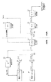
図1は、従来の単一チャネルLPAS音声符号器のブロック図である。この符号器は、2つの部分、すなわち、合成部と分析部とを具備している(これに対応する復号器は、合成部のみを有する)。
【0016】
合成部は、LPC合成フィルタ12を具備しており、そのLPC合成フィルタ12は、励振信号i(n)を受けて合成音声信号s^(n)を出力する(ここで、「s^(n)」は、上に^を付したsと(n)とを併記した図中の符号を指す)。励振信号i(n)は、2つの信号u(n)とv(n)を加算器22で加算することによって形成される。信号u(n)は、固定コードブック(fixed codebook)16からの信号f(n)をゲイン要素20におけるゲインgFでスケーリングすることによって形成される。信号v(n)は、適応コードブック(adaptive codebook)14からの励振信号i(n)の(遅延“lag”で)遅延されたものをゲイン要素18におけるゲインgAでスケーリングすることによって形成される。適応コードブックは、遅延要素24を含むフィードバック・ループによって形成され、その遅延要素24が励振信号i(n)を一サブフレームの長さNだけ遅延させるものとなっている。これにより、適応コードブックは、コードブック内にシフトされた過去の励振信号i(n)を有することになる(最も古い励振はコードブック外へシフトされて破棄される)。LPC合成フィルタのパラメータは、一般に20ms〜40msのフレーム毎にアップデートされるのに対し、適応コードブックは、5ms〜10msのサブフレーム毎にアップデートされる。
【0017】
LPAS符号器の分析部は、入来する音声信号s(n)のLPC分析を実行し、かつ、励振分析も実行する。
【0018】
LPC分析はLPC分析フィルタ10によって実行される。このフィルタは、音声信号s(n)を受け、その信号のパラメトリック・モデル(parametric model)をフレームベースで構築する。モデルのパラメータは、実際の音声フレームのベクトルとモデルによって生成される対応信号のベクトルとの差で形成される残差ベクトルのエネルギーを最小とするように選択される。モデルの各パラメータは、分析フィルタ10のフィルタ係数によって表される。それらのフィルタ係数は、フィルタの伝達関数A(z)を定める。合成フィルタ12の伝達関数は少なくとも近似的には1/A(z)に等しいため、それらのフィルタ係数はさらに、破線の制御線で示したように、合成フィルタ12を制御するものとなっている。
【0019】
励振分析は、音声信号ベクトル{s(n)}と最も適した合成信号ベクトル{s^(n)}を生じさせる、固定コードブックベクトル(コードブックのインデックス)、ゲインgF、適応コードブックベクトル(遅延)及びゲインgAの、最良の組合せを決定するために実行される(ここで、{}は、ベクトルないしフレームを形成するサンプルを収集したものを表す)。これは、それらのパラメータのすべての可能な組合せをテストする全数探索においてなされる(いくつかのパラメータを他のパラメータとは独立して定め、かつ、残ったパラメータの探索中それらを固定しておく準最適(sub−optimal)探索方式を採ることも可能である)。合成ベクトル{s^(n)}が対応する音声ベクトル{s(n)}にどのくらい近いかをテストするため、(加算器26で形成された)差ベクトル{e(n)}のエネルギーをエネルギー計算器30で計算することとしてもよい。しかし、重み付けされた誤差信号のベクトル{ew(n)}においては、大きい誤差を大きい振幅の周波数帯域(large amplitude frequency bands)によってマスクするような形態で誤差が再配分(re−distribute)されており、この重み付けされた誤差信号のベクトル{ew(n)}のエネルギーを考慮する方がより効率的である。これは、重み付けフィルタ28で行われる。
【0020】
次に、図1の単一チャネルLPAS符号器を参考文献3の記載に基づいて複数チャネルLPAS符号器とする変形について、図2〜図3を参照して説明する。音声信号として2つのチャネルの(ステレオの)音声信号を想定して説明を行うが、2つより多くのチャネルについて同様の原理を利用することとしてもよい。
【0021】
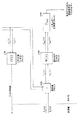
図2は、参考文献3に記載の複数チャネルLPAS音声符号器の分析部の一実施形態を示したブロック図である。図2においては、入力信号が信号成分s1(n)、s2(n)で示されているように複数チャネルの信号となっている。図1におけるLPC分析フィルタ10は、マトリクス値伝達関数行列A(z)を有するLPC分析フィルタ・ブロック10Mで置き換えられている。同様に、加算器26、重み付けフィルタ28、エネルギー計算器30は、それぞれ対応する複数チャネル用のブロック26M、28M、30Mによって置き換えられている。
【0022】
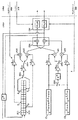
図3は、参考文献3に記載の複数チャネルLPAS音声符号器の合成部の一実施形態を示したブロック図である。複数チャネルの復号器もまた、このような合成部によって構成することとしてもよい。ここでは、図1におけるLPC合成フィルタ12が、マトリクス値伝達関数行列A−1(z)を有するLPC合成フィルタ・ブロック12Mで置き換えられている。この伝達関数行列A−1(z)は、(その表記文字記号が示すように)少なくとも近似的には行列A(z)の逆行列に等しいものとなっている。同様に、加算器22、固定コードブック16、ゲイン要素20、遅延要素24、適応コードブック14、ゲイン要素18は、それぞれ対応する複数チャネル用のブロック22M、16M、24M、14M、18Mによって置き換えられている。
【0023】
本発明に従って組み込まれた複数チャネルLPAS符号器のついての以下の記載により、様々なブロックにおいて符号化の柔軟性がどのように改善されたかが明らかにされている。しかし、全てのブロックを記載された方法で構成しなくてはならないわけではない。符号化の柔軟性と複雑性とのバランスは個別の符号器の態様に応じて定められなくてはならない。
【0024】
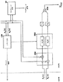
図4は、本発明の複数チャネルLPAS音声符号器の合成部の実施態様の一例を示したブロック図である。
【0025】
符号器の本質的特徴は、マルチパート固定コードブックの構造である。それには各チャネルについての個別の固定コードブックFC1、FC2が含まれている。典型的には、固定コードブックは、代数的なコードブックを具備し、該コードブックにおいて、ある規則に従ってそれぞれのベクトルに配分されたユニットパルスにより励振ベクトルが形成される(これは当業者にとって周知であるから、本書ではさらに詳述しない)。各固定コードブックFC1、FC2は、個別のゲインgF1、gF2に関連している。本発明の本質的な特徴は、固定コードブックの一つ、典型的には最も強いまたは先頭の(単一の)チャネルに関連しているコードブックが、一遅延要素D(整数または分数であってもよい)にわたるより弱いまたは後続のチャネルと、チャネル間のゲインgF12とによって共有される点である。
【0026】
各チャネルが同一信号をスケーリングし変換したチャネルからなる理想的な場合(エコーがない空間)、先頭チャネルの共有コードブックが必要とされるのみであり、遅延値Dは、音伝搬時間に直接対応している。チャネル間の相互相関が非常に低い、上記と反対の場合では、後続チャネルのための個別の固定コードブックが必要とされる。
【0027】
固定コードブックにクロスチャネルブランチが1つだけの場合、先頭チャネルと後続チャネルはフレームごとに定められなければならない。先頭チャネルは変わりうるので、遅延DとゲインgF12を適切なチャネルに関連させるための同調的に制御されたスイッチSW1とSW2がある。図4の構成では、チャネル1が先頭チャネルであり、チャネル2が後続チャネルである。両スイッチSW1とSW2をそれらの正反対の状態に切り替えることによって、役割が逆転される。先頭チャネルの重たい切り替えを回避するために、多数の連続フレームのために同一の先頭チャネルが選択されている場合のみ変更を可能とすることが必要となる。
【0028】
あるいは、後続チャネル固定コードブックのためのパルスの使用を先頭チャネル固定コードブックのパルスより少なくしてもよい。この実施態様では、固定コードブックの長さは、チャネルが後続チャネルに降格すると小さくなり、先頭チャネルに戻ると当初の大きさに戻される。
【0029】
図4は、2チャネル固定コードブック構造を図示しているが、各コードブックの数と遅延及びチャネル間のゲインの数を増加させることによって、この概念はより多くのチャネルに対して容易に一般化できることが理解されなければならない。
【0030】
先頭チャネルと後続チャネルの固定コードブックは、典型的には連続して順番に調べられる。好適な順序としては、第一に先頭チャネル固定コードブック励振ベクトル、遅延及びゲインを決定し、その後、後続チャネルの個別の固定コードブックベクトルとゲインを決定する。
【0031】
図5は、本発明のマルチパート固定コードブックの実施態様のフローチャートである。ステップS1は(最大のフレームエネルギーを有するチャネル)先頭チャネル、典型的には最も強いチャネルを判断し符号化する。ステップS2は、所定の間隔(例えば完全な一フレームの一部分)の各後続チャネルと先頭チャネルの間の相互相関を判断する。ステップS3は、各後続チャネルについての遅延候補を記憶する。これらの遅延候補は、多数の最高の相互相関のピークの位置と、各後続チャネルについての各ピークのまわりの最も近傍の位置によって定義される。例えば3つの最高ピークを選択し、各ピークの両側の最も近い位置を付加することによって、後続チャネルについて総計9つの遅延候補を与えることになる。高分解(分数)遅延を使用した場合は、各ピークのまわりの候補数を、例えば5ないし7に増加できる。より高い分解は入力信号のアップサンプリングによって得ることができる。ステップS4は、最高の遅延組み合わせを選択する。ステップS5は、最適のチャネル間ゲインを判断する。最後にステップS6は、後続チャネルの励振とゲインを判断する。
【0032】
固定コードブックゲインについては、各後続チャネルは、先頭チャネル固定コードブックに対して1チャネル間ゲインを必要とし、個別コードブックについては1ゲインを必要とする。これらのゲインは、典型的にはチャネル間で著しい相関関係を有している。これらはまた適応コードブックのゲインと相関付けられる。従ってこれらのゲインのチャネル間予測が可能である。
【0033】
図4に戻り、マルチパート適応コードブックは、各チャネルにつき1つの適応コードブックAC1、AC2を含む。マルチパート適応コードブックは複数チャネル符号器において多数の方法で構成されうる。例えば:
1.全てのチャネルはシングルピッチの遅延を共有する。各チャネルは、予測を改善するために個別にピッチゲインgA11、gA22を有してもよい。共有ピッチの遅延は、閉じられたループの態様で先頭(単一)チャネルで探索され、その後後続チャネルで使用される。
2.チャネルは、個別のピッチの遅延P11、P22を有する。後続チャネルのピッチ遅延値は、先頭チャネルのピッチ遅延と異なるように、または独立して、符号化されうる。後続チャネルのピッチ遅延の探索は、先頭(単一)チャネルのピッチ遅延値の周りでなされる。
3.励振履歴をチャネル横断の態様で使用することができる。遅延距離P12で先頭チャネル1からの励振履歴を有する予測チャネル2等の1個のチャネル横断励振ブランチを使用することができる。同調的に制御されたスイッチSW3とSW4は、どのチャネルが先頭なのかに応じて、チャネル横断励振を適切な加算器AA1、AA2に、チャネル横断ゲインgA12を通じて接続する。
【0034】
固定コードブックに関する場合のように、記載された適応コードブックの構造は非常に柔軟で、マルチモード操作に適している。共有ピッチ遅延または個別のピッチ遅延を使用するか否かの選択は残差信号エネルギーに基づいてもよい。第一のステップでは、最適な共有ピッチ遅延の残差エネルギーが決定される。第二のステップでは、最適な個別のピッチ遅延の残差エネルギーが決定される。共有ピッチ遅延の場合の残差エネルギーが個別のピッチ遅延の場合の残差エネルギーよりも所定量超過している場合、個別のピッチ遅延が使用される。そうでない場合は、共有ピッチ遅延が使用される。希望であれば、決定を円滑にするためにエネルギー差の平均移動を用いてもよい。
【0035】
この方策は、共有ピッチ遅延か個別のピッチ遅延かを決定するための「閉ループ」方法と考えることができる。あるいは、チャネル間相関等に基づく「開ループ」方法も可能である。この場合、チャネル間相関が所定の閾値を越える場合、共有ピッチ遅延が使用される。そうでない場合は、個別のピッチ遅延が使用される。
【0036】
チャネル間のピッチ遅延を使用するか否かを決定するために同様の方法を使用することができる。
【0037】
さらに、異なるチャネル間の適応コードブックゲインの間で重要な相関が期待されている。これらのゲインは、チャネルの内部ゲイン履歴から、他のチャネルに属する同一フレームのゲインから、及び固定コードブックゲインからも予測されうる。
【0038】
図4のLPC合成フィルタ・ブロック12Mでは、各チャネルは個別のLPC(線形予測符号化)フィルタを使用する。これらのフィルタは、単一チャネルの場合と同様の方法で個別に駆動することができる。しかし、チャネルの一部または全部が同一LPCフィルタを共有することもできる。これによって、LPCスペクトル間のスペクトル距離等の信号特性に応じて、複数フィルタモードと単一フィルタモードとを切り替えることができる。チャネル間予測をLSP(線スペクトル対)パラメータのために使用すると、該予測は低相関モードのために停止されるかまたは低減される。
【0039】
図6は、本発明の複数チャネルLPAS音声符号器の分析部の実施態様の一例を示すブロック図である。図1と図2を参照しながらすでに説明したブロックに加えて、図6に記載の分析部は、複数モード分析ブロック40を含む。ブロック40は、先頭チャネルの固定コードブック、遅延D及びゲインgF12のみを使用した後続チャネルの符号化を正当化するのに後続チャネルと先頭チャネルの間に十分な相関があるか否かを判断するために、チャネル間の相関を判断する。もしそうでない場合は、後続チャネルのために個別の固定コードブックとゲインを使用することが必要となるであろう。該相関は、時間ドメインにおける通常の相関、つまり、第二のチャネル信号を第一の信号に最も良く適合するまでシフトすることによって判断することができる。2つ以上のチャネルが存在する場合には、最小相関値が所定の閾値を超過したときに先頭チャネル固定コードブックが共有固定コードブックとして使用されることになる。あるいは、先頭チャネルに対する相関が所定の閾値を超過するチャネルのために共有固定コードブックを使用し、残りのチャネルのために個別の固定コードブックを使用してもよい。正確な閾値はリスニングテストによって判断される。
【0040】
本発明の上記に記載の実施態様の様々な要素の機能は、典型的には一または複数のマイクロプロセッサまたはマイクロ/信号プロセッサの組合せ、及びこれに対応するソフトウェアによって実行される。
【0041】
図面において、幾つかのブロック及びパラメータは任意のものであり、複数チャネル信号の特性及び音声品質の全体的な要求基準に応じて使用することができる。符号器のビットは、それらが最も必要とされている所に割り当てることができる。符号器は、フレームごとに選択してLPC部分、適応及び固定コードブックの間に様々にビットを分配する。これは、チャネル内マルチモード操作の一例である。
【0042】
マルチモード操作のさらなる例は、符号器のビットをチャネル間に分配するということ(非対称符号化)である。これは、チャネル間マルチモード操作と称される。ここでの一例は、一/複数のチャネルまたは一チャネルにおける複数のビットで符号化された符号器ゲインのためのより大きな固定コードブックであろう。ソース信号特性を効率的に活用するために該2つのマルチモード操作例を組み合わせることができる。
【0043】
該マルチモード操作は、閉ループ態様でまたは開ループ方法で制御することができる。閉ループ方法は、各モードについての残差符号化エラーに応じてモードを判断する。これは計算上、金のかかる方法である。開ループ方法では、符号化モードは、入力信号特性に基づく決定によって判断される。チャネル内の場合は、参考文献4に記載されたように、音声、スペクトル特性及び信号エネルギー等に基づいて、可変レートモードが判断される。チャネル間モードの決定のためには、チャネル間相互相関関数またはスペクトル距離関数が使用されモードが決定される。ノイズまたは無声符号化のためには、周波数ドメインにおける複数チャネル相関特性を使用することがより適切である。開ループと閉ループ技術の組み合わせも可能である。開ループ分析は、複数の候補モードを決定し、これらは符号化され、そして閉ループ決定時に最終残差エラーが使用される。
【0044】
(先頭チャネルと後続チャネルの間の)複数チャネル予測は、複数チャネルLPASゲイン及びLPCパラメータのために必要なビット数を減らすための高チャネル間相関モードのために使用することができる。
【0045】
一般化されたLPAS(参考文献5参照)としてすでに知られている技術を本発明の複数チャネルLPAS符号器に使用することもできる。簡単にいうと、この技術は実際の符号化前のフレームごとの入力信号の前処理に関係している。複数の可能性ある修正信号を検査し、最小の歪みで符号化されうる信号が符号化されるべき信号として選択される。
【0046】
上記の説明は主として符号器を対象としている。これに対応する復号器は、このような符号器の合成部を含むのみでありうる。典型的には、符号器/復号器の組み合わせは、帯域幅制限通信チャネル上で符号化信号を伝送/受信する端末において使用される。端末は、携帯電話または基地局の無線端末であってもよい。そのような端末は、アンテナ、増幅器、イコライザ、チャネル符号器/復号器等の他の様々な要素も含みうる。しかし、これらの要素は、本発明を説明するために重要ではないので、その説明は省略されている。
【0047】
本発明の範囲から逸脱することなく、本発明に対して様々な変形や変更がなされ得るのは、当業者に理解されるところであり、本発明の範囲は特許請求の範囲の記載によって定められる。
【0048】
参考文献
[1] A. Gersho, “Advances in Speech and Audio Compression”, Proc. of the IEEE, Vol. 82, No. 6, pp 900−918, June 1994,
[2] A. S. Spanias, “Speech Coding: A Tutorial Review”, Proc. of the IEEE, Vol 82, No. 10, pp 1541−1582, Oct 1994.
[3] WO00/19413(Telefonaktiebolaget LM Ericsson).
[4] Allen Gersho et.al, ”Variable rate speech coding for cellular networks”, page 77−84, Speech and audio coding for wireless and network applications, Kluwer Academic Press, 1993.
[5] Bastiaan Kleijn et.al, ”Generalized analysis−by−synthesis coding and its application to pitch prediction”, page 337−340, In Proc. IEEE Int. Conf. Acoust., Speech and Signal Processing, 1992.
【図面の簡単な説明】
【図1】従来の単一チャネルLPAS音声符号器のブロック図である。
【図2】従来の複数チャネルLPAS音声符号器の分析部の一実施態様を示したブロック図である。
【図3】従来の複数チャネルLPAS音声符号器の合成部の一実施態様を示したブロック図である。
【図4】本発明の複数チャネルLPAS音声符号器の分析部の実施態様の一例を示したブロック図である。
【図5】マルチパート固定コードブックの探索方法の実施態様の一例のフローチャートである。
【図6】本発明の複数チャネルLPAS音声符号器の分析部の実施態様の一例を示したブロック図である。[0001]
TECHNICAL FIELD OF THE INVENTION
The present invention relates to encoding and decoding of a multi-channel signal such as a stereo sound signal.
[0002]
Problems to be solved by the prior art and the invention
Conventional speech coding methods are generally based on a single-channel speech signal. Voice coding used in the connection between a permanent telephone and a mobile telephone is one example. Speech coding is used over wireless links to reduce bandwidth usage over frequency-limited airwave interfaces. Examples of well-known speech coding include Pulse Code Modulation (PCM), Adaptive Differential Pulse Code Modulation (ADPCM), sub-band coding (trans-band coding), and sub-band coding (transform coding (transcoding) coding). There are voice-activated coding of Linear Predictive Coding and hybrid coding such as CELP (Code-Excited Linear Predictive) coding [references 1-2].
[0003]
In an environment where more than one input signal is used for audio / speech communication, such as a computer workstation having stereo speakers and two microphones (stereo microphones), two or more input signals are required to transmit the stereo signal. Two audio / voice channels are required. Another example of an environment using multiple channels would be a conference room with two, three or four channels of input / output. Such applications are expected to be used on the Internet and in third-generation mobile telephone systems.
[0004]
In a communication system, the total bit rate available for a speech encoder depends on the capabilities of the different links. In certain situations, such as the high interface of a wireless link or the network overload of a fixed link, the available bit rate may decrease. In a stereo communication situation, this means a packet loss / wrong frame or, for a multi-mode coder, a reduction in the bit rate of both channels, in each case a reduction in the quality of both channels.
[0005]
A further problem is the placement of stereo capable terminals. All acoustic communication terminals use a single channel, such as adaptive multi-rate (AMR) speech encoding / decoding, and the fallback mode of a stereo terminal is single channel. If the stakeholder is one single terminal in multiple stereo conferences (eg, a multicast session), the use and high quality of stereo coding will be limited due to the need for interoperability.
[0006]
General principles for multi-channel linear predictive synthesis analysis (LPAS) signal encoding / decoding are described in ref. However, the described encoder is not flexible enough to address the above problems.
[Means for Solving the Problems]
[0007]
It is an object of the present invention to find an efficient multi-channel LPAS speech coding structure that exploits inter-channel signal correlation and maintains an embedded bit stream.
[0008]
A further object is to create, on average, a single-channel audio coder bitstream M times less bitstream per M-channel audio signal while maintaining the same or better audio quality at any average bit rate. is there.
[0009]
Another challenge is the rational implementation and computational complexity of implementing the encoder in the structure.
[0010]
The above object is solved by the appended claims.
[0011]
Briefly, the present invention relates to incorporating a single channel into a multi-channel coded bitstream and overcoming quality issues associated with different total bit rates, such as due to different link qualities. With these arrangements, if there is a need to reduce the total bit rate, the embedded single channel bit stream is maintained and the other channel is ignored. The communication will then "back off" to a single encoding operation with a lower total bit rate, but still maintain a high single quality. It is possible to drop the "stereo" bits at any point of communication and add more channel coded bits for greater reliability in wireless communication scenarios. "Stereo" bits can also be dropped depending on the capabilities of the receiver. If there is a single decoder at the receiver of one party in a multi-party conference, the dropped single bit stream can be used to incorporate the single bit stream.
[0012]
BRIEF DESCRIPTION OF THE DRAWINGS The invention can be best understood with reference to the description that is set forth in conjunction with the accompanying drawings. At the same time, further objects and advantages of the present invention may be best understood by referring to the description taken in conjunction with the accompanying drawings.
[0013]
In the following description, equivalent or similar elements are denoted by the same reference numerals.
[0014]
BEST MODE FOR CARRYING OUT THE INVENTION
The present invention will be described through the description of a conventional single-channel linear predictive synthesis analysis (LPAS) speech coder and a general multi-channel linear predictive synthesis analysis speech coder (Ref. 3).
[0015]
FIG. 1 is a block diagram of a conventional single channel LPAS speech coder. This encoder has two parts, a synthesis unit and an analysis unit (the corresponding decoder has only a synthesis unit).
[0016]
The synthesis unit includes an
[0017]
The analyzer of the LPAS encoder performs an LPC analysis of the incoming speech signal s (n) and also performs an excitation analysis.
[0018]
The LPC analysis is performed by the
[0019]
The excitation analysis yields a fixed codebook vector (codebook index), a gain gF, an adaptive codebook vector (codebook vector) that yields the speech signal vector {s (n)} and the best combined signal vector {s {(n)}. Delay) and gain gA are performed to determine the best combination (where {} represents a collection of samples forming a vector or frame). This is done in an exhaustive search that tests all possible combinations of those parameters (defining some parameters independently of other parameters and keeping them fixed during the search for remaining parameters It is also possible to adopt a sub-optimal search method). To test how close the synthesized vector {s} (n)} is to the corresponding speech vector {s (n)}, the energy of the difference vector {e (n)} (formed by adder 26) is The calculation may be performed by the
[0020]
Next, a modification in which the single-channel LPAS encoder of FIG. 1 is replaced with a multi-channel LPAS encoder based on the description in Reference 3 will be described with reference to FIGS. The description will be made on the assumption that the audio signal is a two-channel (stereo) audio signal, but the same principle may be used for more than two channels.
[0021]
FIG. 2 is a block diagram showing an embodiment of the analysis unit of the multi-channel LPAS speech encoder described in Reference 3. In FIG. 2, the input signal is a signal of a plurality of channels as shown by signal components s1 (n) and s2 (n). The
[0022]
FIG. 3 is a block diagram showing an embodiment of the synthesis unit of the multi-channel LPAS speech encoder described in Reference 3. A multi-channel decoder may also be configured with such a combining unit. Here, the
[0023]
The following description of a multi-channel LPAS encoder incorporated in accordance with the present invention demonstrates how the coding flexibility in various blocks has been improved. However, not all blocks have to be constructed in the manner described. The balance between coding flexibility and complexity must be determined according to the particular encoder implementation.
[0024]
FIG. 4 is a block diagram showing an example of an embodiment of the synthesis unit of the multi-channel LPAS speech encoder according to the present invention.
[0025]
An essential feature of the encoder is the structure of the multipart fixed codebook. It contains individual fixed codebooks FC1, FC2 for each channel. Typically, a fixed codebook comprises an algebraic codebook, in which the excitation vector is formed by unit pulses allocated to each vector according to certain rules (this is well known to those skilled in the art). Therefore, it is not described in detail in this document). Each fixed codebook FC1, FC2 is associated with a separate gain gF1, gF2. An essential feature of the present invention is that one of the fixed codebooks, typically the codebook associated with the strongest or leading (single) channel, is one delay element D (integer or fractional). May be shared by weaker or subsequent channels over the same channel and gain gF12 between channels.
[0026]
In the ideal case where each channel is composed of channels obtained by scaling and converting the same signal (space without echo), only the shared codebook of the first channel is required, and the delay value D directly corresponds to the sound propagation time. are doing. In the opposite case, where the cross-correlation between the channels is very low, a separate fixed codebook for subsequent channels is required.
[0027]
If the fixed codebook has only one cross-channel branch, the leading channel and the succeeding channel must be determined for each frame. Since the leading channel can vary, there are tuned switches SW1 and SW2 to associate the delay D and gain gF12 with the appropriate channel. In the configuration of FIG. 4,
[0028]
Alternatively, the pulses for the subsequent channel fixed codebook may be used less than the pulses for the first channel fixed codebook. In this embodiment, the length of the fixed codebook decreases when the channel is demoted to a subsequent channel and returns to its original size when returning to the first channel.
[0029]
FIG. 4 illustrates a two-channel fixed codebook structure, but by increasing the number of each codebook and the number of delays and gains between channels, this concept can be easily generalized for more channels. It must be understood that
[0030]
The fixed codebooks of the first and subsequent channels are typically consulted sequentially and sequentially. A preferred order is to first determine the leading channel fixed codebook excitation vector, delay and gain, and then determine the individual fixed codebook vectors and gain for the subsequent channels.
[0031]
FIG. 5 is a flowchart of an embodiment of the multipart fixed codebook of the present invention. Step S1 determines and encodes the first channel (the channel with the highest frame energy), typically the strongest channel. Step S2 determines the cross-correlation between each subsequent channel and the first channel at a predetermined interval (for example, a part of a complete frame). Step S3 stores the delay candidates for each subsequent channel. These delay candidates are defined by the location of the peaks of the highest number of cross-correlations and the nearest location around each peak for each subsequent channel. For example, selecting the three highest peaks and adding the closest positions on both sides of each peak will give a total of nine delay candidates for subsequent channels. If a high resolution (fractional) delay is used, the number of candidates around each peak can be increased, for example, to 5-7. Higher resolution can be obtained by upsampling the input signal. Step S4 selects the best delay combination. A step S5 judges an optimum inter-channel gain. Finally, step S6 determines the excitation and gain of the subsequent channel.
[0032]
For the fixed codebook gain, each subsequent channel requires one inter-channel gain for the leading channel fixed codebook, and one gain for the individual codebook. These gains typically have a significant correlation between the channels. These are also correlated with the adaptive codebook gain. Therefore, inter-channel prediction of these gains is possible.
[0033]
Referring back to FIG. 4, the multi-part adaptive codebook includes one adaptive codebook AC1, AC2 for each channel. A multipart adaptive codebook may be configured in a multi-channel encoder in a number of ways. For example:
1. All channels share a single pitch delay. Each channel may have its own pitch gain g A11 , g A22 to improve the prediction. The shared pitch delay is searched for in the leading (single) channel in a closed loop manner and then used in subsequent channels.
2. The channels have discrete pitch delays P 11 , P 22 . The pitch delay value of the subsequent channel may be encoded differently or independently of the pitch delay of the first channel. The search for the pitch delay of the subsequent channel is made around the pitch delay value of the leading (single) channel.
3. The excitation history can be used in a cross channel manner. It can be used one channel transverse excitation branches
[0034]
As with the fixed codebook, the structure of the described adaptive codebook is very flexible and suitable for multi-mode operation. The choice of whether to use a shared pitch delay or a separate pitch delay may be based on the residual signal energy. In the first step, the residual energy of the optimal shared pitch delay is determined. In the second step, the optimal individual pitch delay residual energy is determined. If the residual energy for the shared pitch delay exceeds the residual energy for the individual pitch delay by a predetermined amount, the individual pitch delay is used. Otherwise, a shared pitch delay is used. If desired, the average shift of the energy difference may be used to facilitate the decision.
[0035]
This strategy can be thought of as a "closed loop" method for determining whether a shared pitch delay or individual pitch delay. Alternatively, an “open loop” method based on inter-channel correlation or the like is also possible. In this case, if the inter-channel correlation exceeds a predetermined threshold, a shared pitch delay is used. Otherwise, a separate pitch delay is used.
[0036]
A similar method can be used to determine whether to use pitch delay between channels.
[0037]
In addition, significant correlations are expected between the adaptive codebook gains between different channels. These gains can be predicted from the internal gain history of the channel, from the gain of the same frame belonging to another channel, and also from the fixed codebook gain.
[0038]
In the LPC
[0039]
FIG. 6 is a block diagram showing an example of an embodiment of the analysis unit of the multi-channel LPAS speech encoder according to the present invention. In addition to the blocks already described with reference to FIGS. 1 and 2, the analysis unit shown in FIG. 6 includes a
[0040]
The functions of the various elements of the above-described embodiments of the invention are typically performed by one or more microprocessors or combinations of micro / signal processors and corresponding software.
[0041]
In the figures, some blocks and parameters are optional and can be used depending on the characteristics of the multi-channel signal and the overall requirements of voice quality. Encoder bits can be assigned where they are needed most. The encoder selects and distributes various bits between the LPC part, the adaptive and fixed codebooks on a frame-by-frame basis. This is an example of intra-channel multi-mode operation.
[0042]
A further example of multimode operation is to distribute the bits of the encoder between channels (asymmetric coding). This is called inter-channel multi-mode operation. An example here would be a larger fixed codebook for encoder gain coded with one / multiple channels or multiple bits in one channel. The two multi-mode operation examples can be combined to make efficient use of the source signal characteristics.
[0043]
The multi-mode operation can be controlled in a closed loop manner or in an open loop manner. The closed loop method determines the mode according to the residual coding error for each mode. This is computationally expensive. In the open loop method, the coding mode is determined by a decision based on the input signal characteristics. In the case of the inside of the channel, as described in
[0044]
Multi-channel prediction (between the first and subsequent channels) can be used for a high inter-channel correlation mode to reduce the number of bits required for multi-channel LPAS gain and LPC parameters.
[0045]
The technique already known as generalized LPAS (see reference 5) can also be used for the multi-channel LPAS encoder of the present invention. Briefly, this technique involves preprocessing the input signal on a frame-by-frame basis before the actual encoding. A plurality of possible modified signals are examined and the signal that can be coded with minimal distortion is selected as the signal to be coded.
[0046]
The above description is primarily directed to encoders. The corresponding decoder may only include the synthesis part of such an encoder. Typically, an encoder / decoder combination is used in a terminal that transmits / receives an encoded signal over a bandwidth limited communication channel. The terminal may be a mobile phone or a base station wireless terminal. Such a terminal may also include various other components such as an antenna, an amplifier, an equalizer, a channel encoder / decoder. However, these elements are not important for describing the present invention, and thus the description thereof has been omitted.
[0047]
It is understood by those skilled in the art that various modifications and changes can be made to the present invention without departing from the scope of the present invention, and the scope of the present invention is defined by the appended claims.
[0048]
Reference [1] Gersho, "Advances in Speech and Audio Compression", Proc. of the IEEE, Vol. 82, no. 6, pp 900-918, June 1994,
[2] A. S. Spanias, "Speech Coding: A Tutorial Review", Proc. of the IEEE, Vol 82, no. 10, pp 1541-1582, Oct 1994.
[3] WO 00/19413 (Telefonaktiebolaget LM Ericsson).
[4] Allen Gersho et. al, "Variable rate speech coding for cellular networks", page 77-84, Speech and audio coding for wireless and publishing in 1993.
[5] Bastian Kleijn et. al, "Generalized analysis-by-synthesis coding and it's applications to pitch prediction", page 337-340, In Proc. IEEE Int. Conf. Acoustic. , Speech and Signal Processing, 1992.
[Brief description of the drawings]
FIG. 1 is a block diagram of a conventional single channel LPAS speech coder.
FIG. 2 is a block diagram showing an embodiment of an analysis unit of a conventional multi-channel LPAS speech coder.
FIG. 3 is a block diagram showing one embodiment of a synthesis unit of a conventional multi-channel LPAS speech coder.
FIG. 4 is a block diagram showing an example of an embodiment of an analysis unit of the multi-channel LPAS speech encoder of the present invention.
FIG. 5 is a flowchart of an example of an embodiment of a multipart fixed codebook search method.
FIG. 6 is a block diagram showing an example of an embodiment of an analysis unit of the multi-channel LPAS speech encoder of the present invention.
Claims (26)
組み込まれたビットストリームとして該先頭チャネルを符号化するステップと;
後続チャネルを無視できるビットストリームとして符号化するステップ
を含む複数チャネル線形予測分析合成信号符号化方法。Determining a first channel and at least one subsequent channel;
Encoding the head channel as an embedded bit stream;
A multi-channel linear prediction analysis and synthesis signal encoding method comprising encoding subsequent channels as negligible bit streams.
高チャネル間相関のために該先頭チャネルLPCフィルタを共有するステップを含む、請求項2ないし4のいずれか1項に記載の方法。Using a channel specific LPC filter for low inter-channel correlation;
5. The method according to any one of claims 2 to 4, comprising sharing the leading channel LPC filter for high inter-channel correlation.
高チャネル間相関のために該先頭チャネル固定コードブックを共有するステップを含む、請求項2ないし4のいずれか1項に記載の方法。Using a channel specific fixed codebook for low inter-channel correlation;
5. The method according to any one of claims 2 to 4, comprising sharing the leading channel fixed codebook for high inter-channel correlation.
高チャネル間相関のために共有適応コードブック遅延を使用するステップを含む、請求項2ないし4のいずれか1項に記載の方法。Using a channel-specific adaptive codebook delay for low inter-channel correlation;
5. The method according to any one of claims 2 to 4, comprising using a shared adaptive codebook delay for high inter-channel correlation.
組み込まれたビットストリームとして該先頭チャネルを符号化する手段と;
後続チャネルを無視できるビットストリームとして符号化する手段
を含む複数チャネル線形予測分析合成信号符号器。Means for determining a leading channel and at least one trailing channel;
Means for encoding said leading channel as an embedded bit stream;
A multi-channel linear prediction analysis and synthesis signal encoder including means for encoding subsequent channels as negligible bit streams.
高チャネル間相関のための共有先頭チャネルLPCフィルタを含む、請求項12に記載の符号器。A channel specific LPC filter for low inter-channel correlation;
The encoder of claim 12, comprising a shared leading channel LPC filter for high inter-channel correlation.
高チャネル間相関のための共有先頭チャネル固定コードブックを含む、請求項12に記載の符号器。A channel specific fixed codebook for low inter-channel correlation;
The encoder of claim 12, comprising a shared head channel fixed codebook for high inter-channel correlation.
高チャネル間相関のための共有適応コードブック遅延を含む、請求項12に記載の符号器。Channel specific adaptive codebook delay for low inter-channel correlation;
The encoder of claim 12, comprising a shared adaptive codebook delay for high inter-channel correlation.
組み込まれたビットストリームとして該先頭チャネルを符号化する手段と;
後続チャネルを無視できるビットストリームとして符号化する手段
を含む複数チャネル線形予測分析合成信号符号器を具備した端末。Means for determining a leading channel and at least one trailing channel;
Means for encoding said leading channel as an embedded bit stream;
A terminal comprising a multi-channel linear prediction analysis and synthesis signal encoder including means for encoding a subsequent channel as a negligible bit stream.
高チャネル間相関のための共有先頭チャネルLPCフィルタを含む、請求項20に記載の端末。A channel specific LPC filter for low inter-channel correlation;
The terminal according to claim 20, comprising a shared leading channel LPC filter for high inter-channel correlation.
高チャネル間相関のための共有先頭チャネル固定コードブックを含む、請求項20に記載の端末。A channel specific fixed codebook for low inter-channel correlation;
The terminal according to claim 20, comprising a shared leading channel fixed codebook for high inter-channel correlation.
高チャネル間相関のための共有適応コードブック遅延を含む、請求項20に記載の端末。Channel specific adaptive codebook delay for low inter-channel correlation;
The terminal of claim 20, comprising a shared adaptive codebook delay for high inter-channel correlation.
Applications Claiming Priority (2)
| Application Number | Priority Date | Filing Date | Title |
|---|---|---|---|
| SE0003287A SE519985C2 (en) | 2000-09-15 | 2000-09-15 | Coding and decoding of signals from multiple channels |
| PCT/SE2001/001886 WO2002023529A1 (en) | 2000-09-15 | 2001-09-05 | Multi-channel signal encoding and decoding |
Publications (2)
| Publication Number | Publication Date |
|---|---|
| JP2004509367A true JP2004509367A (en) | 2004-03-25 |
| JP4498677B2 JP4498677B2 (en) | 2010-07-07 |
Family
ID=20281034
Family Applications (1)
| Application Number | Title | Priority Date | Filing Date |
|---|---|---|---|
| JP2002527493A Expired - Fee Related JP4498677B2 (en) | 2000-09-15 | 2001-09-05 | Multi-channel signal encoding and decoding |
Country Status (8)
| Country | Link |
|---|---|
| US (1) | US7263480B2 (en) |
| EP (1) | EP1325495B1 (en) |
| JP (1) | JP4498677B2 (en) |
| AT (1) | ATE358317T1 (en) |
| AU (1) | AU2001286350A1 (en) |
| DE (1) | DE60127566T2 (en) |
| SE (1) | SE519985C2 (en) |
| WO (1) | WO2002023529A1 (en) |
Cited By (4)
| Publication number | Priority date | Publication date | Assignee | Title |
|---|---|---|---|---|
| WO2006035705A1 (en) * | 2004-09-28 | 2006-04-06 | Matsushita Electric Industrial Co., Ltd. | Scalable encoding apparatus and scalable encoding method |
| JP4812230B2 (en) * | 2000-09-15 | 2011-11-09 | テレフオンアクチーボラゲット エル エム エリクソン(パブル) | Multi-channel signal encoding and decoding |
| JP4809370B2 (en) * | 2005-02-23 | 2011-11-09 | テレフオンアクチーボラゲット エル エム エリクソン(パブル) | Adaptive bit allocation in multichannel speech coding. |
| US9626973B2 (en) | 2005-02-23 | 2017-04-18 | Telefonaktiebolaget L M Ericsson (Publ) | Adaptive bit allocation for multi-channel audio encoding |
Families Citing this family (23)
| Publication number | Priority date | Publication date | Assignee | Title |
|---|---|---|---|---|
| JP3273599B2 (en) * | 1998-06-19 | 2002-04-08 | 沖電気工業株式会社 | Speech coding rate selector and speech coding device |
| FI121583B (en) * | 2002-07-05 | 2011-01-14 | Syslore Oy | Finding a Symbol String |
| CN1973319B (en) * | 2004-06-21 | 2010-12-01 | 皇家飞利浦电子股份有限公司 | Method and apparatus to encode and decode multi-channel audio signals |
| CN1989546B (en) * | 2004-07-20 | 2011-07-13 | 松下电器产业株式会社 | Sound encoder and sound encoding method |
| CN101010725A (en) * | 2004-08-26 | 2007-08-01 | 松下电器产业株式会社 | Multichannel signal coding equipment and multichannel signal decoding equipment |
| CN101031960A (en) | 2004-09-30 | 2007-09-05 | 松下电器产业株式会社 | Scalable encoding device, scalable decoding device, and method thereof |
| US7848932B2 (en) | 2004-11-30 | 2010-12-07 | Panasonic Corporation | Stereo encoding apparatus, stereo decoding apparatus, and their methods |
| EP1818911B1 (en) * | 2004-12-27 | 2012-02-08 | Panasonic Corporation | Sound coding device and sound coding method |
| BRPI0519454A2 (en) * | 2004-12-28 | 2009-01-27 | Matsushita Electric Ind Co Ltd | rescalable coding apparatus and rescalable coding method |
| EP1847988B1 (en) | 2005-02-10 | 2011-08-17 | Panasonic Corporation | Voice coding |
| EP1691348A1 (en) * | 2005-02-14 | 2006-08-16 | Ecole Polytechnique Federale De Lausanne | Parametric joint-coding of audio sources |
| US8000967B2 (en) * | 2005-03-09 | 2011-08-16 | Telefonaktiebolaget Lm Ericsson (Publ) | Low-complexity code excited linear prediction encoding |
| KR101346120B1 (en) * | 2005-03-30 | 2014-01-02 | 코닌클리케 필립스 엔.브이. | Audio encoding and decoding |
| JP4599558B2 (en) * | 2005-04-22 | 2010-12-15 | 国立大学法人九州工業大学 | Pitch period equalizing apparatus, pitch period equalizing method, speech encoding apparatus, speech decoding apparatus, and speech encoding method |
| RU2007139784A (en) * | 2005-04-28 | 2009-05-10 | Мацусита Электрик Индастриал Ко., Лтд. (Jp) | AUDIO ENCODING DEVICE AND AUDIO ENCODING METHOD |
| EP1876585B1 (en) * | 2005-04-28 | 2010-06-16 | Panasonic Corporation | Audio encoding device and audio encoding method |
| FR2916079A1 (en) * | 2007-05-10 | 2008-11-14 | France Telecom | AUDIO ENCODING AND DECODING METHOD, AUDIO ENCODER, AUDIO DECODER AND ASSOCIATED COMPUTER PROGRAMS |
| WO2009038512A1 (en) * | 2007-09-19 | 2009-03-26 | Telefonaktiebolaget Lm Ericsson (Publ) | Joint enhancement of multi-channel audio |
| US8515767B2 (en) * | 2007-11-04 | 2013-08-20 | Qualcomm Incorporated | Technique for encoding/decoding of codebook indices for quantized MDCT spectrum in scalable speech and audio codecs |
| NO2669468T3 (en) * | 2011-05-11 | 2018-06-02 | ||
| CN110728986B (en) | 2018-06-29 | 2022-10-18 | 华为技术有限公司 | Coding method, decoding method, coding device and decoding device for stereo signal |
| GB2580899A (en) * | 2019-01-22 | 2020-08-05 | Nokia Technologies Oy | Audio representation and associated rendering |
| CN112233682A (en) * | 2019-06-29 | 2021-01-15 | 华为技术有限公司 | Stereo coding method, stereo decoding method and device |
Citations (7)
| Publication number | Priority date | Publication date | Assignee | Title |
|---|---|---|---|---|
| JPH10105193A (en) * | 1996-09-26 | 1998-04-24 | Yamaha Corp | Speech encoding transmission system |
| JPH1132399A (en) * | 1997-05-13 | 1999-02-02 | Sony Corp | Coding method and system and recording medium |
| JPH1188184A (en) * | 1997-02-05 | 1999-03-30 | Nippon Telegr & Teleph Corp <Ntt> | Method for encoding multi-channel voice signal, its deciding method and encoding device and decoding device using the same |
| JPH11317672A (en) * | 1997-11-20 | 1999-11-16 | Samsung Electronics Co Ltd | Stereophonic audio coding and decoding method/apparatus capable of bit-rate control |
| WO2000019413A1 (en) * | 1998-09-30 | 2000-04-06 | Telefonaktiebolaget Lm Ericsson (Publ) | Multi-channel signal encoding and decoding |
| WO2001012352A1 (en) * | 1999-08-10 | 2001-02-22 | Sumitomo Metal Industries, Ltd. | Method for treating hazardous material |
| WO2001043503A2 (en) * | 1999-12-08 | 2001-06-14 | Fraunhofer-Gesellschaft zur Förderung der angewandten Forschung e.V. | Method and device for processing a stereo audio signal |
Family Cites Families (5)
| Publication number | Priority date | Publication date | Assignee | Title |
|---|---|---|---|---|
| JPH0744511B2 (en) * | 1988-09-14 | 1995-05-15 | 富士通株式会社 | High suburb rate multiplexing method |
| GB8913758D0 (en) | 1989-06-15 | 1989-08-02 | British Telecomm | Polyphonic coding |
| EP0464839B1 (en) * | 1990-07-05 | 2000-09-27 | Fujitsu Limited | Digitally multiplexed transmission system |
| US6345246B1 (en) | 1997-02-05 | 2002-02-05 | Nippon Telegraph And Telephone Corporation | Apparatus and method for efficiently coding plural channels of an acoustic signal at low bit rates |
| TW384434B (en) * | 1997-03-31 | 2000-03-11 | Sony Corp | Encoding method, device therefor, decoding method, device therefor and recording medium |
-
2000
- 2000-09-15 SE SE0003287A patent/SE519985C2/en unknown
-
2001
- 2001-09-05 AT AT01965791T patent/ATE358317T1/en not_active IP Right Cessation
- 2001-09-05 US US10/380,419 patent/US7263480B2/en not_active Expired - Lifetime
- 2001-09-05 EP EP01965791A patent/EP1325495B1/en not_active Expired - Lifetime
- 2001-09-05 DE DE60127566T patent/DE60127566T2/en not_active Expired - Lifetime
- 2001-09-05 WO PCT/SE2001/001886 patent/WO2002023529A1/en active IP Right Grant
- 2001-09-05 JP JP2002527493A patent/JP4498677B2/en not_active Expired - Fee Related
- 2001-09-05 AU AU2001286350A patent/AU2001286350A1/en not_active Abandoned
Patent Citations (7)
| Publication number | Priority date | Publication date | Assignee | Title |
|---|---|---|---|---|
| JPH10105193A (en) * | 1996-09-26 | 1998-04-24 | Yamaha Corp | Speech encoding transmission system |
| JPH1188184A (en) * | 1997-02-05 | 1999-03-30 | Nippon Telegr & Teleph Corp <Ntt> | Method for encoding multi-channel voice signal, its deciding method and encoding device and decoding device using the same |
| JPH1132399A (en) * | 1997-05-13 | 1999-02-02 | Sony Corp | Coding method and system and recording medium |
| JPH11317672A (en) * | 1997-11-20 | 1999-11-16 | Samsung Electronics Co Ltd | Stereophonic audio coding and decoding method/apparatus capable of bit-rate control |
| WO2000019413A1 (en) * | 1998-09-30 | 2000-04-06 | Telefonaktiebolaget Lm Ericsson (Publ) | Multi-channel signal encoding and decoding |
| WO2001012352A1 (en) * | 1999-08-10 | 2001-02-22 | Sumitomo Metal Industries, Ltd. | Method for treating hazardous material |
| WO2001043503A2 (en) * | 1999-12-08 | 2001-06-14 | Fraunhofer-Gesellschaft zur Förderung der angewandten Forschung e.V. | Method and device for processing a stereo audio signal |
Cited By (4)
| Publication number | Priority date | Publication date | Assignee | Title |
|---|---|---|---|---|
| JP4812230B2 (en) * | 2000-09-15 | 2011-11-09 | テレフオンアクチーボラゲット エル エム エリクソン(パブル) | Multi-channel signal encoding and decoding |
| WO2006035705A1 (en) * | 2004-09-28 | 2006-04-06 | Matsushita Electric Industrial Co., Ltd. | Scalable encoding apparatus and scalable encoding method |
| JP4809370B2 (en) * | 2005-02-23 | 2011-11-09 | テレフオンアクチーボラゲット エル エム エリクソン(パブル) | Adaptive bit allocation in multichannel speech coding. |
| US9626973B2 (en) | 2005-02-23 | 2017-04-18 | Telefonaktiebolaget L M Ericsson (Publ) | Adaptive bit allocation for multi-channel audio encoding |
Also Published As
| Publication number | Publication date |
|---|---|
| US7263480B2 (en) | 2007-08-28 |
| SE519985C2 (en) | 2003-05-06 |
| WO2002023529A1 (en) | 2002-03-21 |
| SE0003287L (en) | 2002-03-16 |
| ATE358317T1 (en) | 2007-04-15 |
| AU2001286350A1 (en) | 2002-03-26 |
| JP4498677B2 (en) | 2010-07-07 |
| DE60127566D1 (en) | 2007-05-10 |
| DE60127566T2 (en) | 2007-08-16 |
| EP1325495A1 (en) | 2003-07-09 |
| EP1325495B1 (en) | 2007-03-28 |
| US20030191635A1 (en) | 2003-10-09 |
| SE0003287D0 (en) | 2000-09-15 |
Similar Documents
| Publication | Publication Date | Title |
|---|---|---|
| JP4498677B2 (en) | Multi-channel signal encoding and decoding | |
| JP4485123B2 (en) | Multi-channel signal encoding and decoding | |
| RU2764287C1 (en) | Method and system for encoding left and right channels of stereophonic sound signal with choosing between models of two and four subframes depending on bit budget | |
| RU2418324C2 (en) | Subband voice codec with multi-stage codebooks and redudant coding | |
| US5995923A (en) | Method and apparatus for improving the voice quality of tandemed vocoders | |
| JP4812230B2 (en) | Multi-channel signal encoding and decoding | |
| EP1202251A2 (en) | Transcoder for prevention of tandem coding of speech | |
| JP5153791B2 (en) | Stereo speech decoding apparatus, stereo speech encoding apparatus, and lost frame compensation method | |
| JPH10187197A (en) | Voice coding method and device executing the method | |
| JP2002526798A (en) | Encoding and decoding of multi-channel signals | |
| WO2005112006A1 (en) | Method and apparatus for voice trans-rating in multi-rate voice coders for telecommunications | |
| US8036390B2 (en) | Scalable encoding device and scalable encoding method | |
| AU2001282801A1 (en) | Multi-channel signal encoding and decoding | |
| JPH08146997A (en) | Device and system for code conversion | |
| JPH1097295A (en) | Coding method and decoding method of acoustic signal | |
| EP4179530B1 (en) | Comfort noise generation for multi-mode spatial audio coding | |
| JP2002221994A (en) | Method and apparatus for assembling packet of code string of voice signal, method and apparatus for disassembling packet, program for executing these methods, and recording medium for recording program thereon | |
| CA2293165A1 (en) | Method for transmitting data in wireless speech channels | |
| KR20030025092A (en) | Conversion apparatus and method of Line Spectrum Pair parameter for voice packet conversion | |
| Yoon et al. | Transcoding Algorithm for G. 723.1 and AMR Speech Coders: for Interoperability between VoIP and Mobile Networks1 | |
| GB2391440A (en) | Speech communication unit and method for error mitigation of speech frames |
Legal Events
| Date | Code | Title | Description |
|---|---|---|---|
| A621 | Written request for application examination |
Free format text: JAPANESE INTERMEDIATE CODE: A621 Effective date: 20051017 |
|
| A131 | Notification of reasons for refusal |
Free format text: JAPANESE INTERMEDIATE CODE: A131 Effective date: 20090324 |
|
| A601 | Written request for extension of time |
Free format text: JAPANESE INTERMEDIATE CODE: A601 Effective date: 20090623 |
|
| A602 | Written permission of extension of time |
Free format text: JAPANESE INTERMEDIATE CODE: A602 Effective date: 20090630 |
|
| A521 | Request for written amendment filed |
Free format text: JAPANESE INTERMEDIATE CODE: A523 Effective date: 20090715 |
|
| A131 | Notification of reasons for refusal |
Free format text: JAPANESE INTERMEDIATE CODE: A131 Effective date: 20090929 |
|
| A521 | Request for written amendment filed |
Free format text: JAPANESE INTERMEDIATE CODE: A523 Effective date: 20091217 |
|
| A521 | Request for written amendment filed |
Free format text: JAPANESE INTERMEDIATE CODE: A523 Effective date: 20091222 |
|
| TRDD | Decision of grant or rejection written | ||
| A01 | Written decision to grant a patent or to grant a registration (utility model) |
Free format text: JAPANESE INTERMEDIATE CODE: A01 Effective date: 20100323 |
|
| A01 | Written decision to grant a patent or to grant a registration (utility model) |
Free format text: JAPANESE INTERMEDIATE CODE: A01 |
|
| A61 | First payment of annual fees (during grant procedure) |
Free format text: JAPANESE INTERMEDIATE CODE: A61 Effective date: 20100414 |
|
| FPAY | Renewal fee payment (event date is renewal date of database) |
Free format text: PAYMENT UNTIL: 20130423 Year of fee payment: 3 |
|
| R150 | Certificate of patent or registration of utility model |
Free format text: JAPANESE INTERMEDIATE CODE: R150 Ref document number: 4498677 Country of ref document: JP Free format text: JAPANESE INTERMEDIATE CODE: R150 |
|
| FPAY | Renewal fee payment (event date is renewal date of database) |
Free format text: PAYMENT UNTIL: 20130423 Year of fee payment: 3 |
|
| FPAY | Renewal fee payment (event date is renewal date of database) |
Free format text: PAYMENT UNTIL: 20140423 Year of fee payment: 4 |
|
| R250 | Receipt of annual fees |
Free format text: JAPANESE INTERMEDIATE CODE: R250 |
|
| R250 | Receipt of annual fees |
Free format text: JAPANESE INTERMEDIATE CODE: R250 |
|
| R250 | Receipt of annual fees |
Free format text: JAPANESE INTERMEDIATE CODE: R250 |
|
| R250 | Receipt of annual fees |
Free format text: JAPANESE INTERMEDIATE CODE: R250 |
|
| R250 | Receipt of annual fees |
Free format text: JAPANESE INTERMEDIATE CODE: R250 |
|
| R250 | Receipt of annual fees |
Free format text: JAPANESE INTERMEDIATE CODE: R250 |
|
| R250 | Receipt of annual fees |
Free format text: JAPANESE INTERMEDIATE CODE: R250 |
|
| R250 | Receipt of annual fees |
Free format text: JAPANESE INTERMEDIATE CODE: R250 |
|
| LAPS | Cancellation because of no payment of annual fees |