JP2004507904A5 - - Google Patents
Download PDFInfo
- Publication number
- JP2004507904A5 JP2004507904A5 JP2000509252A JP2000509252A JP2004507904A5 JP 2004507904 A5 JP2004507904 A5 JP 2004507904A5 JP 2000509252 A JP2000509252 A JP 2000509252A JP 2000509252 A JP2000509252 A JP 2000509252A JP 2004507904 A5 JP2004507904 A5 JP 2004507904A5
- Authority
- JP
- Japan
- Prior art keywords
- signal
- output
- surround
- input
- decoder
- Prior art date
- Legal status (The legal status is an assumption and is not a legal conclusion. Google has not performed a legal analysis and makes no representation as to the accuracy of the status listed.)
- Withdrawn
Links
- 239000011159 matrix material Substances 0.000 claims description 74
- 239000000463 material Substances 0.000 claims description 10
- 230000003111 delayed effect Effects 0.000 claims description 6
- 238000000034 method Methods 0.000 claims description 5
- 230000005236 sound signal Effects 0.000 claims description 4
- 230000001419 dependent effect Effects 0.000 claims description 3
- 230000007423 decrease Effects 0.000 claims description 2
- 230000007935 neutral effect Effects 0.000 claims description 2
- 238000000926 separation method Methods 0.000 claims description 2
- 230000002238 attenuated effect Effects 0.000 claims 1
- 230000002596 correlated effect Effects 0.000 claims 1
- 230000000875 corresponding effect Effects 0.000 claims 1
- 230000010363 phase shift Effects 0.000 claims 1
- 239000004615 ingredient Substances 0.000 description 1
Images


Description
【特許請求の範囲】
【請求項1】 方向的にエンコードされた成分と非方向性成分とを含む1対の左および右の音響入力信号を、聴取域を包囲するラウドスピーカを介して再生するための複数の出力チャネルに再分配するサラウンド音響デコーダであって、該左および右の音響信号の方向内容を決定してそこから少なくとも左−右のステアリング信号と中央−サラウンドステアリング信号とを生成する手段を含むサラウンド音響デコーダにおいて、
該対応する左および右の音響入力信号を受け取る左および右の入力端子と、
該左および右の音響入力信号から遅延された左および右の音響入力信号を生成する左および右遅延手段と、
対に構成された該複数の出力チャネル数の2倍に等しい数の複数の乗算器であって、各々の該対の第1の要素は該遅延された左の音響信号を受け取り、第2の要素は該遅延された右の音響信号を受け取り、該複数の乗算器手段のそれぞれは、その入力音響信号を可変マトリックス係数で乗算して、出力信号を提供し、該可変マトリックス係数が該ステアリング信号の1つまたは双方によって制御される、複数の乗算器手段と、
複数の加算手段であって、該複数の加算手段の1つが該複数の出力チャネルのそれぞれに対してであり、該複数の加算手段のそれぞれが1対の該乗算器手段の該出力信号を受け取り、その出力において該複数の出力信号のうちの1つを生成する、複数の加算手段と
を備え、
該ステアリング信号の如何に拘わらず非方向性信号の左および右のチャネル成分との間で高い分離を保持し、かつ方向的にエンコードされた信号が存在するか否かに拘わらず、意図された方向が存在するならばそれらの方向の如何に拘わらず非方向性信号の全音響出力レベルとして定義されるラウドネスを有効に一定に維持しながら、意図された方向におけるそれらの再生に直接的に関与しない出力における方向的にエンコードされた音響成分を低減し、意図された方向におけるそれらの再生に直接的に関与する出力における方向的にエンコードされた音響成分をエンハンスメントし、かかる信号に対する一定の全出力を維持するように構成された前記可変マトリックス値を有する、サラウンド音響デコーダ。
【請求項2】 前記複数の出力チャネルが、左前方、中央、右前方、左のサラウンドおよび右のサラウンドとして識別される5つである、請求項1記載のデコーダ。
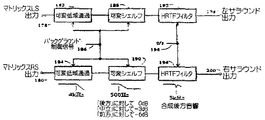
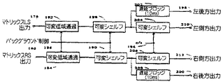
【請求項3】 規定された態様で前記出力の周波数応答および位相応答を変化させるように、前記左のサラウンド出力と前記右のサラウンド出力との後に周波数依存可変フィルタ手段を更に備え、該変化が、前記左および右の音響入力信号において検出されるサラウンドまたはバックグラウンドのアンビエンス成分の存在に応答する多くの制御信号により制御される、請求項2記載のデコーダ。
【請求項4】 規定された態様で前記幾つかの出力の周波数応答および位相応答を変化させるように、前記左および右のサラウンド出力の後に、各々の該サラウンド出力から側方および後方の出力チャネルを提供するに周波数依存可変フィルタ手段と付加的な遅延手段とを更に備え、該変化が、前記左および右の音響入力信号において検出されるサラウンドまたはバックグラウンドのアンビエンス成分の存在に応答する多くの制御信号により制御される、請求項2記載のデコーダ。
【請求項5】 前記制御信号が、
前記左および右の音響入力信号に含まれるサラウンド信号成分または反対位相の信号成分に対する同位相の中央の信号成分の比に応答する中央−サラウンド制御信号と、
強くステアリングされた信号が存在しない期間中に該左および右の音響入力信号に含まれる反対位相の信号成分の存在に応答するバックグラウンド制御信号と、である、請求項3または4に記載のデコーダ。
【請求項6】 少なくとも2つの異なる動作モードが提供され、該マトリックス係数が前記ステアリング信号により該異なる動作モードにおいて異なって制御される請求項1から4のいずれか一項に記載のデコーダ。
【請求項7】 フィルム動作モードが、フィルムのサウンドトラックおよび他のビデオ・ソースから導出されるサラウンドエンコード音響信号の再生のために最適化され、音楽動作モードが音楽レコーディングまたは放送の再生のために最適化される請求項6記載のデコーダ。
【請求項8】 フィルム・ソースをデコードするのために、前記左および右前方の出力に対する前記マトリックス値が前記入力信号の中央の成分をできるだけ多く除去するように構成され、中央の出力の減衰が以前の標準的デコーダよりも少なくとも4dBより大きく開始し、かつ、前記中央/サラウンドステアリング信号が更に正になるとき急速に低減するように、該中央の出力に対する前記マトリックス値が構成され、前記デコーダの該出力において同一である該入力信号の相関されない成分に対する該中央の成分の出力比を保持する要件によって、中間マトリックス値が決定される請求項7記載のデコーダ。
【請求項9】 音楽ソースをデコードするために、中央の減衰が標準的デコーダより少なくとも4dBより大きく開始し、かつ標準的デコーダに対する最大値まで徐々に低減し、値は、約20度の中央/サラウンドステアリング信号値において達し、それから、該減衰はステアリング値が増加するとき比較的一定な状態を保持するように、前記中央の出力に対するマトリックス値が構成され、前記入力信号の中央の成分がこれらの出力から最大限に除去されないが、該入力信号の相関されない成分に対する前記中央の成分の出力比を前記デコーダの出力において保持するために慎重に調整されるように前記左および右前方のマトリックス値が構成され、中央および左および右前方の要素の動作は、該中央の出力と該左または右のいずれかの前方の出力との間に約6dBのレベル差を結果として生じる該中央/サラウンドステアリング値において追加的に制限される、請求項7記載のデコーダ。
【請求項10】 左後方向と右後方向との間に方向が存在するように、左および右前方のマトリックス要素が、後方ヘエンコードされた入力信号が前記前方の出力からは出力を生成しないように構成される、請求項1記載のデコーダ。
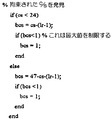
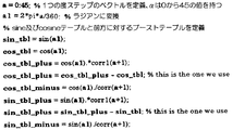
【請求項11】 正味の左/右の成分を含まないが、約22度の中央/サラウンドステアリング値を含む信号に対して約3dBのレベルのブーストがあるように、前記左および右の前方のマトリックス要素が構成され、該中央/サラウンドステアリング値がゼロまで低減するとき、該レベルのブーストはゼロまで低減し、または左/右のステアリング値がゼロから±45度まで増加するとき、該レベルのブーストは45度まで増加する、請求項1記載のデコーダ。
【請求項12】 入力素材における複数の音符、または複数の音節の間のバックグラウンド音響の方向を検出することによりバックグラウンド制御信号を生成する更なる回路を更に備え、該バックグラウンド制御信号は、中央−サラウンドステアリング信号が負であるとき、該中央−サラウンドステアリング信号の値へ急速に設定され、複数の音符と複数の音節との間の該バックグラウンド音響の方向が前方向であるとき、該バックグラウンド制御信号が緩やかに正へ設定され、該バックグラウンド制御信号は、サラウンドエンコード素材が演奏されるときは負の値を保持する傾向があり、標準的な2チャネル素材が演奏されるときは正またはゼロの値を保持する傾向がある、請求項3または4に記載のデコーダ。
【請求項13】 前記バックグラウンド制御信号は、複数の音符の間のバックグラウンドが方向において中立または正のいずれかであるとき、後方の出力のラウドネスが低減されるように、前記前方の出力および後方の出力の相対的ラウドネスを制御するように用いられる、請求項12記載のデコーダ。
【請求項14】 前記バックグラウンド方向信号が正またはゼロであるとき、カットオフ周波数がユーザ調整可能な値へ設定されるように、かつ、該バックグラウンド方向信号が負であるとき、高い値へ上昇するように、該バックグラウンド制御信号が前記後方の出力における可変低域通過フィルタを制御し、これにより通常の2チャネル素材が演奏されるときは前記サラウンド出力がより妨害しないようにする、請求項12記載のデコーダ。
【請求項15】 前記バックグラウンド制御信号が正またはゼロであるとき前記後方の出力における500Hzより高い周波数がユーザ調整可能な値分だけ減衰するように、かつ、該バックグラウンド制御信号が負であるときこの減衰がゼロまで低減されるように、該バックグラウンド制御信号が可変シェルフ・フィルタを制御し、これにより通常の2チャネル素材が演奏されるとき前記サラウンド出力がより妨害しないようにする、請求項12記載のデコーダ。
【請求項16】 前記マトリックスの後方の出力が、該後方の出力における更なる遅延と側方出力における可変低域通過フィルタとの組み合わせにより該側方出力と該後方の出力とに分けられ、該低域通過フィルタは、前記中央−サラウンドステアリング信号が−22度より更に正であるとき高周波へ設定され、該中央−サラウンドステアリング信号が−22度より更に負であるときは、該中央−サラウンドステアリング信号がその最小値の−45度に達するとき、該低域通過周波数が500Hzの最終値まで急速に低減される、請求項5記載のデコーダ。
【請求項17】 前記中央−サラウンドステアリング信号がゼロまたは正であるとき可変フィルタがその最大効果を持つように、かつ、該中央/サラウンドステアリング信号がゼロから−15度まで変化するとき、フィルタ動作がゼロまで低減されるように、かつ、該中央−サラウンドステアリングが更に負になるとき、該フィルタが再び最大限に動作し、次いで該中央−サラウンドステアリング信号がその最小値の−45度に達するとき完全なる後方への音源に対する人間の頭部/耳介システムの周波数応答に僅かに対応するためにそれ自体を修正するように、5チャネル・バージョン・デコーダの前記左および右のサラウンド出力が、前方からの方位における150度より大きい音源に対する該人間の頭部/耳介システムの周波数応答をエミュレートする可変フィルタにより更に供給される、請求項4記載のデコーダ。
【請求項18】 入力信号におけるエネルギ比が出力信号に保持されるように、該出力信号における異なる成分の位相および振幅の関係において該入力信号の方向が保持されるように、かつ、入力信号が任意の入力チャネルから他の任意の入力チャネルヘパンされるとき該出力信号の位相/振幅の関係が請求項1記載のデコーダを介して元の方向にできるだけ近くデコードするように、また標準的フィルム・デコーダを介してデコードされるとき該元の方向にできるだけ近くエンコードするように、音響入力信号の5チャネルを2出力チャネルへ自動的にミックスするエンコーダ回路であって、
左、中央、右、左のサラウンドおよび右のサラウンドとしてそれぞれ識別される該5つの音響
入力信号を受け取る5つの入力端子と、
それぞれが該2つの出力チャネルの1つを外部装置へ提供する2つの出力端子と、
該5つの音響入力信号の幾つかの信号の間の振幅/位相の関係を決定して、そこから制御信号を生成する手段と、
各々の前記入力チャネルの固定比率または可変比率のいずれかを該2つの出力チャネルへミックスする手段と
を備え、該可変比率は該制御信号に応答する、エンコーダ回路。
【請求項19】 同一の入力信号が同位相あるいは反対位相のいずれかの後方の入力へ与えられるとき、出力信号のエネルギが入力信号のエネルギと一致するように、ミキンシング値をアクティブに補正する手段をさらに含む、請求項18記載のエンコーダ。
【請求項20】 複数の音響入力信号を複数の音響出力信号にデコードするためのデコーダであって、
該オーディオ入力信号と通信しているステアリング信号論理であって、複数のステアリング信号を生成する、ステアリング信号論理と、
マトリックス係数を含む少なくとも1つのマトリックスであって、該ステアリング信号論理および該音響入力信号と通信しており、かつ、該音響入力信号と該マトリックス係数を組み合わせて、複数の信号を生成する、少なくとも1つのマトリックスと
を含み、
該複数の信号が組み合わせられて、該出力信号を生成するとき、該音響出力信号における全出力は、該音響入力信号の全出力に実質的に等しい、デコーダ。
【請求項21】 前記マトリックスと通信している加算器であって、前記複数の信号を組合させて、前記音響出力信号を生成する、加算器をさらに含む、請求項20に記載のデコーダ。
【請求項22】 複数の音響入力信号を複数の音響出力信号にデコードするためのデコーダであって、ステアリング信号を生成し、かつ、
該ステアリング信号の関数として該音響出力信号を生成する、論理を含み、該音響出力信号における全出力は、該音響入力信号の全出力に実質的に等しい、デコーダ。
【請求項23】 前記音響出力信号を生成する論理は、前記ステアリング信号の関数としての信号を生成する論理を含み、該ステアリング信号は組み合わせられて、該音響出力信号を生成する、請求項22に記載のデコーダ。
【請求項24】 右の入力信号および左の入力信号を含む音響入力信号を音響出力信号にデコードするためのデコーダであって、該音響出力信号は、非ステアリング成分、方向性成分、左前方の出力信号および右前方の出力信号を含み、該デコーダは、
該音響入力信号と通信しているステアリング信号論理であって、該音響出力信号の方向を定義する複数のステアリング信号を生成するステアリング信号論理と、
マトリックス係数を含む少なくとも1つのマトリックスであって、該ステアリング信号論理と該音響入力信号と通信しており、かつ、該音響入力信号を該マトリックス係数と組み合わせて複数の信号を生成し、該複数の信号は組み合わせられて該出力信号を生成する、少なくとも1つのマトリックスと
を含み、該複数の信号は、組み合わせられて該音響入力信号を生成し、
該マトリックス係数の少なくとも1つのサブセットは、該ステアリング信号の関数であり、方向が前方向であるとき、該ステアリング信号は、該左前方および該右前方の出力信号における該非ステアリング成分を分離し、該方向性成分を局所化し、かつ、該右の入力信号および該左の入力信号との間の電力平衡および該左前方の出力信号と該右前方の出力信号との間の電力平衡を実質的に保つ、デコーダ。
【請求項25】 前記音響出力信号は、中央の出力信号をさらに含み、方向が前方向であるとき、前記マトリックス係数のサブセットは、該中央の信号を低減して、前記左前方および前記右前方の出力信号において生成された前記非ステアリング成分を分離し、該前方向がさらに前方向になるとき、該マトリックス係数のサブセットは該中央の出力信号を増加して、前記方向性成分を局所化する、請求項24に記載のデコーダ。
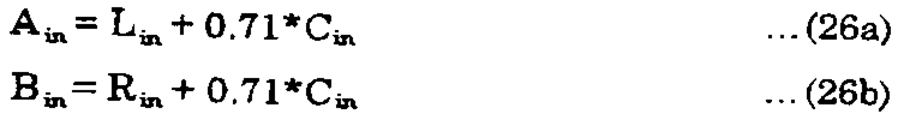
【請求項26】 前記音響入力信号は、中央の成分を含み、前記マトリックス係数のサブセットは、左前方のマトリックス係数および右前方のマトリックス係数を含み、該左前方のマトリックス係数および該右前方のマトリックス係数は、前記左前方および前記右前方の出力信号における該中央の成分を低減する、請求項25に記載のデコーダ。
【請求項27】 前記マトリックス係数のサブセットは、前記音響出力信号における前記音響入力信号の全出力を維持するように、前記中央の出力信号を増加する、請求項26に記載のデコーダ。
【請求項28】 前記マトリックス係数のサブセットは、前記音響出力信号における前記音響入力信号の全出力を維持するように、前記中央の出力信号を増加し、前記左前方、前記右前方および前記中央の出力信号がレベルにおいて実質的に等しい、請求項27に記載のデコーダ。
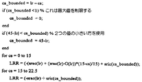
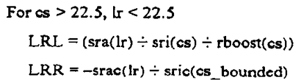
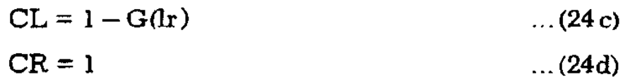
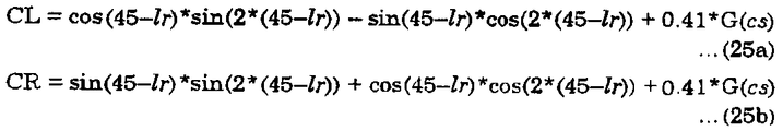
【請求項29】 前記前方向が約0度から約22.5度であるとき、前記マトリックス係数のサブセットは、第1の量分だけ前記中央の出力信号を増加し、該前方向が約22.5度から約45であるとき、第2の量分だけ該中央の信号を増加する、請求項25に記載のデコーダ。
【請求項30】 前記マトリックス係数のサブセットは、前記ステアリング信号によって定義される複数の軸を含む表面を定義し、かつ、前記方向性成分を局所化する該複数の軸のうちの1つに沿ってブーストを定義する、請求項24に記載のデコーダ。
【請求項31】 前記ステアリング信号は、中央−サラウンドステアリング信号を含み、前記ブーストは、該中央−サラウンドステアリング信号によって定義される前記軸に沿う、請求項30に記載のデコーダ。
【請求項32】 前記音響入力信号は、中央の成分を含み、前記マトリックス係数のサブセットは、左前方のマトリックス係数および右前方のマトリックス係数を含み、該左前方のマトリックス係数および該右前方のマトリックス係数は、前記左前方および右前方の出力信号における該中央の成分を低減する、請求項31に記載のデコーダ。
【請求項33】 前記ブーストは、前記音響出力信号における前記音響入力信号の全出力を維持する、請求項32に記載のデコーダ。
【請求項34】 複数の音響入力信号を、非ステアリング成分を含む複数の音響出力信号にデコードするためのデコーダであって、
該複数の音響入力信号通信しているステアリング信号論理であって、複数のステアリング信号を生成する、ステアリング信号論理と、
マトリックス係数を含む少なくとも1つのマトリックスであって、該ステアリング信号論理と該音響入力信号と通信しており、かつ、該音響入力信号を該マトリックス係数と組み合わせて複数の信号を生成し、該複数の信号は組み合わせられて該音響入力信号を生成する、少なくとも1つのマトリックスと
を含み、
該出力信号の該非ステアリング成分が該ステアリング信号と独立である一定のレベルであるように、該信号を生成する該マトリックス係数の少なくとも幾つかは該ステアリング信号の関数である、デコーダ。
【請求項35】 複数の音響入力信号を、非ステアリング信号を含む複数の音響出力信号にデコードするためのデコーダであって、
ステアリング信号を生成し、
該出力信号の該非ステアリング信号が該ステアリング信号とは独立である一定のレベルであるように、該ステアリング信号の関数として該音響出力信号を生成する論理を含む、デコーダ。
【請求項36】 前記音響出力信号を生成する論理は、前記ステアリング信号の関数として信号を生成する論理を含み、該信号は組み合わせられて、該音響出力信号を生成する、請求項35に記載のデコーダ。
【請求項37】 複数の音響入力信号を、前方の出力信号を含む複数の音響出力信号にデコードするためのデコーダであって、
該複数の音響入力信号と通信しているステアリング信号論理であって、方向を定義する複数のステアリング信号を生成する、ステアリング信号論理と、
マトリックス係数を含む少なくとも1つのマトリックスであって、該ステアリング信号論理と該音響入力信号と通信しており、かつ、該音響入力信号を該マトリックス係数と組み合わせて、複数の信号を生成し、該複数の信号は組み合わせられて該音響出力信号を生成する、少なくとも1つのマトリックスと
を含み、
該マトリックス係数のサブセットは、該ステアリング信号の関数であり、方向がおよそ後ろ方向であるとき、該関数は該前方の出力信号をおよそゼロと等しくする、デコーダ。
【請求項38】 前記後ろ方向は、左後方向および右後方向を含み、該方向がおよそ該左後方向からおよそ該右後方向であるとき、前記マトリックス係数のサブセットは前記前方の出力信号をおよそゼロと等しくする、請求項37に記載のデコーダ。
【請求項39】 前記マトリックス係数のサブセットは、左前方のマトリックス係数および右前方のマトリックス係数を含み、前記ステアリング信号によって定義される複数の軸を含む表面を定義し、かつ、方向がおよそ前記後ろ方向であるとき、前記前方の出力信号をおよそゼロに等しくする該複数の軸のうちの1つに沿うカットを含む、請求項37に記載のデコーダ。
【請求項40】 前記ステアリング信号は、中央−サラウンドステアリング信号を含み、前記マトリックス係数のサブセットは、該中央−サラウンドステアリング信号によって定義される軸にそって前記カットを含む、請求項39に記載のデコーダ。
【請求項41】 前記音響入力信号は、方向性成分、非ステアリング成分および、該方向性成分と該非ステアリング成分との間の電力平衡を含み、前記マトリックス係数は、前記ステアリング信号の関数である後方のマトリックス係数を含み、該関数は前記音響出力信号における電力平衡を維持する、請求項37に記載のデコーダ。
【請求項42】 マトリックス要素は、前記ステアリング信号の関数として表面を定義し、該表面は、四分円を含み、かつ、該四分円の中で実質的に連続している、請求項37に記載のデコーダ。
【請求項43】 複数音響入力信号を、複数の前方の出力信号を含む複数の音響入力信号にデコードするためのデコーダであって、
ステアリング信号を生成し、
方向がおよそ後ろ方向であるとき、該前方の出力信号がおよそゼロに等しくなるように、該ステアリング信号の関数として該音響出力信号を生成する論理を含む、デコーダ。
【請求項44】 前記音響出力信号を生成する論理は、前記ステアリング信号の関数として信号を生成する論理を含み、該信号が組み合わせられて、該音響出力信号を生成する、請求項43に記載のデコーダ。
【請求項45】 複数の音響入力信号を複数の音響出力信号にデコードするためのデコーダであって、
該複数の音響入力信号と通信しているステアリング信号論理であって、複数のステアリング信号を生成する、ステアリング信号論理と、
マトリックス係数を含む少なくとも1つのマトリックスであって、該ステアリング信号論理と該音響入力信号と通信しており、かつ、該音響入力信号を該マトリックス係数と組み合わせて複数の信号を生成し、該信号は組み合わせられて該音響出力信号を生成する、少なくとも1つのマトリックスと
を含み、
該マトリックス係数が該ステアリング信号の関数であり、かつ、表面を定義し、該表面は該ステアリング信号によって定義される四分円を含み、かつ、該四分円に渡り実質的に連続している、デコーダ。
【請求項46】 前記マトリックス係数は、前記表面を定義する後方のマトリックス係数を含む、請求項45に記載のデコーダ。
[Claim of claim]
1. A pair of lefts including a directionally encoded component and a non-directional componentandMultiple output channels for reproducing the right audio input signal through loudspeakers surrounding the listening areaToA surround sound decoder for redistributing,SaidleftandDetermine the directional content of the right acoustic signalThereAt least left from-RightSteeringSignal and center-SurroundSteeringIn a surround sound decoder comprising means for generating a signal
SaidCorresponding leftandReceive the right audio input signalFollowTake leftandWith the right input terminal,
Left and right delay means for generating left and right acoustic input signals delayed from the left and right acoustic input signals;
Organized in pairsThe multipleA number of multipliers equal in number to twice the number of output channels,The first element of each of the pairs receives the delayed left acoustic signal, the second element receives the delayed right acoustic signal, and each of the plurality of multiplier means receives its input acoustic signal. The signal is multiplied by a variable matrix factor to provide an output signal, the variable matrix factor being controlled by one or both of the steering signals,Multiple multiplier means,
A plurality of addition means, one of the plurality of addition means being for each of the plurality of output channels, each of the plurality of addition means beingA pair ofSaidOf multiplier meansSaidReceive output signalFollowTake it to its outputExceptMultipleOut ofForce signalOur houseOneGenerate multipleMeans of adding numbers and
Equipped with
The steering signalRegardless of whether the non-directional signal leftandRight channel componentWithwhilesohighSeparation, And whether or not the intended direction exists, regardless of whether or not a directionally encoded signal is present.TheseIn the intended direction while keeping the loudness effectively defined as the total sound output level of the non-directional signal regardless of the directionThemDirect to playbackInReduce the directionally encoded sound component in the uninvolved output, in the intended directionThemDirect to playbackInDirectionally encoded acoustic components at the output involvedenhancementAnd having the variable matrix values configured to maintain a constant full power for such signal,Surround sound decoder.
[Claim 2] SaidMultipleOut ofForce channel is left front, center, right front, leftofSurround and rightofFive identified as surround,Claim 1TheCoder.
[Claim 3] SpecifiedAspectsoSaidTo change the frequency response and phase response of the output,SaidleftTheWith round outputSaidrightTheAfter the round outputFrequency dependent variable filter meansIn addition,The changeBut the leftandSurround detected in the right audio input signalOrRespond to the presence of background ambience componentsManyControl according to the control signal ofTheCoder.
[Claim 4] SpecifiedAspectsoSaidTo change the frequency response and phase response of some outputs,Provide side and rear output channels from each of the surround outputs after the left and right surround outputsFrequencyNumber dependentFurther comprising variable filter means and additional delay means,The changeBut the leftandSurround detected in the right audio input signalOrRespond to the presence of background ambience componentsManyControl according to the control signal ofTheCoder.
5. The control signal comprises:
SaidleftandSurround signal component included in the right audio input signalOrMiddle of same phase for opposite phase signal componentsofCenter in response to the ratio of signal components-Surround control signal,
stronglySteeringDuring the absence of theSaidleftandA background control signal responsive to the presence of an antiphase signal component contained in the right acoustic input signal,Claim 3 orTo 4DescriptionTheCoder.
6. At least two different operating modes are provided:SaidMatrix coefficients areSteeringBy signalSaidDifferent in
7. Film operating mode from film soundtrack and other video sourcesDerivedSurroundEncodingOptimized for playback of sound signal, music operation mode is music recordingOr7. The method according to
8. A film sourceTheDekoDoforTo the aboveleftAnd right frontPeopleofFor the outputSaidMatrix value isSaidCenter of input signalofConfigured to remove as much of the component as possible,ofAttenuation of output is at least 4 dB over previous standard decodersThanStart big,And, SaidDuring ~Central /SurroundSteeringSuddenly when the signal becomes more positiveSpeedTo reduceSaidCenterofFor the outputSaidMatrix values are constructed,SaidOf the decoderSaidOn the outputThe sameOf the input signalcorrelationFor the component that is notSaidCenterof8. The method according to claim 7, wherein the intermediate matrix value is determined by the requirement to hold the output ratio of the components.TheCoder.
9. A music sourceTheDekoTo, Center attenuation at least 4 dB more than standard decoderThanStart large and gradually reduce to the maximum value for the standard decoder,value is,Within about 20 degreesCentral /SurroundSteeringReaching at the signal value,then,The attenuation isSteeringAs the value is kept relatively constant as it increasesSaidCenterofMatrix values for the output are constructed, Said inputCenter of force signalofIngredient istheseMaximum from outputToNot removed,SaidFor uncorrelated components of the input signalSaidCenterofOutput ratio of the componentsSaidAt the output of the decoderLeaveHoldCarefullyTo be adjustedSaidleftAnd right frontPeopleofMatrix values are constructed, center and leftAnd right frontPeopleofThe behavior of the element isSaidCenterofOutput andSaidleftOrrightofEitherKanoForwardofResulting in a level difference of approximately 6 dB with the outputInsideCentral / surroundSteeringIn the valueAdditionalThe method according to claim 7, which is limited toTheCoder.
10. A left direction such that a direction exists between the left rear direction and the right rear directionAnd right frontPeopleofThe matrix element has an input signal that is encoded backwardsSaidForwardofOutput from the outputDo not generateThe decoder of
11. Net left / rightofContains no components, but about 22 degrees center / surroundSteeringvalueTheAbout 3 dB of boost to the included signalAs there is,SaidleftandRight forwardofMatrix elements are constructed,SaidCenter / surroundSteeringWhen the value decreases to zero,SaidLevel boostIsReduce to zero,OrLeft / rightSteeringWhen the value increases from zero to ± 45 degrees,SaidLevel boostIsIncrease to 45 degrees,Claim 1TheCoder.
[12] in the input materialpluralnoteOr moresyllableofAnd further circuitry for generating a background control signal by detecting the direction of the background sound betweenSaidBackground control signal is in the middle-SurroundSteeringWhen the signal is negativeSaidCenter-surroundSteeringQuickly set to the value of the signal,pluralWith notespluralsyllableBetweenWhen the direction of the background sound is forward,SaidBackground control signal is slowly set to positive,Background control signals hold negative values when surround encoded material is playedTend toHolds positive or zero values when standard two-channel material is playedTend toClaim3OrTo 4DescriptionTheCoder.
13. The background control signal is:pluralnoteofBackground between is neutral in directionOrPositiveAny ofBack whenofSo that the loudness of the output is reducedSaidForwardofoutputandBackwardofOutof powerControl relative loudnesslike13. Use according to
14. The background direction signal is positiveOrWhen it is zero,So that the cutoff frequency is set to a user adjustable value, and,When the background direction signal is negative,To rise to a high value,SaidBackground control signalSaidBackwardofControl a variable low pass filter at the output so that when normal two channel material is playedSaidSurround outputDoes not disturb moreTo do,Claim 12.TheCoder.
[15] SaidWhen the background control signal is positive or zeroSaidBackwardofUser adjustable values above 500 Hz at the outputMinutesOnly to attenuate, and,When the background control signal is negativethisSo that the attenuation is reduced to zeroSaidA background control signal controls the variable shelf filter, which causes normal two-channel material to be playedSaidSurround outputDoes not disturb moreTo do,Claim 12.TheCoder.
[16] SaidmatrixAfterPeopleofThe output isSaidBackwardofBy combining an additional delay at the output and a variable low pass filter at the side outputSaidWith side outputSaidBackwardofDivided into output andSaidThe low pass filter is-SurroundSteeringSignal is more than -22 degreesPositiveWhen it is set to high frequency,SaidCenter-SurroundSteeringSignal is more negative than -22 degreesIswhen,SaidCenter-SurroundSteeringThe signal isAt its minimum valueWhen reaching -45 degrees,Low pass frequency jumps to the final value of 500 HzSpeedReduced to,Claim 5 statementTheCoder.
17. The center-SurroundSteeringSignal is zeroOrWhen positive the variable filter is at its maximumeffectTo have,Center / surroundSteeringWhen the signal changes from zero to -15 degrees,So that the filter action is reduced to zero, and,Center-SurroundSteeringWhen becomes even more negative,The filter works again maximally and thenSaidCenter-surroundSteeringSignal is at its minimum valueofComplete when reaching -45 degreesBecomeBackwardToSlightly corresponds to the frequency response of the human head / earpin system to the sound sourcefor5-channel version decoder to correct itselfSaidleftandThe right surround output is for a sound source greater than 150 degrees in the heading from the frontSaidFurther supplied by a variable filter that emulates the frequency response of the human head / earpin system,Claim 4 statementTheCoder.
18. The energy ratio in the input signal is held in the output signalSaidIn terms of the phase and amplitude of the different components in the output signalSaidSo that the direction of the input signal is maintained, and,Input signal from any input channelotherAnyEntry ofWhen the power channel is pannedSaidThe decoder according to
Left, center, right, leftofSurround and rightofEach identified as surroundSaid5 sounds
Receive input signalFollowWith five input terminals to take,
Each oneTwo output terminals providing one of the two output channels to an external device;
SaidSome of the five acoustic input signalsofDetermine the amplitude / phase relationship betweenThereControl signal fromGenerateMeans,
EachOf the input channelFixedratioOr means for mixing either of the variable ratios into the two output channels
And the variable ratio isRespond to control signals, DEncoder circuit.
[19] SameInput signal in phase or out of phaseeitherBehindofTo inputGivenWhen,The energy of the output signal is the energy of the input signalMatchAs a means to actively correct the mixing valuefurtherThe encoder according to claim 18, comprising.
[20] A decoder for decoding a plurality of acoustic input signals into a plurality of acoustic output signals, the decoder comprising:
Steering signal logic in communication with the audio input signal, the steering signal logic generating a plurality of steering signals;
At least one matrix including matrix coefficients in communication with the steering signal logic and the acoustic input signal, and combining the acoustic input signal with the matrix coefficients to generate a plurality of signals With one matrix
Including
A decoder, wherein when the plurality of signals are combined to generate the output signal, the total output in the audio output signal is substantially equal to the total output of the audio input signal.
21. 21. The decoder of
22. A decoder for decoding a plurality of acoustic input signals into a plurality of acoustic output signals, the steering signal being generated, and
A decoder for generating the acoustic output signal as a function of the steering signal, wherein all outputs in the acoustic output signal are substantially equal to all outputs of the acoustic input signal.
[23] 23. The decoder of claim 22, wherein the logic that generates the acoustic output signal comprises logic that generates a signal as a function of the steering signal, the steering signals being combined to generate the acoustic output signal.
[24] A decoder for decoding an acoustic input signal comprising an input signal on the right and an input signal on the left into an acoustic output signal, the acoustic output signal comprising a non-steer component, a directional component, an output signal on the left front and a right front The output signal of the
Steering signal logic in communication with the audio input signal, the steering signal logic generating a plurality of steering signals defining a direction of the audio output signal;
At least one matrix including matrix coefficients in communication with the steering signal logic and the acoustic input signal, and combining the acoustic input signal with the matrix coefficients to generate a plurality of signals; The signals are combined to produce the output signal, at least one matrix and
The plurality of signals are combined to produce the acoustic input signal,
The steering signal separates the non-steering components in the left front and the right front output signals when at least one subset of the matrix coefficients is a function of the steering signal and the direction is forward. Localizing a directional component and substantially equalizing power balance between the right input signal and the left input signal and power balance between the left front output signal and the right front output signal Keep, decoder.
[25] The acoustic output signal further includes a central output signal, and when the direction is forward, a subset of the matrix coefficients reduce the central signal and generate at the left front and the right front output signals 25. The method according to
[26] The acoustic input signal includes central components, and the subset of matrix coefficients includes left front matrix coefficients and right front matrix coefficients, and the left front matrix coefficients and the right front matrix coefficients are the left 26. The decoder of claim 25, wherein the center component in the forward and forward right output signals is reduced.
[27] 27. The decoder of claim 26, wherein the subset of matrix coefficients increase the central output signal to maintain full output of the acoustic input signal in the acoustic output signal.
[28] The subset of matrix coefficients increments the central output signal to maintain full power of the acoustic input signal in the acoustic output signal, the left front, the right front and the center output signal being at a
29. The subset of matrix coefficients increase the central output signal by a first amount when the forward direction is about 0 degrees to about 22.5 degrees, and the forward direction is about 22.5 degrees to about 22.5 degrees. 26. The decoder of claim 25, wherein when it is 45, the central signal is increased by a second amount.
[30] The subset of matrix coefficients define a surface including a plurality of axes defined by the steering signal and define a boost along one of the plurality of axes localizing the directional component 25. The decoder of
31. 31. The decoder of
32. The acoustic input signal includes central components, and the subset of matrix coefficients includes left front matrix coefficients and right front matrix coefficients, and the left front matrix coefficients and the right front matrix coefficients are the left 32. The decoder of claim 31, wherein the center component in the front and right front output signals is reduced.
[33] 33. The decoder of
[34] A decoder for decoding a plurality of acoustic input signals into a plurality of acoustic output signals including non-steering components, the decoder comprising:
Steering signal logic in communication with the plurality of acoustic input signals, the steering signal logic generating a plurality of steering signals;
At least one matrix including matrix coefficients in communication with the steering signal logic and the acoustic input signal, and combining the acoustic input signal with the matrix coefficients to generate a plurality of signals; The signals are combined to produce the acoustic input signal, at least one matrix and
Including
A decoder, wherein at least some of the matrix coefficients that produce the signal are a function of the steering signal, such that the non-steering component of the output signal is at a constant level that is independent of the steering signal.
[35] A decoder for decoding a plurality of acoustic input signals into a plurality of acoustic output signals, including non-steering signals,
Generate a steering signal,
A decoder including logic to generate the acoustic output signal as a function of the steering signal such that the non-steering signal of the output signal is at a constant level independent of the steering signal.
[36] 36. The decoder of claim 35, wherein the logic that generates the acoustic output signal comprises logic that generates a signal as a function of the steering signal, the signals being combined to generate the acoustic output signal.
[37] A decoder for decoding a plurality of acoustic input signals into a plurality of acoustic output signals including a forward output signal, the decoder comprising:
Steering signal logic in communication with the plurality of acoustic input signals, the steering signal logic generating a plurality of steering signals defining a direction;
At least one matrix including matrix coefficients in communication with the steering signal logic and the acoustic input signal, and combining the acoustic input signal with the matrix coefficients to generate a plurality of signals; Signals are combined to produce the acoustic output signal, at least one matrix and
Including
A decoder, wherein the subset of matrix coefficients is a function of the steering signal, and when the direction is approximately backward, the function equalizes the forward output signal to approximately zero.
[38] The back direction includes a left back direction and a right back direction, the subset of matrix coefficients equaling the front output signal to approximately zero when the direction is approximately from the left back direction to the right back direction The decoder according to claim 37.
[39] The subset of matrix coefficients includes a left front matrix coefficient and a right front matrix coefficient, defining a surface including a plurality of axes defined by the steering signal, and when a direction is approximately the back direction, 39. The decoder of claim 37, comprising a cut along one of the plurality of axes that makes the forward output signal approximately equal to zero.
40. 40. The decoder of claim 39, wherein the steering signal comprises a center-surround steering signal, and wherein the subset of matrix coefficients comprises the cuts along an axis defined by the center-surround steering signal.
41. The acoustic input signal includes a directional component, a non-steer component, and a power balance between the directional component and the non-steer component, and the matrix coefficient includes a rear matrix coefficient that is a function of the steering signal. 38. The decoder of claim 37, wherein the function maintains power balance in the acoustic output signal.
[42] The decoder according to claim 37, wherein a matrix element defines a surface as a function of the steering signal, the surface comprising quadrants and being substantially continuous in the quadrants.
[43] A decoder for decoding a plurality of acoustic input signals into a plurality of acoustic input signals including a plurality of forward output signals, the decoder comprising:
Generate a steering signal,
A decoder comprising logic to generate the acoustic output signal as a function of the steering signal such that the forward output signal is approximately equal to zero when the direction is approximately backward.
[44] 44. The decoder of claim 43, wherein the logic that generates the acoustic output signal comprises logic that generates a signal as a function of the steering signal, the signals being combined to generate the acoustic output signal.
[45] A decoder for decoding a plurality of acoustic input signals into a plurality of acoustic output signals, the decoder comprising:
Steering signal logic in communication with the plurality of acoustic input signals, the steering signal logic generating a plurality of steering signals;
At least one matrix including matrix coefficients in communication with the steering signal logic and the acoustic input signal, and combining the acoustic input signal with the matrix coefficients to generate a plurality of signals, the signals being At least one matrix in combination to generate the acoustic output signal
Including
The matrix coefficient is a function of the steering signal and defines a surface, the surface includes a quadrant defined by the steering signal and is substantially continuous across the quadrant ,decoder.
[46] 46. The decoder of
Claims (23)
対応する前記左右の音響入力信号を受取る左右の入力端子と、
前記左右の音響入力信号から遅延した左右の音響信号を生じる左右の遅延手段と、
第1の要素が遅延された左の前記音響信号を受取り第2の要素が遅延された右の音響信号を受取る、第1の要素と第2の要素からなる対に構成された前記出力チャネル数の2倍に等しい数の、前記指向信号の一方または両方により制御される可変マトリックス係数で入力音響信号を乗じて出力信号を生じる複数の乗算器手段と、
各々が1対の前記乗算器手段の出力信号を受取りその出力に複数の前記出力信号の1つを生じる、複数の前記出力チャネルのそれぞれに1つずつの複数の加算手段と、
を備え、
意図された方向における再生に直接関与しない出力における方向的に符号化された音響成分を低減し、意図された方向における再生に直接関与する出力における方向的に符号化された音響成分を強調し、前記指向出力の如何に拘わらず非方向性信号の左右のチャネル成分間の高い分離を保持し、かつ方向的に符号化された信号が存在するか否かに拘わらず、意図された方向が存在するならばその方向の如何に拘わらず非方向性信号の全音響出力レベルとして定義されるラウドネスを有効に一定に維持しながら、かかる信号に対する一定の全出力を維持するように構成された前記可変マトリックス値を有するサラウンド音響デコーダ。Surround sound that redistributes a pair of left and right acoustic input signals, including a directionally encoded component and a non-directional component, into multiple output channels for reproduction through loudspeakers surrounding the listening area A surround sound decoder comprising a decoder, the means for determining the directional content of the left and right sound signals and generating therefrom at least the left / right directional signals and the center / surround directional signals.
Left and right input terminals for receiving the corresponding left and right sound input signals;
Left and right delay means for producing left and right acoustic signals delayed from the left and right acoustic input signals;
The number of output channels arranged in pairs consisting of a first element and a second element, wherein the first element receives the delayed left acoustic signal and the second element receives the delayed right acoustic signal A plurality of multiplier means, which multiply the input acoustic signal by a variable matrix factor controlled by one or both of said directional signals, by a number equal to twice of to produce an output signal;
A plurality of summing means, one for each of a plurality of said output channels, each receiving an output signal of a pair of said multiplier means and producing one of a plurality of said output signals at its output;
Equipped with
Reduce the directionally encoded sound component at the output not directly involved in the reproduction in the intended direction and emphasize the directionally encoded sound component at the output directly involved in the reproduction in the intended direction, Regardless of the directional output, it maintains high separation between the left and right channel components of the non-directional signal, and the intended direction exists regardless of whether or not a directionally encoded signal is present. Said variable configured to maintain a constant total power for such a signal, while maintaining effectively constant the loudness defined as the total sound power level of the non-directional signal regardless of its direction Surround sound decoder with matrix values.
強く指向された信号が存在しない期間中に左右の前記音響入力信号に含まれる逆位相の信号成分の存在に応答するバックグラウンド制御信号と、
である請求項3または4のいずれかに記載のサラウンド音響デコーダ。A center / surround control signal in which the control signal is responsive to a ratio of an in-phase central signal component to a surround signal component or an anti-phase signal component included in the left and right audio input signals;
A background control signal responsive to the presence of anti-phase signal components contained in the left and right acoustic input signals during a period in which no strongly directed signal is present;
The surround sound decoder according to any one of claims 3 or 4, which is
左、中央、右、左サラウンドおよび右サラウンドとしてそれぞれ識別される5つの音響入力信号を受取る5つの入力端子と、
2つの出力チャネルの1つを外部装置へそれぞれ提供する2つの出力端子と、
前記5つの音響入力信号の幾つかの信号間の振幅/位相の関係を決定してこれから制御信号を生じる手段と、
前記入力チャネルの各々の固定比率あるいは前記制御信号に応答する可変比率のいずれかを前記2出力チャネルの1つへミックスする手段と、
を備えるエンコーダ回路。The direction of the input signal is maintained in relation to the phase and amplitude of the different components in the output signal so that the energy ratio in the input signal is maintained in the output signal, and the input signal is from any input channel to any other So that the phase / amplitude relationship of the output signal when panned to the input channel of the video signal decodes as close as possible to the original direction by the decoder according to claim 1 and in the original direction when decoded by the standard film decoder An encoder circuit that automatically mixes five channels of the acoustic input signal into two output channels so as to decode as close as possible,
5 input terminals for receiving 5 sound input signals identified respectively as left, center, right, left surround and right surround;
Two output terminals, each providing one of the two output channels to an external device;
Means for determining an amplitude / phase relationship between several of the five acoustic input signals and generating a control signal therefrom;
Means for mixing either the fixed ratio of each of the input channels or the variable ratio responsive to the control signal to one of the two output channels;
An encoder circuit comprising:
Applications Claiming Priority (3)
| Application Number | Priority Date | Filing Date | Title |
|---|---|---|---|
| US5816997P | 1997-09-05 | 1997-09-05 | |
| US09/146,442 US6697491B1 (en) | 1996-07-19 | 1998-09-03 | 5-2-5 matrix encoder and decoder system |
| PCT/US1998/018390 WO1999012386A1 (en) | 1997-09-05 | 1998-09-03 | 5-2-5 matrix encoder and decoder system |
Related Child Applications (1)
| Application Number | Title | Priority Date | Filing Date |
|---|---|---|---|
| JP2006149032A Division JP4782614B2 (en) | 1997-09-05 | 2006-05-29 | decoder |
Publications (2)
| Publication Number | Publication Date |
|---|---|
| JP2004507904A JP2004507904A (en) | 2004-03-11 |
| JP2004507904A5 true JP2004507904A5 (en) | 2006-01-12 |
Family
ID=26737320
Family Applications (2)
| Application Number | Title | Priority Date | Filing Date |
|---|---|---|---|
| JP2000509252A Withdrawn JP2004507904A (en) | 1997-09-05 | 1998-09-03 | 5-2-5 matrix encoder and decoder system |
| JP2006149032A Expired - Lifetime JP4782614B2 (en) | 1997-09-05 | 2006-05-29 | decoder |
Family Applications After (1)
| Application Number | Title | Priority Date | Filing Date |
|---|---|---|---|
| JP2006149032A Expired - Lifetime JP4782614B2 (en) | 1997-09-05 | 2006-05-29 | decoder |
Country Status (6)
| Country | Link |
|---|---|
| EP (1) | EP1013140B1 (en) |
| JP (2) | JP2004507904A (en) |
| CN (1) | CN1214690C (en) |
| AU (1) | AU750877C (en) |
| PL (1) | PL338988A1 (en) |
| WO (1) | WO1999012386A1 (en) |
Families Citing this family (21)
| Publication number | Priority date | Publication date | Assignee | Title |
|---|---|---|---|---|
| US6154660A (en) * | 1998-07-21 | 2000-11-28 | Ericsson Inc. | Callee-based telephone line preselection |
| US6442278B1 (en) * | 1999-06-15 | 2002-08-27 | Hearing Enhancement Company, Llc | Voice-to-remaining audio (VRA) interactive center channel downmix |
| KR100923297B1 (en) * | 2002-12-14 | 2009-10-23 | 삼성전자주식회사 | Method for encoding stereo audio, apparatus thereof, method for decoding audio stream and apparatus thereof |
| CN1748247B (en) * | 2003-02-11 | 2011-06-15 | 皇家飞利浦电子股份有限公司 | Audio coding |
| JP3915804B2 (en) * | 2004-08-26 | 2007-05-16 | ヤマハ株式会社 | Audio playback device |
| TWI397903B (en) * | 2005-04-13 | 2013-06-01 | Dolby Lab Licensing Corp | Economical loudness measurement of coded audio |
| WO2006132857A2 (en) * | 2005-06-03 | 2006-12-14 | Dolby Laboratories Licensing Corporation | Apparatus and method for encoding audio signals with decoding instructions |
| CN101233570B (en) * | 2005-07-29 | 2011-06-22 | Lg电子株式会社 | Method for generating encoded audio signal and method for processing audio signal |
| WO2007043388A1 (en) * | 2005-10-07 | 2007-04-19 | Matsushita Electric Industrial Co., Ltd. | Acoustic signal processing device and acoustic signal processing method |
| TWI420918B (en) * | 2005-12-02 | 2013-12-21 | Dolby Lab Licensing Corp | Low-complexity audio matrix decoder |
| KR20080086549A (en) * | 2006-04-03 | 2008-09-25 | 엘지전자 주식회사 | Apparatus for processing media signal and method thereof |
| TWI517562B (en) * | 2006-04-04 | 2016-01-11 | 杜比實驗室特許公司 | Method, apparatus, and computer program for scaling the overall perceived loudness of a multichannel audio signal by a desired amount |
| US8515106B2 (en) | 2007-11-28 | 2013-08-20 | Qualcomm Incorporated | Methods and apparatus for providing an interface to a processing engine that utilizes intelligent audio mixing techniques |
| US8660280B2 (en) * | 2007-11-28 | 2014-02-25 | Qualcomm Incorporated | Methods and apparatus for providing a distinct perceptual location for an audio source within an audio mixture |
| CN102137326B (en) | 2008-04-18 | 2014-03-26 | 杜比实验室特许公司 | Method and apparatus for maintaining speech audibility in multi-channel audio signal |
| PL2154677T3 (en) * | 2008-08-13 | 2013-12-31 | Fraunhofer Ges Forschung | An apparatus for determining a converted spatial audio signal |
| TWI413109B (en) | 2008-10-01 | 2013-10-21 | Dolby Lab Licensing Corp | Decorrelator for upmixing systems |
| KR101600352B1 (en) | 2008-10-30 | 2016-03-07 | 삼성전자주식회사 | / method and apparatus for encoding/decoding multichannel signal |
| CN103000179B (en) * | 2011-09-16 | 2014-11-12 | 中国科学院声学研究所 | Multichannel audio coding/decoding system and method |
| JP6049762B2 (en) | 2012-02-24 | 2016-12-21 | ドルビー・インターナショナル・アーベー | Audio processing |
| CN108206021B (en) * | 2016-12-16 | 2020-12-18 | 南京青衿信息科技有限公司 | Backward compatible three-dimensional sound encoder, decoder and encoding and decoding methods thereof |
Family Cites Families (10)
| Publication number | Priority date | Publication date | Assignee | Title |
|---|---|---|---|---|
| US4152542A (en) * | 1971-10-06 | 1979-05-01 | Cooper Duane P | Multichannel matrix logic and encoding systems |
| JPS5248001B2 (en) * | 1973-08-20 | 1977-12-07 | ||
| US4862502A (en) * | 1988-01-06 | 1989-08-29 | Lexicon, Inc. | Sound reproduction |
| JP2647991B2 (en) * | 1990-04-26 | 1997-08-27 | 三洋電機株式会社 | Audio signal processing device having directionality enhancement |
| US5172415A (en) * | 1990-06-08 | 1992-12-15 | Fosgate James W | Surround processor |
| US5504819A (en) * | 1990-06-08 | 1996-04-02 | Harman International Industries, Inc. | Surround sound processor with improved control voltage generator |
| US5136650A (en) * | 1991-01-09 | 1992-08-04 | Lexicon, Inc. | Sound reproduction |
| GB9103207D0 (en) * | 1991-02-15 | 1991-04-03 | Gerzon Michael A | Stereophonic sound reproduction system |
| JPH0560098U (en) * | 1992-01-09 | 1993-08-06 | 三洋電機株式会社 | Audio signal processor |
| US5796844A (en) * | 1996-07-19 | 1998-08-18 | Lexicon | Multichannel active matrix sound reproduction with maximum lateral separation |
-
1998
- 1998-09-03 WO PCT/US1998/018390 patent/WO1999012386A1/en not_active Application Discontinuation
- 1998-09-03 PL PL98338988A patent/PL338988A1/en unknown
- 1998-09-03 EP EP98945881A patent/EP1013140B1/en not_active Expired - Lifetime
- 1998-09-03 CN CNB988109131A patent/CN1214690C/en not_active Expired - Lifetime
- 1998-09-03 AU AU93026/98A patent/AU750877C/en not_active Ceased
- 1998-09-03 JP JP2000509252A patent/JP2004507904A/en not_active Withdrawn
-
2006
- 2006-05-29 JP JP2006149032A patent/JP4782614B2/en not_active Expired - Lifetime
Similar Documents
| Publication | Publication Date | Title |
|---|---|---|
| JP2004507904A5 (en) | ||
| US5530760A (en) | Apparatus and method for adjusting levels between channels of a sound system | |
| US5870480A (en) | Multichannel active matrix encoder and decoder with maximum lateral separation | |
| EP0923848B1 (en) | Multichannel active matrix sound reproduction with maximum lateral separation | |
| JP2695888B2 (en) | Directional enhancement system for sound reproduction | |
| KR100591008B1 (en) | Multidirectional Audio Decoding | |
| Dressler | Dolby Surround Pro Logic decoder principles of operation | |
| CA2071708C (en) | Audio surround system with stereo enhancement and directivity servos | |
| JP4782614B2 (en) | decoder | |
| US6697491B1 (en) | 5-2-5 matrix encoder and decoder system | |
| US5136650A (en) | Sound reproduction | |
| US7889870B2 (en) | Method and apparatus to simulate 2-channel virtualized sound for multi-channel sound | |
| US8126173B2 (en) | System and method for expanding multi-speaker playback | |
| US5119422A (en) | Optimal sonic separator and multi-channel forward imaging system | |
| WO2012163445A1 (en) | Method for generating a surround audio signal from a mono/stereo audio signal | |
| WO1998033357A2 (en) | Method and apparatus for electronically embedding directional cues in two channels of sound for interactive applications | |
| US6850622B2 (en) | Sound field correction circuit | |
| JPH06165079A (en) | Down mixing device for multichannel stereo use | |
| US6882733B2 (en) | Surround headphone output signal generator | |
| US20090122994A1 (en) | Localization control device, localization control method, localization control program, and computer-readable recording medium | |
| KR100454012B1 (en) | 5-2-5 matrix encoder and decoder system | |
| EP0630168B1 (en) | Improved Dolby prologic decoder | |
| KR0160205B1 (en) | THE DIRECTIONAL EMPHASIS APPARATuS USING A STEREO SIGNAL | |
| JP2006319804A (en) | Digital bass booster and virtual surround decoder | |
| WO2013145156A1 (en) | Audio signal processing device and audio signal processing program |