JP2004503767A - Quasi-static viscometer - Google Patents
Quasi-static viscometer Download PDFInfo
- Publication number
- JP2004503767A JP2004503767A JP2002510912A JP2002510912A JP2004503767A JP 2004503767 A JP2004503767 A JP 2004503767A JP 2002510912 A JP2002510912 A JP 2002510912A JP 2002510912 A JP2002510912 A JP 2002510912A JP 2004503767 A JP2004503767 A JP 2004503767A
- Authority
- JP
- Japan
- Prior art keywords
- viscometer
- fluid
- cavity
- viscosity
- sensor
- Prior art date
- Legal status (The legal status is an assumption and is not a legal conclusion. Google has not performed a legal analysis and makes no representation as to the accuracy of the status listed.)
- Pending
Links
Images


Classifications
-
- G—PHYSICS
- G01—MEASURING; TESTING
- G01N—INVESTIGATING OR ANALYSING MATERIALS BY DETERMINING THEIR CHEMICAL OR PHYSICAL PROPERTIES
- G01N11/00—Investigating flow properties of materials, e.g. viscosity, plasticity; Analysing materials by determining flow properties
- G01N11/02—Investigating flow properties of materials, e.g. viscosity, plasticity; Analysing materials by determining flow properties by measuring flow of the material
- G01N11/04—Investigating flow properties of materials, e.g. viscosity, plasticity; Analysing materials by determining flow properties by measuring flow of the material through a restricted passage, e.g. tube, aperture
- G01N11/08—Investigating flow properties of materials, e.g. viscosity, plasticity; Analysing materials by determining flow properties by measuring flow of the material through a restricted passage, e.g. tube, aperture by measuring pressure required to produce a known flow
-
- G—PHYSICS
- G01—MEASURING; TESTING
- G01N—INVESTIGATING OR ANALYSING MATERIALS BY DETERMINING THEIR CHEMICAL OR PHYSICAL PROPERTIES
- G01N33/00—Investigating or analysing materials by specific methods not covered by groups G01N1/00 - G01N31/00
- G01N33/22—Fuels, explosives
- G01N33/225—Gaseous fuels, e.g. natural gas
Abstract
Description
【0001】
(背景)
本発明は、粘度検出器に関し、詳細にはデルタ圧力に基づくセンサに関する。より詳細には、本発明は、燃焼を目的とするガスまたは液体燃料の酸素消費量(oxygen demand)(完全燃焼の場合)を測定するための粘度センサに関する。
【0002】
既存のおよび最近提案された準静的粘度計はどちらも、流体(すなわちガスまたは液体)密度および圧力に依存し、高価である(振動ワイヤーまたは水晶振動子に基づく粘度計など)。その他の粘度計は、さらなる流体特性の依存性があるという欠点を有し(たとえば熱駆動される毛管フローを伴うもの)、劣化し漏れやすいバルブのせいでドリフトする傾向があるか(加圧ガス源からの周期的な再充填によって駆動される毛管フロー、バルブ閉鎖、および減衰観察に依存する粘度計の場合)、またはその方位に依存する(落球式粘度計の場合)。
【0003】
提案されているセンサは、流体の既知の特性、粘度を測定する。センサを燃焼制御システムに適用すれば、フィード・フォワード(feed−forward)動作および激しくない予燃焼環境での検知が可能になる。センサは、特性が測定データに単純に比例することができるため(1つの好ましい測定アプローチにおいて)、また燃料のウォッベ(Wobbe)数、酸素消費量、または発熱量(heating value)との関係も単純であるため、低コストであり、そのため検知誤差による全体の燃焼制御誤差への寄与は比較的小さい。
【0004】
本発明は、既知の特性である粘度を燃焼制御へと利用または応用することに関する。また本発明は、粘度測定への好ましいアプローチをこの応用に用いることにも関する。
【0005】
粘度ηは、毛管(半径rcおよび長さLc)内の層流容積流量(laminar volumetric flow)(dV/dt)および圧力降下Δpに対する直線関係によって最も良く知られる。これを式(1)に示す。
【0006】
dV/dt=πΔprc 4/(8Lcη) (1)
最初に注意すべきことは、天然ガスの組成がさまざまであるにもかかわらず、その事実を補うように、どんな組成であっても低コストで燃焼させることのできる手段を探す場合に、燃焼制御に対する個別の特性としての粘度の可能性、および、燃焼させずに発熱量を測定する方法であって、k(T1)、k(T2)、およびηを含む相関関係を介した、すなわち他の特性と関連した分析的な測定が含まれる方法に対する個別の特性としての粘度の可能性である。
【0007】
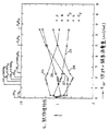
燃料の粘度、また、以前は煙道O2濃度も、燃料の酸素消費量DO2の、予測されるかまたは実際の変化を表示するためのものであった。図1に、η(曲線23)と、燃料ガスの他の熱物理(Qi)特性、すなわちρ、密度(曲線26)、およびk、熱伝導度(曲線24)、およびCp、比熱(曲線25)、およびCv、熱線式風速計(thermal anemometer)の補正因子(曲線27)との間の比較、およびこれらの特性が個別に燃料の酸素消費量、DO2といかに良く相関しているかを図で示す。DO2が増加したとき、cpも有望であるように見えるが、ηが最も都合の良い単調な減少を示す。不燃性CO2のCp値(8.83cal/(mol・K)、H2Oでは8.60である)は、CH4およびC2H6のCp値(8.50および12.42)の間にあるが、不燃性ガスO2、N2、CO2(H2Oを除いて)のη値は全て、CH4のη値を上回っている。
【0008】
2つ以上の燃料特性を、発熱量またはDO2との相関関係に含めることによって、達成可能な精度は著しく増加するが(後で引用する従来技術に注意されたい)、Cpを測定するのにデジタル処理を行なう必要があるためコストも著しく増加するという犠牲を伴う。上述したことは、排気の制御および効率は全ての燃焼制御の最も重要な目標であるという仮定に基づく。この目標に最も近づくには、一定の煙道O2または過剰空気の下で操業する。このような操業は、一定の空気フローを維持し、燃料フローをその組成変動(DO2およびm*を変える)に対応して調整することによって満足される。その濃度変化の半分は、因子mによって処理される。と言うのは、mはオリフィス制御またはベンチュリー制御のフロー制御状況の全てに作用するからである。燃料フローを調整してWb(ウォッベ数)の変動に対抗するという目的は同様であるが、それほどの正確性はなく(A/F(空燃比)および排気を一定に保とうとした場合)、次のようなウォッベ数の定義に戻ることになる。Wb=ΔH/m*、ここでΔH=O2消費量ではなく発熱量であり、m*=(Mgas/Mair)0.5である。Mはモルであり、Wbは、非炭化水素燃料成分たとえばH2およびCOがない限り、Bn(ボンヌ(Bonne)数=D02/m*)と密に連結している。DO2またはBnと粘度との相関関係は、式DO2=A+BηCまたはBn=A’+B’η0.5によって、それぞれ求めることができる。AおよびBは相関係数であり、Cは相関指数である。A’およびB’は同様に相関係数である。相関関係は自然の法則のそれに似ている。関連する情報は、「Microsensors for Fluid Properties」、U.BonneおよびD.Kubisiak著、Scientific Honeyweller、Sensors Issue(1996)の21ページの図6にある。さらなる情報は、米国特許第5,486,107号(U.Bonne、1996年1月23日に付与)の発明名称「Determination of Fuel Characteristics」にある。なおこの文献は、本明細書において参照により取り入れられている。
【0009】
提案する粘度計に基づく燃焼制御システムの意義を説明するために、表1において、熱伝導度センサに基づいた燃焼制御システムの特性と関係のあるいくつかのパラメータを、粘度センサに基づいたシステムの場合に対して比較する。示したように全ての点において、粘度に基づいたシステムの方が、センサ出力の圧力および温度に対する依存性が小さいなどの有利な値を示すが、燃料+空気混合物中の燃料−ガス組成または燃料濃度に対する依存性はより大きい。後者のパラメータは、燃料+空気混合物の熱物理特性を直接測定する利点を定量化するために含めた。示したように、予め混合した燃料+空気混合物の粘度または熱伝導度を測定した場合、圧力、温度、および湿度の影響が、求める燃料特性の影響よりも非常に大きくなる。同様の状況が、煙道ガス中のηまたはkを測定する場合に形成される。
【0010】
表1に、DO2またはλ、波長のセンサとしての熱伝導度に対する粘度の利点を示す。λ=(実際の空燃比)÷(化学量論的空燃比)である。この表によれば、粘度はλおよびD02の変化に対して熱伝導度よりも約2倍敏感であるが、圧力および温度の変動に対しては30%感度が低いことが示される。これは、DO2またはλの測定に対しては、粘度の検出によって熱伝導の場合よりも数倍正確なセンサが得られることを意味する。ガスG20はメタンであり、G271は74%のメタンと26%の窒素からなるガス混合物である。pは圧力(bar)であり、Tは温度(℃)である。Wは、所望の特性(λまたはDO2)を測定する従属変数である。kおよびηの感度は、空気と混合された燃料の窒素含有量、λ、T、p、および純粋燃料ガスの窒素含有量の変動に対するものである。
【0011】
【表1】

最も好ましい特性(kまたはη)に対しては、1〜3列のW値は最も高く4〜5は最も低くなければならない。粘度が好ましい選択であることは明らかである。
【0013】
(発明の概要)
本明細書で開示する粘度計は、加圧ガス、マイクロセンサの入手のしやすさ、または熱駆動装置(thermal driver)に依存せず、その出力は絶対圧力とは無関係である(粘度が無関係である範囲で)。本粘度計は方位の影響を受けず、低コストで製造することができる。本粘度センサは、種々のガス混合物の酸素消費量を測定するために用いられる。本センサは、流体容積の変位装置、アクチュエータまたは駆動装置たとえばスピーカ・メンブレン、および圧力センサまたは検出器たとえばマイクロフォンを、チャンバーまたはキャビティ、およびキャビティと粘度センサの周囲環境との間の制御された漏れ口(leak)とともに有する。駆動装置、漏れ口、およびセンサ・エレクトロニクスは、市販される安価なコンポーネントから組み立てることができる。要約して言えばセンサは、製造コストが低く、精度、信頼性、本質的安全が良好で、耐用寿命が長い。
【0014】
(実施形態の説明)
図2の粘度計10では、圧力差Δpにおける、制御された漏れ口(最初に毛管(C)11(半径rc、長さLcの毛管チューブ11)を選択する)を通る層流容積流量(dV/dt)と粘度ηとの間の直線関係を用いている。これらのパラメータの数学的関係を下式(2)に示す。
【0015】
dV/dt=πΔprc 4/(8Lcη) (2)
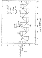
熱源を用いる代わりにバルブまたは機械的フローを用いて、再現性があるが時間に依存するフローを起こし、圧力降下(または上昇)Δp、時定数τ、または位相のずれδの観察ができるようにする。本明細書で開示する粘度計10は、再現性があるが時間に依存しないフローを起こして、アクチュエータ12による容積変位速度(rate of volumetric displacement)と実際の漏れフローとが数ミリ秒(ms)の間等しくなるときに、安定したΔpの観察ができるようにデザインされている。これを図2および3に概略して示す。3種類のガス、Ar、N2、およびC3H8に対するΔp信号に、曲線13、14、および15としてそれぞれ印をつけ、のこぎり歯曲線17で示したキャビティ16の容積変化ΔVc(パーセント)によって、アクチュエータまたは駆動装置12によって引き起こされた容積変化を示す。
【0016】
十分に強いアクチュエータの変位がガスの種類に依存せず、アクチュエータ12を「のこぎり歯」モードおよび一定の周波数fで駆動することができ、上式(1)が実際に成立すると仮定できるならば、全ての種類のガスは最終的にチャンバー内でその特有のΔpに達するが、同じ毛管11の流量において、Δpを測定し式(2)を用いることで各流体の粘度を測定することができる。上述した最初の2つの仮定を満足するように粘度計10がデザインされているならば、残る問題は、上述の等式が成立するのに十分な時間が半周期の間に存在するかどうかである。毛管半径rが小さすぎる場合には、Δp(t)ものこぎり歯のような関数である(ΔVcが小さい場合には断熱加熱効果は無視できる)。しかし毛管11が十分に大きい場合には、そのフローおよびΔpは、粘度計10内のガスの粘度に拘わらず、dV/dt=ΔVcf/2となるまで増加して、のこぎり歯17のピリオドの終わりまでその値に留まるだけである。その結果、粘度は下式(3)から得られる。
【0017】
η=πΔprc 4/(4ΔVcfLc) (3)
この関係を、数値モデルを用いた計算結果によって図3および4に示す。このモデルでは、所定のrc、Lc、およびfに対して、キャビティ容積を時間ステップΔz=0.1msに対応する小さな量ずつ増加させることによって、キャビティ圧力をPV=nRTに対応する量だけ変化させる。その結果、毛管を通るフローが開始してΔzの間の圧力変化の一部を取り除く。これはdV/dt=dVc/dt=ΔVcf/2と、Δpとの間の平衡状態に達するまで続く。これらの図から、次のことが分かる。(1)安定したΔp値が、のこぎり歯のピリオドの終わりの方で実現される。(2)このような安定したΔpのピリオドの値は、表示したガスC3H8、N2、およびArの粘度(20℃および1atmにおいて、それぞれ83、178、および224μPである)に比例する。(3)レイノルズ数Re=2rvρ/ηで表示したときに、毛管内における安定したΔpピリオドおよび層流(Re<2300)の両方が実現されるように、124および324Hzの周波数、およびη/ρが最も低いガス(図3および4ではプロパンであった)に対して、Rv=ΔVc/Vc、rc、およびLcの値を選択する必要があり、また選択することができる。324Hzの周波数を選択したのは、50Hzおよび60Hzの比較的高い高調波からほぼ同じように離れるようにするためである。(4)安定したΔpのピリオドに達する時定数は、流体の粘度が高くなりガス圧力が低くなるにつれて長くなる。時定数の結果を図5に示す。
【0018】
図3は、Δp、圧力振幅(cm水柱(WC))対zまたは時間(ms)のグラフである。このグラフは、振動容積17と、3種類のガスAr、N2、およびC3H8に対する漏出キャビティ16のΔpとを示しており、曲線13、14、および15によってそれぞれ表わされている。キャビティ16の振動容積17は、アクチュエータ12へ電気入力した結果である。曲線13、14、および15で示される圧力センサの変化は、センサ20によって検出される。これらのプロットは、22℃および0.7barの圧力で取った。周波数fは132Hzである。Rvは1パーセントである。最終的なΔpの63%に達する圧力平衡時間τは、3種類のガスに対して、それぞれ0.40、0.23、および0.153msである。停止しているときのキャビティ容積Vcoは、0.15cm3であり、毛管の長さLcおよび半径rcは、それぞれ0.3cmおよび0.17cmである。最大レイノルズ数Remaxは752である。
【0019】
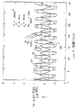
図4は、圧力振幅Δp(cmWC)対時間z(ms)のグラフである。このグラフは、振動容積17と、3種類のガスAr、N2、およびC3H8に対する漏出キャビティ16のΔpとを示しており、曲線13、14、および15によってそれぞれ表わされている。これらのプロットは、22℃および0.7barの圧力で取った。周波数fは323Hzであり、図2の場合の周波数fよりも約2.447倍速い。Rvは0.5%、Δzは0.05msであり、直線励起(linear excitation)τは0.18msである。VcoおよびLcは図3の場合と同様である。毛管の半径rcは、より大きくて0.2mmである。最大レイノルズ数は785である。対応する曲線13、14、および15の振幅は、図3の曲線の場合の約半分であることに注意されたい。しかし曲線13、14、および15の間の振幅の差は、図4の方が、図3よりも識別できるように見える。
【0020】
図5は、Δp、圧力振幅(cmWC)対Z、時間(ms)のグラフである。このグラフは、振動容積17と、3つの異なる絶対圧力paのN2に対する漏出キャビティ16のΔpとを示している。曲線14は0.7barのN2の場合であり、曲線18は1.0barのN2の場合であり、曲線19は1.5barのN2の場合である。このデータはデバイス10から、22℃および122Hzの周波数で取ったものであり、Rvは1%に等しい。Vcoは0.15cm3、Lcは0.3cm、rcは0.14mm、Remaxは846である。図5のこれらの曲線は、到達されるΔp−平衡状態が絶対圧力に依存しないことを示している。しかしこれらの曲線は、平衡状態に達する時定数τが圧力に依存することも示している。約0.29、0.23、および0.194msの時定数が、0.7、1.0、および1.5barの圧力に対してそれぞれ得られた。このことは、粘度を測定した後に絶対圧力を測定することにも役立ち得る。paτ2≒一定である。
【0021】
粘度計10を実現するためには、容積駆動装置(volumetric drivers)12、圧力センサ20、および可能性のあるシステム制約を考慮する必要がある。図6および7に、駆動装置12とセンサ20との間のバッフルまたは少なくとも部分的なバリアであり得るインターフェースまたはカップリング・デバイス28および29をそれぞれ特徴とするさらなる実施形態21および22を示す。バリア28または29は、駆動装置12からセンサまたは検出器20へのいかなる物理的エネルギー(すなわち機械的、電気、および/または熱)の輸送も防ぐためである。このエネルギーは、駆動装置12から検出器20へのΔp情報の伝達を妨げるか、遅らせるか、または抑制する可能性がある。バッフル28または29は、このような可能性のある歪みまたは破損(dilapidation)を、拡散、減衰、またはその他の適切に作用する機能を行なうことによって防ぐことができる。
【0022】
粘度計21は、アクチュエータ12とセンサ20との間のキャビティ16内に配置されたバッフル28を有する。バッフルまたはディヒューザー・プレート28は開口部または孔32を有するため、駆動装置12はセンサ20に、試験用ガスおよび開口部32を介して作用することができる。ガスは毛管11を通ってキャビティ16に入る。開口部32を示すために、ディヒューザー・プレート28の正面図を示す。ダイヤフラム33に面して配置されたプレート28が1つだけある。粘度計22は、アクチュエータ12とセンサ20との間のキャビティ16内に配置されたバッフル、バー、または減衰経路29を有する。通路または孔30によって試験用ガスの通路が与えられるため、駆動装置12はセンサ20に作用してガスの粘度を測定することができる。制御されたキャビティの漏れ口は、毛管開口部11を通る。
【0023】
アクチュエータは、いくつかの種類であり得る。一定速度の容積膨張または収縮を発生させるために、バルク(圧電性)PZT膨張、PZTバイモルフ・アクチュエータ(ツイータで使用されている)、および電磁スピーカを、駆動装置12として検討することができる。圧電トランスデューサの容積膨張は、変位は非常に小さいがガス密度の変化の影響を受けない大きな力を伴うため魅力的である。PZT膨張およびPZTバイモルフのアクチュエータの両方とも、温度補償する必要がある。これは電磁スピーカの場合には必要でない。
【0024】
測定される中央の偏位を、バイモルフ・アクチュエータ(PZT/真鍮の積層、Mallory Sonalert社(インディアナポリス、インディアナ州)製、25〜99の数量において1個あたり$0.55)で形成した。このアクチュエータは、15mmOD/0.11mm厚みの真鍮支持体+10mmOD/0.11mm厚みのPZT+9mmOD/0.02mm厚みのAg電極フィルムからなる。定格電圧≦25Vの下で、中央の偏位は約0.8μm/VRMSであった。また中央の偏位の測定を、電磁スピーカ(BRT1209P−01、Int’l.Components社(メルビル、ニューヨーク州)製、25〜99の数量の場合の価格は1個あたり$0.60)によっても行ない、1〜2VDCの最大入力および10mA最大に対して評価した。この50μm厚みスピーカ・ディスクの中央の偏位は、入力電圧に対してかなり直線的であることが分かった(図8の曲線31を参照)。変位は、−6〜+6VDCにおいて約7.5μm/Vであった。すなわち電圧(V)あたりのこの変位は、PZTバイモルフからの変位と比べて約10倍大きい。スピーカ・メンブレン33の支持については、多少注意深く考慮する必要がある(図2および6のデザイン10および21のメンブレン33にそれぞれ注意されたい)。
【0025】
スピーカ・メンブレン33からの漏れをなくすためにチャンバーまたはキャビティ16をシールする場合には、そのVc側と反対の側を周囲/外部の流体に対して開放して、周囲の圧力または温度が変化したときの変則的な影響を避ける必要がある。キャビティ16と反対側のメンブレン33における容積が、キャビティ16からの漏れに対して気密にシールされていない場合(BRT1206P−01の場合)には、毛管11に匹敵しかつ/またはオリフィスとしての漏れ機能に匹敵する。
【0026】
センサはいくつかの種類であり得る。粘度計10に必要な他の機能は、周囲とVcとの間のΔpセンサ20である。マイクロフォンが、要求を満足する最も低価格の選択であり得る。理想的なセンサ20は、硬いマイクロフォンである。すなわち変形によるVcへの影響がなく、出力は周波数に依存しない。エレクトレット・マイクロフォン(Panasonic of Secaucus(ニュージャージー)製、またはGentex of Carbondale(ペンシルベニア州)製、変形可能なメンブレンを有する)を、位相のずれの測定に用いた。これは、≦1.2cmのH2Oの約50〜60Hzの圧力変化に対して200mVの非増幅の出力をもたらした。ノイズ・レベルは2mVであった。これは、(1.2/1000)(2/200)・106=12ppmのキャビティ16内の圧力変化、または0.012cmのH2Oに相当する。
【0027】
電磁スピーカ(BRT1209P−01、Int’l.Components社製)を、駆動装置12として機能する類似のユニットと背中合わせにして、センサ20としてテストした。しかしそれらの磁界が干渉したので、良好な結果を得るにはシールディングが必要であろう。
【0028】
マイクロ・スイッチ24PC圧力センサ・チップ(Honeywell社(フリーポート、イリノイ州)製)をTO5ヘッダ(わずかな背圧も生じないように中央の孔の上)に搭載してシールしたところ、アクチュエータ12として機能するBRT1206P−01スピーカの1つとともに動作して、センサ20として良好に機能した。センサ20の出力は、毛管11に栓をしたときに駆動装置12の励起形状(サイン、矩形、のこぎり歯形状)に従うことが確かめられた。毛管の栓を抜いた後に、キャビティ16の容積変化速度と毛管11の流速との間の釣り合いが実現し、本発明が実証された。この動的に釣り合う間、確立されたΔpは流体の粘度を表わしていた。毛管11チューブのL/D比は、4よりも大きくなければならない。毛管11の入口は、乱流を最小限にするために、内部およびエッジで滑らかでなければならない。
【0029】
駆動装置12は同じであるが、圧電スピーカをセンサ20として機能させた実験では、理論的に予想されていた圧力に依存しない関係、η≒ΔGp0(ここでΔG=圧力センサの出力、p=絶対圧力)が、±5%の範囲の測定誤差内で得られた。この粘度センサは、市販の$0.60駆動装置12と$0.55センサ20とを単に背中合わせでエポキシ樹脂で接着したものから構成され、これらを60Hzで動作させた。要約して言えば、非常に低価格の在庫コンポーネントであることから、本発明の粘度計10、21、または22の製造を非常に費用対効果の高いものにできることが分かる。
【0030】
粘度計10には、いくつかの制限があり得る。第1に、可能性のある1つの制限は、フローの反転によるヘッド圧力である。フロー・駆動装置の周波数が増加するにつれて、それぞれの往復するフロー反転で生じる内部圧力が増加する。このような影響を避けるために、下式(4)に示すように、毛管11の圧力降下Δpcが内部圧力降下Δpiに等しくなる周波数を計算することができる。
【0031】
Δpc=(ΔVcf/2)・8ηLc/(πr4)および
Δpi=2ρv2/2=ρ(ΔVcf/(2ρr2))2 (4)
各方向の安定した容積フローΔV・f/2によって、平均速度v=ΔVcf/(2πr2)と反転時の内部圧力パルス2ρv2/2とが生じると仮定すれば、Δpc=Δpiに対して、下式が得られる。
【0032】
8ηLc=ρΔVcf/(2π)およびf=16πηLc/(ρΔVc)
(5)
η=0.000178g/(cm・s)またはυ=η/ρ=0.153cm2/s(20℃で1barのN2に対して)、Lc=1cmおよびVc=0.0001cm3の場合、f=77kHzが得られる。したがって殆どの用途において、この影響は低い周波数では概ね小さく各フロー反転でのみ生じるため、無視することができる。
【0033】
第2に、毛管11チューブ内における乱流の出現を避ける必要がある。上述の実施例の場合、r=0.008cmであれば、N2に対してRe=2rcv/ν=1909が得られる(しかしプロパンに対しては6935である)。しかしrc、ΔVc、およびfの変化の適切な組み合わせによって、実際に広い層流の範囲が得られる。乱流の開始を最小限にするためには、毛管11の先端のエッジを滑らかに作らなければならない。
【0034】
第3に、アクチュエータ、Δp、センサ、および制御された漏れ口(時間が経過しても詰まらない)の安定性は、長期間に渡る信頼性の高い稼動に対して明らかに重要である。安定した変位を回路により維持し、安定した漏れを多孔性プレート内の多数の漏れ口により維持する方法、およびセンサの適切な動作および精度の自己点検を、安定性の限界を克服するために推奨する。
【0035】
準静的粘度計10のコンポーネントおよびそれらのコストには、以下のものがある。のこぎり歯発生器が$0.4、スピーカ(10〜15mmの直径)が$0.22〜0.25(DAI社製)、マイクロフォン(6〜10mmの直径)が$0.22〜0.25、マイクロフォン増幅器およびデジタル出力用のアナログ・デジタル変換器(A/D)が約$2.00、1つまたは複数の0.2〜0.4mmの孔/長さ3〜6mmの毛管、または多孔性材料からなる複数の同等な制御された漏れ口が$0.10、さらに組み立て、較正、および種々雑多な材料が約$3.00である。このようにセンサの総費用は$6.00を下回り得るため、その用途およびビジネスの可能性は非常に広い。
【0036】
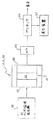
本発明の特徴には、キャビティ16へのまたはキャビティ16からの毛管11フロー(粘度に比例することが知られている)と、電気機械式流体変位装置/アクチュエータ12と、のこぎり歯電子駆動装置34とを組み合わせて、各AC駆動周期の2つのピリオドの少なくとも一方の間にキャビティ16内のΔpが安定することを可能にすることが含まれる。(少なくとも一方または)それぞれののこぎり歯ピリオドの終わりに確立されるΔpの測定値が、所望する粘度の表示である。絶対圧Paに大きく依存するのは、Δpである(しかしΔp/paではない)。Δpはセンサ20によって検知され、センサ20は出力をアナログ・デジタル変換器35へ送る(図9に示す)。デジタル出力は、プロセッサ36へ送られて処理される。プロセッサ36は、燃焼制御装置または調整装置などの何らかの装置へ送られ得るデジタルまたはアナログ出力を有する。また出力は、直接測定された粘度および相関する特性たとえば試験用ガスの酸素消費量またはその他のパラメータについての読み取り可能な情報を提供できる表示装置37へ送られる。その代わりにセンサ20の出力を、アナログ表示装置、プロセッサ、またはインターフェースへ直接送っても良い。
【0037】
一実施形態においては、圧電ツイータまたは静電スピーカではなく、低電圧のアクチュエータ12、電磁イヤホーン・スピーカを有していても良く、Δpセンサ20は、圧電性(好ましい)、圧電抵抗性、電磁的、エレクトレット、炭素接触、または容量の効果の何れかに基づくマイクロフォンである。本発明では、粘度を検知するだけでなく、測定された粘度と、初期時定数またはアクチュエータ12の入力とセンサ20の出力との間の位相のずれ(図3〜5に示す)とをさらに処理することによって、絶対圧力を検出しても良い。
【0038】
粘度計10、21、および22は、絶対圧力に全く依存しないため、圧力の減衰または位相のずれがある振動ワイヤーおよび水晶発信器に基づく関連技術の粘度計よりも有利である。また粘度計10、21、または22は、測定される流体の熱伝導度または比熱に全く依存しないため、熱励起に基づく粘度計よりも有利である。また加圧流体の定供給源によって駆動される毛管フローに基づくか、または物体落下のタイミングに基づく従来の粘度計よりも有利であり、すなわち定圧流体の高価な供給源、重力の一定の大きさおよび方向、または落下物体を供給し測定するための機器が全く必要でない。本粘度計は、その取り付け方位の影響を受けない。本デバイスを用いれば、前述したように粘度に加えて、初期時定数またはアクチュエータ入力とセンサ出力との間の位相ずれを用いることによって、絶対圧力を検知することもできる。これは関連技術の粘度計からは得られない特徴である。
【0039】
本明細書で開示されていない本発明の他の実施形態および変形が、特許請求の範囲に包含され、本発明の全ての均等物を含む特許請求の範囲によってのみ限定される。
【図面の簡単な説明】
【図1】燃料の酸素消費量と燃料の熱物理特性との間の関係を示す図である。
【図2】粘度計を示す図である。
【図3】3種類の異なるガスに対する漏出キャビティの振動容積とデルタ圧力とを示すグラフである。
【図4】3種類の異なるガスに対する漏出キャビティの振動容積とデルタ圧力とを示すグラフである。
【図5】3種類の異なるガスに対する漏出キャビティの振動容積とデルタ圧力とを示すグラフである。
【図6】粘度計のさらなる実施形態を示す図である。
【図7】粘度計のさらなる実施形態を示す図である。
【図8】粘度計のアクチュエータに対する駆動電圧対偏位を示すグラフである。
【図9】種々の用途で用いる粘度計および関連するコンポーネントを示す図である。[0001]
(background)
The present invention relates to viscosity detectors, and in particular to sensors based on delta pressure. More particularly, the invention relates to a viscosity sensor for measuring the oxygen consumption (oxygen demand) of a gas or liquid fuel intended for combustion (for complete combustion).
[0002]
Both existing and recently proposed quasi-static viscometers are dependent on fluid (ie, gas or liquid) density and pressure and are expensive (such as viscometers based on vibrating wires or quartz oscillators). Other viscometers have the disadvantage of being dependent on additional fluid properties (e.g., with thermally driven capillary flow) and tend to drift due to degraded and leaky valves (pressurized gas Capillary flow driven by periodic refilling from the source, valve closure, and for viscometers that rely on damped observations) or depending on its orientation (for a falling ball viscometer).
[0003]
The proposed sensor measures a known property of the fluid, the viscosity. Applying the sensor to a combustion control system allows for feed-forward operation and detection in less severe pre-combustion environments. The sensor can be simply proportional to the measured data (in one preferred measurement approach), and also has a simple relationship with the Wobbe number of fuel, oxygen consumption, or heating @ value. Therefore, the cost is low, and the contribution of the detection error to the overall combustion control error is relatively small.
[0004]
The present invention relates to utilizing or applying viscosity, a known property, to combustion control. The invention also relates to using the preferred approach to viscosity measurement for this application.
[0005]
The viscosity η is determined by the capillary (radius rcAnd length Lc) Are best known by a linear relationship to the laminar volumetric flow (dV / dt) and the pressure drop Δp. This is shown in equation (1).
[0006]
dV / dt = πΔprc 4/ (8Lcη) (1)
The first thing to note is that, to compensate for the fact that natural gas compositions vary, when looking for a means that can be burned at low cost with any composition, combustion control must be considered. A method for measuring the possibility of viscosity as an individual characteristic to the temperature and the calorific value without burning, wherein k (T1), K (T2), And the possibility of viscosity as a separate property for methods involving analytical measurements via correlations involving η, ie in relation to other properties.
[0007]
The viscosity of the fuel, also known as flue O2The concentration is also the fuel oxygen consumption DO2To show expected or actual changes. FIG. 1 shows η (curve 23) and other thermal physics (Qi) Properties: ρ, density (curve 26) and k, thermal conductivity (curve 24) and Cp, Specific heat (curve 25), and Cv, A comparison with the correction factor (curve 27) of a hot-wire anemometer, and these characteristics are separately calculated for the oxygen consumption of the fuel, DO2Figure shows how well it correlates. DO2When c increases, cpAlso looks promising, but η shows the most favorable monotonic decrease. Non-flammable CO2CpValue (8.83 cal / (mol · K), H2O is 8.60) is CH4And C2H6CpValues (8.50 and 12.42) but the non-combustible gas O2, N2, CO2(H2Η values are all CH4Exceeds the value of η.
[0008]
Two or more fuel properties are determined by the calorific value or DO2Although the accuracy that can be achieved is significantly increased by including in the correlation with (see the prior art cited below),pHas to be done digitally to measure the cost of the measurement, which also significantly increases costs. The above is based on the assumption that exhaust control and efficiency are the most important goals of all combustion controls. To achieve this goal the constant flue O2Or operate under excess air. Such operations maintain a constant air flow and reduce the fuel flow due to its composition variation (DO2And m*To be changed). Half of that concentration change is processed by the factor m. This is because m affects all orifice control or venturi control flow control situations. The purpose of adjusting the fuel flow to counter the fluctuations in Wb (Wobbe number) is similar, but not very accurate (when trying to keep A / F (air-fuel ratio) and exhaust constant). It returns to the definition of the Wobbe number like. Wb = ΔH / m*Where ΔH = O2The calorific value, not consumption, m*= (Mgas/ Mair)0.5It is. M is molar, and Wb is a non-hydrocarbon fuel component such as H2Bn (Bonne number = D02/ M*). DO2Alternatively, the correlation between Bn and viscosity is given by the following equation DO2= A + BηCOr Bn = A '+ B'η0.5Can be obtained respectively. A and B are correlation coefficients, and C is a correlation index. A 'and B' are similarly correlation coefficients. The correlation is similar to that of nature's law. Related information can be found in "Microsensors for Fluid Properties", U.S.A. Bonne and D.M. FIG. 6 on page 21 of Kubisiak, Scientific @ Honeyweller, Sensors @ Issue (1996). Further information is found in U.S. Patent No. 5,486,107 (U. Bonne, issued January 23, 1996), under the title "Determination of Fuel" Characteristics. This document is incorporated herein by reference.
[0009]
In order to explain the significance of the proposed viscometer-based combustion control system, in Table 1, some parameters related to the characteristics of the thermal conductivity sensor-based combustion control system were changed for the viscosity sensor-based system. Compare to case. As shown, in all respects, viscosity-based systems exhibit advantageous values, such as a lesser dependence of sensor output on pressure and temperature, but have a higher fuel-gas composition or fuel-fuel composition in the fuel + air mixture. The dependence on concentration is greater. The latter parameter was included to quantify the advantage of directly measuring the thermophysical properties of the fuel + air mixture. As shown, when the viscosity or thermal conductivity of a premixed fuel + air mixture is measured, the effects of pressure, temperature, and humidity are much greater than the effects of the desired fuel properties. A similar situation exists when measuring η or k in flue gas.
[0010]
In Table 1, DO2Or the advantage of viscosity over thermal conductivity as a λ, wavelength sensor. λ = (actual air-fuel ratio) ÷ (stoichiometric air-fuel ratio). According to this table, the viscosity is λ and D02It is shown to be about two times more sensitive to changes in thermal conductivity than thermal conductivity, but 30% less sensitive to pressure and temperature variations. This is DO2Or for the measurement of λ, it means that detecting the viscosity results in a sensor that is several times more accurate than in the case of heat conduction. Gas G20 is methane, and G271 is a gas mixture consisting of 74% methane and 26% nitrogen. p is pressure (bar) and T is temperature (° C.). W is the desired characteristic (λ or DO2) Is the dependent variable that measures The sensitivity of k and η is to variations in the nitrogen content of the fuel mixed with air, λ, T, p, and the nitrogen content of the pure fuel gas.
[0011]
[Table 1]
For the most favorable properties (k or η), the W values in columns 1-3 must be highest and 4-5 must be lowest. Obviously, viscosity is a preferred choice.
[0013]
(Summary of the Invention)
The viscometer disclosed herein does not rely on pressurized gas, the availability of microsensors, or a thermal driver, and its output is independent of absolute pressure (viscosity independent). To the extent that is). This viscometer is not affected by orientation and can be manufactured at low cost. The viscosity sensor is used to measure the oxygen consumption of various gas mixtures. The sensor comprises a fluid volume displacement device, an actuator or drive such as a speaker membrane, and a pressure sensor or detector such as a microphone, a controlled leak between the chamber or cavity, and the environment of the cavity and the viscosity sensor. (Leak). The drive, leak, and sensor electronics can be assembled from commercially available, inexpensive components. In summary, sensors have low manufacturing costs, good accuracy, reliability, intrinsic safety, and long service life.
[0014]
(Description of Embodiment)
In the
[0015]
dV / dt = πΔprc 4/ (8Lcη) (2)
Instead of using a heat source, a valve or mechanical flow is used to create a reproducible but time-dependent flow so that the pressure drop (or rise) Δp, time constant τ, or phase shift δ can be observed. I do. The
[0016]
If the displacement of a sufficiently strong actuator is independent of the gas type, the
[0017]
η = πΔprc 4/ (4ΔVcfLc) (3)
This relationship is shown in FIGS. 3 and 4 by calculation results using a numerical model. In this model, a given rc, Lc, And f, the cavity pressure is changed by an amount corresponding to PV = nRT by increasing the cavity volume by a small amount corresponding to the time step Δz = 0.1 ms. As a result, flow through the capillary starts to remove some of the pressure change during Δz. This is dV / dt = dVc/ Dt = ΔVcContinue until an equilibrium between f / 2 and Δp is reached. The following can be seen from these figures. (1) A stable Δp value is achieved towards the end of the sawtooth period. (2) The value of the period of such a stable Δp is the indicated gas C3H8, N2, And Ar at 20 ° C. and 1 atm, which are 83, 178, and 224 μP, respectively. (3) Frequencies of 124 and 324 Hz, and η / ρ such that both stable Δp periods and laminar flow (Re <2300) in the capillary are realized when represented by the Reynolds number Re = 2rvρ / η. For the lowest gas (propane in FIGS. 3 and 4)v= ΔVc/ Vc, Rc, And LcMust and can be selected. The 324 Hz frequency was chosen to be about the same away from the relatively high harmonics of 50 Hz and 60 Hz. (4) The time constant to reach a stable period of Δp increases as the viscosity of the fluid increases and the gas pressure decreases. The result of the time constant is shown in FIG.
[0018]
FIG. 3 is a graph of Δp, pressure amplitude (cm water column (WC)) versus z or time (ms). This graph shows the
[0019]
FIG. 4 is a graph of pressure amplitude Δp (cmWC) versus time z (ms). This graph shows the
[0020]
FIG. 5 is a graph of Δp, pressure amplitude (cmWC) versus Z, time (ms). This graph shows the
[0021]
To implement the
[0022]
The viscometer 21 has a baffle 28 disposed in the
[0023]
Actuators can be of several types. Bulk (piezoelectric) PZT expansion, PZT bimorph actuators (used in tweeters), and electromagnetic speakers can be considered as the
[0024]
The center excursions measured were formed with bimorph actuators (PZT / brass laminate, from Mallory @ Sonalert, Indianapolis, IN) at $ 0.55 / piece in 25-99 quantities. This actuator consists of a 15 mm OD / 0.11 mm thick brass support + 10 mm OD / 0.11 mm thick PZT + 9 mm OD / 0.02 mm thick Ag electrode film. Under rated voltage ≦ 25V, the center excursion was about 0.8 μm / VRMS. Also, the measurement of the center deviation can be measured by an electromagnetic speaker (BRT1209P-01, manufactured by Int'l. Components, Inc., Melville, NY, priced at $ 0.60 / piece for quantities of 25-99) And evaluated against a maximum input of 1-2 VDC and a maximum of 10 mA. The center excursion of this 50 μm thick speaker disk was found to be fairly linear with input voltage (see
[0025]
When sealing the chamber or
[0026]
The sensors can be of several types. Other functions required for the
[0027]
An electromagnetic speaker (BRT1209P-01, Int'l. Components, Inc.) was tested as a
[0028]
A microswitch 24PC pressure sensor chip (Honeywell, Freeport, Ill.) Was mounted and sealed on a TO5 header (above the central hole so as not to generate any back pressure). It worked with one of the functioning BRT 1206P-01 speakers and performed well as
[0029]
The driving
[0030]
[0031]
Δpc= (ΔVcf / 2) · 8ηLc/ (Πr4)and
Δpi= 2ρv2/ 2 = ρ (ΔVcf / (2ρr2))2(4)
The average velocity v = ΔV due to the stable volume flow ΔV · f / 2 in each directioncf / (2πr2) And the internal pressure pulse 2ρv at reversal2/ 2 occurs, then Δpc= ΔpiThe following equation is obtained for
[0032]
8ηLc= ΡΔVcf / (2π) and f = 16πηLc/ (ΡΔVc)
(5)
η = 0.000178 g / (cm · s) or υ = η / ρ = 0.153 cm2/ S (1 bar of N at 20 ° C)2), Lc= 1cm and Vc= 0.0001cm3In the case of f = 77 kHz is obtained. Thus, in most applications, this effect can be ignored since it is generally small at low frequencies and occurs only at each flow inversion.
[0033]
Second, it is necessary to avoid the appearance of turbulence in the capillary 11 tube. In the above embodiment, if r = 0.008 cm, N2Re = 2rcv / v = 1909 is obtained (but 6935 for propane). But rc, ΔVc, And f, a practically wide laminar flow range is obtained. In order to minimize the onset of turbulence, the leading edge of the capillary 11 must be made smooth.
[0034]
Third, the stability of actuators, Δp, sensors, and controlled leaks (not clogging over time) is clearly important for long-term reliable operation. How to maintain a stable displacement with a circuit and a stable leak with a large number of leaks in a porous plate, and self-checking the proper operation and accuracy of the sensor is recommended to overcome stability limitations I do.
[0035]
The components of the
[0036]
Features of the present invention include capillary 11 flow to and from cavity 16 (known to be proportional to viscosity), electromechanical fluid displacement device /
[0037]
In one embodiment, instead of a piezoelectric tweeter or electrostatic loudspeaker, it may have a
[0038]
The
[0039]
Other embodiments and variations of the invention not disclosed herein are encompassed by the claims, and are limited only by the claims, including all equivalents of the invention.
[Brief description of the drawings]
FIG. 1 is a diagram showing the relationship between fuel oxygen consumption and thermophysical properties of fuel.
FIG. 2 is a diagram showing a viscometer.
FIG. 3 is a graph showing the oscillating volume and delta pressure of a leak cavity for three different gases.
FIG. 4 is a graph showing oscillating volume and delta pressure of a leak cavity for three different gases.
FIG. 5 is a graph showing the oscillating volume and delta pressure of a leak cavity for three different gases.
FIG. 6 shows a further embodiment of the viscometer.
FIG. 7 shows a further embodiment of the viscometer.
FIG. 8 is a graph showing drive voltage versus deflection for a viscometer actuator.
FIG. 9 illustrates a viscometer and associated components used in various applications.
Claims (23)
前記駆動装置のダイアフラムから第1の距離で配置されたダイアフラムを有するセンサと、
前記駆動装置およびセンサのダイアフラムの周縁どうしの間および周縁の周りに、ダイアフラム間のキャビティを形成すべく形成されたフィッティングと、
キャビティに対する漏れ口を設けるために前記フィッティングに形成された開口部と、を備える準静的粘度計。A drive having a diaphragm;
A sensor having a diaphragm disposed at a first distance from the diaphragm of the drive;
Fittings formed to form cavities between the diaphragms between and around the periphery of the drive and sensor diaphragms;
An opening formed in said fitting to provide a leak to the cavity.
前記センサはマイクロフォンである、請求項3に記載の粘度計。The driving device is a speaker,
The viscometer according to claim 3, wherein the sensor is a microphone.
前記信号発生器は周波数fの信号を前記駆動装置へ出力するようになされており、
前記駆動装置は、圧力変化Δpでキャビティに出入りする容積ΔVcの流体をもたらすようになされており、
前記キャビティ内の流体の粘度ηは、(πΔprc 4)/(4ΔVcfLc)に等しくされている、請求項7に記載の粘度計。The opening is a capillary tube length L c and a radius r c,
The signal generator is configured to output a signal having a frequency f to the driving device;
Said drive is adapted to provide a volume of fluid ΔV c entering and exiting the cavity at a pressure change Δp;
The viscosity of the fluid η in the cavity, (πΔpr c 4) / is equal to (4ΔV c fL c), viscometer of claim 7.
ダイアフラムを有する駆動装置と、
前記駆動装置のダイアフラムに隣接するダイアフラムを有するセンサと、
前記駆動装置に並置された第1の開口端と前記センサに並置された第2の開口端とを有するフィッティングであって、前記駆動装置およびセンサとともにキャビティを形成するフィッティングと、
前記フィッティング内に形成された漏れ口と、を備える表示装置。A device that displays oxygen consumption based on viscosity for a fluid,
A drive having a diaphragm;
A sensor having a diaphragm adjacent to the diaphragm of the drive;
A fitting having a first open end juxtaposed to the drive device and a second open end juxtaposed to the sensor, the fitting forming a cavity with the drive device and the sensor;
A display device comprising: a leak hole formed in the fitting.
前記センサはマイクロフォンであり、
前記フィッティング内に形成された前記漏れ口は毛管チューブである、請求項12に記載の粘度に基づく酸素消費量表示装置。The driving device is a speaker,
The sensor is a microphone;
13. The viscosity-based oxygen consumption indicator of claim 12, wherein the leak formed in the fitting is a capillary tube.
前記構造物上に位置するアクチュエータと、
前記構造物上に位置し、前記アクチュエータに隣接する検出器と、
前記キャビティと流体を有する環境との間の漏れ口と、を備える準静的粘度計。A structure having a cavity;
An actuator located on the structure;
A detector located on the structure and adjacent to the actuator;
A quasi-static viscometer comprising a leak between the cavity and an environment having a fluid.
前記検出器は、前記アクチュエータのダイアフラムとほぼ同じ面に位置するダイアフラムを有している、請求項15に記載の準静的粘度計。The actuator has a diaphragm,
The quasi-static viscometer of claim 15, wherein the detector has a diaphragm located substantially in the same plane as the diaphragm of the actuator.
流体は前記アクチュエータと検出器との間の前記インターフェースを通過することができるようになされている、請求項17に記載の準静的粘度計。Fluid can enter the cavity through the leak;
The quasi-static viscometer of claim 17, wherein the fluid is adapted to pass through the interface between the actuator and a detector.
前記アクチュエータのダイアフラムは、圧力変化Δpでキャビティに出入りする容積ΔVcの流体をもたらすことができ、
前記検出器のダイアフラムは圧力変化Δpを検知し、
キャビティ内の流体の粘度ηは(πΔprc 4)/(4ΔVcfLc)である、請求項18に記載の準静的粘度計。The leakage opening is capillary tube length L c and a radius r c,
The actuator diaphragm may provide a volume ΔV c of fluid entering and exiting the cavity with a pressure change Δp;
The diaphragm of the detector detects a pressure change Δp,
The quasi-static viscometer according to claim 18, wherein the viscosity η of the fluid in the cavity is (πΔpr c 4 ) / (4ΔV c fL c ).
A、B、Cは相関係数である、請求項20に記載の準静的粘度計。The process for measuring the oxygen consumption D O2 of the fluid is based on D O2 = A + Bη C ,
21. The quasi-static viscometer of claim 20, wherein A, B, and C are correlation coefficients.
A’、B’は相関係数であり、
C’は約0.5である、請求項20に記載の準静的粘度計。The process for measuring the Bonne number B n of the fluid is based on B n = A ′ + B′η C ′ ,
A ′ and B ′ are correlation coefficients,
21. The quasi-static viscometer of claim 20, wherein C 'is about 0.5.
Applications Claiming Priority (1)
| Application Number | Priority Date | Filing Date | Title |
|---|---|---|---|
| PCT/US2000/015967 WO2001096832A1 (en) | 2000-06-09 | 2000-06-09 | Quasi-static viscometer |
Publications (2)
| Publication Number | Publication Date |
|---|---|
| JP2004503767A true JP2004503767A (en) | 2004-02-05 |
| JP2004503767A5 JP2004503767A5 (en) | 2007-04-19 |
Family
ID=21741474
Family Applications (1)
| Application Number | Title | Priority Date | Filing Date |
|---|---|---|---|
| JP2002510912A Pending JP2004503767A (en) | 2000-06-09 | 2000-06-09 | Quasi-static viscometer |
Country Status (7)
| Country | Link |
|---|---|
| EP (1) | EP1297317B1 (en) |
| JP (1) | JP2004503767A (en) |
| AT (1) | ATE426153T1 (en) |
| AU (1) | AU2000256039A1 (en) |
| CA (1) | CA2411956A1 (en) |
| DE (1) | DE60041834D1 (en) |
| WO (1) | WO2001096832A1 (en) |
Cited By (1)
| Publication number | Priority date | Publication date | Assignee | Title |
|---|---|---|---|---|
| JP2009058340A (en) * | 2007-08-31 | 2009-03-19 | National Institute Of Advanced Industrial & Technology | Viscometer |
Families Citing this family (2)
| Publication number | Priority date | Publication date | Assignee | Title |
|---|---|---|---|---|
| EP1707940A1 (en) * | 2005-03-31 | 2006-10-04 | Ecole Polytechnique Fédérale de Lausanne (EPFL) | Gas viscosity sensor |
| DE102015117468A1 (en) | 2015-10-14 | 2017-04-20 | Endress+Hauser Flowtec Ag | A method for determining properties of a hydrocarbon-containing gas mixture and apparatus therefor |
Family Cites Families (2)
| Publication number | Priority date | Publication date | Assignee | Title |
|---|---|---|---|---|
| SU1746256A1 (en) * | 1990-01-23 | 1992-07-07 | Тамбовское Высшее Военное Авиационное Инженерное Краснознаменное Училище Им.Ф.Э.Дзержинского | Method of measuring fluid viscosity basing on fluid oscillations |
| EP0554095A3 (en) * | 1992-01-30 | 1994-12-14 | Honeywell Inc | Determination of fuel characteristics |
-
2000
- 2000-06-09 AT AT00941320T patent/ATE426153T1/en not_active IP Right Cessation
- 2000-06-09 JP JP2002510912A patent/JP2004503767A/en active Pending
- 2000-06-09 DE DE60041834T patent/DE60041834D1/en not_active Expired - Fee Related
- 2000-06-09 AU AU2000256039A patent/AU2000256039A1/en not_active Abandoned
- 2000-06-09 WO PCT/US2000/015967 patent/WO2001096832A1/en active Application Filing
- 2000-06-09 CA CA002411956A patent/CA2411956A1/en not_active Abandoned
- 2000-06-09 EP EP00941320A patent/EP1297317B1/en not_active Expired - Lifetime
Cited By (1)
| Publication number | Priority date | Publication date | Assignee | Title |
|---|---|---|---|---|
| JP2009058340A (en) * | 2007-08-31 | 2009-03-19 | National Institute Of Advanced Industrial & Technology | Viscometer |
Also Published As
| Publication number | Publication date |
|---|---|
| ATE426153T1 (en) | 2009-04-15 |
| EP1297317A1 (en) | 2003-04-02 |
| DE60041834D1 (en) | 2009-04-30 |
| CA2411956A1 (en) | 2001-12-20 |
| AU2000256039A1 (en) | 2001-12-24 |
| WO2001096832A1 (en) | 2001-12-20 |
| EP1297317B1 (en) | 2009-03-18 |
Similar Documents
| Publication | Publication Date | Title |
|---|---|---|
| US6178811B1 (en) | Quasi-static viscometer | |
| US6308553B1 (en) | Self-normalizing flow sensor and method for the same | |
| JP5778619B2 (en) | Pressure sensor | |
| US20100107735A1 (en) | Gas Sensor | |
| JPH01206218A (en) | Flowmeter | |
| RU2206075C2 (en) | Means for measuring power consumption | |
| JP2004503767A (en) | Quasi-static viscometer | |
| JPH04504620A (en) | piezoelectric differential pressure vortex sensor | |
| KR920010269A (en) | Acoustic insulation liquid level sensor | |
| Greywall | Micromachined optical-interference microphone | |
| US7380459B1 (en) | Absolute pressure sensor | |
| JPS58160813A (en) | Vortex flow meter | |
| US20040177675A1 (en) | Gas gage utilizing internal resonance frequency | |
| JPH085435A (en) | Gas meter | |
| JP3209303B2 (en) | Vortex flow meter | |
| Sosna et al. | Response time of thermal flow sensors | |
| JP2000171282A (en) | Acoustic volume meter for measuring volume difference | |
| SU1364934A1 (en) | Method and device for determining gas pressure | |
| JPS60238742A (en) | Gas detecting device | |
| Hurst et al. | High temperature static and dynamic pressure transducer for combustion instability control using acoustic low-pass filter structures | |
| JP3038497B2 (en) | Piezoelectric differential pressure vortex sensor | |
| CN115329694A (en) | Fluid flow calculation method and differential pressure type flow sensor | |
| CN2835951Y (en) | Weak pulse signal detector | |
| Hurst et al. | Enhanced static-dynamic pressure transducer for the detection of acoustic level flow instabilities in gas turbine engines | |
| JPH09119858A (en) | Gas meter |
Legal Events
| Date | Code | Title | Description |
|---|---|---|---|
| A521 | Request for written amendment filed |
Free format text: JAPANESE INTERMEDIATE CODE: A523 Effective date: 20070129 |
|
| A621 | Written request for application examination |
Free format text: JAPANESE INTERMEDIATE CODE: A621 Effective date: 20070129 |
|
| A977 | Report on retrieval |
Free format text: JAPANESE INTERMEDIATE CODE: A971007 Effective date: 20080827 |
|
| A131 | Notification of reasons for refusal |
Free format text: JAPANESE INTERMEDIATE CODE: A131 Effective date: 20080829 |
|
| A601 | Written request for extension of time |
Free format text: JAPANESE INTERMEDIATE CODE: A601 Effective date: 20081201 |
|
| A602 | Written permission of extension of time |
Free format text: JAPANESE INTERMEDIATE CODE: A602 Effective date: 20081208 |
|
| A02 | Decision of refusal |
Free format text: JAPANESE INTERMEDIATE CODE: A02 Effective date: 20090303 |